


63
DIGITAL CENTRE-SURROUND PROCESSOR
OWNER'S MANUAL
TABLE OF CONTENTS
OVERVIEW |
3 |
|
SYSTEM FEATURES |
3 |
|
SYSTEM SPECIFICATIONS |
3 |
|
SP23 OPERATION |
4 |
|
EMERGENCY BYPASS |
4 |
|
SP23-10 (OCTAVE EQUALISERS) CARD POSITIONS |
4 |
|
SP23-30 (1/3 OCTAVE EQUALISERS) CARD POSITIONS |
4 |
|
SP23 INSTALLATION |
5 |
|
CONNECTING THE INPUTS TO THE SP23. |
6 |
|
CONNECTING THE SP23 OUTPUTS. |
7 |
|
AUTOMATION INTERFACE - 25-PIN D-CONNECTOR CONNECTION DATA |
9 |
|
SYSTEM ALIGNMENT |
10 |
|
1 |
– ALIGNMENT WITH PANASTEREO PROCESSORS |
11 |
2 |
– ALIGNMENT WITH DOLBY CP55 |
16 |
3 |
– ALIGNMENT WITH DOLBY CP65 |
21 |
4 |
– ALIGNMENT WITH DOLBY CP500 |
26 |
5 |
– ALIGNMENT WITH SMART MOD VI WITH DSP MATRIX |
30 |
6 |
– ALIGNMENT WITH SMART MOD VI WITH ANALOG MATRIX |
35 |
7 |
– ALIGNMENT WITH SMART MOD IIC |
39 |
8 |
– ALIGNMENT WITH ULTRA STEREO JSX1000 |
43 |
Surround EX is a trademark of Dolby Labs, Inc.
PANALOGIC CORPORATION PTY LIMITED
Ground floor, 44 Carrington Road
Castle Hill, NSW 2154
Australia
Phone: 61 2 9894 6655
Fax: 61 2 9894 6935
Email: panalogic@panalogic.com
Web: www.panalogic.com

PANASTEREO SP23 – Operation.
PANASTEREO SP23 DIGITAL SURROUND PROCESSOR
OVERVIEW
The Panastereo SP23 Surround Processor decodes 6.1 channel sound from existing digital
5.1 installations. The SP23 works with any brand of 5.1 digital sound processor is inserted between the left and right surround outputs of the sound processor and the surround amplifiers. The SP23 provides a decoded rear surround channel which can be fed to rear wall surround speakers via a rear surround amplifier.
SYSTEM FEATURES
∙High performance matrix decoding of centre (rear) surround information.
∙Choice of 10 band octave (SP23-10) or 30 band 1/3 octave (SP23-30) equalisers for all three surround channels.
∙Users with Panastereo processors can re-use the surround equaliser card from the cinema processor in the SP23 to save the cost of duplication.
∙Provides three channel mono surround for stereo analogue soundtracks.
∙Balanced inputs and outputs for hum and buzz free installation.
∙Superb noise and distortion performance.
∙EX decode and input level LED indicators.
∙CSP1200 / CP65 pin compatible 25way D automation connector.
∙Input / output connections via plug-in Phoenix connectors.
∙Power-off bypass and manual bypass facility.
∙Built-in power supply module.
∙1U standard rack mount chassis with front accessible plug in card modules.
∙Designed and manufactured in Australia.
∙Fully compatible with the Dolby Digital Surround EX(TM) format planned for Star Wars and other films to follow.
SYSTEM SPECIFICATIONS
Inputs: Ls and Rs inputs, 10k ohm balanced, Max input sensitivity: 220mV.
Outputs: Ls, Rs, Csl ,Csr. 100 ohm balanced, Max output level +20dBu.
Noise: Typically 78 dB (unweighted) 86dB (A weighted)
Distortion (any channel) 1kHz @ Dolby level: 0.03%
Dynamic Range: Typically 106dB
Dimensions: 430mm (W) x 247mm (D) x 44mm (H)
Weight:: 4.2kg
3
PANASTEREO SP23 – Operation.
SP23 OPERATION
The SP23 does not require any operator intervention for normal operation. The unit is automatically controlled by the cinema processor.
When a digital format is selected on the cinema processor the SP23 will switch to EX decode mode and the red DECODE-ON indicator will be illuminated. In Digital mode the left and right surround channel information is decoded into three channels, left, right and rear surround.
When any other format is selected on the cinema processor, the SP23 will switch to non-EX mode and the yellow DECODE-OFF indicator will be illuminated. In non-EX mode, if the surround channel information is mono (as with optical stereo film soundtracks), the surround signal is equally distributed to all three surround channels. If the surround signal is stereo, the left surround channel contains the left signal, the right surround channel contains the right signal and the rear channel contains both signals.
EMERGENCY BYPASS
In the event of a failure of the unit, it can be bypassed by pressing the red BYPASS button at the right front of the unit. This button is NOT a power switch but simply allows the left and right surround channels from the processor to be sent directly to the left and right surround power amplifiers. There is no rear surround in bypass mode.
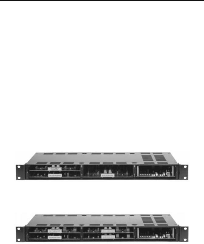
SP23-10 (Octave Equalisers) card positions
SP23-30 (1/3 Octave Equalisers) card positions
4

PANASTEREO SP23 – Installation.
SP23 INSTALLATION
RACK MOUNTING THE SP23
The SP23 can be mounted anywhere in the sound rack, although it is preferable from a wiring point of view to mount the unit between the sound processor and the amplifiers. Provision should be made for ventilation above the SP23, so avoid mounting the unit directly beneath other equipment that will prevent air circulation at the top of the SP23 chassis.
REAR SURROUND SPEAKER AND AMPLIFIER REQUIREMENTS
The rear wall surround speakers should be ideally of the same type as the side wall speakers to allow the best match in sound quality between the side and rear wall speakers. The rear wall amplifier and speaker system should have sufficient power handling capability to match that of either side wall system. The number of rear wall speakers will be determined by the width of the auditorium – the wider the room the more speakers will be needed. The spacing between each of the rear speakers should be no greater than the spacing between each of the side wall speakers.
INSTALLATION IN A TWO LEVEL CINEMA
The Panastereo SP23 can be easily adapted to dual level cinemas. Such cinemas, which are usually large older style cinemas, typically have an upstairs balcony and a downstairs stalls area beneath the balcony. For such cinemas, rear wall surround speakers will be required both upstairs and downstairs. In such cases the rear left output can be used to drive the upstairs speakers and the rear right output can be used to drive the downstairs speakers. In the SP23-10 there are separate equalisers for rear left and rear right channels so the upstairs and downstairs rear speaker systems can be separately equalised for optimum results.
CONTROL & AUTOMATION CONSIDERATIONS
The automation connector on the SP23 is pin compatible with Panastereo CSP1200, Panastereo CSP4200, Dolby CP65 and Dolby CP500 processors. When a standard pin for pin cable is used with any of the above processors, the rear surround decoding will be turned on for any digital or magnetic format and turned off for all other formats. For use with other processors, or if it is desired to alter which formats turn the decoding on or off, it will be necessary to make a custom cable. In this case, reference should be made to the automation pinout table in this manual.
5

PANASTEREO SP23 – Installation.
CONNECTING THE INPUTS TO THE SP23.
SOUND PROCESSOR WITH UNBALANCED OUTPUTS (DOLBY, SMART, ULTRA STEREO)
Disconnect the left surround and right surround connections at the sound processor outputs.
Use two-core shielded audio cable to connect the left and right surround outputs from the sound processor to the left and right inputs of the SP23.
Connect the “+” terminal from each sound processor output to the “+” terminal of each corresponding SP23 input.
Connect the ground terminal of each processor output to the “-“ terminal of each corresponding SP23 input.
Connect the cable shield to the “E” terminal of each SP23 input only. Do not connect the shields at the sound processor.
SOUND PROCESSOR WITH BALANCED OUTPUTS (PANASTEREO)
Disconnect the left surround and right surround connections at the sound processor outputs.
Use two-core shielded audio cable to connect the left and right surround outputs from the sound processor to the left and right inputs of the SP23.
Connect the “+” terminal from each sound processor output to the “+” terminal of each corresponding SP23 input.
Connect the “-“ terminal of each processor output to the “-“ terminal of each corresponding SP23 input.
Connect the cable shield to the “E” terminal of each SP23 input only. Do not connect the shields at the sound processor.
AUTOMATION CABLE
The SP23 must be connected to the cinema processor or digital processor automation connector.
The SP23 D25 automation connector is pin compatible with Panastereo CSP42000, CSP1200, Dolby CP65 and CP500 processors.
A pre-made 25 way ribbon cable is supplied with the SP23 for the above processors.
6
PANASTEREO SP23 – Installation.
CONNECTING THE SP23 OUTPUTS.
AMPLIFIERS WITH UNBALANCED INPUTS
Use two-core shielded audio cable to connect the left, right and rear surround outputs from the SP23 to the inputs of the amplifiers.
Connect the “+” terminal from each SP23 output to the “+” terminal of each corresponding amplifier input.
Connect the ground terminal of each SP23 output to the “-“ terminal of each corresponding amplifier input.
Connect the cable shield to the “E” terminal of each amplifier input only. Do not connect the shields at the sound processor.
AMPLIFIERS WITH BALANCED INPUTS
Use two-core shielded audio cable to connect the left, right and rear surround outputs from the SP23 to the inputs of the amplifiers.
Connect the “+” terminal from each SP23 output to the “+” terminal of each corresponding amplifier input.
Connect the “-“ terminal of each SP23 output to the “-“ terminal of each corresponding amplifier input.
Connect the cable shield to the “E” terminal of each SP23 input only. Do not connect the shields at the amplifier.
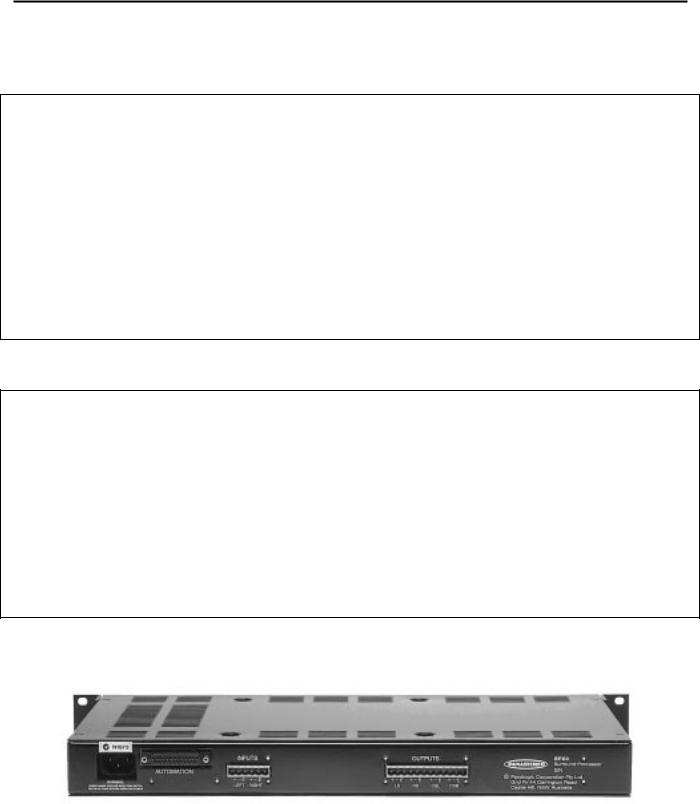
SP23 Rear Panel
7

PANASTEREO SP23 – Installation.
SETTING THE EQUALISER MODE JUMPERS
The SP23 has three EQUALISER MODE jumpers on the CM126 Power Supply/Control Card. The jumpers are marked LK1 – 3
The jumpers are factory set to match the equaliser configuration as shipped from the factory.
LK1 – Selects the input for the third equaliser slot (the upper middle slot).
∙If the SP23 is fitted with 1/3 octave equalisers for the left and right surround channels (left eq in upper left slot, and right eq in upper middle slot) then this jumper should be in the left “RS” position. This ensures that the right surround signal from the matrix is fed to the right surround equaliser
∙If the SP23 is fitted with a stereo octave equaliser for the left and right surround channels (upper left slot), AND a 1/3 octave equaliser is fitted to the upper middle slot AND you wish to use the future L-R output from the SP23 this jumper must be in the right “L-R” position .
LK2 – Selects octave or third octave equaliser mode for the left and right equalisers.
∙If the SP23 is fitted with a stereo octave equaliser for the left and right surround channels (upper left slot), this jumper should be in the left “OCT” position .
∙If the SP23 is fitted with 1/3 octave equalisers for the left and right surround channels (left eq in upper left slot, and right eq in upper middle slot) then this jumper should be in the right “1/3” position.
LK3 – Selects stereo or mono equaliser mode for the rear surround equaliser.
∙If the SP23 is fitted with a 1/3 octave equaliser for the rear surround channel (bottom middle slot) this jumper should be in the left “CS” position . (This will feed the output from the equaliser to both left and right rear outputs).
∙If the SP23 is fitted with a stereo octave equaliser for the rear surround channel (bottom middle slot) and you wish to use just the left equaliser for both the left rear and right rear channels, this jumper should be in the left “CS” position . (This will feed the left equaliser output to both the left and right rear outputs).
∙If the SP23 is fitted with a stereo octave equaliser for the rear surround channel (bottom middle slot) and you wish to use separate equalisers for the left rear and right rear channels, this jumper should be in the right “L-R” position .
∙If the future fourth surround channel is used, the right rear output will carry this signal if this jumper is in the right “L-R” position .
8

PANASTEREO SP23 – Installation.
AUTOMATION INTERFACE - 25-PIN D-CONNECTOR CONNECTION DATA
3LQ 1R |
63 )XQFWLRQV |
'(&2'( |
&63 )XQFWLRQV |
|
|
|
|
|
)LOP 0RQR 6HOHFW |
2)) |
)LOP 0RQR 6HOHFW |
|
)LOP 6WHUHR 6HOHFW |
2)) |
)LOP 6WHUHR 6HOHFW |
|
)LOP 6WHUHR 6U 6HOHFW |
2)) |
)LOP 6WHUHR 6U 6HOHFW |
|
1 6 6HOHFW |
2)) |
1 6 6HOHFW |
|
)LOP 'LJLWDO 6HOHFW |
21 |
)LOP 'LJLWDO 6HOHFW |
|
)LOP 'LJLWDO 6HOHFW |
21 |
)LOP 'LJLWDO 6HOHFW |
|
1 6 6HOHFW |
2)) |
1 6 6HOHFW |
|
)LOP 0DJ $X[ 6HOHFW |
21 |
)LOP 0DJ $X[ 6HOHFW |
|
|
|
5HPRWH )DGHU 6HOHFW |
|
|
|
0XWH 6HOHFW |
|
|
|
5HPRWH )DGHU 5HI 9ROWDJH |
|
&RPPRQ 'LJLWDO *URXQG |
|
&RPPRQ 'LJLWDO *URXQG |
|
|
|
5HPRWH )DGHU :LSHU |
|
|
|
)LOP 0RQR ,QGLFDWRU |
|
|
|
)LOP 6WHUHR ,QGLFDWRU |
|
|
|
)LOP 6WHUHR 6U ,QGLFDWRU |
|
|
|
1 6 ,QGLFDWRU |
|
|
|
)LOP 'LJLWDO ,QGLFDWRU |
|
|
|
)LOP 'LJLWDO ,QGLFDWRU |
|
|
|
1 6 ,QGLFDWRU |
|
|
|
)LOP 0DJ $X[ ,QGLFDWRU |
|
|
|
5HPRWH )DGH ,QGLFDWRU |
|
|
|
0XWH ,QGLFDWRU |
|
|
|
$ 9 ,QSXW 6HOHFW |
|
|
|
3URM 6HOHFW + 3 / 3 |
SP23 automation connector pins 1-8 should be pulled low (connected to pin 12) to select a format. Pins 1, 2, 3, 4 & 7 select “decode off”.
Pins 5, 6 & 8 select “decode on”.
9

PANASTEREO SP23 – Alignment.
SYSTEM ALIGNMENT
Refer to the appropriate section of the manual for alignment with various sound processors.
1 – Panastereo CSP3200, CSP4200, CSP1200
2 - Dolby CP55
3 – Dolby CP65
4 - Dolby CP500
5 - Smart MOD 6 with DSP Matrix
6 - Smart MOD 6 with Analog Matrix
7 - Smart MOD IIC
8 – Ultra Stereo JSX 1000
10
PANASTEREO SP23 – Alignment with PANASTEREO PROCESSORS
1 – ALIGNMENT with PANASTEREO PROCESSORS
Equipment required: CM218 Pink Noise Card, Real Time Analyser (RTA)
1.SET UP REAL TIME ANALYSER
2.PRE-SET SP23 OUTPUT LEVELS
3.SWITCH SP23 TO BYPASS
4.BYPASS SURROUND EQUALISERS
Set up a Real Time Analyser and position the microphones in the auditorium.
Turn all four output trimmers on the SP23 anticlockwise until you feel a slight click.
Switch the SP23 to bypass mode (Red Bypass button IN).
At the rear of the Panastereo processor, switch the Surround Equaliser Bypass switch to the BYPASS position. If necessary remove the surround equaliser card from the processor and place it in the top left slot of the SP23.
5.INSTALL PINK NOISE CARD
Remove the CM224 Matrix Decoder card from the CSP sound processor and install the pink noise generator in it’s place.
6.SELECT “OPTICAL STEREO” FORMAT Select “Optical Stereo” on sound processor to
output pink noise to the auditorium.
7.SET PROCESSOR VOLUME TO “7.0”
8.CHECK SPL LEVELS ON ALL CHANNELS
Set the sound processor volume control to level “7.0” and keep it there for all subsequent adjustments.
Check that the SPL levels for all of the channels are correct (85dBC per channel). If not, adjust the output level trimmers on the CM329 or CM349 Audio Output card for a level of 85dBC from each channel.
9. SELECT “DIGITAL” FORMAT |
|
Select the sound processor to DIGITAL |
|
|
format. Check that the red “DECODE-ON” |
|
|
LED is illuminated on the SP23 |
|
|
|
11

PANASTEREO SP23 – Alignment with PANASTEREO PROCESSORS
10.REMOVE AUTOMATION CONNECTION
11.SELECT “OPTICAL STEREO” FORMAT
12.TURN OFF SP23 BYPASS
13.SET PINK NOISE CARD TO LS
14.ADJUST SP23 LS INPUT LEVEL
15.COARSE SET LS SPL LEVEL TO 85dBC
16.EQUALISE LEFT SURROUND CHANNEL
17.SET LS SPL LEVEL TO 85dBC
18.SELECT RIGHT SURROUND ON THE PINK NOISE CARD
19.ADJUST SP23 RIGHT SURROUND INPUT LEVEL
20.COARSE SET RIGHT SURROUND SPL LEVEL TO 85dBC
Disconnect the D25 automation cable from the SP23. (This is to prevent the sound processor from switching the SP23 back to Optical mode)
Select the sound processor to OPTICAL STEREO (to send pink noise to the outputs).
Switch the SP23 out of bypass mode (Red Bypass button OUT).
Switch on the Left Surround button on the Pink Noise card.
Adjust the Left Input trimmer on the SP23 so that the two green LEDs for the left channel are equally illuminated.
Adjust the Left Surround Output trimmer on the SP23 for approximately 85dBC in the auditorium.
Remove the Left/Right Equaliser card from the SP23 and connect it via the extender card and cable. Adjust the left equaliser controls for a frequency response in accordance with the standard ISO surround channel response curve.
Re-adjust the Left Surround Output trimmer on the SP23 for 85dBC in the auditorium.
Switch off the Left Surround button and press the Right Surround button on the Pink Noise Card.
Adjust the Right Input trimmer on the SP23 so that the two green LEDs for the right channel are equally illuminated.
Adjust the Right Surround Output trimmer on the SP23 for approximately 85dBC in the auditorium.
12
PANASTEREO SP23 – Alignment with PANASTEREO PROCESSORS
21.EQUALISE RIGHT SURROUND CHANNEL
22.SET RIGHT SURROUND SPL LEVEL TO 85dBC
23.SELECT BOTH LS AND RS ON PINK NOISE CARD
24.IF A TWO CHANNEL REAR SURROUND AMPLIFIER IS INSTALLED GOTO 31
25.COARSE SET LEFT REAR SURROUND SPL LEVEL to 85dBC
26.EQUALISE REAR SURROUND CHANNEL
27.SET REAR SURROUND SPL LEVEL TO 91dBC
28.RE-CONNECT AUTOMATION CABLE
29.REMOVE PINK NOISE CARD
Adjust the right equaliser controls for a frequency response in accordance with the standard ISO surround channel response curve.
Re-adjust the Right Surround Output trimmer on the SP23 for 85dBC in the auditorium.
Switch on both left and right surround on the Pink Noise Card
Adjust the Rear Left Surround Output trimmer (CSL) for approximately 85dBC SPL in the auditorium.
Remove the Rear Equaliser from the SP23 and connect it via the extender card and cable. Adjust the left equaliser controls for a frequency response in accordance with the standard ISO surround channel response curve.
Replace the Rear Equaliser card and adjust the Rear Left Surround Output trimmer (CSL) on the SP23 for 91dBC in the auditorium.
Re-connect the automation cable to the SP23.
Remove the pink noise card from the processor and replace with the CM224 matrix card.
|
30. END OF PROCEDURE |
|
The system is now ready to use. |
|
|
|
|
|
|
|
|
|
|
|
|
31.ALIGNMENT OF TWO CHANNEL REAR SURROUND AMPLIFIER
13

PANASTEREO SP23 – Alignment with PANASTEREO PROCESSORS
32.TURN OFF REAR RIGHT AMPLIFIER
33.COARSE SET REAR LEFT SURROUND SPL LEVEL to 85dBC
34.EQUALISE REAR LEFT SURROUND CHANNEL
35.SET REAR LEFT SURROUND SPL LEVEL TO 88dBC
36.TURN OFF LEFT REAR AMPLIFIER AND TURN ON RIGHT REAR AMPLIFIER
37.COARSE SET RIGHT REAR SURROUND SPL LEVEL to 85dBC
38.EQUALISE REAR RIGHT SURROUND CHANNEL
39.SET REAR RIGHT SURROUND SPL LEVEL TO 88dBC
40.TURN ON REAR LEFT AMPLIFIER
41.RE-CONNECT AUTOMATION CABLE
42.REMOVE PINK NOISE CARD
Switch off or disconnect the rear rightsurround amplifier.
Adjust the Rear Left Surround Output trimmer (CSL) for approximately 85dBC SPL in the auditorium.
Remove the Rear Equaliser from the SP23 and connect it via the extender card and cable. Adjust the left equaliser controls for a frequency response in accordance with the standard ISO surround channel response curve.
Adjust the Rear Left Surround Output trimmer (CSL) on the SP23 for 88dBC in the auditorium.
Switch off or disconnect the rear left-surround amplifier and switch on or connect the rear right surround amplifier.
Adjust the Rear Right Surround Output trimmer (CSR) for approximately 85dBC SPL in the auditorium.
Adjust the right equaliser controls for a frequency response in accordance with the standard ISO surround channel response curve.
Replace the Rear Equaliser card and adjust the Rear Right Surround Output trimmer (CSR) on the SP23 for 88dBC in the auditorium.
Switch on or re-connect the rear left surround amplifier.
Re-connect the automation cable to the SP23.
Remove the pink noise card from the processor and replace with the CM224 matrix card.
14
 Loading...