

Panastereo CX230EX User Manual
PPAANNAASSTTEERREEOO
CX230EX
CINEMA BOOTH MONIT0R
OWNER'S MANUAL

PANASTEREO CX230 CINEMA MONITOR
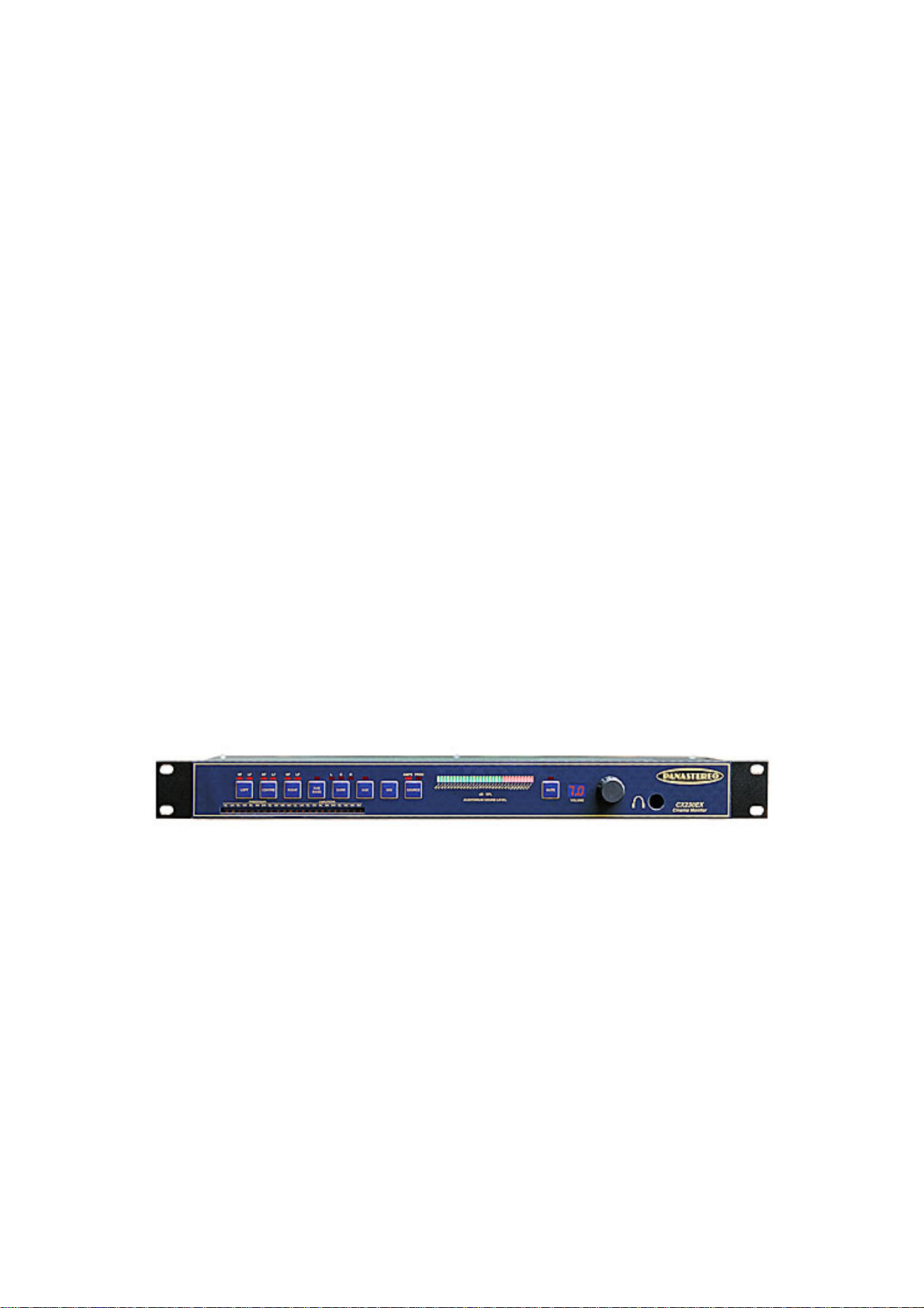
PANASTEREO CX230EX CINEMA BOOTH MONITOR
OVERVIEW
The CX230 Monitor is the world’s first computer cont r olled booth monitor. It is simple to use,
provides advanced features not previously found in booth monitor equipment and has been
designed for easy interface t o com put er automation systems via a standard RS232 interface
connector.
SYSTEM FEATURES
•
Single-chip microprocessor control system with power supervision and watchdog circuits provides high
immunity to interference for reliable latch-up-free operation.
•
Monitoring of both sound processor outputs and amplifier outputs.
•
Full monitoring of biamp systems.
•
Built-in analogue to digital converter with digital bargraph meter for auditorium volume indication.
•
Fast Mute function.
•
Two-digit LED digital volume indicator.
•
Built-in compressor for easier monitoring of highly dynamic (SR or digital) soundtracks.
•
Built-in stereo 25watt monitor amplifier.
•
All inputs are balanced and isolated for low noise, high quality monitoring and zero interaction with the
cinema sound system.
•
All functions (including volume control) accessible via RS232 serial interface.
•
Digitised auditorium sound level available via RS232 serial interface for remote indication of volume level
with computer automation systems.
•
All monitor connections via removable mini-Phoenix connectors so the monitor chassis can be easily
removed for service.
SYSTEM SPECIFICATIONS
Sound processor Inputs: Nominal 300mV input sensitivity, 10k ohm balanced
Amplifier Inputs: Nominal 3V input sensitivity, 100k ohm balanced
Amplifier Output Power: 2 x 25W RMS into 8 ohms.

PANASTEREO CX230 CINEMA MONITOR
CX230 OPERATION
MONITORING AN INDIVIDUAL CHANNEL
Select a channel to be monitored by pressing the pushbutt on for the appropriate channel once.
An LED indicator will illuminate above the selected input button. Adj ust the volume control for a
comfortable listening level. The volume is indicated by the 2-digit display to the lef t of the control.
Biamp installations only:
It is possible to monitor each of the f r ont channel high and low frequency outputs separately.
Press the left, centre or right pushbutton once to monitor a mix of the high and low frequency
outputs for each channel.
Press the same button a second time to monit or the high frequency output only. Press the same
button a third time to monitor just the low frequency output.
Repeatedly pressing the same button will cycle thr ough t he above three options.
MONITORING A MIX
When the MIX but t on is pr essed, the monitor output will be a blend of the front three channels
(left, centre and rig ht ) . In MIX mode a compressor is automatically inserted t o r educe t he
difference in volume between very loud and very soft signals. This m akes it easier to monitor
digital and SR soundtracks. The com pressor can be disabled by setting the options. (See
Installation section).
The surround channel is not included in the mix because the delay which is normally introduced in
the cinema processor for the sur r ound channel m ay cause confusing echo effects. The surround
and sub bass channels must be monitored individually.
MONITORING THE PROCESSOR OUTPUTS OR THE AMPLIFIER OUTPUTS
Press the SOURCE pushbutton to select either t he out puts from the sound processor or t he
outputs from the amplifiers.
Repeatedly pressing the SOURCE button will toggle back and forth between the processor and
the amplifier outputs.
MUTING THE MON ITOR OU TPUTS
Press the MUTE button to silence the monitor without changing the volume setting. Press the
MUTE button a second time to restore the monitor output to normal.
(The monitor can also be muted by turning the volume down to zero, but in this case the volume
must be turned up again to restor e t he previous listening level).

PANASTEREO CX230 CINEMA MONITOR
CX230 INSTALLATION
CONNECTING THE SOUND PROCESSOR OUTPUTS.
NOTE: For non-biamped installations, the left channel should be connected to the LL input , the
centre channel to the CL input and right channel t o t he RL input.
1.
SOUND PROCESSOR WITH UNBALANCED OUTPUTS (DOLBY, SMART, ULTRA STEREO)
Use two-core shielded audio cable to connect the outputs fr om the sound processor to the monitor
“from processor” inputs.
Connect the “+” terminal f r om each sound processor output to the “+” t er minal of each
corresponding monitor “From Processor” input.
Connect the ground terminal of each processor output to the “-“ terminal of each corresponding
monitor “From Processor” input .
Connect the cable shield to the “E” terminal of each monitor “from pr ocessor” input only. Do not
connect the shields at the sound processor.
2.
SOUND PROCESSOR WITH BALANCED OUTPUTS (PANASTEREO)
Use two-core shielded audio cable to connect the outputs fr om the sound processor to the monitor
“From Processor” inputs.
Connect the “+” terminal f r om each sound processor output to the “+” t er minal of each
corresponding monitor “From Processor” input.
Connect the “-“ terminal of each processor output to the “-“ terminal of each corresponding
monitor “from processor” input.
Connect the cable shield to the “E” terminal of each monitor “from pr ocessor” input only. Do not
connect the shields at the sound processor.
CONNECTING THE AMPLIFIER OUTPUTS.
NOTE: For non-biamped installations, the left channel should be connected to the LL input , the
centre channel to the CL input and right channel t o t he RL input.
Use light gauge unshielded cable for t his purpose.
Connect the “+” (Red) terminal of each amplifier output to t he “ + ” terminal of each corresponding
monitor “From Amplifier” input.
Connect the “-“ (Black) terminal of each amplifier to the “-“ terminal of each corresponding monitor
“From Amplifier” input .
NOTE:
MONITOR OR CONNECT THE “-“ (BLACK) TERMINALS OF THE AMPLIFIERS TOGETHER. SUCH
CONNECTIONS MAY CAUSE CROSSTALK, UNPREDICTABLE AMPLIFIER BEHAVIOUR OR DAMAGE
TO WIRING.
DO NOT USE A SINGLE GROUND CONNECTION BETWEEN THE AMPLIFIERS AND THE

PANASTEREO CX230 CINEMA MONITOR
CX230 INSTALLATION con’t
CONNECTING THE MONITOR SPEAKER OUTPUTS
Use medium gauge (minimum 0. 75m m 2) twin polarised wire (figure 8) between each of the
monitor speaker outputs and the m onitor speakers. The monitor speakers can be 8 or 4 ohms.
If you are using only one speaker, connect it t o the left channel output and set the
“MONO/STEREO” switch at the back of the monitor unit to the “MONO” position. O therwise
ensure that the “MONO/STEREO” switch is in the “ ST EREO ” position.
CONNECTING THE SERIAL INTERFACE TO A COMPUTER AUTOMATION SYSTEM.
Use 4-core shielded computer or audio cable. The CX 230 is configured as a DCE device (Data
Circuit Terminating Eq uipm ent ), i.e. pin 2 = transmit data out and pin 3 = r eceive data in. Connect
one conductor to pin 2 , one to pin 3 and one conductor to pin 5 (ground). The fourt h conductor
can be left unused or also connected to pin 5 (g r ound) . Solder the cable shield to the body of the
D-connector plug.
If the connection is to a DTE device (Data T erminal Equipment) such as a PC or the Panalogic
RC140 automation unit, the cable should be wired pin-for- pin (i.e. pin 2 to pin 2, pin 3 to pin 3, and
pin 5 to pin 5). If the connection is t o anot her DCE device, pins 2 and 3 m ust be crossed over
(reversed) at one end.
SETTING THE OPTIONS WITH THE VIRTUAL DIP SWITCHES
The CX230 has a number of options which may be accessed using the following method:
Press and hold the “MIX” button for at least 2 seconds. The bargraph display will change to show
a red bar at the extreme right. At the extreme left of t he bargraph display the first 4 gr een LEDs
indicate which options are set. To change an option, pr ess t he cor responding button to togg le the
LED on or off. For example t he far left butt on “ LEFT” will toggle the firs t green LED (option 1).
The next button “CENTRE” will toggle the second green LED (option 2) etc.
The available options are as follows:
Option 1 (LED 1) – Select 1.5 dB per division resolution for the bargraph meter. (Norm al
resolution is 3dB per division).
Option 2 (LED 2) – Defeat compressor . The MIX compressor is bypassed at all times.
Option 3 (LED 3) – Defeat biam p m ode. Pressing the LEFT, CENTRE or RIGHT buttons always
selects only the LF input.
Option 4 (LED 4) – Disable selection of processor inputs. The “SOURCE” button is lock ed in
“AMPS” mode. “PROC” cannot be selected.
To exit the DIP switch mode press and hold the “MIX” butt on for at least 2 seconds. The red bar
at the right of the bar graph will disappear to indicate normal m et er mode.
 Loading...