

Panasonic of North America 9TAWX CT2020 User Manual
Before attempting to connect or operate this product,
please read these instructions carefully and save this manual for future use.
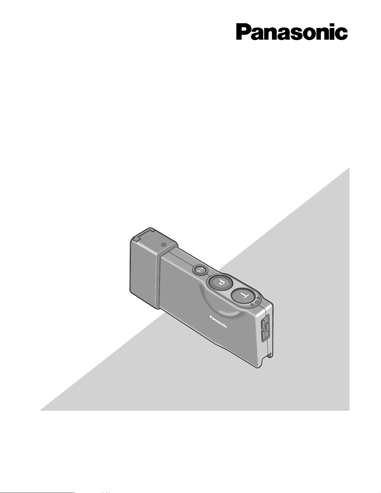
Order Taker Unit
Operating Instructions
Model No. WX-CT2020
SAMPLE
A
B
WX-CT2020

2
The serial number of this product may be found in the battery compartment of the unit.
You should note the serial number of this unit in the space
provided and retain this book as a permanent record of your
purchase to aid identification in the event of theft.
Model No. WX-CT2020
Serial No.
CAUTION
It is a violation of Federal Law to begin operating this system prior to obtaining an FCC Radio License. The FCC ID
number for this radio equipment is listed below.
FCC ID: ACJ9TAWX-CT2020
Danger of explosion if battery is incorrectly replaced.
Replace only with the same or equivalent type.
ATTENTION:
A battery that is recyclable powers the product
you have purchased. Please call 1-800-8-BATTERY for information on how to recycle this battery.
Ni-MH
FEDERAL COMMUNICATIONS COMMISSION INTERFERENCE STATEMENT
This equipment has been tested and found to comply with the limits for a Class A digital device, pursuant to part 15 of the
FCC Rules. These limits are designed to provide reasonable protection against harmful interference when the equipment is
operated in a commercial environment. This equipment generates, uses, and can radiate radio frequency energy and, if
not installed and used in accordance with the instruction manual, may cause harmful interference to radio communications.
Operation of this equipment in a residential area is likely to cause harmful interference in which case the user will be
required to correct the interference at his own expense.
FCC Warning: To assure continued FCC emission limit compliance, use only the provided power supply cord and shielded
interface cable when connecting this device to the computer. Also, any unauthorized changes or modifications to this
equipment would void the user's authority to operate this device.
This device complies with Part 15 of the FCC Rules. Operation is subject to the following two conditions: (1) This device
may not cause harmful interference, and (2) this device must accept any interference received, including interference that
may cause undesired operation.
Responsible Party: Matsushita Electric Corporation of America
1707 N. Randall Rd., Elgin IL. 60123
Contact Source: Panasonic Digital Communications & Security Company
866-472-6767

3
INTRODUCTION
Panasonic WX-CT2020 Order Taker Unit is designed for the use in Panasonic Wireless Communication System. Using with
WX-C1027A Headset (option), you can communicate by voice with other store personnel and the customer.
FEATURES
• Compatible center modules: WX-C1010, WX-C1011, and WX-CC2010 (Refer to "SW#8" on p. 7 "DIP Switch Setup".)
• Noise and interference reduction by use of UHF band
• Facilitated frequency setting by use of phase lock loop (PLL)
• A/B channel selection available for double drive-through (DDT) (Refer to "SW#2" on p. 7 "DIP Switch Setup".)
• Talk mode selectable between Talk Lock and Talk PTT (Refer to p. 9 "Optional Mode Setup".)
• Page mode selectable between Page Lock and Page PTT (Refer to p. 9 "Optional Mode Setup".)
PRECAUTIONS
• All setup procedures of this product should be performed by qualified service personnel or system installers.
• Use only Panasonic authorized batteries like the rechargeable Ni-MH 3.6 V.
• Follow the battery care and handling instructions.
• Read the instructions included with the battery charger.
• Charge the battery when the power indicator lights up in red and a beep is heard in the headset. Fully charge the battery.
Failure to do so may shorten the operating time.
CONTENTS
CONTENTS ............................................................................................................................................... 3
INTRODUCTION ....................................................................................................................................... 3
FEATURES ................................................................................................................................................ 3
PRECAUTIONS ......................................................................................................................................... 3
NAMES & FUNCTIONS .............................................................................................................................. 4
BATTERY LOADING & REPLACEMENT ................................................................................................... 6
● Loading .............................................................................................................................................. 6
● Replacement ...................................................................................................................................... 6
SETUP PROCEDURES .............................................................................................................................. 6
● Opening the Switch Pocket ................................................................................................................ 6
● Channel Group Selection ................................................................................................................... 7
● DIP Switch Setup ................................................................................................................................ 7
● Channel Interference Check .............................................................................................................. 7
● Operation Mode Setup ....................................................................................................................... 9
OPERATING PROCEDURES ..................................................................................................................... 11
● Turning the Power On/Off ................................................................................................................... 11
● Communications with Customers (TALK) ...........................................................................................11
● Communications with Other Store Personnel (PAGE) ........................................................................ 12
WHEN DISCONNECTING THE HEADSET PLUG ...................................................................................... 12
TROUBLESHOOTING ................................................................................................................................ 13
SPECIFICATIONS ...................................................................................................................................... 14
STANDARD ACCESSORIES ..................................................................................................................... 14
OPTIONAL ACCESSORIES ....................................................................................................................... 14
4
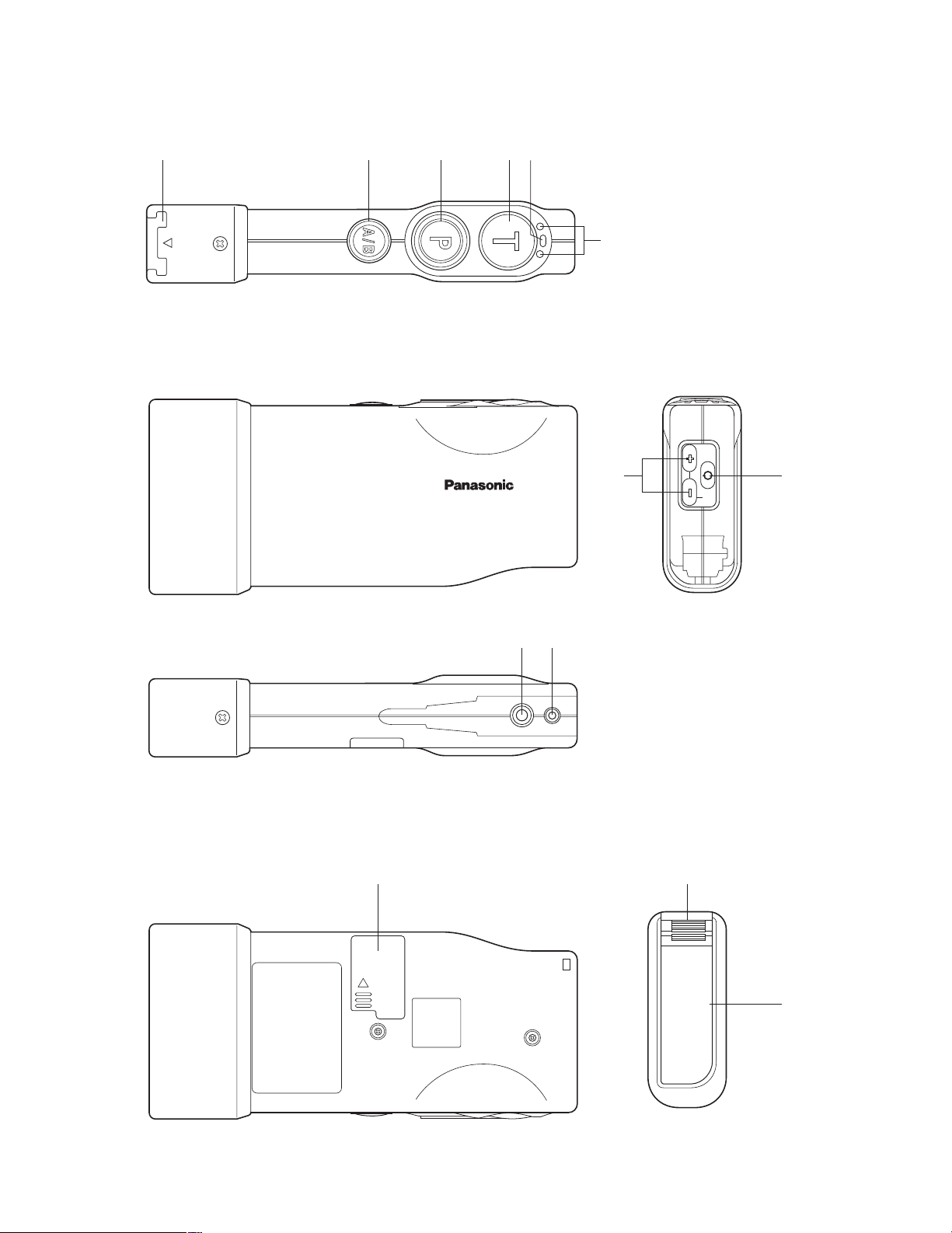
q w e r t
NAMES & FUNCTIONS
EJECT
WX-CT2020
AB
o !0
y
u
PWRVOL
i
!1 q
!2

5
q Battery Lock [EJECT]
When removing the battery, slide out the lock.
When loading a new battery, insert the battery until the
lock clicks.
w A/B Channel Selection Button [A/B]
This button switches frequencies from Channel A to B
and vice versa. The channel indicator
y displays the
selected channel in red (A) or green (B).
e Page Button [P]
This button controls communications with store personnel.
While the button is held down in the Page PTT mode,
you can speak to store personnel. When the button is
pressed in the Page Lock mode, you can speak to the
store personnel until you press a button a second time.
When the button is released, you can hear the communication among store personnel.
r Talk Button [T]
This button controls communications with the customer.
While the button is held down in the Talk PTT mode, you
can speak to the customer who is at the menu board.
When the button is pressed in the Talk Lock mode, you
can speak to the customer until you press the button a
second time.
When the button is released, you can hear the customer.
t Power Indicator
The indicator shows the status as follows.
Green ON: Power is supplied, and the unit is oper-
ating.
Red ON: The battery requires recharging.
Red Blink: The channel selector (refer to p. 7) is set
to a wrong position.
y Channel Indicator
While lighting in red or green, this indicator shows
which channel is in operation.
Red lighting: Channel A is selected.
Green lighting: Channel B is selected.
Red blinking: Channel A is being selected, and either
the Talk or Page mode is activated.
Green blinking: Channel B is being selected, and
either the Talk or Page mode is activated.
u Volume Control Buttons [VOL ▲▼]
Pressing the respective buttons will increase or
decrease the sound level.
i Power Button
Pressing this button for one second will turn the order
taker unit on or off.
o Earphone Input Jack
This jack is used for connection with WX-C1027A
Headset.
!0 Microphone Input Jack
This jack is used for connection with WX-C1027A
Headset.
!1 Switch Pocket
Do not open the lid of this pocket. Should be opened
only by qualified service personnel or system installers.
!2 Battery (Optional accessory)
Refer to p. 3 PRECAUTIONS.
 Loading...