

Panasonic of North America 9TAK SAP14 User Manual

1.9GHz Wireless Access Point
K-SAP14

CONTENTS
Important safety instructions
Major operating controls and their functions
Operating procedures
Functions and settings
Connections
Precautions for installation
Installation
Specifications
Accessories

FCC CAUTION
to correct the interference at his own expense.
absence of information to transmit or operational failure.
Changes or modifications not expressly approved by the party responsible for compliance could void the
user’s authority to operate the equipment.
This device complies with part 15 of the FCC Rules. Operation is subject to the following two conditions: (1)
This device may not cause harmful interference, and (2) this device must accept any interference received,
including interference t hat may cause undesired operation.
Note: This equipment has been tested and found to comply with the limits for a Class A digital device,
pursuant to part 15 of the FCC Rules. These limits are designed to provide reasonable protection against
harmful interference when the equipment is operated in a commercial environment. This equipment
generates, uses, and can radiate radio frequency energy and, if not installed and used in accordance with
the instruction manual, may cause harmful interference to radio communications. Operation of this
equipment in a residential area is likely to cause harmful interference in which case the user will be required
Compliance with FCC requirement 15.407(c)
Data transmission is always initiated by software, which is the passed down through the MAC, through the
digital and analog baseband, and finally to the RF chip. Several special packets are initiated by the MAC.
These are the only ways the digital baseband portion will turn on the RF transmitter, which it then turns off
at the end of the packet. Therefore, the transmitter will be on only while one of the aforementioned packets
is being transmitted. In other words, this device automatically discontinue transmission in case of either
Radio Frequency (RF) Exposure Warning
This equipment complies with FCC radiation exposure limits set forth for an uncontrolled environment and
meets the FCC radio frequency (RF) Exposure Guidelines. This equipment should be installed and
operated keeping the radiator at least 20cm or more away from person’s body.
MEDICAL:
Consult the manufacturer of any personal medical devices, such as pacemakers, to determine if they are
adequately shielded from external RF (radio frequency) energy. The unit operates in the frequency range of
1.92 GHz to 1.93 GHz.
Do not use the unit in health care facilities if any regulations posted in the area instruct you not to do so.
Hospitals or health care facilities may be using equipment that could be sensitive to external RF (radio
frequency) energy.
Notice
FCC ID can be found on the bottom of the units.
WARNING:
- The mains plug or an appliance coupler shall remain readily operable.
- To prevent injury, this apparatus must be securely attached to the floor/wall in accordance with the
installation instructions.
- The connections should comply with local electrical code.
- The installation shall be carried out in accordance with all applicable installation rules.
- To reduce the risk of fire or electric shock, do not expose this apparatus to rain or moisture.
- The apparatus should not be exposed to dripping or splashing and that no objects filled with liquids, such
as vases, should be placed on the apparatus.
- All work related to the installation of this product should be made by qualified service personnel or system
installers.
- This product has no power switch. When turning off the power, disconnect the power supply from the PoE
device.
CAUTION:
Before attempting to connect or operate this product, please read the label on the bottom.
The model number and serial number of this product may be found on the surface of the unit.
You should note the model number and serial number of this unit in the space provided and retain this
book as a permanent record of your purchase to aid identification in the event of theft.
Model No.
Serial No.

Important safety instructions
1) Read these instructions.
2) Keep these instructions.
3) Heed all warnings.
4) Follow all instructions.
5) Do not use this apparatus near water.
6) Clean only with dry cloth.
7) Do not block any ventilation openings. Install in accordance with the manufacturer's instructions.
8) Do not install near any heat sources such as radiators, heat registers, stoves, or other apparatus (including
amplifiers) that produce heat.
9) Protect the power cord from being walked on or pinched particularly at plugs, convenience receptacles, and
the point where they exit from the apparatus.
10) Only use attachments/accessories specified by the manufacturer.
11) Use only with the cart, stand, tripod, bracket, or table specified by the
manufacturer, or sold with the apparatus. When a cart is used, use caution
when moving the cart/apparatus combination to avoid injury from tip-over.
12) Unplug this apparatus during lightning storms or when unused for long periods of time.
13) Refer all servicing to qualified service personnel. Servicing is required when the apparatus has been
damaged in any way, such as power-supply cord or plug is damaged, liquid has been spilled or objects
have fallen into the apparatus, the apparatus has been exposed to rain or moisture, does not operate
normally, or has been dropped.

Major operating controls and their functions
6
1
3
2
4 5

[1]POWER indicator
(Green/Red)
This LED lights green when the power is on and this unit is receivable under normal conditions.
This LED lights as follows to indicate other states:
E2 signal output provided: lighting red ( For ONLR Alert)
[2]LINK indicator [OPERATE]
(Green/Red)
This LED lights green when connecting with a receiver.
This LED lights as follows to indicate other states:
E2 signal output provided: lighting red ( For ONLR Alert)
[3]MODE indicator
(Green/Yellow/Red)
This LED lights green when select for sound broadcast state
This LED lights yellow when select for ONLY alert state.
(This LED lights yellow when system error)
[4] Ethernet connector
An RJ-45 type connector of this unit is based on our original system and electrical specifications. Never connect this terminal to a
LAN connector that is compatible with Ethernet and PoE (Power over Ethernet).
[5]Control terminals
8-pin and 7-pin Euro blocks are used.
The following terminals are equipped.
E1 CNT: provides E1 signal * output controlled by K-SAP14.
E2 CNT: provides E2 signal * output controlled by K-SAP14.
* Those are available when K-SAP14 is used. Settings of E1 and E2 are performed with K-SAP14.
E2 ACK: connects acknowledge signals responding to E2 output.
PAGE MUTE: provides make signal inputs externally when the paging function is used.
RS-232C: is used to control this unit via communication from an external device.
LINK button: provides make signal inputs externally when the external link button is used.
Alert notification button; provides make signal inputs externally when the external Alert notification button is used.
[6]DIP Switches
Two DIP switches are used.
DIP switch 1 can select the operation mode of each function equipped in this unit.
The settings of this switch are updated at the time of turning on the power.
From No.1 to No7 of DIP switch 2 are used for selection of group ID.
(It is used at the time of installation of DECT-AP and a receiver.)
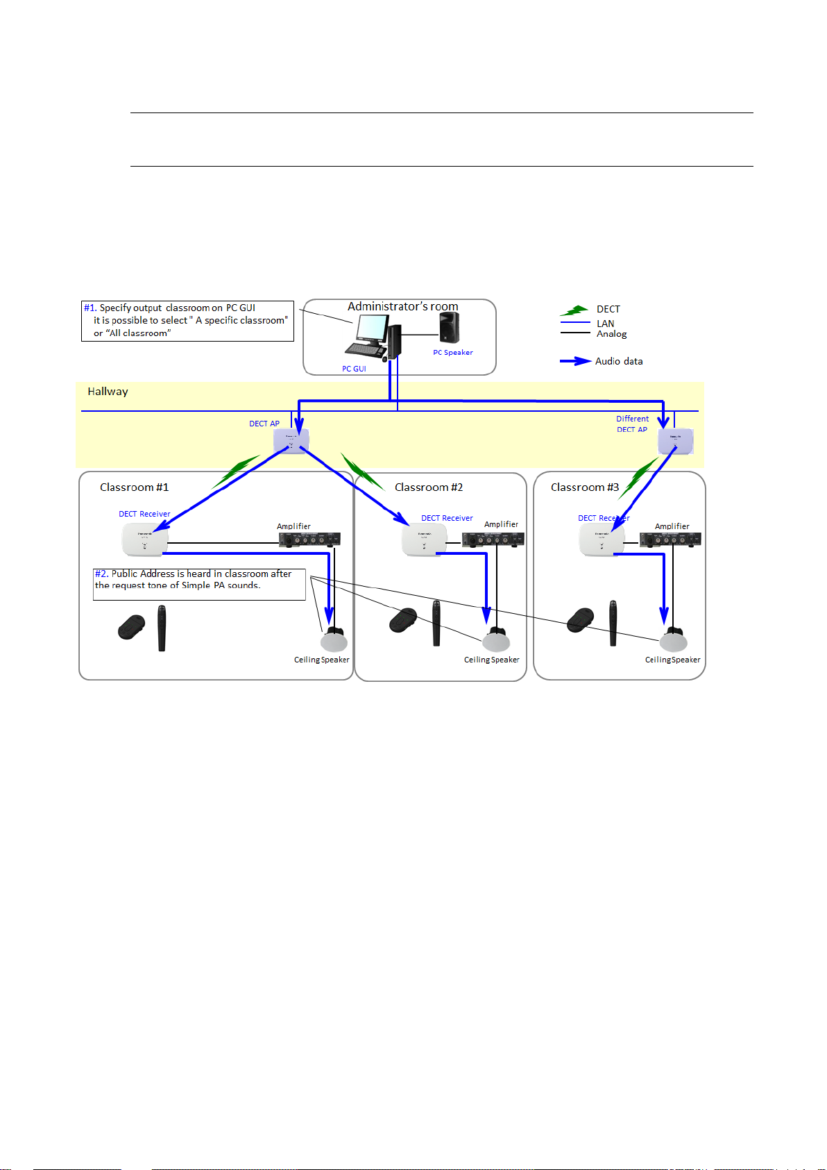
Operating procedures
Operation of Simple PA.
1. Specify output classroom on PC GUI it is possible to select "A specific classroom" or "All classroom"
2. Public Address is heard in classroom after the request tone of Simple PA sounds.
 Loading...