

Panasonic of North America 96NKX UDS124 User Manual
Model No.
KX-UDS124
DECT 6.0 Cell Station Unit (SIP)
Installation Guide
Thank you for purchasing this Panasonic product.
Please read this manual carefully before using this product and save this manual for future use.
KX-UDS124: Software File Version 01.000 or later

Table of Contents
Table of Contents
1 For Your Safety ........................................................................................3
2 Overview ...................................................................................................9
3 Installing the SIP Cell Stations .............................................................15
3.1 Overview of SIP Cell Stations ........................................................................................15
3.2 Connecting SIP Cell Stations .........................................................................................17
3.3 Wall Mounting ..................................................................................................................19
3.4 Basic Network Configuration .........................................................................................21
4 Deployment Procedure ..........................................................................25
4.1 Overview ..........................................................................................................................25
4.2 Site Planning ...................................................................................................................27
4.3 Site Survey .......................................................................................................................34
4.4 CS Registration ...............................................................................................................41
4.5 Tree Survey ......................................................................................................................43
4.6 Configuration ...................................................................................................................45
4.7 PS Registration ...............................................................................................................47
4.8 PS Area Check .................................................................................................................51
5 Troubleshooting .....................................................................................52
6 Appendix .................................................................................................54
2 Installation Guide
WARNING
CAUTION
WARNING
1 For Your Safety
1 For Your Safety
To prevent personal injury and/or damage to property, be sure to observe the following safety precautions.
The following symbols classify and describe the level of hazard and injury caused when this unit is
operated or handled improperly.
This notice means that misuse could result in
death or serious injury.
This notice means that misuse could result in injury
or damage to property.
The following types of symbols are used to classify and describe the type of instructions to be
observed.
This symbol is used to alert users to a specific operating procedure that must not be performed.
This symbol is used to alert users to a specific operating procedure that must be followed in
order to operate the unit safely.
• Do not connect or disconnect the AC plug with wet hands.
• Do not touch the SIP-CS, AC adaptor, or AC adaptor cord during a lightning storm.
• Do not allow anything to rest on the AC adaptor cord or LAN cable. Do not locate the SIP-CS where the
AC adaptor cord or LAN cable may be stepped on or tripped on.
• When installing or testing a SIP-CS with an external AC adaptor, the AC adaptor should be plugged into
a wall outlet or floor-mounted AC outlet. Do not connect the AC adaptor to a ceiling-mounted AC outlet, as
the weight of the adaptor may cause it to become disconnected.
• Make sure that you do not short the battery or cables.
• Never attempt to insert wires, pins, etc. into the vents or other holes of the SIP-CS.
• Do not splash water on the AC adaptor or the power cord, nor get them wet. Doing so can result in fire,
electric shock, or injury. If they do get wet, immediately disconnect the AC adaptor and power cord, and
contact an authorized service center.
• Do not touch the AC adaptor for extended periods of time. Doing so can lead to low-degree burns.
• Do not make power connections that exceed the ratings for the AC outlet or power equipment. If the power
rating of a surge protector, etc. is exceeded, it can cause a fire due to heat buildup.
• Care should be taken so that objects do not fall onto, and liquids are not spilled into, the SIP-CS. Do not
subject the SIP-CS to excessive smoke, dust, moisture, mechanical vibration, shock, or direct sunlight.
• Do not place heavy objects on top of the SIP-CS.
• Do not mount the SIP-CS in a manner other than that described in this manual.
Installation Guide 3
CAUTION
1 For Your Safety
• The SIP-CS must only be installed and serviced by qualified service personnel. The SIP-CS should be
used as-is from the time of purchase; it should not be disassembled or modified. Disassembly or
modification can cause a fire, electric shock, or damage to the SIP-CS.
• Make sure that the wall that the SIP-CS will be attached to is strong enough to support the SIP-CS (approx.
330 g [11.6 oz]). If not, it is necessary for the wall to be reinforced.
• Only use the wall-mounting equipment (screws, washers, wall mounting plate) included with the SIP-CS.
• When the SIP-CS is no longer in use, make sure to detach it from the wall.
• Disconnect the SIP-CS from the AC outlet, disconnect the LAN cable, and contact the dealer if:
– The AC adaptor cord or AC plug becomes damaged or frayed.
– The SIP-CS is exposed to rain, water, or any other liquid.
– The SIP-CS is dropped or damaged.
– Internal components are exposed due to damage.
– The SIP-CS does not operate properly.
– Performance deteriorates.
• Disconnect the SIP-CS from the AC outlet and disconnect the LAN cable if the SIP-CS emits smoke, an
abnormal smell, or makes unusual noise. These conditions can cause fire or electric shock. Confirm that
smoke has stopped and contact an authorized service center.
• Clean the AC plug periodically with a soft, dry cloth to remove dust and other debris.
• If using an AC adaptor, use the optional AC adaptor KX-A239 (PQLV206YB), KX-A239X(PQLV206YB).
• If damage to the SIP-CS exposes any internal parts, immediately disconnect the cable or cord. If the power
is supplied from the network to the SIP-CS (Power-over-Ethernet), disconnect the Ethernet cables.
Otherwise, disconnect the AC adaptor cord. Then return the SIP-CS to a service center.
• The SIP-CS should only be connected to a power supply of the type shown on the label on the SIP-CS.
• Completely insert the AC adaptor/power plug into the AC outlet. Failure to do so may cause electric shock
and/or excessive heat resulting in a fire.
• Do not stretch or bend the cables. Also, do not allow anything to rest on the cables.
• Do not bundle cables that are connected to the SIP-CS with the AC power cords of machines located
nearby.
• To prevent malfunction, deformity, overheating, rust, and discolouration, do not install or place equipment
in the following types of locations:
– Locations where air ventilation is poor.
– Locations that may be exposed to sulphurous gas, such as near hot springs.
– Near devices that emit heat, such as heaters.
– Near devices that emit electromagnetic noise, such as radios or televisions.
– Near devices that emit high-frequency noise, such as sewing machines or welders.
• The SIP-CS and the cables should never be placed near or over a radiator or other heat source.
• The SIP-CS should not be placed outdoors (use indoors).
• The SIP-CS should not be placed near high-voltage equipment.
4 Installation Guide

1 For Your Safety
• The SIP-CS should not be placed on a metal object.
• The SIP-CS should be kept free of dust, moisture, high temperature (more than 40 °C [104 °F]), low
temperature (less than 0 °C [32 °F]), and vibration, and should not be exposed to direct sunlight.
• When driving the screws into the wall, be careful to avoid touching any metal laths, wire laths or metal
plates in the wall.
• Use cables that are fire-resistant or fireproof.
• Make sure the cables are securely fastened to the wall.
• The AC adaptor is used as the main disconnect device. Ensure that the AC adaptor is located near the
SIP-CS and is easily accessible.
• Disconnect the AC adaptor cord and all cables from the SIP-CS before cleaning. Clean the SIP-CS with a
soft, dry cloth. Do not use liquid, aerosol cleaners, abrasive powders, or chemical agents to clean the
SIP-CS.
• When left unused for a long period of time, disconnect the SIP-CS from the AC outlet. When the SIP-CS
receives power from a PoE power supply, disconnect the LAN cable.
• Medical—consult the manufacturer of any personal medical devices, such as pacemakers, to determine
if they are adequately shielded from external RF (radio frequency) energy. (The SIP-CS operates in the
frequency range of 1920 MHz to 1930 MHz, and the output peak power level is less than 0.12 W.) Do not
use the SIP-CS in health care facilities if any regulations posted in the area instruct you not to do so.
Hospitals or health care facilities may be using equipment that could be sensitive to external RF (radio
frequency) energy.
• To ensure the security of private conversations, only connect the SIP-CS to a secure network.
• To prevent unauthorized access, only connect the SIP-CS to a network that is properly managed.
• Make sure all personal computers that are connected to the SIP-CS employ up-to-date security measures.
• To avoid unauthorized access and possible abuse of your phone system, we strongly recommend:
– Keeping the password secret.
– Changing your password regularly.
– Selecting a complex, random password that cannot be easily guessed.
• Maintain the distances listed in "Required Distances between Equipment" in the Installation Guide between
equipment in order to prevent noise, interference or the disconnection of a conversation. (The distance
may vary depending on the environment.)
Notice
SAFETY REQUIREMENTS
• Before connecting the SIP-CS, confirm that the SIP-CS supports the intended operating environment.
• If the SIP-CS does not operate properly, disconnect the AC adaptor cord and LAN cable, then connect
again.
• The SIP-CS may not operate in the event of a power failure.
• Do not move the SIP-CS while it is in use.
• Satisfactory operation, interoperability, and compatibility cannot be guaranteed with all equipment
connected to the SIP-CS, nor with all services provided by telecommunications providers over networks
connected to the SIP-CS.
SECURITY REQUIREMENTS
• Privacy of communications may not be ensured when using the wireless systems.
• Keep a copy of all important data (such as your network information) before sending the machine for
repair.
Installation Guide 5

1 For Your Safety
• The SIP-CS can store your private/confidential information. To protect your privacy/confidentiality, we
recommend that you initialize the SIP-CS to erase all user data and restore the factory default settings
before you dispose, transfer or return the SIP-CS.
6 Installation Guide

Additional Information
F.C.C. AND INDUSTRY CANADA RELEVANT INFORMATION
CAUTION
Any changes or modifications not expressly approved by the party responsible for compliance could void
the user's authority to operate this device.
Privacy of communications may not be ensured when using this unit.
Notice
FCC ID can be found on the back of this unit.
Note
This equipment has been tested and found to comply with the limits for a Class B digital device, pursuant
to Part 15 of the FCC Rules. These limits are designed to provide reasonable protection against harmful
interference in a residential installation. This equipment generates, uses, and can radiate radio frequency
energy and, if not installed and used in accordance with the instructions, may cause harmful interference
to radio communications. However, there is no guarantee that interference will not occur in a particular
installation. If this equipment does cause harmful interference to radio or television reception, which can
be determined by turning the equipment off and on, the user is encouraged to try to correct the interference
by one or more of the following measures:
• Reorient or relocate the receiving antenna.
• Increase the distance between the equipment and receiver.
• Connect the equipment to an outlet on a circuit different from that to which the receiver is connected.
• Consult the dealer or an experienced radio/TV technician for help.
1 For Your Safety
Some wireless telephones operate at frequencies that may cause interference to nearby TVs and VCRs.
To minimize or prevent such interference, the base of the wireless telephone should not be placed near
or on top of a TV or VCR. If interference is experienced, move the wireless telephone further away from
the TV or VCR. This will often reduce, or eliminate, interference.
RF Exposure Warning:
This product complies with FCC/IC radiation exposure limits set forth for an uncontrolled environment. To
comply with FCC/IC RF exposure requirements, this product must be installed and operated in accordance
with the provided instructions. The installed unit requires a minimum 20 cm (8 inches) of spacing between the
antenna and a person’s body (excluding hands, wrists and feet) during wireless modes of operation.
This transmitter must not be co-located or operated in conjunction with any other antennas or transmitters.
For Users in Canada Only
This Class B digital apparatus complies with Canadian ICES-003.
Note
Operation is subject to the following two conditions: (1) this device may not cause interference, and (2) this
device must accept any interference, including interference that may cause undesired operation of the
device.
Privacy of communications may not be ensured when using this telephone. Some wireless telephones
operate at frequencies that may cause interference to nearby TVs and VCRs. To minimize or prevent such
interference, the base of the wireless telephone should not be placed near, or on top of, a TV or VCR. If
Installation Guide 7

1 For Your Safety
interference is experienced, move the wireless telephone further away from the TV or VCR. This will often
reduce, or eliminate, interference.
8 Installation Guide

2 Overview
2 Overview
Outline
This document describes the installation, deployment, configuration of a SIP-based DECT system. In this
system, SIP-based DECT Portable Stations are used together with SIP-CSs.
Related Documentation
Administrator Guide for KX-UDS124
Describes the programming and maintenance of the SIP-CS.
Please refer to the following web site for more information:
http://panasonic.net/pcc/support/sipphone
Terminology
Air Sync Group
Air Synchronisation Group. To obtain steady Air Synchronisation over a wide area, it is necessary to create
Air Sync Groups.
Air Sync Master CS
Primary Clock Master of an Air Sync Group. Each Air Sync Group must have a unique Air Sync Master.
Air Sync Secondary Master CS
Secondary Clock Master of an Air Sync Group
DECT
Digital Enhanced Cordless Telecommunication
Handover
Allows you to move between CS coverage areas during a conversation without disrupting the call. This is only
possible within the same Air Sync Group.
IPEI
International Portable Equipment Identity Decimal, 12-digit, globally unique identification code of PSs.
Specified in ETSI EN 300 175-6.
Migration
Allows you to use the S-PS at another system (site) which was registered beforehand.
Primary CS
Primary CS for Air Synchronisation
Roaming
Allows you to move between coverage areas of SIP-CSs in other Air Sync Groups when the S-PS is idle.
S-PS
SIP-CS compatible Portable Station/Handset
Secondary CS
Secondary CS for Air Synchronisation
SIP-CS
SIP Cell Station
Super Master CS
Master CS of Air Sync Group 1. This CS manages configuration for the whole system.
Tree Survey
Procedure to obtain a steady Air Synchronisation tree.
Installation Guide 9
S-PS
Switching
Hub
SIP-CS
Super Master
(Air Sync Master 1)
SIP-CS
Air Sync Group 1
Air Sync Group 1
S-PS
Handover
SIP Server
SIP-CS
SIP Server
SIP-CS
Air Sync Group 2
Air Sync Group 2
Switching
Hub
SIP-CS
SIP-CS
S-PS
Roaming
Internet
2 Overview
System Overview
The SIP-CS can be connected to a SIP server via a LAN and supports S-PSs for making calls. The SIP-CS
allows for easy and cost-saving installation using an existing IP network infrastructure. Air synchronisation
technology is used for synchronising each SIP-CS.
The SIP-CS provides the following:
– Wireless systems using a converged voice and data network infrastructure.
– Wireless branch offices and wireless solutions by long distance installation on larger premises when
located on the same network.
– Reliable wireless communication using DECT technology over an IP network.
– High quality voice communication.
– Easy maintenance using Air Download.
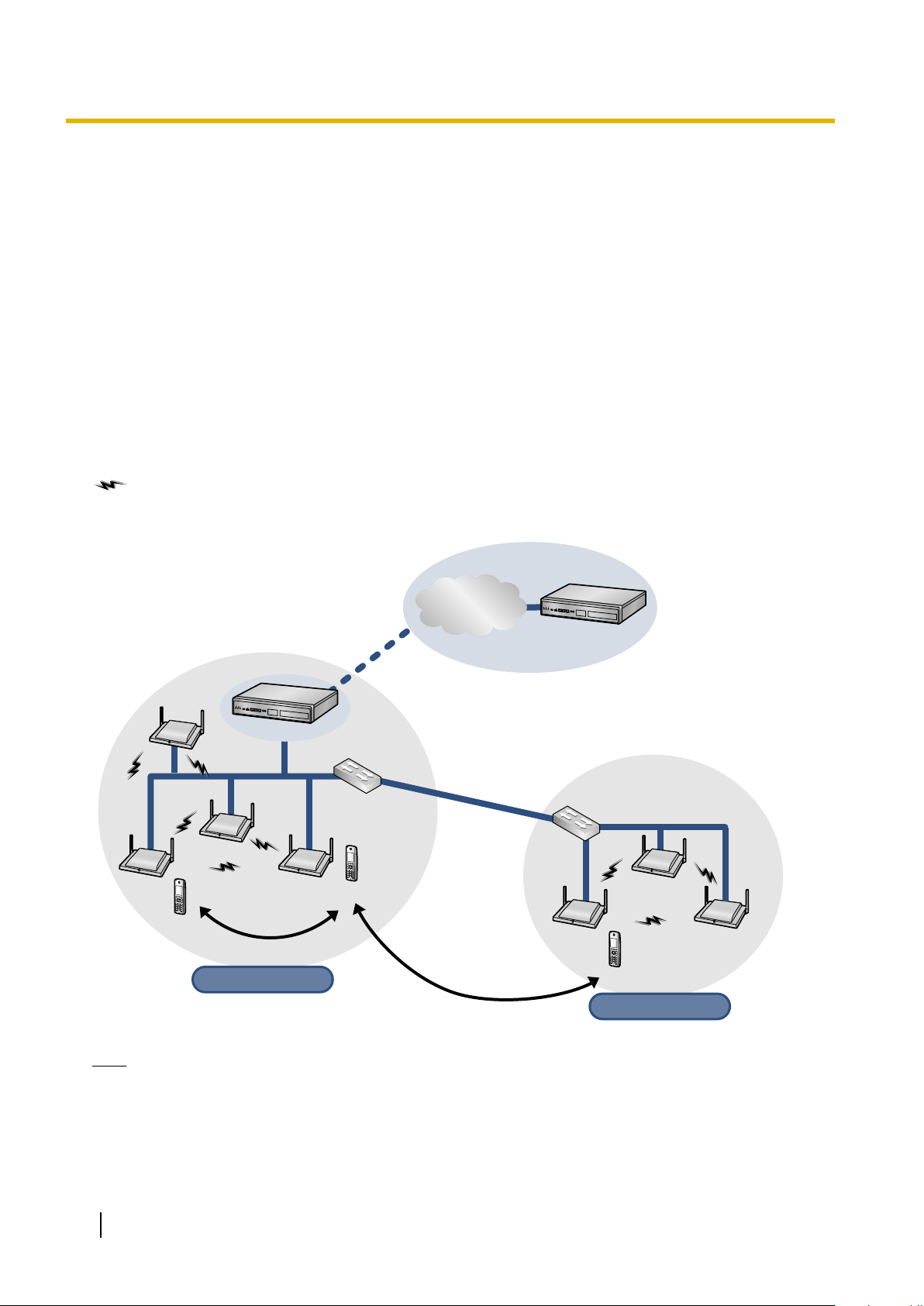
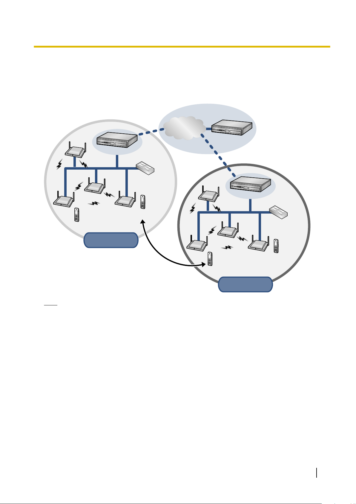
The following is an example of SIP-CS installation using an IP network.
To obtain steady Air Synchronisation, create two or more Air Sync Groups to cover a wide area, as shown
below.
: Handover is working.
Roaming
Note
• You can move between the coverage areas of SIP-CSs during a conversation, without disrupting the
call. This is called "Handover" and is only possible within the same Air Sync Group. You cannot move
between Air Sync Groups during a conversation. You can only move between Air Sync Groups when
in idle status. This is called "Roaming".
• Each Air Sync Group requires an Air Sync Master CS.
10 Installation Guide
S-PS
Switching
Hub
SIP-CS
Super Master
(Air Sync Master 1)
SIP-CS
Air Sync Group 1
Air Sync Group 1
in Site A
in Site A
S-PS
SIP-CS
S-PS
Switching
Hub
SIP-CS
Super Master
(Air Sync Master 1)
SIP-CS
Air Sync Group 1
Air Sync Group 1
in Site B
in Site B
S-PS
SIP Server
SIP-CS
SIP Server
Migration
Internet
SIP Server
2 Overview
• The system requires one Super Master CS to control the system as a whole. The Air Sync Master CS
of Air Sync Group 1 becomes the Super Master CS.
• All SIP-CSs of the same model consist of the same hardware and same firmware, but each SIP-CS's
role (Master/Slave) is decided by its settings.
Migration
Note
• You can use a S-PS in other systems (sites), if you register it to each system beforehand. This is called
"Migration". You can register up to 4 systems to a S-PS.
• A system at a different site connected by a dedicated line (such as an IP-VPN), which shares a Super
Master CS, is considered part of the same system.
Installation Guide 11
SIP Server
S-PS
S-PS
SIP (REGISTER)(2)
SIP-CS(1)
SIP-CS(2)
(1)
Move(3)
(4)
SIP (REGISTER)(5)
SIP Server
S-PS S-PS
SIP/RTP
(4)
Handover
(7)
Handover
S-PS
RTP
RTP
(1)
(2)
(3)
(5)
(6)
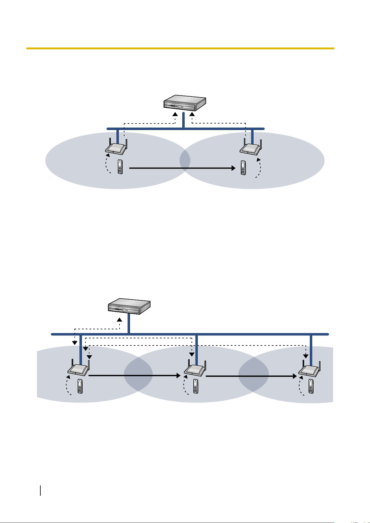
2 Overview
SIP Signalling and Media Stream Control Overview
Moving while in standby mode
(1) The S-PS requests Location Registration from SIP-CS(1).
(2) SIP-CS(1) requests SIP Registration from the SIP server.
(3) The S-PS moves from coverage area of SIP-CS(1) to the coverage area of SIP-CS(2).
(4) The S-PS requests Location Registration from SIP-CS(2).
(5) SIP-CS(2) requests SIP Registration from the SIP server.
SIP registration is executed each time the S-PS performs location registration while it is idle.
Moving while talking
(1) The S-PS requests Location Registration to SIP-CS(1), and then the S-PS starts the call.
(2) The S-PS moves from the coverage area of SIP-CS(1) to the coverage area of SIP-CS(2).
(3) The S-PS requests Location Registration to the SIP-CS(2).
(4) RTP is transferred from SIP-CS(1) to SIP-CS(2).
12 Installation Guide
Super
Master CS
Air Synchronisation Group 1 Air Synchronisation Group 2 Air Synchronisation Group n
Air Sync
Master CS
Air Sync
Master CS
Slave CS
Slave CS
Slave CS
Slave CS
Slave CS
Slave CS
Slave CS
Slave CS
Slave CS
2 Overview
(5) The S-PS moves from the coverage area of SIP-CS(2) to the coverage area of SIP-CS(3).
(6) The S-PS requests Location Registration to the SIP-CS(3).
(7) RTP is transferred from SIP-CS(1) to SIP-CS(3).
SIP signalling and the media stream are sent between the SIP-CS currently in use and the SIP-CS that was
being used when the call started.
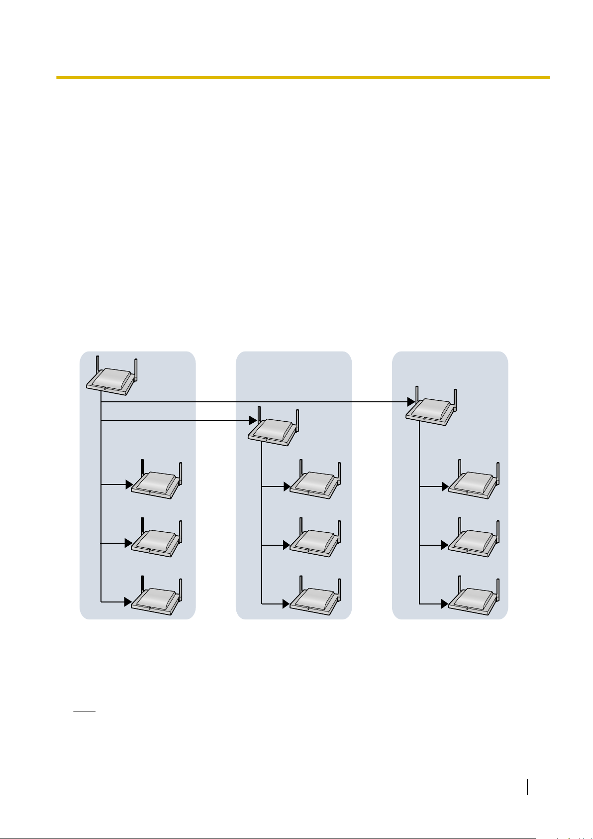
System Configuration
The Air Sync Master CS of Air Sync Group 1 is the most important SIP-CS. It is called the Super Master CS.
The Super Master CS has the following roles:
• Portal for all settings.
• Management of the synchronisation tree of all SIP-CSs.
• Distribution of configuration data via Web user interface programming or configuration file programming.
• Distribution of SIP-CS and S-PS firmware data to all SIP-CSs in the system.
• Distribution of imported phonebook data to all SIP-CSs in the system.
Data flow of SIP-CSs
1. The Super Master distributes data to each Air Sync Master.
2. Each Air Sync Master distributes the data to all Slave CSs in the Air Sync Group. Also, the Super Master
distributes the data to all Slave CSs in Air Sync Group 1.
Note
• Data will be distributed until all Slave CSs in all Air Sync Groups receive the data.
• Data is distributed in the following situations:
– When the Super Master CS is started.
Installation Guide 13

2 Overview
– When All Save is performed through the Web user interface.
– When Timed forwarding update is set.
– When Timed phonebook importing is set.
System Specifications
Item Maximum Number per System
S-PS 255
SIP-CS
Air Sync Group 8
Super Master CS 4
Note
A S-PS can be registered to up to 4 SIP-CS systems.
(32 SIP-CSs per Air Sync Group)
128
14 Installation Guide
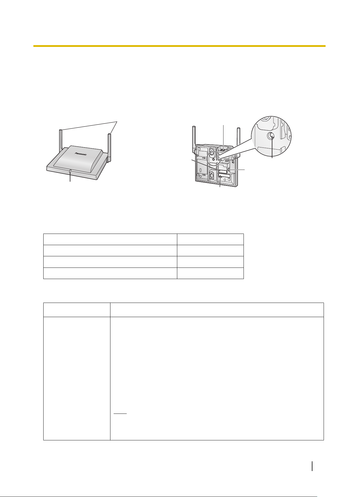
3 Installing the SIP Cell Stations
LED
Antennas
CS ID Number
(ID: xxxxxxxxxx)
RJ45 Modular
RESET Switch
DC Jack
MAC Address
3.1 Overview of SIP Cell Stations
Names and Locations
3 Installing the SIP Cell Stations
Unpacking
Unpack the box and check the items below:
SIP Cell Station 1
Wall Mounting Plate 1
Screws 2
Washers 2
LED Indications
SIP-CS State
General Operation
• OFF: Power Off/SIP-CS Software downloading
• Green ON: Stand-by (no active calls)
• Slow Green Flashing: Talk (active calls)
• Moderate Green Flashing: Busy
• Red ON: Fault
• Slow Red Flashing: Out of Service/Starting up (data link establishment ® Air
Synchronisation)
• Moderate Red Flashing: Starting up (power on ® data link establishment)
• Amber ON: Stand-by (unstable synchronisation [no active calls])
• Slow Amber Flashing: Talk (unstable synchronisation [active calls])
• Moderate Amber Flashing: Busy
Description
*1
*1
(unstable synchronisation)
Note
LED flashing patterns are as follows:
• Slow Flashing: 60 times per minute
• Moderate Flashing: 120 times per minute
Installation Guide 15

3 Installing the SIP Cell Stations
SIP-CS State Description
Site Survey Mode
*1
All voice channels are occupied.
• Red and green alternate flashing: Site Survey Master mode
• Green flashing: The site survey signal being received is good
• Orange flashing: The site survey signal being received is not good
• Red flashing: The site survey signal has been lost
• Slow red flashing: No site survey signal (after receiving IP address)
• Moderate red flashing: No site survey signal (before receiving IP address)
16 Installation Guide
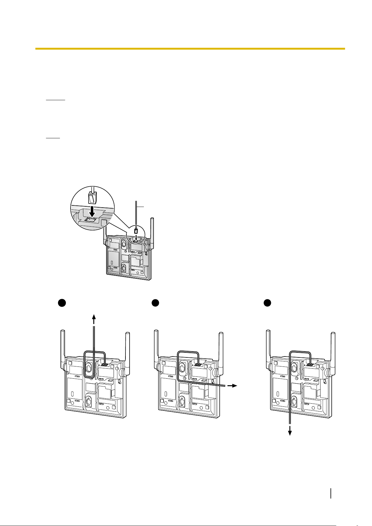
3.2 Connecting SIP Cell Stations
Ethernet Cable
To a Switching Hub
To a
Switching
Hub
To a Switching Hub
1 2 31
Connecting a SIP-CS to a LAN
Notice
• Connect the SIP-CSs to the LAN only after completing network settings. For details about network
settings, see "Configuring Network Settings for Super Master CS" in "4.3 Site Survey".
• When connecting a SIP-CS to the LAN, connect it to a switching hub.
Note
• Use an Ethernet straight cable with an RJ45 connector to connect the SIP-CS to a switching hub. The
cable should be a 10BASE-T/100BASE-TX CAT 5 (Category 5) or higher cable, and the diameter of
the cable must be 6.5 mm or less.
• It is possible to connect the SIP-CS to the LAN while registering the SIP-CS to the SIP server.
1. Connect the cable to the SIP-CS.
3 Installing the SIP Cell Stations
2. Pass the cable through the groove of the SIP-CS in one of the following three ways.
3. Connect the other end of the cable to the switching hub.
Installation Guide 17
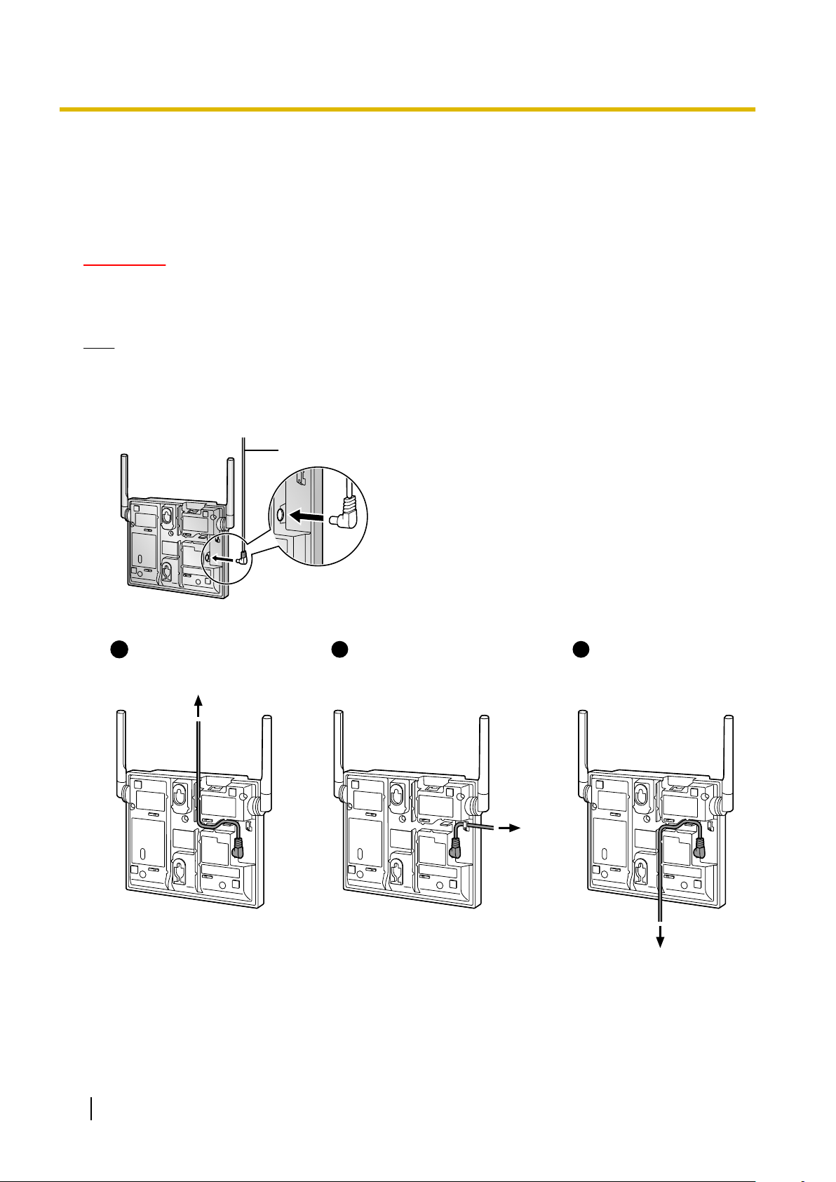
AC Adaptor Cord
To AC Adaptor
KX-A239
2
To AC Adaptor
KX-A239
3
To AC Adaptor
KX-A239
11
3 Installing the SIP Cell Stations
Connecting an AC Adaptor to a SIP-CS
SIP-CSs comply with the IEEE 802.3af Power-over-Ethernet (PoE) standard. If PoE is available on your
network, these SIP-CSs can receive the necessary power supply from the network through the network cable.
In this case, no AC adaptor is needed for the SIP-CSs.
However, if PoE is not available, you will need to connect an AC adaptor to the SIP-CS.
WARNING
When installing or testing a SIP-CS with an external AC adaptor, the AC adaptor should be plugged
into a wall outlet or floor-mounted AC outlet. Do not connect the AC adaptor to a ceiling-mounted
AC outlet, as the weight of the adaptor may cause it to become disconnected.
Note
Use only the optional AC adaptor KX-A239 (PQLV206YB) or KX-A239X (PQLV206YB) for the SIP-CS.
1. Connect the AC adaptor cord to the SIP-CS.
2. Pass the cord through the groove of the SIP-CS in one of the following three ways.
3. Connect the AC adaptor to an AC outlet.
18 Installation Guide
 Loading...