

Panasonic of North America 96NKX NCP0158 User Manual
Quick Installation Guide
DECT 6.0 8-Channel IP Cell Station Unit
Model No.
KX-NCP0158
Thank you for purchasing a Panasonic DECT 6.0 8-Channel IP Cell Station Unit.
Please read this manual carefully before using this product and save this manual for future use.
Document Version: 2009-06
SAVE THESE INSTRUCTIONS
Important Information
Important Information
Safety Notices
Please observe the safety notices in this manual in order to avoid danger to users or other people, and prevent
damage to property.
The notices are classified as follows, according to the severity of injury or damage:
WARNING
CAUTION
This notice means that misuse could result in death or serious injury.
This notice means that misuse could result in injury or damage to
property.
WARNING
SAFETY REQUIREMENTS
• Make sure that the wall that the unit will be attached to is strong enough to support the unit (approx.
440 g [16 oz]). If not, it is necessary for the wall to be reinforced.
• Only use the wall-mounting equipment (screws, washers, wall mounting plate) included with the unit.
• When this unit is no longer in use, make sure to detach it from the wall.
• Do not connect or disconnect the AC plug with wet hands.
• Disconnect the unit from the AC outlet, disconnect the LAN cable, and contact the dealer if:
– The AC adaptor cord, AC cord, AC plug, or DC extension cable (PQJA10200) becomes damaged
or frayed.
– The unit is exposed to rain, water, or any other liquid.
– The unit is dropped or damaged.
– Internal components are exposed due to damage.
– The unit does not operate properly.
– Performance deteriorates.
• Disconnect the unit from the AC adaptor/DC extension cable (PQJA10200), and LAN cable if the unit
emits smoke, an abnormal smell, or makes unusual noise. These conditions can cause fire or electric
shock. Confirm that smoke has stopped and contact an authorized service centre.
• Clean the AC plug periodically with a soft, dry cloth to remove dust and other debris.
• Do not touch the unit, AC adaptor, AC adaptor cord, AC cord, or DC extension cable (PQJA10200)
during a lightning storm.
• If using an AC adaptor, use only the optional AC adaptor KX-A421 (PSLP1662).
• Do not allow anything to rest on the AC adaptor cord, AC cord, DC extension cable (PQJA10200), or
LAN cable. Do not locate this unit where the AC adaptor cord, AC cord, DC extension cable
(PQJA10200), or LAN cable may be stepped on or tripped on.
CAUTION
SAFETY REQUIREMENTS
• The CS should be kept free of dust, moisture, high temperature (more than 40 °C [104 °F]), low
temperature (less than 0 °C [32 °F]), and vibration, and should not be exposed to direct sunlight.
• The CS should not be placed outdoors (use indoors).
• The CS should not be placed near high-voltage equipment.
• The CS should not be placed on a metal object.
• The DC jack cover poses a choking hazard. Keep the DC jack cover out of reach of children.
2 Quick Installation Guide Document Version 2009-06

Important Information
• When driving the screws into the wall, be careful to avoid touching any metal laths, wire laths or metal
plates in the wall.
• To prevent malfunction, deformity, overheating, rust, and discoloration, do not install or place
equipment in the following types of locations:
– Locations where air ventilation is poor.
– Locations that may be exposed to sulphurous gas, such as near hot springs.
– Near devices that emit heat, such as heaters.
– Near devices that emit electromagnetic noise, such as radios or televisions.
– Near devices that emit high-frequency noise, such as sewing machines or welders.
• Do not stretch or bend the cables. Also, do not allow anything to rest on the cables.
• Use cables that are fire-resistant or fireproof.
• The CS and the cables should never be placed near or over a radiator or other heat source.
• Do not bundle cables that are connected to the CS with the AC power cords of machines located
nearby.
• Make sure the cables are securely fastened to the wall.
• The AC adaptor is used as the main disconnect device. Ensure that the AC adaptor is located near the
unit and is easily accessible.
• Disconnect the AC adaptor cord and all cables from the unit before cleaning. Clean the unit with a soft,
dry cloth. Do not use liquid, aerosol cleaners, abrasive powders, or chemical agents to clean the unit.
• When left unused for a long period of time, disconnect the unit from the AC outlet. When the unit
receives power from a PoE power supply, disconnect the LAN cable.
• Medical—consult the manufacturer of any personal medical devices, such as pacemakers, to
determine if they are adequately shielded from external RF (radio frequency) energy. (The unit operates
in the frequency range of 1920 MHz to 1930 MHz, and the output peak power level is less than
0.125 W.) Do not use the unit in health care facilities if any regulations posted in the area instruct you
not to do so. Hospitals or health care facilities may be using equipment that could be sensitive to
external RF (radio frequency) energy.
Notice
SAFETY REQUIREMENTS
• Before connecting the unit, confirm that the unit supports the intended operating environment.
• If the unit does not operate properly, disconnect the AC adaptor cord and LAN cable, then connect
again.
• The unit may not operate in the event of a power failure.
• Do not move the unit while it is in use.
• Satisfactory operation, interoperability, and compatibility cannot be guaranteed with all equipment
connected to the unit, nor with all services provided by telecommunications providers over networks
connected to the unit.
SECURITY REQUIREMENTS
• Privacy of communications may not be ensured when using the wireless systems.
Document Version 2009-06 Quick Installation Guide 3

Important Information
Additional Information
F.C.C. REQUIREMENTS AND RELEVANT INFORMATION
CAUTION
Any changes or modifications not expressly approved by the party responsible for compliance could void
the user's authority to operate this device.
Note
This equipment has been tested and found to comply with the limits for a Class B digital device, pursuant
to Part 15 of the FCC Rules. These limits are designed to provide reasonable protection against harmful
interference in a residential installation. This equipment generates, uses, and can radiate radio frequency
energy and, if not installed and used in accordance with the instructions, may cause harmful interference
to radio communications. However, there is no guarantee that interference will not occur in a particular
installation. If this equipment does cause harmful interference to radio or television reception, which can
be determined by turning the equipment off and on, the user is encouraged to try to correct the interference
by one or more of the following measures:
• Reorient or relocate the receiving antenna.
• Increase the distance between the equipment and receiver.
• Connect the equipment to an outlet on a circuit different from that to which the receiver is connected.
• Consult the dealer or an experienced radio/TV technician for help.
Some wireless telephones operate at frequencies that may cause interference to nearby TVs and VCRs.
To minimize or prevent such interference, the base of the wireless telephone should not be placed near
or on top of a TV or VCR. If interference is experienced, move the wireless telephone further away from
the TV or VCR. This will often reduce, or eliminate, interference.
RF Exposure Warning:
This product complies with FCC radiation exposure limits set forth for an uncontrolled environment. To comply
with FCC RF exposure requirements, it must be installed and operated in accordance with the provided
instructions. The installed unit requires minimum 20 cm (8 inch) spacing must be provided between antenna
and all person's body (excluding extremities of hands, wrist and feet) during wireless modes of operation.
This transmitter must not be co-located or operated in conjunction with any other antenna or transmitter.
4 Quick Installation Guide Document Version 2009-06

Table of Contents
Table of Contents
1 Overview ...................................................................................................6
2 Procedure Overview ..............................................................................12
3 Site Planning ..........................................................................................14
4 Before Site Survey .................................................................................25
5 Site Survey Using the KX-TD7685/KX-TD7695/KX-TD7696 ................30
6 After Site Survey ....................................................................................35
7 Connecting IP Cell Stations ..................................................................37
8 Registering IP Cell Stations ..................................................................42
9 Confirming the Status of Air Synchronization for IP Cell
Stations ...................................................................................................47
10 Registering Portable Stations ...............................................................49
11 Wall Mounting .........................................................................................52
12 Troubleshooting .....................................................................................55
13 Restarting the IP Cell Station ................................................................57
A Network Management ............................................................................58
B Packet Control Features ........................................................................59
C Guidance for VoIP Installation ..............................................................60
C.1 VoIP Requirements .........................................................................................................60
C.2 VoIP Requirements Checklist ........................................................................................64
D Information about IP Terminal Maintenance Console ........................66
Document Version 2009-06 Quick Installation Guide 5
Switching Hub
Switching Hub
Router
Remote Office 2
Remote Office 2
Remote Office 1
Remote Office 1
Switching Hub
PS
IP-CS IP-CS
Traditional CS
IP-CS
IP-CS
IP-CS
IP-CS
IP-CS IP-CS
PSs
PSs
PSs
PSs
Router
Headquarters
Headquarters
Router
IP Network
PBX
1 Overview
1 Overview
System Overview
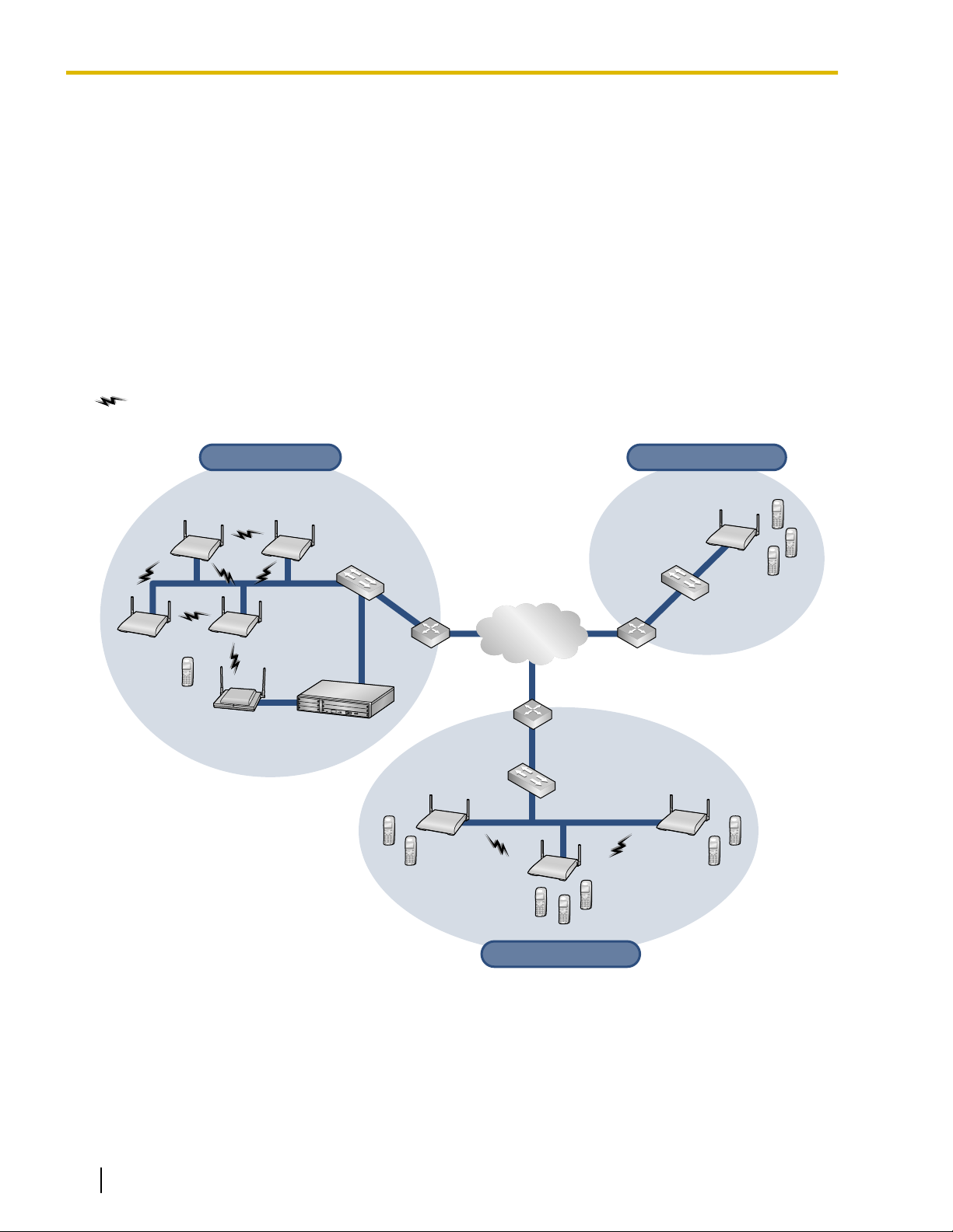
The IP Cell Station Unit (IP-CS) can be connected to a PBX via a LAN. The IP-CS supports existing DECT 6.0
Portable Stations (PSs) with the same features as using a traditional CS. The IP-CS allows for easy and
cost-saving installation using an existing IP network infrastructure.
The IP-CS provides the following:
– Wireless systems using a converged voice and data network infrastructure.
– Wireless branch offices and wireless solutions by long distance installation on larger premises.
– Reliable wireless communication using DECT 6.0 technology over an IP network.
The following is an example of IP-CS installation using an IP network.
: Handover is working.
6 Quick Installation Guide Document Version 2009-06
Switching HubRouter IP-CSRouter
IP Network
Switching Hub
IP-CS IP-CS
IP-CS IP-CS
PBX
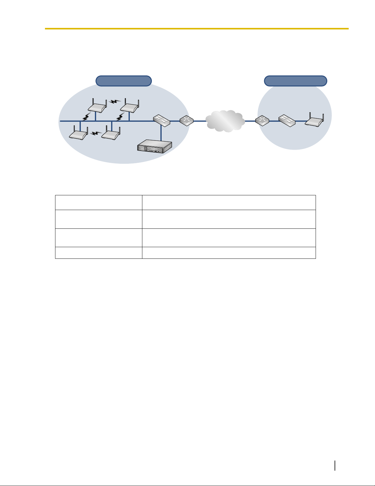
Remote Office
Remote Office
Headquarters
Headquarters
Air Synchronization is required Air Synchronization is not required
1 Overview
Air Synchronization
It is necessary to establish synchronization for stable operation and handover between IP-CSs and other CSs.
As a method of synchronization, air synchronization is used.
CSs are classified into one of the following three classifications for implementing air synchronization:
CS Class
Master CS1 (synchronization
Generates clock signal.
Description
source clock)
Master CS2 (backup for
Master CS1)
Receives clock signal from Master CS1 (can also generate
clock signal if Master CS1 malfunctions).
Slave CS Receives clock signal from other CSs.
Document Version 2009-06 Quick Installation Guide 7
Switching Hub IP-CS
PBX
Switching Hub
PBX
IP-CS IP-CS
IP-CS IP-CS
Switching Hub
PBX
IP-CS IP-CS
IP-CS IP-CS
Traditional CS
Traditional CS
1 Overview
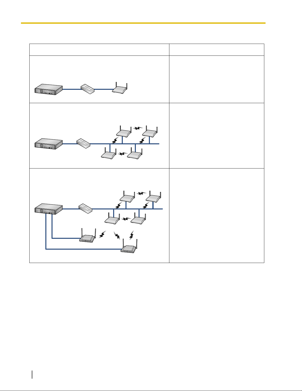
System Connection Examples
Connection Example Characteristics
Using one IP-CS only
When installing only one IP-CS at a remote office.
Using multiple IP-CSs
When creating a new wireless network.
Using multiple IP-CSs and traditional CSs
When adding IP-CSs to an existing wireless network.
• No need to conduct site planning and
site survey for air synchronization.
• Need to conduct site planning and site
survey for air synchronization.
• Need to conduct site planning and site
survey for air synchronization.
• Need to update the software version
of traditional CSs as follows:
– KX-T0158: version 4.015 or later
– KX-T0151: version 4.002 or later
– KX-TDA0156: version 4.002 or
later
8 Quick Installation Guide Document Version 2009-06
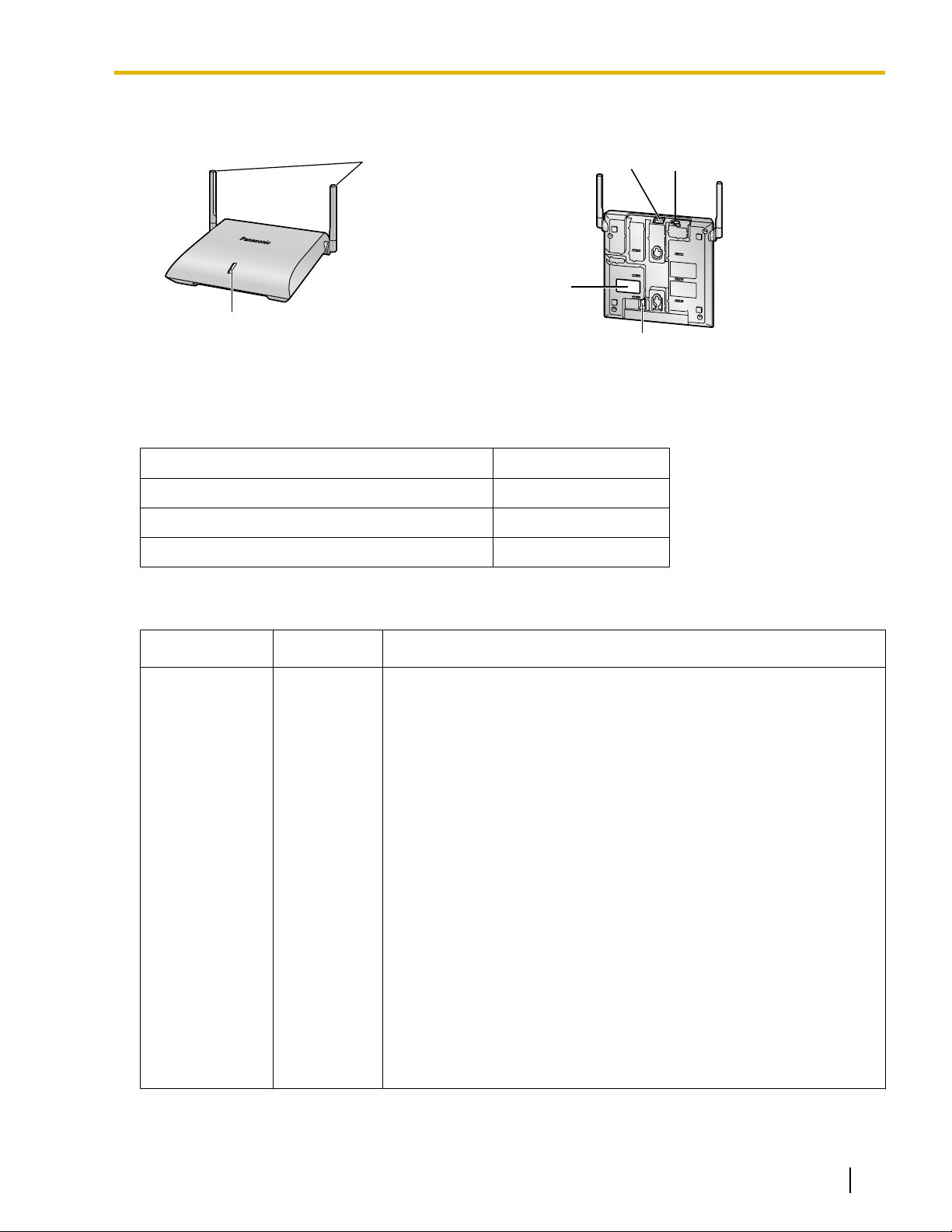
Names and Locations
LED
Antennas
CS ID Number
(ID: xxxxxxxxxx)
DIP Switch
RJ45 Modular
DC Jack
Unpacking
Unpack the box and check the items below:
Cell Station 1
Wall Mounting Plate 1
1 Overview
Screws 2
Washers 2
LED Indications
Indication
STATUS Green/Red/
Color Description
CS status indication
Amber
• OFF: Power Off/CS Software downloading
• Green ON: Stand-by (no active calls)
• Slow Green Flashing: Talk (active calls)
• Moderate Green Flashing: Busy
• Red ON: Fault
• Slow Red Flashing: Out of Service/Starting up (data link
establishment ® air synchronization)
• Moderate Red Flashing: Starting up (power on ® data link
establishment)
• Amber ON: Stand-by (unstable synchronization [no active calls])
• Slow Amber Flashing: Talk (unstable synchronization [active calls])
• Moderate Amber Flashing: Busy
CS status indication during the site survey
• Red ON: The CS is connected to an AC adaptor/PoE device.
• Red Flashing (60 times per minute): The CS is connected to the
PBX.
CS status indication while restarting the CS
• Red Flashing (120 times per minute): The CS is restarting.
*1
*1
(unstable synchronization)
*1
All 8 channels are occupied.
Document Version 2009-06 Quick Installation Guide 9
1 Overview
Maximum Number of Calls
Cell Stations (CSs) determine the area covered by the wireless system. The number of calls that can be made
simultaneously through each CS varies depending on the model, as follows:
Cell Station Maximum Calls Compatible Portable Station
KX-NCP0158 8
• KX-TD7685
• KX-TD7695
• KX-TD7696
Note
For more details about the Portable Station (PS), refer to the Operating Instructions of the PS.
Maximum Number of CSs Supported by PBX
Notice
The CSs are for connection to specified Panasonic PBXs only.
The following number of CSs can be supported by each PBX.
PBX
KX-NCP500 LAN 8
KX-NCP1000 LAN 8
Connected via
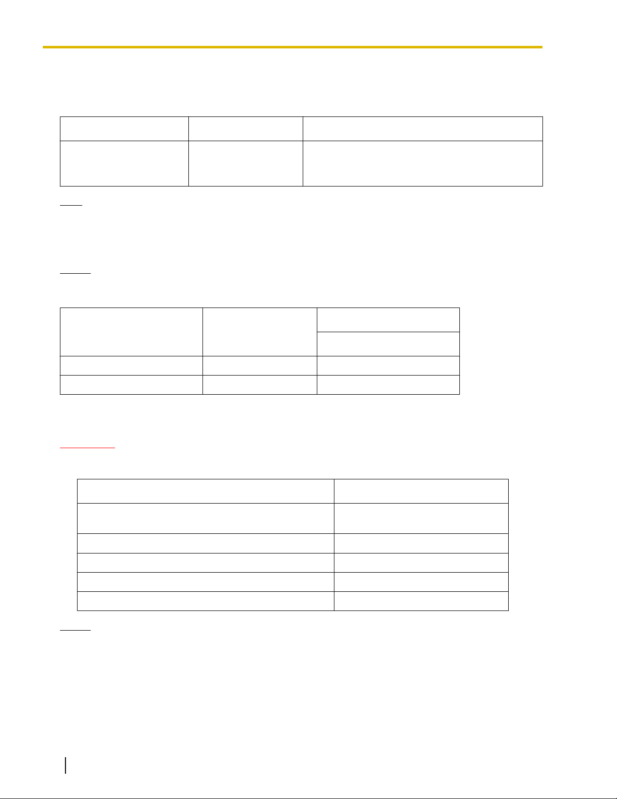
Required Distances between Equipment
Maximum Number
KX-NCP0158
CAUTION
Maintain the distances listed below between equipment in order to prevent noise, interference or the
disconnection of a conversation. (The distance may vary depending on the environment.)
Equipment
CS and office equipment such as a computer, telex, fax
machine, etc.
CS and PS More than 1 m (3 ft 3 in)
Each CS More than 3 m (10 ft)
Each PS More than 0.5 m (1 ft 8 in)
PBX and CS More than 2 m (6 ft 7 in)
Notice
If multiple CSs cover the same area, the phone connection may become noisy or the number of possible
simultaneous calls with PSs may decrease due to interference between the CSs. For details, refer
to "5 Site Survey Using the KX-TD7685/KX-TD7695/KX-TD7696—Testing the Radio Signal Strength".
The required distance between CSs may vary depending on the environment of the installation site and
conditions in which the wireless system is used. Conduct a site survey to determine the appropriate
distance.
More than 2 m (6 ft 7 in)
Distance
10 Quick Installation Guide Document Version 2009-06
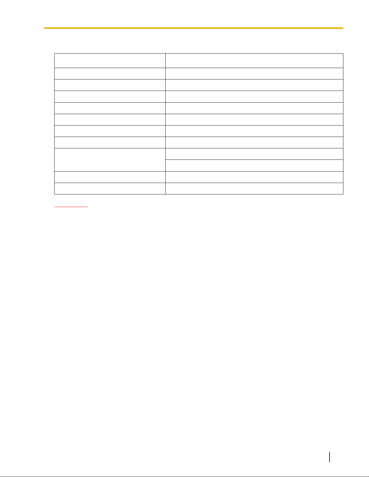
RF Specification
Item Description
Radio Access Method MultiCarrier TDMA-TDD
Frequency Band 1920 MHz to 1930 MHz
Number of Carriers 5
Carrier Spacing 1728 kHz
Bit Rate 1152 kbps
Carrier Multiplex TDMA, 24 (Tx12, Rx12) slots per frame
Frame Length 10 ms
Modulation Scheme GFSK
Roll-off factor=0.5 50 % roll-off in the transmitter
Data Coding for Modulator Differential Coding
Voice Codec 32 kbps ADPCM (CCITT G.726)
1 Overview
CAUTION
• The CS should be kept free of dust, moisture, high temperature (more than 40 °C [104 °F]), low
temperature (less than 0 °C [32 °F]), and vibration, and should not be exposed to direct sunlight.
• The CS should not be placed outdoors (use indoors).
• The CS should not be placed near high-voltage equipment.
• The CS should not be placed on a metal object.
Document Version 2009-06 Quick Installation Guide 11
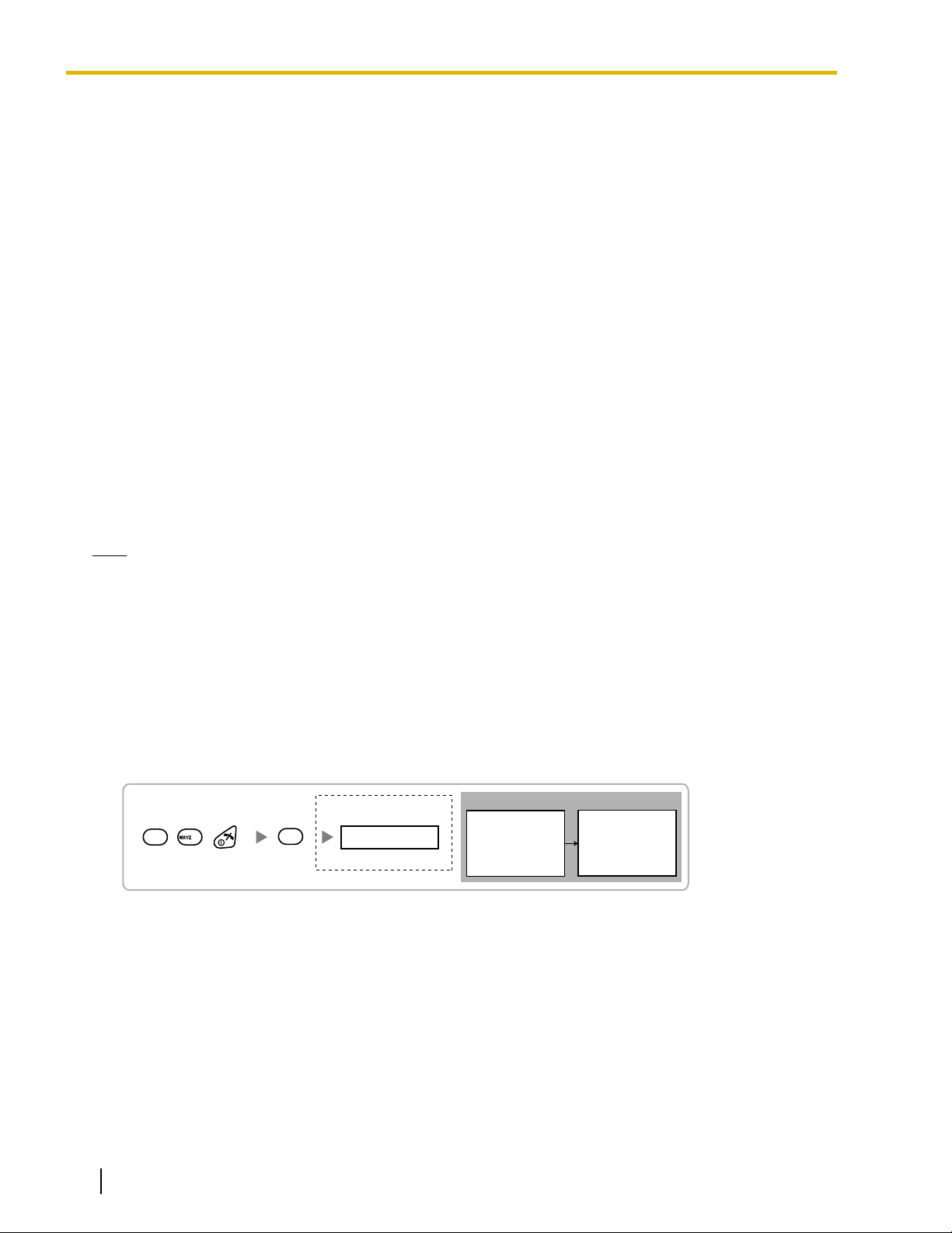
Display example:
RADIO STRENGTH
<<< MEASURING >>>
RADIO STRENGTH
CH0 SLOT:06 SYNC
L:12 0000/0100
CS-ID:9005301234
Press 1, 9, and POWER
for more than 2 seconds.
1
9
9
0
0 to 4
Channel No.
To survey
specific channel
2 Procedure Overview
2 Procedure Overview
When connecting the wireless system, use extreme care in conducting the site survey. Site surveys can be
conducted using the KX-TD7685/KX-TD7695/KX-TD7696 PS. An incorrectly performed site survey can result
in poor service area, frequent noise, disconnection of calls, and synchronization failure for CSs.
1. Investigate the installation site
Refer to "3 Site Planning".
a. Obtain a map of the CS installation site.
b. Identify the service area required by the user on the map.
c. Plan the location of each CS, taking account of distance, building materials, etc.
2. Prepare for site survey
Refer to "4 Before Site Survey".
a. Check and assign the CS ID number to the PS.
b. Assign a channel number to each CS by setting the DIP switches on the back of the CS.
c. Supply electricity to each CS using an AC adaptor or by connecting them to a PoE hub/PoE adaptor.
d. Install each CS temporarily as planned.
Note
• Install at least 2 m (6 ft 7 in) above the floor.
• Place the antennas so that they are pointing in directions that are 90 degrees apart (for antenna
diversity).
3. Conduct the site survey
Refer to "5 Site Survey Using the KX-TD7685/KX-TD7695/KX-TD7696".
a. Test the radio signal strength using the PS.
Confirm that the radio signal strength level is "12" near the CS.
Using the KX-TD7685/KX-TD7695/KX-TD7696
b. By walking away from the CS with the PS, check the radio signal strength. The radio signal strength
weakens as you walk away from the CS.
c. Map the CS coverage area at radio signal strength levels "3" and "5".
d. Plan the location of the CS so that its clock signal source is within range of the CS where the radio signal
strength level is "5".
e. Make sure that the radio signal strength level is greater than "3" at any location within the service area
required by the user.
4. Finish the site survey
Refer to "6 After Site Survey".
12 Quick Installation Guide Document Version 2009-06

2 Procedure Overview
a. Turn off the PS.
b. Stop supplying power, and return all DIP switches of each CS to the OFF position.
5. Connect the CS to the PBX
Refer to "7 Connecting IP Cell Stations".
a. Assign IP address information to the CS using the IP Terminal Maintenance Console.
b. Connect the CS to the PBX over a LAN.
6. Register the CS to the PBX
Refer to "8 Registering IP Cell Stations".
a. Register the CS to the PBX using the Maintenance Console.
b. Assign the Master CSs and set the synchronizing CS search order using the Maintenance Console.
7. Confirm the status of Air Synchronization for the CS
Refer to "9 Confirming the Status of Air Synchronization for IP Cell Stations".
a. Check the status of air synchronization for the CS using the Maintenance Console.
b. If the monitoring results are not satisfactory, relocate the CS or change the CS that it is currently
synchronized with to another CS using the Maintenance Console.
8. Connect the PS to the PBX and test the operation
Refer to "10 Registering Portable Stations".
a. Register the PSs to the PBX.
b. Walk around the service area while having a conversation using a registered PS. If noise is frequent or
conversations disconnect, relocate the CSs or install an additional CS.
9. Mount the CS on the wall
Refer to "11 Wall Mounting".
a. If there are no problems in testing, mount the CS on the wall.
Document Version 2009-06 Quick Installation Guide 13
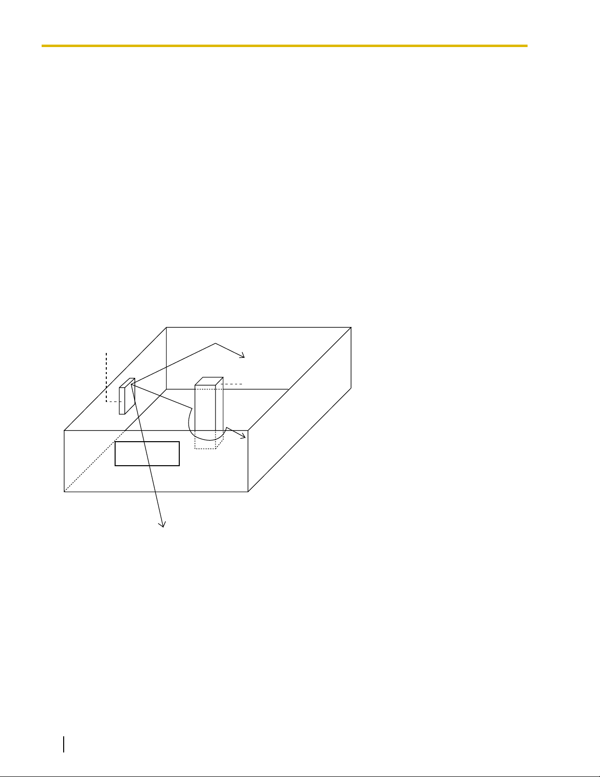
CS
Column
3. Penetration
2. Diffraction
1. Reflection
3 Site Planning
3 Site Planning
Choosing the best site for the CS requires careful planning and testing of essential areas. The best location
may not always be convenient for installation. Read the following information before installing the unit.
Understanding Radio Waves
Characteristics of Radio Waves
The transmission of radio waves and the CS coverage area depend on the structure and materials of the
building.
Office equipment, such as computers and fax machines, can interfere with radio waves. Such equipment may
create noise or interfere with the performance of the PS.
The illustration below shows the special transmitting patterns of radio waves.
1. Radio waves are reflected by objects made of materials such as metal.
2. Radio waves are diffracted by objects such as metallic columns.
3. Radio waves penetrate objects made of materials such as glass.
Relationships Between Radio Waves and Building Structure and Materials
• The CS coverage area is affected more by the building materials and their thickness than the number of
obstacles.
• Radio waves tend to be reflected or diffracted by conductive objects and rarely penetrate them.
• Radio waves tend to penetrate insulated objects and are rarely reflected by them.
• Radio waves penetrate thin objects more than thick objects.
• The table below shows the transmission tendency of radio waves when they reach objects made from
various materials.
14 Quick Installation Guide Document Version 2009-06
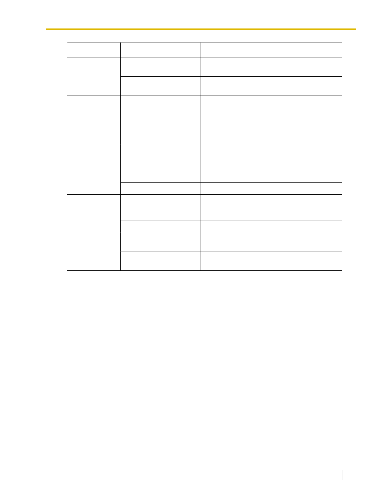
Object Material Transmission Tendency
Wall Concrete The thicker they are, the less radio waves
penetrate them.
Ferroconcrete Radio waves can penetrate them, but the more
iron there is, the more radio waves are reflected.
Window Glass Radio waves usually penetrate them.
Glass with wire net Radio waves can penetrate them, but tend to be
reflected.
3 Site Planning
Glass covered with
heatresistant film
Radio waves are weakened considerably when
they penetrate windows.
Floor Ferroconcrete Radio waves can penetrate them, but the more
iron there is, the more radio waves are reflected.
Partition Steel Radio waves are reflected and rarely penetrate
them.
Plywood, Glass Radio waves usually penetrate them.
Column Ferroconcrete Radio waves can penetrate them, but the more
iron there is, the more radio waves tend to be
reflected or diffracted.
Metal Radio waves tend to be reflected or diffracted.
Cabinet Steel Radio waves are usually reflected or diffracted,
and rarely penetrate them.
Wood Radio waves can penetrate them, but they are
weakened.
Document Version 2009-06 Quick Installation Guide 15
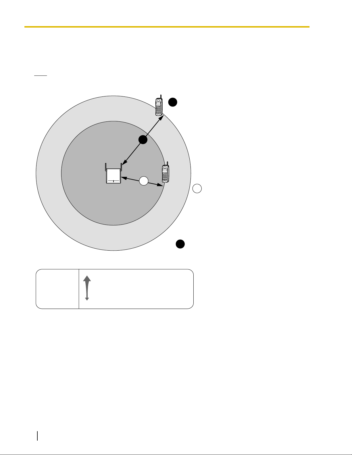
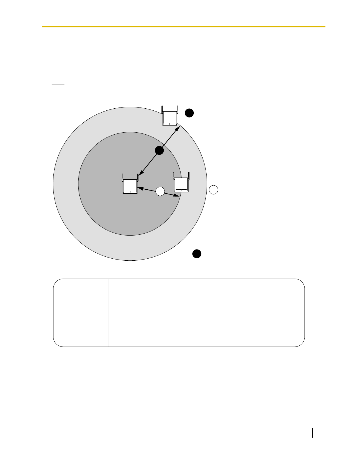
A
B
C
A
B
Gray Zone:
Conversation will be
intermittent
Out of Service:
Cannot make/receive calls.
Good Coverage Area
Radio signal strength
level is greater than "8".
(About 30 m to 40 m
[98 ft to 131 ft])
Good sound quality
can be maintained.
Coverage Area
Radio signal strength level is
greater than "3".
(About 50 m to 60 m
[164 ft to 197 ft])
Radio Signal Strength Levels
Better
Good
May receive noise
Receives noise easily or disconnects
Out of range
Level: 11 to 12
Level: 08 to 10
Level: 03 to 07
Level: 01 to 02
Level: 00
3 Site Planning
CS Coverage Area for Establishing Conversation Using PSs
The example below shows the size of the area where one CS can cover PSs, if it is installed in an area with
no obstacles.
Note
Radio signal strength levels are measured during the site survey (refer to "5 Site Survey Using the
KX-TD7685/KX-TD7695/KX-TD7696").
16 Quick Installation Guide Document Version 2009-06
A
B
C
A
B
Gray Zone:
Conversation will be
intermittent
Out of Service:
Cannot be synchronized.
Good Coverage Area
Radio signal strength level is
between "5" (about 40 m to 50 m
[131 ft to 164 ft]) and "11"
(about 20 m to 30 m [65 ft to 98 ft]).
Good synchronization quality
can be maintained.
Coverage Area
Radio signal strength level is
greater than "3".
(About 50 m to 60 m [164 ft to 197 ft])
Radio Signal Strength Levels
Level: 12 or higher May be reset due to synchronization failure of CSs
Level: 05 to 11 Good
Level: 03 to 04 Air synchronization is established. However, it is necessary to monitor
the status of synchronization using the Maintenance Console.
This is necessary because IP-CSs may be reset due to synchronization
failure if the radio signal strength fluctuates depending on changes in
the installation environment such as opening/closing doors.
Level: 00 to 02 May be reset due to synchronization failure of CSs
3 Site Planning
Implementing Air Synchronization
CS Coverage Area for Air Synchronization between CSs
The example below shows the size of the area where one CS can synchronize with other CSs, if it is installed
in an area with no obstacles.
Note
Radio signal strength levels are measured during the site survey (refer to "5 Site Survey Using the
KX-TD7685/KX-TD7695/KX-TD7696").
Document Version 2009-06 Quick Installation Guide 17
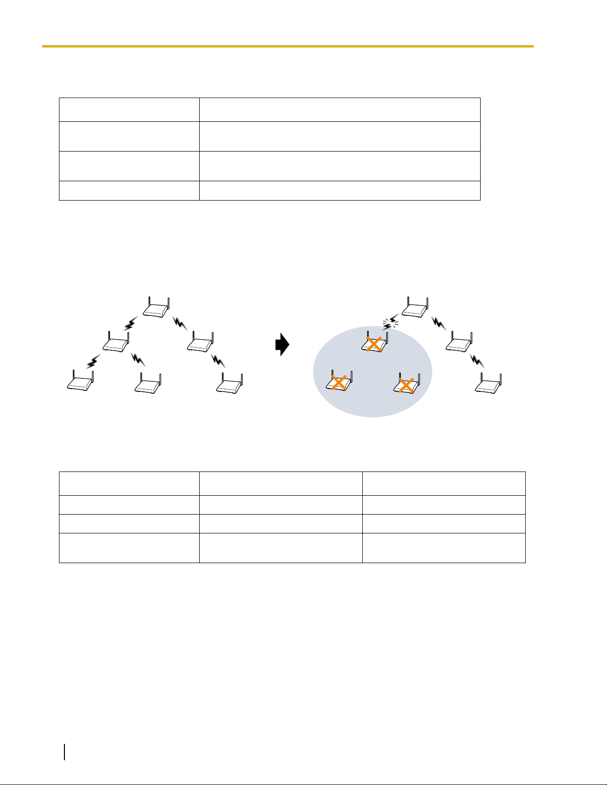
Master CS1
(Master Clock Signal)
Master CS2
Slave CSs Slave CS
Master CS1
(Master Clock Signal)
Master CS2
Slave CSs Slave CS
Radio Link Loss
CSs stop working
3 Site Planning
CS Classifications
CSs are assigned to any one of the following three classifications for implementing air synchronization:
CS Class Description
Master CS1 (synchronization
Generates clock signal.
source clock)
Master CS2 (backup for
Master CS1)
Receives clock signal from Master CS1 (can also generate
clock signal if Master CS1 malfunctions).
Slave CS Receives clock signal from other CSs.
Synchronization Hierarchy
Air synchronization has a hierarchical structure with a Master CS1 at the top. Therefore, it is necessary to
conduct the site survey with extreme care to ensure stable synchronization since one disruption of the radio
link could loss of service to a wide area.
Search Order (Primary/Secondary)
The search order used for synchronizing CSs must be set. If the CS cannot synchronize with the Primary CS
for some reason, it will try to synchronize with the Secondary CS.
CS Class
Primary CS Secondary CS
Master CS1 None None
Master CS2 Master CS1 None
Slave CS Master CS1, Master CS2, or SlaveCSMaster CS1, Master CS2, Slave
CS, or None
For example, if synchronization is completely lost by malfunction of the Master CS etc., handover will not work
and ongoing calls will be disconnected after a while. In addition, new calls cannot be made or received.
Therefore, it is recommended to not only assign the Primary CS but also the Secondary CS as an alternative
source for synchronizing CSs.
Conditions for Configuring the Air Synchronization
• Master CS2 must be within range of Master CS1.
• It is recommended that Master CSs be placed in the middle of the installation site.
• Both the Primary CS and Secondary CS should be assigned Slave CSs.
• All traditional CSs are automatically assigned and fixed as Master CS1.
• When using IP-CSs and traditional CSs in the same area, make sure that you do not create a Master CS2.
18 Quick Installation Guide Document Version 2009-06

3 Site Planning
• It is recommended that the number of levels in the synchronization hierarchy is minimized for stable air
synchronization. The maximum number of levels is 4.
Notice
A repeater can only receive the clock signal from one source CS (Secondary CS cannot be set). Therefore,
when you extend the coverage area using repeaters, minimize the number of IP-CSs that are synchronized
with the repeater.
Note
For your convenience, IP-CSs are automatically classified according to the order of their registration to the
PBX. Therefore, it is recommended to register the CS that you want to assign to Master CS1 first. For
example, when using IP-CSs and traditional CSs in the same area, connect the traditional CSs to the PBX
first.
Document Version 2009-06 Quick Installation Guide 19
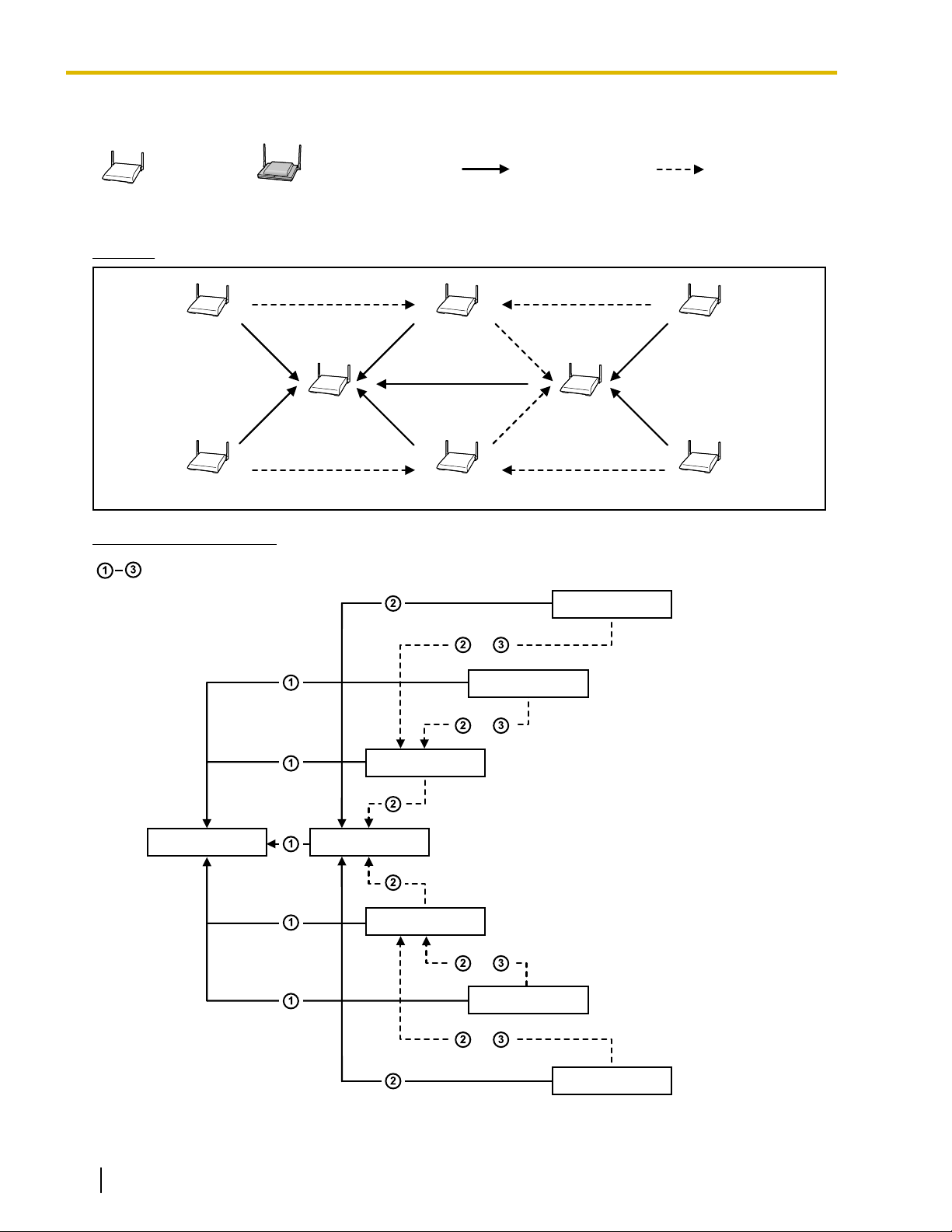
Traditional CS
IP-CS
Primary CS Secondary CS
Slave CS3
Slave CS4
Slave CS5
Slave CS6
Slave CS1
Master CS1 Master CS2
Slave CS2
Master CS1 Master CS2
Slave CS1
Slave CS2
Slave CS4
Slave CS3
Slave CS5
Slave CS6
oror
oror
oror
oror
: Hierarchy levels (e.g., Master CS2: 1st hierarchy level)
3 Site Planning
Recommended Configuration
[Configuration Example 1]
Diagram
Air Synchronization Tree
20 Quick Installation Guide Document Version 2009-06
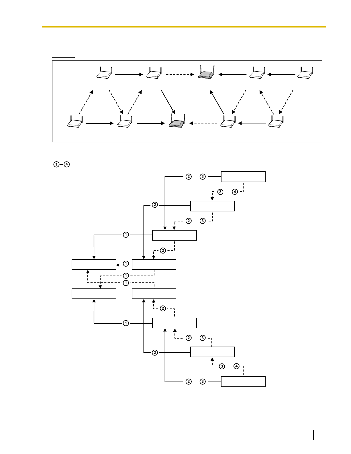
[Configuration Example 2]
Master CS1(B)Slave CS5 Slave CS1 Slave CS4 Slave CS8
Master CS1(A)Slave CS7 Slave CS3 Slave CS2 Slave CS6
Master CS1(A) Slave CS1
Master CS1(B) Slave CS2
Slave CS3
Slave CS4
Slave CS6
Slave CS5
Slave CS7
Slave CS8
oror
oror
oror
: Hierarchy levels (e.g., Slave CS1: 1st hierarchy level)
oror
oror
oror
Diagram
Air Synchronization Tree
3 Site Planning
Document Version 2009-06 Quick Installation Guide 21
 Loading...