

WV-SPN531
Standard accessories
IMPORTANT:
Connect/disconnect the audio cables and turn on the power of the camera after turning ●
off the power of the audio output devices. Otherwise, loud noise may be heard from
the speaker.
Make sure that the stereo mini plug is connected to this cable. When a monaural mini ●
plug is connected, audio may not be heard.
When connecting a monaural speaker with amplifier, use a locally procured conversion
cable (mono-stereo).
IMPORTANT:
Do not connect 2 wires or more directly to a terminal. When it is necessary to con- ●
nect 2 or more wires, use a splitter.
Off, input, and output of the external I/O terminal 2 and 3 can be switched by con- ●
figuring the setting. Refer to the Operating Instructions on the provided CD-ROM
for further information about the EXT I/O terminal 2 and 3 (ALARM IN2, 3) settings
(“Off”, “Alarm input”, “Alarm output” or “AUX output”).
Install external devices so that they do not exceed the rating of the network camera. ●
When using the EXT I/O terminals as the output terminals, ensure they do not ●
cause signal collision with external signals.
IMPORTANT:
The adjustment monitor is used for checking the adjustment of the angular field of ●
view when installing the camera or when servicing. It is not provided for recording/
monitoring use.
Depending on the monitor, some characters (camera title, preset ID, etc.) may not ●
be displayed on the screen.
Use a switching hub or a router which is compliant with 10BASE-T/100BASE-TX. ●
If a PoE hub is not used, each network camera must be connected to a 12 V DC ●
power supply.
When using 12 V DC, power supply from a PoE hub or router is not required. ●
PoE device (hub)
PC
LAN cable (category 5
or better, straight)
Adjustment monitor
Adjustment monitor
LAN cable
(category 5 or better, straight)
LAN cable
(category 5 or better, straight)
Powered speaker
Microphone
Powered speaker
Microphone
Note:
Check whether the stripped part of the wire is not exposed and is securely connected. ●
IMPORTANT:
This is valid if the [Monitor out] is set to [Switch priority] ([Switch priority] is selected by ●
default).For details, refer to the Operating Instructions (included in the CD-ROM).
IMPORTANT:
When the camera is initialized, the settings including the network settings will be initial- ●
ized. Note that the CRT key (SSL encryption key) used for the HTTPS protocol will not
be initialized.
Before initializing the settings, it is recommended to write down the settings in advance. ●
Do not turn off the power of the camera during the process of initialization. Otherwise, it ●
may fail to initialize and may cause malfunction.
1 2 3 4
Panasonic System Networks Co., Ltd. 2014
-
+
IMPORTANT:
The 12 V DC power supply shall be insulated from the commercial AC power. ●
Be sure to use the power cord plug provided with this product. ●
Be sure to fully insert the power cord plug into the 12 V DC power supply terminal. ●
Otherwise, it may damage the camera or cause malfunction.
When installing the camera, make sure that excessive force is not applied to the ●
power cable.
Be sure to use an AC adaptor compliant with the Specifications (written in the indi- ●
cation label on the bottom side of this unit) regarding power source and power consumption.
Caution:
A READILY ACCESSIBLE DISCONNECT DEVICE SHALL BE INCORPORATED ●
TO THE EQUIPMENT POWERED BY 12 V DC POWER SUPPLY.
ONLY CONNECT 12 V DC CLASS 2 POWER SUPPLY (UL 1310/CSA 223) or ●
LIMITED POWER SOURCE (IEC/EN/UL/CSA 60950-1).
Note:
Check whether the stripped part of the wire is not exposed and is securely con- ●
nected.
When connecting an external power supply to the camera, use the AWG 16 to ●
AWG 24 single-wired or stranded wired cables.
IMPORTANT:
Use all 4 pairs (8 pins) of the LAN cable. ●
The maximum cable length is 100 m {328 feet}. ●
Make sure that the PoE device in use is compliant with IEEE802.3af standard. ●
When connecting both the 12 V DC power supply and the PoE device for power ●
supply, 12 V DC will be used for power supply.*
If a 12 V DC power supply and a PoE hub or router are used at the same time, *
network connections may not be possible. In this case, disable the PoE settings.
Refer to the operating instructions of the PoE hub or router in use.
Depending on the PoE device used, if you disconnect 12 V DC while 12 V DC *
power supply and a PoE hub or router are used at the same time, the power supply
may stop, causing the camera to restart.
When the LAN cable is disconnected once, reconnect the cable after around ●
2 seconds. When the cable is quickly reconnected, the power may not be supplied
from the PoE device.
Note:
Use audio cables that do not exceed the sizes described ●
in the illustrations.
ø9 mm
{11/32 inches}
Example of audio cable
connector
Making connections
Connect the power cable
Installation Guide
Included Installation Instructions
Network Camera
Model No. WV-SPN531
Please purchase the recommended lens separately.
This manual describes the installation procedures, network camera installation, cable connections, ●
and the angle of view adjustment.
Before reading this manual, be sure to read the Important Information. ●
Important Information ...............................1 pc.
Installation Guide (this document) ............1 set
Warranty card ...........................................1 set
*1 The CD-ROM contains the operating instructions and different kinds of tool software programs.
*2 This label may be required for network management. The network administrator shall retain the
code label.
The following parts are used during installation procedures.
A Tripod mount base ............................... 1 pc.
C
Safety wire lug
E Safety wire ........................................... 1 pc.
F Washer ................................................. 1 pc.
G Spring washer ...................................... 1 pc.
B
Slide cover
...................................... 1 pc.
SD ON/OFF button
Auto back focus button (ABF)
CD-ROM*
Code label*
B Power cord plug ................................... 1 pc.
D Wire lug fixing screws
SD memory card slot
1
................................................ 1 pc.
2
.............................................. 1 pc.
(M2.5 x 8 mm {5/16 inches}) ............. 2 pcs.
(of them, 1 for spare)
Turn off each system’s power supply before making a connection. Before making connections,
prepare the required peripheral devices and cables.
Connect a LAN cable (category 5 or better, straight)
Connect a LAN cable (category 5 or better, straight) to the network connector.
Connect the output cable of the DC power supply to the power cord plug (B: accessory).
q Loosen the screw of the power cord plug, strip 3 mm to 7 mm {1/8 inches to 9/32 inches}
from the end of the wire, twist the stripped part of the wire sufficiently to avoid short circuit,
and then connect the output cable to the power cord plug.
w Tighten the screw of the power cord plug. (Recommended tightening torque: 0.34 N·m
{0.25 lbf·ft})
For U.S. and Canada:
Panasonic System Communications
Company of North America,
Unit of Panasonic Corporation
of North America
www.panasonic.com/business/
For customer support, call 1.800.528.6747
Two Riverfront Plaza, Newark, NJ 07102-5490
Panasonic Canada Inc.
5770 Ambler Drive, Mississauga,
Ontario, L4W 2T3 Canada
(905)624-5010
www.panasonic.ca
For Europe and other countries:
Panasonic Corporation
http://panasonic.net
Panasonic System Networks Co., Ltd.
Fukuoka, Japan
Authorised Representative in EU:
Panasonic Testing Centre
Panasonic Marketing Europe GmbH
Winsbergring 15, 22525 Hamburg, Germany
PGQX1761ZA Cs1014-0 Printed in China
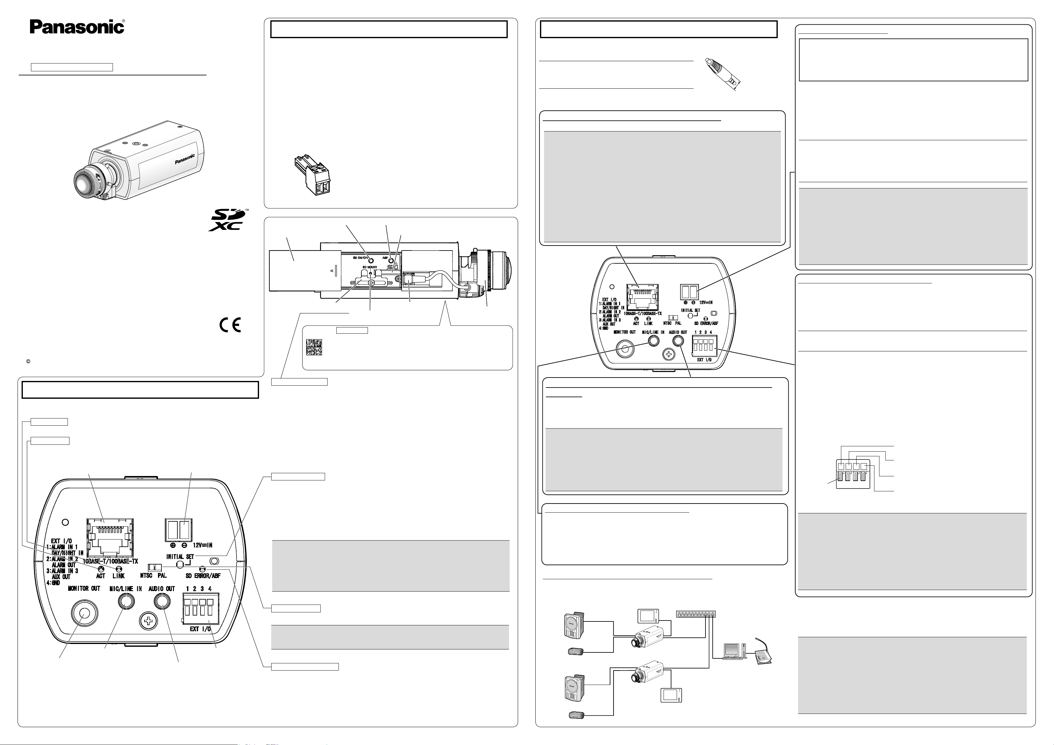
Major operating controls
The component names of the camera are as follows. Refer to the illustration when installing or
adjusting the camera.
ACT indicator
When data is being sent via the network camera Blinks green (accessing) ●
LINK indicator
When the camera is able to communicate with Lights orange ●
the connected device
Network connector RJ45
*1
12 V DC power supply terminal*1
Clamp for SD memory card
SD MOUNT indicator
Data Matrix Bottom side : To our website
Depending on the scanning application used, the Data Matrix may not be
able to be read correctly. In this case, access the site by directly entering
the following URL.
http://security.panasonic.com/pss/security/support/qr_sp_select.html
SD MOUNT indicator
When an SD memory card ●
be recognized Lights off
When data can be saved after the SD memory card is Lights off → Lights green ●
inserted and the SD ON/OFF button is pressed
When data can be saved to the SD memory card Lights green ●
When the SD memory card is removed after holding down ●
the SD ON/OFF button for about 2 seconds
When data cannot be saved to the SD memory card because
● Lights off
an abnormality was detected or the SD memory card is
configured not to be used
INITIAL SET button
How to initialize the camera ●
Follow the steps below to initialize the network camera.
q Turn off the power of the camera. When using a PoE hub, disconnect the LAN cable from
the camera. When using an external power supply, disconnect the power cord plug from the
12 V DC power supply terminal.
w Turn on the power of the camera while holding down the INITIAL SET button, and then
keep holding down the button for 5 seconds or more. About 2 minutes later, The camera will
start up and the settings including the network settings will be initialized.
*2
is inserted and could Lights off → Blinks green →
ALC lens connector
Lights green → Blinks green → Lights off
Lens (recommended)
Connect the alarm input/output cable
Connect the cables of external devices to the EXT I/O terminal plug.
When connecting an external device, remove 8 mm - 9 mm {5/16 inches - 11/32 inches} of
q
the outer jacket of the cable and twist the cable core to prevent the short circuit first.
Specification of cable (wire): AWG 20 - AWG 26, Single core, twisted
Push down the button of the desired terminal on the external I/O terminal plug with a ball-
w
point pen, and release the button when the cable of the external device is fully inserted
into the terminal hole.
<Ratings>
ALARM IN1(DAY/NIGHT IN), ALARM IN2, ALARM IN3 ●
Input specication : No-voltage make contact input (4 V - 5 V DC, internally pulled up)
OFF : Open or 4 V - 5 V DC
Connect an external speaker with amplier to the audio output
connector
Connect a stereo mini plug (ø3.5 mm) (Audio output is monaural.). Use an external powered speaker.
Output impedance : Approx. 600 Ω (unbalanced) ●
Recommended cable length : Less than 10 m {32.8 feet} ●
Output level : –20 dBV ●
ON : Make contact with GND (required drive current: 1 mA or more)
ALARM OUT, AUX OUT ●
Output specication
Open : 4 V - 5 V DC by internal pull-up
Close : Output voltage 1 V DC or less (maximum drive current: 50 mA)
* The default of EXT I/O terminals is “Off”.
button
External I/O terminal plug
: Open collector output (maximum applied voltage: 20 V DC)
ALARM IN1, DAY/NIGHT IN
(Alarm input terminal 1, DAY/NIGHT input terminal)
ALARM IN2, ALARM OUT
(Alarm input terminal 2, Alarm output terminal)
ALARM IN3, AUX OUT
(Alarm input terminal 3, AUX output terminal)
GND
Connect the microphone to MIC/LINE IN
Connect a monaural mini plug (ø3.5 mm).
Input impedance: Approx. 2 kΩ (unbalanced) ●
Recommended cable length: Less than 1 m {3.28 feet} (for microphone input) ●
Less than 10 m {32.8 feet} (for line input)
Recommended microphone: Plug-in power type (option) ●Supply voltage: 2.5 V ±0.5 V ●
Input level for the line input: Approx. –10 dBV ●
Recommended sensitivity of microphone: –48 dB ±3 dB (0 dB=1 V/Pa,1 kHz) ●
MONITOR OUT terminal
(factory shipment: NTSC monitor)
*1 The detailed specications on the right side in this page describe terminals
with markings.
*2 SDXC/SDHC/SD memory card is described as SD memory card.
Microphone/line input connector
*1
Audio output connector
EXT I/O terminals
When connecting to a network using a PoE hub
Before starting the installation, check the entire system configuration. The following illustration
gives a wiring example of how to connect the camera to the network via a PoE device (hub).
NTSC/PAL switch
The MONITOR OUT terminal output can be switched for the NTSC monitor/PAL monitor. ●
*1
*1
SD ERROR/ABF indicator
When ABF (Auto Back Focus) operation is being executed ●
When the set is being started Lights red ●
When an SD memory card is recognized normally Lights red → Lights off ●
When the ● SD memory card slot is not used or Lights red
an abnormality is detected in SD memory card
after the camera has started
Blinks red (Interval of 1 time/ second)
<Required cable>
LAN cable (category 5 or better, straight)
Use a LAN cable (category 5 or better, cross) when directly connecting the camera to a PC.
WV-SPN531
Installation
IMPORTANT:
The installation area shall be strong enough to hold the camera and camera mount ●
bracket.
The camera mount bracket (locally procured) shall be mounted on the foundation part of ●
the construction or a part with adequate strength.
Select screws according to the material of the ceiling that the camera will be mounted ●
to. In this case, wood screws and nails should not be used.
If a ceiling board such as plaster board is too weak to support the total weight, the ●
area shall be sufficiently reinforced.
1 3
2 4
Note:
● The most common use of a varifocal lens and a zoom lens
Note that the adjustment method is different depending on the type. For
further information, refer to the operating instructions for the lens to be
used.
When using 8x or 10x lens, adjust the back focus after positioning the
zoom ring at the "W" end and positioning the focus ring at a step short of
the "F" end.
When using 2x or 3x lens, adjust the back focus after positioning the
zoom ring at the "T" end and positioning the focus ring at a step short of
the "F" end.
● Depending on the lens to be used, if the zoom ring is fully rotated in the
"W" direction, the periphery may become dark. In such a case, rotate the
zoom ring in the "T" direction for readjustment.
● When images in the near-infrared light area change from the color mode
to the black & white mode, out-of-focus may be occurred according to the
nature of optical property. In this case, the focus can be corrected by
selecting "Auto" or "Preset" for "Adjusting method" on the setup menu
(The focus will not automatically be adjusted according to the illumination
level change once the focus is corrected.) Refer to the Operating
Instructions (included in the CD-ROM) for how to configure the "Adjusting
method" setting on the setup menu.
● When shooting the following subjects, it may have difficulty adjusting the
back focus position automatically.
In this case, adjust the back focus position manually from the setup
menu.
Refer to the Operating Instructions (included in the CD-ROM) for how to
perform the auto back focus function from the setup menu.
● Subj. moves frequently
● Subj. with large illuminance change
● Subj. with low illuminance
● Subj. through a window
● Subj. with less contrast such as white wall
● Subj. with heavy flicker
IMPORTANT:
Be sure to rotate and secure the camera ●
mount bracket. Rotating the camera places
a large burden on the camera mount bracket, and may cause damage.
Attach the safety wire in a position higher ●
than the camera and the mount bracket.
Attach the safety wire so that if the camera ●
were to become detached, it would not fall
on nearby people.
IMPORTANT:
Mount the bracket in a position higher than 2.7 m ● {8.86 feet} from the floor.
IMPORTANT:
Be sure to rotate and secure the camera mount bracket. Rotating the camera places ●
a large burden on the camera mount bracket, and may cause damage.
The safety wire shall be adjusted to remove slack. ●
The distance from the camera to the ceiling changes depending on the tilt angle of ●
the camera. Attach the safety wire in a position according to the tilt angle of the camera.
WV-SPN531
90°
360°
WV-SPN531
IMPORTANT:
After performing basic adjustments, make sure to press the auto back focus ●
button once to perform detailed adjustments.
WV-SPN531
Washer
(F: accessory)
Spring washer
(G: accessory)
Recommended screw M4
Minimum pull-out strength
24.5 N {5.5 lbf}
Safety wire
Ceiling
Safety wire
Recommended screw M4
Minimum pull-out strength 24.5 N {5.5 lbf}
Foundation part of
construction or part
with adequate strength
Wall
Washer (F: accessory)
Spring washer (G: accessory)
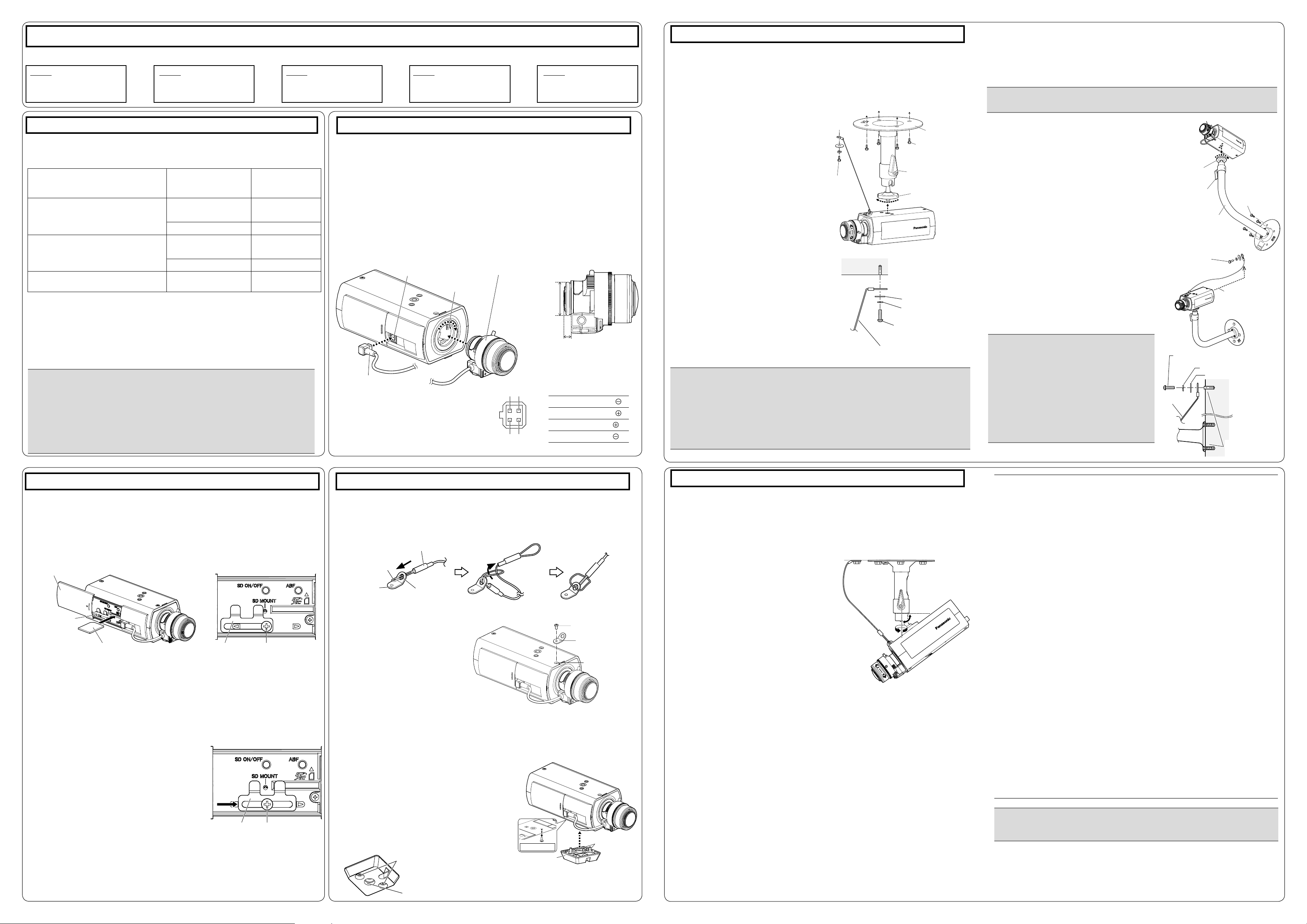
The installation tasks are explained using 5 steps.
Step1
Make sure all items are prepared
before beginning installation.
Step1 Preparations
To install the camera to a ceiling or wall, prepare the required mount bracket and the screws that
secure the bracket, or the anchor bolt for each installation method before starting the installation.
The following are requirement examples for the various installation methods.
Installation method Recommended screw
[1] For mounting on ceiling
(mount bracket: approx. 260 g
{0.57 lbs}, camera: 380 g {0.83 lbs},
lens: 70 g {0.15 lbs})
[2] For mounting on wall
(mount bracket: approx. 420 g
{0.93 lbs}, camera: 380 g {0.83 lbs},
lens: 70 g {0.15 lbs})
[3] When using the tripod mount
base (A: accessory)
*1 The number of required screws or anchor bolts varies depending on the specications
of the mount bracket (locally procured). Refer to the operating instructions of the mount
bracket (locally procured) for information about how to mount the mount bracket.
*2 Make sure that the screws or anchor bolts separately procured when locally procuring a
mount bracket for the ceiling or wall are capable of supporting the total weight (including
the moment force when mounting to a wall).
*3 Size of the bracket mounting hole: "1/4-20UNC camera tripod mounting hole (depth 9 mm
{11/32 inches})"
*1
*1
*3
Step2
Mount the lens to the camera.
M6 or M8 screws x 4
M4 x1(for the safety wire)
M6 or M8 screws x 4
M4 x1(for the safety wire)
— —
Minimum pull-out
strength
(per 1 pc.)
*1
562 N {126 lbf}
24.5 N {5.5 lbf}
*1
724 N {163 lbf}
24.5 N {5.5 lbf}
Step3
Insert/remove an SD memory
card.
*2
*2
Step4
Mount the camera.
Step5
Connect and adjust the
camera
Step2 Mount the lens to the camera
The lens section is not included with the camera. It is possible to mount a 1/3 type
video camera lens to the camera.It is recommended to use a recommended high-resolution lens especially when the illuminance level of the photographic subject is low
and the camera is used with the lens iris open. If a lens other than the recommended
lens is mounted and the camera is used at a resolution of 1280 x 720 or higher, the
camera cannot achieve full performance of high resolution.
Refer to our website (http://security.panasonic.com/pss/security/support/info.html) for
further information about the recommended lens.
* When using a lens made by other companies, use a lens that has a protruded por-
tion from the mount face of ø20 mm {25/32 inches} or less and a protruded portion
from the ange face of 4.5 mm {5/32 inches} or less.
ALC lens connector
Lens mounting hole
Lens (recommended)
Protruded portion
from mount face:
ø20 mm
{25/32 inches} or
less
Protruded portion from ange
face:
4.5 mm {5/32 inches} or less
Step4 Mount the camera (Continued)
For mounting on ceiling
[1] Mark the position of holes to be made for the ceiling mount bracket (locally procured) on
the attachment position of the ceiling, and make those holes for attachment.
Determine the hole diameter and hole depth according to the specications of the screws
or anchor bolts to be used.
[2] Secure the ceiling mount bracket (locally pro-
cured) using separately procured attachment
xing screws or anchors.
[3] Loosen the camera mount bracket xing
mechanism to freely move the camera mount
bracket.
Align the screw thread with the xing
screw hole of the camera, and rotate
the camera mount bracket to secure
the camera.
Recommended
screw M4
Minimum pull-out
strength
24.5 N {5.5 lbf}
Tighten the camera mount bracket xing mechanism and secure the camera
mount bracket.
* The tripod mount base (A: accessory) is not
used.
[4] Attach the safety wire to the foundation area
of the architecture or where sufcient strength
is assured. Prepare the xing screws ac-
cording to the material of the area where the
safety wire is to be installed.
Ceiling mount
bracket (example)
Attachment xing screws
M6 or M8 x4
(locally procured)
Camera mount bracket
xing mechanism
Camera mount bracket
For mounting on wall
[1] Mark the position of holes to be made for the wall mount bracket (locally procured) on the
attachment position of the wall, and make those holes for attachment.
Determine the hole diameter and hole depth according to the specications of the screws
or anchor bolts to be used.
[2] Secure the wall mount bracket (locally pro-
cured) using separately procured screws or
anchors.
[3] Loosen the camera mount bracket xing mecha-
nism to freely move the camera mount bracket.
Align the screw thread with the xing
screw hole of the camera, and rotate the
camera mount bracket to secure the camera. Tighten the camera mount bracket
xing mechanism and secure the camera
mount bracket.
* The tripod mount base (A: accessory) is not
used.
[4] Attach the safety wire to the foundation area of
the architecture or where sufcient strength is assured. Prepare the xing screws according to the
material of the area where the safety wire is to be
installed.
Camera mount
bracket
Camera mount brack-
et xing mechanism
Wall mount bracket
Attachment xing
screws M4 x1
(locally procured)
Attachment xing
screws
M6 or M8 x4
(locally procured)
(example)
Higher than the
camera and wall
mount bracket.
Step3 Insert/remove an SD memory card Step4 Mount the camera
When using an SD memory card, go through the following procedure before installing
the camera. When removing an SD memory card, reverse the procedure.
Refer to the Operating Instructions on the provided CD-ROM for further information
about the SD memory card settings.
[1] Open the slide cover on the side of the camera, loosen the screw (M3) of the clamp
for the SD memory card.
Slide cover
Clamp for SD
memory card
[2] Insert an SD memory card fully into the SD memory card slot until a click is heard.
SD memory card
* Label face downward
Clamp for SD
memory card
Screw of the clamp for
SD memory card
Insert the SD memory card with its label facing down. ●
[3] Slide the clamp for the SD memory card to the central position, and then tighten the
screw loosened in [1].
(Recommended tightening torque: 0.19 N·m {0.14 lbf·ft})
[4] Close the slide cover on the side of the camera.
● To remove the SD memory card, hold down
the SD ON/OFF button for about 2 seconds. When the flashing SD MOUNT indicator goes out, you can remove the SD
memory card.
● After the SD memory card has been
replaced, press the SD ON/OFF button,
and make sure the SD MOUNT indicator is
continually lit.
If you do not press the SD ON/OFF button ●
after replacing the SD memory card, the SD
MOUNT indicator is continually lit approximately 5 minutes later.
Clamp for SD
memory card
Screw of the clamp
for SD memory card
lens cable
q Remove the cover lm attached to the
lens mounting hole of the camera.
w Slowly rotate the lens clockwise to
mount the lens and connect the lens
cable to the ALC lens connector of the
camera.
ALC lens connector
Pin No.
1 Dump
2 Dump
3 Drive
4 Drive
Connect the safety wire
When securing the camera using a separately procured bracket, use the xing screw ●
(M4, locally procured), and the safety wire, washer, and spring washer (accessories).
[1] Engage the safety wire (E: accessory) with the wire engaging hole.
Safety wire (E: accessory)
Part A
Safety wire lug
(C: accessory)
q Pass part A through the wire en-
gaging hole
[2] Secure the safety wire lug
cessory) to the camera mount screw
hole with the wire lug xing screw
(D: accessory).
(Recommended tightening torque:
Wire engaging hole
(C: ac-
w Pass the other loop of the
wire through part A
After mounting
Wire lug xing screw
(D: accessory)
Safety wire lug
(C: accessory)
Fixing screw hole
0.39 N·m {0.29 lbf·ft})
When using the tripod
mount base
Use the tripod mount base ● (A: acces-
sory) when mounting the camera to
raise the camera mounting position.
Remove the screw from the camera's bottom ●
side. Please store the removed screw in a safe
location for when you choose to remove the
tripod mount base (A: accessory), as they will
not be needed from this point onwards.
[1] Secure the tripod mount base (A: acces-
sory) to the bottom side of the camera using
2 xing screws. (Recommended tightening
torque: 0.39 N·m {0.29 lbf·ft})
Size of the mounting hole: "1/4-20UNC
camera tripod mounting hole
(depth 9 mm
{11/32 inches})"
Fixing screws
1/4-20UNC camera
tripod mounting hole
(depth 9 mm {11/32 inches})
* The wire image mounted to the safety wire lug in
[1] of "Connect the safety wire" is not shown.
Bottom side
Tripod mount base
(A: accessory)
* The wire image mounted to the safety wire
lug in
[1] of "Connect the safety wire" is not
shown.
Fixing screws
Step5 Connect and adjust the camera
[1] Connecting wires
Connect the necessary cables/lead wires according to the procedure of "Making
connections". (When power is supplied by PoE, the camera is turned on when a
LAN cable is connected. Make sure to connect the LAN cable after turning off the
power of hub and router.)
[2] Adjusting the camera angle
Connect the adjustment monitor to the MONITOR OUT terminal of the camera with the RCA
pin cable (locally procured).
Loosen the
nism
camera mount bracket xing mecha-
on the camera mount bracket, and then
check the adjustment monitor to adjust the
camera angle.
When adjusting the camera angle, make sure
to loosen the camera mount bracket xing mech-
anism
on the camera mount bracket before
making adjustments.
If the camera angle is changed when the cam-
era mount bracket xing mechanism
is tightened,
excessive force is applied to the camera mount
bracket and camera, which may damage them.
After adjusting the camera angle, make sure to
tighten the camera mount bracket xing mecha-
nism
securely again.
[3] Adjusting the focus
q First, reset the back focus position by holding down the auto back focus button for
5 seconds or more when the power is on. (This operation can also be performed
on the setup menu. Refer to the Operating Instructions (included in the CDROM).)
w Manually adjust the angle of view and focus coarsely by adjusting the zoom and
focus of the lens to center a subject in the screen, and then press the auto back
focus button on the side of the camera (page 1) or perform the auto back focus
function from the setup menu.
Refer to the Operating Instructions (included in the CD-ROM) for how to perform
the auto back focus function from the setup menu.
* How to take a wide depth of field: When focus is desired on entire near or
distant subjects, select indoor scene mode, or adjust the focus to the midrange
position using manual focus adjustment.
After connecting the camera, refer to “Configure the settings of the cam- ●
era” (leaflet) and perform the camera settings.
 Loading...