

Panasonic WV-NS324 Operating Instructions
Model No. WV-NS324
Color CCTV Camera
Operating Instructions
Before attempting to connect or operate this product,
please read these instructions carefully and save this manual for future use.
FRANÇAIS
ENGLISH
-2-
WARNING: To prevent fire or electric shock hazard, do not expose this appliance to rain or moisture. The apparatus shall not be exposed
to dripping or splashing and that no objects filled with liquids, such as vases, shall be placed on the apparatus.
The lightning flash with arrowhead
symbol, within an equilateral triangle, is
intended to alert the user to the presence of uninsulated "dangerous voltage" within the product's enclosure that
may be of sufficient magnitude to constitute a risk of electric shock to persons.
The exclamation point within an equilateral triangle is intended to alert the
user to the presence of important operating and maintenance (servicing)
instructions in the literature accompanying the appliance.
The serial number of this product may be found on the top
of the unit.
You should note the serial number of this unit in the space
provided and retain this book as a permanent record of your
purchase to aid identification in the event of theft.
Model No. WV-NS324
Serial No.
Warning:
This equipment generates and uses radio frequency energy
and if not installed and used properly, i.e., in strict accordance with the instruction manual, may cause harmful
interference to radio communications. It has been tested
and found to comply with the limits for a Class A computing
device pursuant to Subpart J of Part 15 of FCC Rules,
which are designed to provide reasonable protection
against such interference when operated in a commercial
environment.
CAUTION:
TO REDUCE THE RISK OF ELECTRIC SHOCK, DO
NOT REMOVE COVER (OR BACK). NO USER SERVICEABLE PARTS INSIDE.
REFER SERVICING TO QUALIFIED SERVICE PERSONNEL.
CAUTION
RISK OF ELECTRIC SHOCK
DO NOT OPEN
SA 1965
SA 1966
For U.S.A
ENGLISH VERSION

-3-
IMPORTANT SAFETY INSTRUCTIONS
1) Read these instructions.
2) Keep these instructions.
3) Heed all warnings.
4) Follow all instructions.
5) Do not use this apparatus near water.
6) Clean only with dry cloth.
7) Do not block any ventilation openings. Install in accordance with the manufacturer's instructions.
8) Do not use near any heat sources such as radiators, heat registers, stoves, or other apparatus (including amplifiers) that produce heat.
9) Do not defeat the safety purpose of the polarized or grounding-type plug. A polarized plug has two blades with
one wider than the other. A grounding-type plug has two blades and a third grounding prong. The wide blade or
the third prong are provided for your safety. If the provided plug does not fit into your outlet, consult an electrician for replacement of the obsolete outlet.
10) Protect the power cord from being walked on or pinched particularly at plugs, convenience receptacles and the
points where they exit from the apparatus.
11) Only use attachments/accessories specified by the manufacturer.
12) Use only with the cart, stand, tripod, bracket, or table specified by the manufacturer, or sold with the apparatus.
When a cart is used, use caution when moving the cart/apparatus combination to avoid injury from tip-overs.
13) Unplug this apparatus during lightning storms or when unused for long periods of time.
14) Refer all servicing to qualified service personnel. Servicing is required when the apparatus has been damaged
in any way, such as power-supply cord or plug is damaged, liquid has been spilled or objects fallen into the
apparatus, the apparatus has been exposed to rain or moisture, does not operate normally, or has been
dropped.
ENGLISH
S3125A

-5-
CONTENTS
IMPORTANT SAFETY INSTRUCTIONS .......................................................................................................................... 3
PREFACE ....................................................................................................................................................................... 6
Features ......................................................................................................................................................................... 6
System Requirements .................................................................................................................................................... 6
Trademarks .................................................................................................................................................................... 6
Document Convention ................................................................................................................................................... 7
■ Camera Cleaning .................................................................................................................................................... 7
■ Preset Data Uploading or Downloading ................................................................................................................. 7
PRECAUTIONS .............................................................................................................................................................. 8
CONSTRUCTION ........................................................................................................................................................... 9
INSTALLATION .............................................................................................................................................................. 10
CONNECTIONS ............................................................................................................................................................. 13
SETUP WITH PC ............................................................................................................................................................ 16
■ Setup with the Provided "Panasonic IP Setup" Software ......................................................................................... 16
PREPARATIONS FOR THE PC ....................................................................................................................................... 17
■ Network Setup of Your PC ....................................................................................................................................... 17
■ Network Setup of the Camera ................................................................................................................................. 18
OPERATING THE CAMERA ........................................................................................................................................... 21
SETUP ............................................................................................................................................................................ 22
■ Setup Menu ............................................................................................................................................................. 22
SETTING PROCEDURES ............................................................................................................................................... 25
■ Menu Display .......................................................................................................................................................... 25
■ Presetting ................................................................................................................................................................ 25
■ Deleting Preset Positions ........................................................................................................................................ 28
■ Home Position Setting (HOME POSITION) ............................................................................................................. 29
■ Self-return Setting (SELF RETURN) ......................................................................................................................... 29
■ Auto Mode Selection (AUTO MODE) ...................................................................................................................... 29
■ Flip-A-Chip Setting .................................................................................................................................................. 31
■ Cleaning (CLEANING) ............................................................................................................................................ 31
■ Image Hold (IMAGE HOLD) .................................................................................................................................... 31
■ Camera Setting ....................................................................................................................................................... 32
INITIALIZING .................................................................................................................................................................. 40
Setting the Switches ....................................................................................................................................................... 40
Common procedures: .................................................................................................................................................... 40
TROUBLESHOOTING .................................................................................................................................................... 41
SPECIFICATIONS .......................................................................................................................................................... 42
PREVENTION OF BLOOMING AND SMEAR ................................................................................................................. 42
ACCESSORIES .............................................................................................................................................................. 43
OPTIONAL ACCESSORIES ............................................................................................................................................ 43
APPENDIX ...................................................................................................................................................................... 44

-6-
Features
• 10/100BASE-T terminal enables your PC to view
camera images via the network.
• Multiscreen function for simultaneous display of the
pictures of up to 4 cameras on the PC monitor
screen.
• Multishot function allows you to see surroundings
of the object with clicking one time.
• User authentication function is available.
• High quality picture of 768 x 494 pixels
• Minimum illumination of 1.0 lx
• Flip-a-chip allows 180 ° tilting to trace objects
passing under the camera.
• Auto pan
• BLC
• SENS UP X4 (MAX)
• MOTION DETECTOR
• 16 preset positions
•360 ° panning at a rotation speed of 100 °/s
• Sync selectable between internal, line-lock or VD2
• Automatic gain control circuit
•Image hold
• Digital noise reduction effect
System Requirements
Your personal computer must meet the following minimum requirements to view camera pictures or to set up
parameters.
Computer: PC/AT compatible
OS: One of the following should be installed.
Microsoft Windows98 Second Edition
Microsoft Windows2000 Professional Service
Pack2
Microsoft Windows Millennium Edition
Microsoft Windows XP
Microsoft Windows NT Workstation 4.0 Service
Pack6a
CPU: Pentium II (300 MHz) or faster
Memories: 128 MB or higher
Network Interface: 10/100Mbps Ethernet card
Applicable Network Protocols: TCP/IP,UDP/IP, HTTP,
FTP, SMTP, DNS, DDNS, DHCP, ARP, BOOTP,
NTP
Browser: One of the following should be installed.
Internet Explorer 5.01SP2, 5.5, 5.5SP2, 6.0
Netscape Communicator 4.73, 4.78
Caution under the circumstances of Netscape
Communicator except version 4.73 and 4.78
It may happen some of the functions work wrongly
when using the Netscape Communicator version 4.73
before, or upgraded version 4.73.
Then, take the following procedures on your PC:
1. Take notes all the setting status of Netscape
Communicator in advance.
2. Uninstall the old Netscape Communicator and
delete the holder named Netscape from your PC
once.
3. Install the applicable version of Netscape
Communicator to your PC.
4. Input the same setting status that item 1 to the
Netscape Communicator.
Trademarks
• Adobe, Adobe logos, and Acrobat are registered
trademarks of Adobe Systems Incorporated in the
U.S. and/ or other countries.
• Microsoft, Windows, Windows NT, and Windows XP
are registered trademarks of Microsoft Corporation
in the U.S. and/or other countries.
• Netscape, Netscape Navigator, Netscape ONE,
the Netscape N and Ship’s Wheel logos are registered trademarks of Netscape Communications
Corporation in the U.S. and other countries. Other
Netscape product names used in this document
are also trademarks of Netscape Communications
Corporation and may be registered outside the
U.S.
• Ethernet is a registered trademark of Xerox
Corporation.
• Other names of companies and products contained in these operating instructions may be
trademarks or registered trademarks of their
respective owners.
Panasonic introduces a newly developed dome camera with highly advanced CCTV technology for connection to
both conventional surveillance systems and digital networks. Color camera, zoom lens, pan and tilt mechanism are all
combined in a single compact unit.
This high-performance color CCTV camera is utilized as a video surveillance device.
It incorporates a Digital Signal Processor, pan-tilt mechanism, and x10 zoom lens in a compact enclosure.
A newly developed 1/4-inch CCD allows use under extremely low lighting conditions of 1.0 lx for color images.
Thanks to the use of the DSP it also assures clear display of pictures in which bright and dark objects coexist without
mutual interference. Setup menus allow the camera to fulfill surveillance tasks by such means as flip-a-chip and auto
pan.
PREF ACE

-7-
• Distributing, copying, disassembling, reverse compiling, reverse engineering, and also exporting in
violation of export laws of the software provided
with this product, is expressly prohibited.
Document Convention
These operating instructions use the following conventions when describing the uses and operations.
• Windows98 stands for Microsoft Windows98
Second Edition.
• Windows2000 stands for Microsoft Windows2000.
• Windows ME stands for Microsoft Windows
Millennium Edition.
• Windows NT stands for Microsoft Windows NT
Workstation 4.0 Service Pack6a.
• Windows XP stands for Microsoft Windows XP.
■ Camera Cleaning
Even if this function is used, noise may be produced on
the monitor screen, or the preset position may deviate
in the cause of prolonged use.
In such cases, activate the refresh mode on the special
menu. (See page 39.)
To use this camera with the WJ-SX550C Matrix
Switcher, set the auto cleaning function on each unit,
then clean the WV-NS324 once a day.
■ Preset Data Uploading or
Downloading
To download the preset data from the camera to the
controller or upload the downloaded data to the camera, set the following functions to OFF.
Downloading or uploading the data may not work normally if these functions are set to ON.
• Cleaning (See page 31.)
• Auto mode (See page 29.)
• Self return (See page 29.)
Aim the camera at a motionless object such as a wall if
possible to download or upload the preset data.
Note: Take notice of the following cases when upload-
ing the downloaded data to the camera.
• Preset positions may deviate. If a preset position has deviated, delete it and set it again correctly.
• You cannot exchange preset data between the
WV-NS324 and other models.
• Data uploading or downloading is applicable
with Panasonic System Controller only.

-8-
1. Do not attempt to disassemble the camera.
To prevent electric shock, do not remove screws or
covers.
There are no user-serviceable parts inside.
Ask a qualified service personnel for servicing.
2. Handle the camera with care.
Do not abuse the camera. Avoid striking, shaking,
etc. The camera could be damaged by improper
handling or storage.
3. Do not expose the camera to rain or moisture,
nor try to operate it in wet areas.
This product is designed for indoor use or locations
where it is protected from rain and moisture.
Moisture can damage the camera and also cause
electric shock.
If the camera becomes wet, turn the power off
immediately and ask a qualified service personnel
for servicing.
4. Do not use strong or abrasive detergents when
cleaning the camera body.
Use a dry cloth to clean the camera when it is dirty.
When the dirt is hard to remove, use a mild detergent and wipe gently. Care should be taken not to
scratch the dome cover when wiping it.
Wipe off any remaining detergent in it with a dry
cloth.
5. Never face the camera towards the sun.
Whether the camera is in use or not, never aim it at
the sun or other extremely bright objects.
Otherwise, blooming or smear may be caused.
6. Never aim the camera at strong light sources for
an extended period of time.
A light source such as a spot light causes burn-in
on the display screen. Failure to observe this may
cause the image to become discolored due to
deterioration of the color filter in the CCD.
7. Do not install this camera upside down.
This camera is designed for mounting on the ceiling or wall.
Consult an expert on the load bearing capacity of
the installation surface and structure. If the surface
is not strong enough, the camera may fall down.
Refer to the product specifications for weights.
8. Do not operate the camera beyond the specified
temperature, humidity or power source ratings.
Do not use the camera in an extreme environment
where high temperature or high humidity exists. Do
not place the camera near heat sources such as
radiators, stoves or other units that produce heat.
Use the camera under conditions where temperatures are between –10 °C and +50 °C (14°F to
122 °F) [Recommended temperature: +40 °C
(104 °F)], and humidity is below 90 %.
The input power source is 24 V AC 60 Hz.
9. Do not install the camera near the air outlet of
an air conditioner.
The lens may become cloudy due to condensation
if the camera is used under the following conditions.
• Rapid temperature fluctuations by switching
the air conditioner on and off.
• Rapid temperature fluctuations due to frequent
opening and closing of a door.
• Use in an environment where eyeglasses
become foggy.
• Use in a room filled with cigarette smoke or
dust.
If the lens becomes cloudy due to condensation,
remove the dome cover and wipe all moist surfaces with a soft cloth.
10. Consumables
Parts having contacts such as the lens-drive
motors, cooling fan motor and slip-rings inside the
camera are subject to wear with time. Please ask
the nearest service centre about replacement and
maintenance of such parts.
11. Do not aim the camera at the same object for a
long time.
Burn-in of an image may be caused on the fluorescent screen of the CRT.
• Matsushita Electric Industrial Co., Ltd. herewith
declares that it will not be liable for any damage,
whether direct or indirect, caused by using the
product for business transactions or security, or
malfunctioning of this product.
12. Self-diagnosis Function
If the camera continues operating abnormally for
30 seconds or more due to influences such as
external noise, the camera will automatically
restart. In the event that this happens frequently,
check for any causes in the camera's environment.
PRECAUTIONS
w
e
r
t
q
yu
o
i
!0
-9-
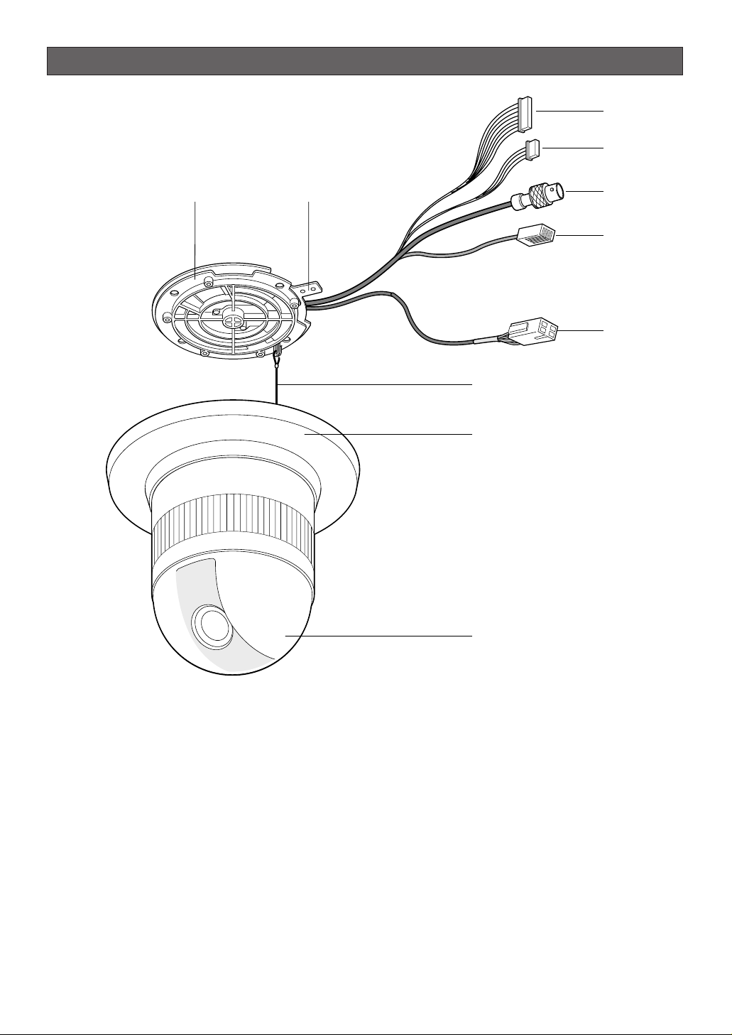
CONSTRUCTION
q Alarm Input Connector
w Alarm Output Connector
e Video Output Connector
r Network Port
t Power Cable
y Camera Mounting Base (Color: Gray)
u Panning Starting Point
i Fall Prevention Wire
o Decoration Cover
!0 Dome Cover
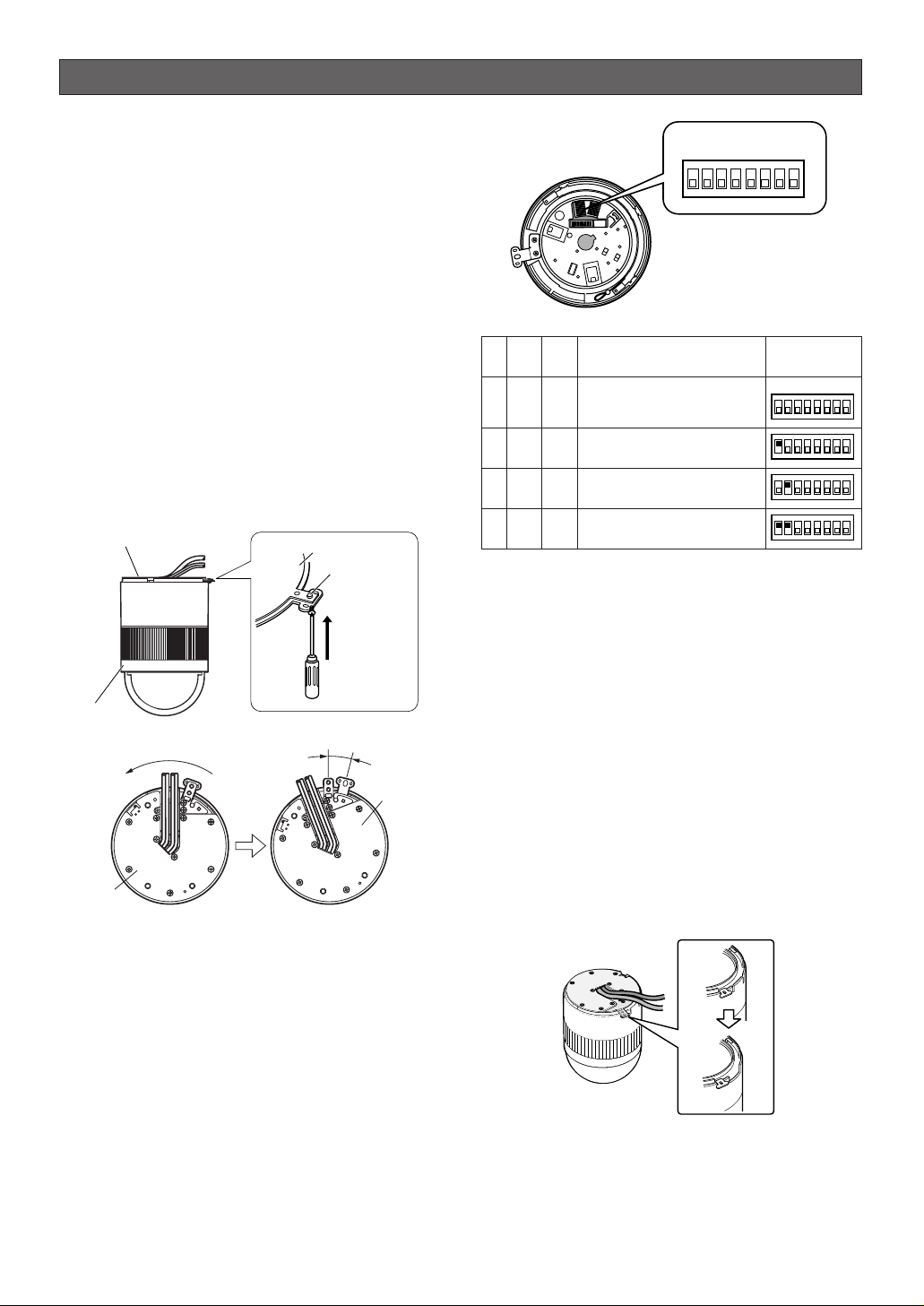
Note: All DIP switches except SW1 and SW2 should
always be set to "off".
3. Assemble the Camera
Reverse the disassembly procedure. Take care not
to cut any cables.
Precaution
Be sure to select a ceiling board strong enough to support 4 times the total weight of the camera.
a. Sideway Cable Exit
Prepare a cutout in the diecast case and decoration cover as shown in the following figures.
Cutout in Diecast Case
StatusNo.
-10-
INSTALLATION
Precautions
• The following installation and connection work
should be done by qualified service personnel or
system installers and should conform to all local
codes.
• Be sure to switch the camera off before installation
and connection.
• Do not install the camera near the air outlet of an
air conditioner.
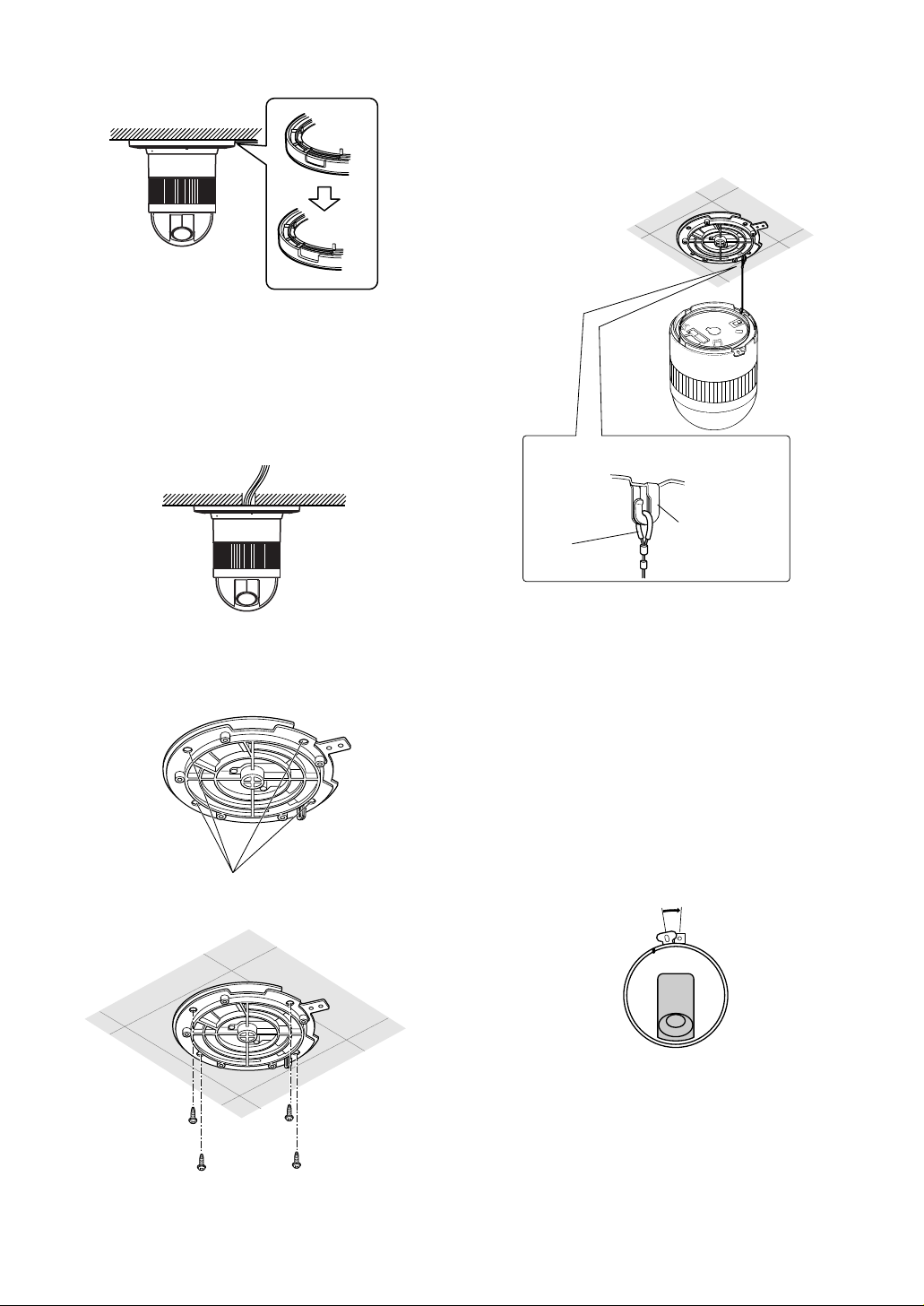
1. Disassembling the Camera
(1) Loosen the fixing screw to separate the cam-
era mounting base from the camera. Push up
the screwdriver once before removing the
screw.
(2) Turn the camera mounting base approximately
15 degrees counterclockwise and remove the
base from the camera.
2. Setting Switches
The camera is provided with an 8-bit DIP switch.
The 8-bit DIP switch is used to return the camera to
the factory default settings. Switch settings are
read into the camera when the power is turned on.
Make sure to turn the camera off, then turn it back
on after changing the switch settings. Switch positions and functions are shown below.
Note: When taking these procedures, keep the
power turned on until initialization of the
Camera Servo Control is completed.
Dip SW
Position
DIP
SW1
DIP
SW2
1 OFF OFF Normal
1234ON5678
8-bit DIP SW
Normal Position
1234ON5678
1234ON5678
1234ON5678
2
ON
OFF Initializing the setup menu
3 OFF
ON
Initializing HTML files
4
ON ON
Initializing the setup menu
& HTML files
8-bit DIP SW
1234ON5678
Camera mounting base
Camera
Turn 15°
Camera mounting
base
Then
Fixing screw
Loosen and
push
15°
Remove
from the
camera
Camera
mounting base
-11-
Cutout in Decoration Cover
Note: Remove sharp edges to protect the cables.
b. Top Cable Exit
Prepare a hole in the ceiling board to run the
cables.
1. Mark the mounting holes on the ceiling, using the
removed camera mounting base as a template.
2. Fix the camera mounting base to the ceiling with
four screws (not provided, M4).
3. Hook the fall prevention wire on the camera mounting base.
Cautions:
• Use the supplied dust protection sheet if the camera mounting base is liable to be exposed to a
dusty atmosphere. Remove the cover from the dust
protection sheet, then stick the sheet on the camera mounting base.
• Remove the sheet before mounting the camera on
the base.
• While the camera is separated from the base, keep
the camera in the supplied polyethylene sack.
4. Mount the camera on the camera mounting base
and rotate the camera clockwise.
Be sure to match the wire with the fall
prevention wire fixing angle as shown below.
Marking
Ring of the
fall prevention
wire
Fall prevention
wire fixing angle
15°
-12-
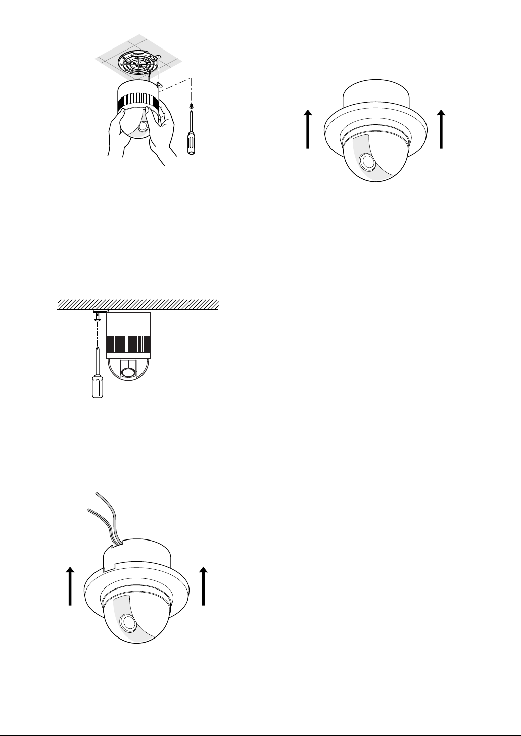
5. Tighten the fixing screw M3 (provided).
Notes:
(1) Tighten the camera fixing screw with a screw-
driver.
(2) Follow the instructions given here to ensure
that the camera and camera mounting base
are installed safely.
(3) When removing the camera from the camera
mounting base, loosen and press up the camera fixing screw (M3) by using a screwdriver.
6. Fix the decoration cover to the camera mounting
base.
a. Sideway Cable Exit
Pass the cables through the cutout made in the
diecast case and decoration cover.
b. Top Cable Exit
Push the decoration cover against the camera
mounting base.
Contact
Insert
Up
A
Approx.
3 mm (0.1 inch)
Insert the wire until A position
and clamp the contacts.
Wire
Note: When powered up, the unit performs a self-
check (including one panning, tilting, zooming
and focusing operation).
• 24 V AC Power Supply Connection
Prepare the individual conductors for clamping. Use
MOLEX band tool part number 57027-5000 (for ULStyle Cable UL1015) or 57026-5000 (for UL-Style
UL1007) for clamping the contacts.
After clamping the contacts, push them into the proper
holes in the accessory connector of this camera until
they snap in place.
Cautions:
• Shrinking the cable-entry seal is a one-time procedure. Do not shrink the cable-entry seal until it has
been ascertained that the unit is functioning.
• CONNECT THIS TO 24V AC CLASS 2 POWER
SUPPLY ONLY.
How to Assemble the Cable with the Accessory
Connector
Strip back the cable jacket approx. 3 mm (0.1 inch) and
separate the individual conductors.
Copper wire size
(AWG)
-13-
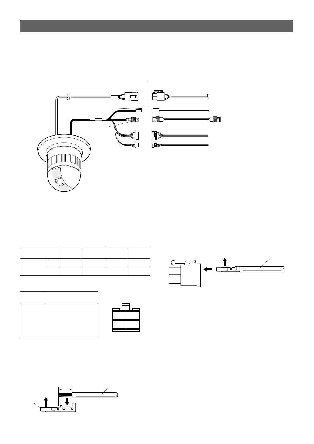
CONNECTIONS
Precautions
• The following connections should be made by qualified service personnel or system installers in accordance with
all local codes.
• See the reverse side of the cover page for mains lead connection.
✻ The coaxial cable length (RG-6/U, 5C-2V) for the connection is up to 1 200
meters (4 000 ft.)
To VIDEO IN
(CAMERA IN)
Video output
24 V AC
BNC plug
Coaxial cable
Ethernet cable
Data port
BNC plug
Alarm in
Alarm out
To sensors
To indicators
24 V AC cable
Adapter
75
Recommended wire gauge sizes for 24 V AC line
#24
(0.22mm
2
)
Length
of cable
(approx.)
(m)
(ft)
#22
(0.33mm
2
)
#20
(0.52mm2)
#18
(0.83mm2)
20 30 45
65 100 160 260
Accessory Connector Information
Pin no. Power source
1
2
3
4
24 V AC LIVE
24 V AC NEUTRAL
Ground
Not use
Up
Contact
Wire
3
4
1
2
-14-
•Ethernet Connection
• ALARM IN Connections
An 8-pin and a 4-pin harness are supplied with the
camera as standard accessories. Connect external
sensors to this connector. Input specifications are
low-active, non-voltage contact (ON when active)
or open collector (Low when active). The table
below shows wire colors versus pin functions.
• ALARM OUT/AUX OUT Connections
Connect an external device, for example, a buzzer
or lamp, to this connector. Output specifications
are low-active, open-collector and a drive capacity
of 16 V DC 100 mA maximum. The table below
shows wire colors versus pin functions.
Note: Use a relay if the voltage or current of the
connected device exceeds the ratings.
• Video Cable Connections
The maximum extensible coaxial cable length
between the camera and the monitor is shown in
the table.
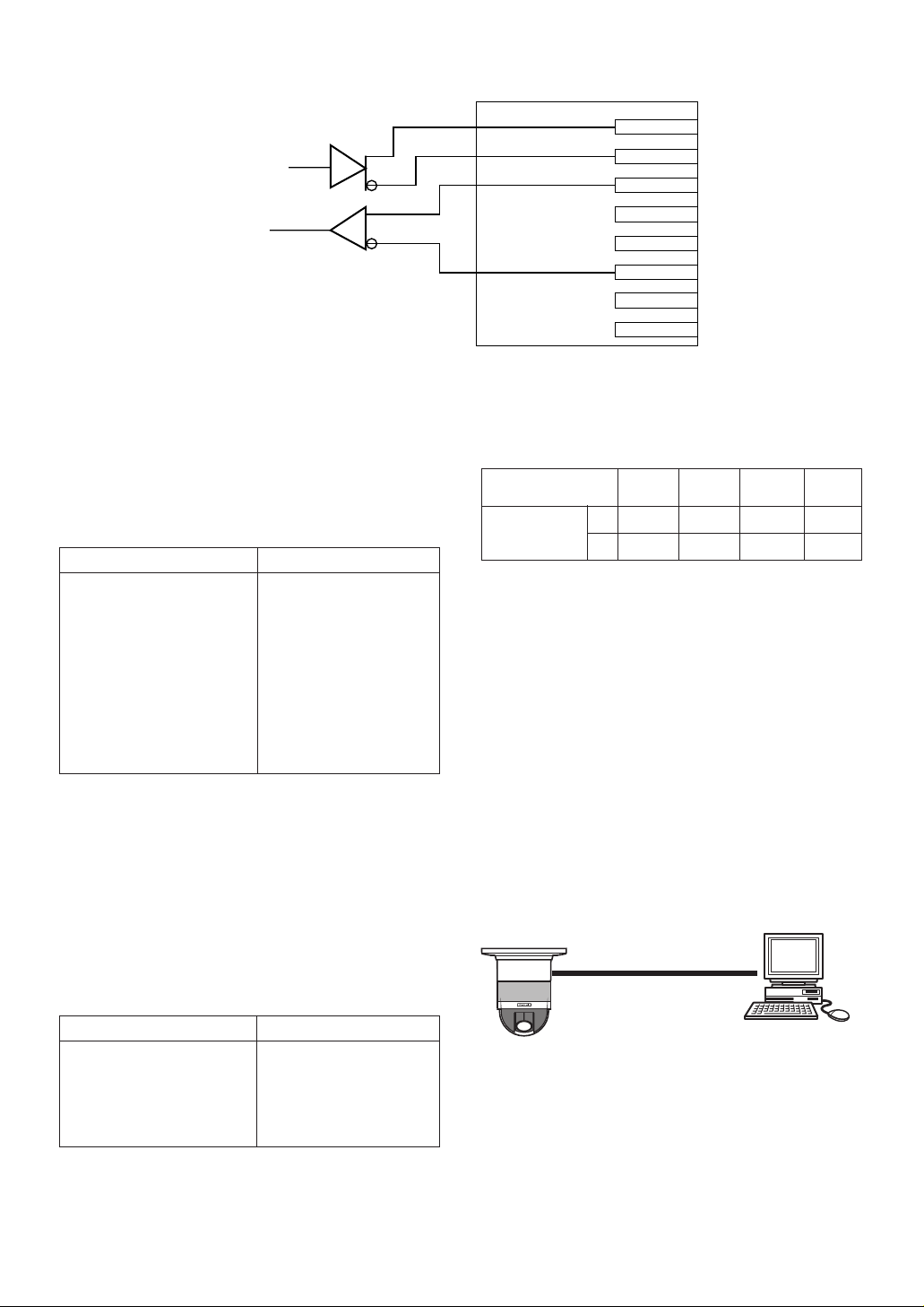
Network Connections
Prior to connections, specify the connection type and
prepare relevant devices and cables.
Notes:
• We recommend that you use connection type 1 or
2 when setting up the network address of the camera.
• Be sure to unplug or switch off all the devices
before starting connections.
•Direct Connection to PC (Type 1)
Use a category 5 cross-type network cable to connect
the camera directly with the PC.
Necessaries: Cross-type network cable (Category 5)
IN 1
GND
IN 2
GND
GND
GND
GND
GND
Black
Brown
Red
Orange
Yellow
Light Blue or Green
Blue
Purple
Wire Color Function
Alarm IN (8-pin)
Wire Color
Gray
White
Pink
Yellow Green or Light Blue
Function
Alarm OUT
GND
AUX OUT
GND
Alarm OUT/AUX OUT (4-pin)
Type of RG-59/U RG-6/U RG-11/U RG-15/U
coaxial cable (3C-2V) (5C-2V) (7C-2V) (10C-2V)
Recommended (m) 250 500 600 800
maximum
cable length (ft) 825 1 650 1 980 2 640
Data transmission
Data reception
Red
Orange
Yellow
Green
TX +
TX –
RX +
RX –
q
w
e
r
t
y
u
i
Network Cable (Cross type)
PC
 Loading...