

(Lens : option)
Before attempting to connect or operate this product,
please read these instructions carefully and save this manual for future use.
Model No. WV-NP472
Color CCTV Camera
Operating Instructions
(Lens: Option)
day/night
SDII
-2-
WARNING: To prevent fire or electric shock hazard, do not expose this appliance to rain or moisture. The apparatus shall not be exposed
to dripping or splashing and that no objects filled with liquids, such as vases, shall be placed on the apparatus.
The lightning flash with arrowhead
symbol, within an equilateral triangle, is
intended to alert the user to the presence of uninsulated "dangerous voltage" within the product's enclosure that
may be of sufficient magnitude to constitute a risk of electric shock to persons.
The exclamation point within an equilateral triangle is intended to alert the
user to the presence of important operating and maintenance (servicing)
instructions in the literature accompanying the appliance.
The serial number of this product may be found on the top
of the unit.
You should note the serial number of this unit in the space
provided and retain this book as a permanent record of your
purchase to aid identification in the event of theft.
Model No. WV-NP472
Serial No.
Warning:
This equipment generates and uses radio frequency energy
and if not installed and used properly, i.e., in strict accordance with the instruction manual, may cause harmful
interference to radio communications. It has been tested
and found to comply with the limits for a Class A computing
device pursuant to Subpart J of Part 15 of FCC Rules,
which are designed to provide reasonable protection
against such interference when operated in a commercial
environment.
CAUTION:
TO REDUCE THE RISK OF ELECTRIC SHOCK, DO
NOT REMOVE COVER (OR BACK). NO USER SERVICEABLE PARTS INSIDE.
REFER SERVICING TO QUALIFIED SERVICE PERSONNEL.
CAUTION
RISK OF ELECTRIC SHOCK
DO NOT OPEN
SA 1965
SA 1966
For U.S.A

-3-
IMPORTANT SAFETY INSTRUCTIONS
1) Read these instructions.
2) Keep these instructions.
3) Heed all warnings.
4) Follow all instructions.
5) Do not use this apparatus near water.
6) Clean only with dry cloth.
7) Do not block any ventilation openings. Install in accordance with the manufacturer's instructions.
8) Do not use near any heat sources such as radiators, heat registers, stoves, or other apparatus (including amplifiers) that produce heat.
9) Do not defeat the safety purpose of the polarized or grounding-type plug. A polarized plug has two blades with
one wider than the other. A grounding-type plug has two blades and a third grounding prong. The wide blade or
the third prong are provided for your safety. If the provided plug does not fit into your outlet, consult an electrician for replacement of the obsolete outlet.
10) Protect the power cord from being walked on or pinched particularly at plugs, convenience receptacles and the
points where they exit from the apparatus.
11) Only use attachments/accessories specified by the manufacturer.
12) Use only with the cart, stand, tripod, bracket, or table specified by the manufacturer, or sold with the apparatus.
When a cart is used, use caution when moving the cart/apparatus combination to avoid injury from tip-overs.
13) Unplug this apparatus during lightning storms or when unused for long periods of time.
14) Refer all servicing to qualified service personnel. Servicing is required when the apparatus has been damaged
in any way, such as power-supply cord or plug is damaged, liquid has been spilled or objects fallen into the
apparatus, the apparatus has been exposed to rain or moisture, does not operate normally, or has been
dropped.
S3125A

-4-
CONTENTS
IMPORTANT SAFETY INSTRUCTIONS ....................... 3
PREFACE ..................................................................... 5
Features .................................................................... 5
Computer Requirements .......................................... 5
Trademarks ............................................................... 5
Document Convention .............................................. 5
PRECAUTIONS ............................................................ 6
MAJOR OPERATING CONTROLS AND
THEIR FUNCTIONS ..................................................... 7
INSTALLATIONS .......................................................... 8
Mounting and Adjusting the Lens ............................. 8
Mounting the Camera ............................................... 9
CONNECTIONS ........................................................... 10
Power-in Connections ............................................... 10
Video Cable Connections ......................................... 10
Control Terminal Connections .................................. 10
Network Connections 10
OPERATING THE CAMERA ......................................... 12
Access from the PC .................................................. 12
Preliminary Setup ...................................................... 12
Access from the Camera/System Device ................. 13
PRIOR TO SETUP ........................................................ 14
Buttons Used for Setup Menus ................................. 14
Camera Setup Menus ............................................... 14
SETTING PROCEDURES ............................................. 16
SETUP SELECTION ..................................................... 16
CAMERA SETUP MENU .............................................. 16
1. Camera Identification (CAMERA ID) Setting ........ 16
2. Light Control Setting (ALC/ELC) ........................... 17
3. Shutter Speed Setting (SHUTTER) ....................... 18
4. Gain Control Setting
(AGC ON (DNR-H, DNR-L)/OFF) 18
5. Electronic Sensitivity Enhancement
(SENS UP) ............................................................ 19
6. White Balance Setting (WHITE BAL) .................... 19
7. Motion Detector Setting (MOTION DET) ............... 20
8. Lens Drive Signal Selection (LENS DRIVE) .......... 20
9. Date Display (Clock) Setting ................................ 20
10. Special Menu ........................................................ 21
NETWORK SETUP ....................................................... 22
SETUP FROM THE PC ................................................. 23
PREPARATIONS FOR THE PC ................................. 23
■ Connections .......................................................... 23
■ Network Setup of the PC ....................................... 24
■ Network Setup of the Camera ............................... 25
■ Network Setup Parameters vs.
Connection Type ................................................... 26
CAMERA SETUP FROM THE PC ................................. 30
■ Camera Setup Menus ........................................... 31
PC ORIENTED SETUP ................................................. 32
■ Image Setup ......................................................... 32
■ Alarm Setup .......................................................... 32
■ FTP Client Setup ................................................... 33
■ User Setup ............................................................ 34
■ Host Setup ............................................................ 35
■ System Setup ........................................................ 35
INITIALIZING ............................................................... 36
■ Initializing the Camera Menu ................................ 36
■ Initializing the Setup Menu .................................... 36
■ Initializing HTML windows .................................... 36
VIEWING PICTURES .................................................... 37
■ Image Quality Selection ........................................ 37
■ Still Picture Storage to the PC ............................... 37
■ Monochrome Mode ............................................... 38
ALARM FUNCTIONS ................................................... 39
■ When an Alarm Arises .......................................... 39
■ Transferring Picture Files ...................................... 39
■ Canceling Alarm Display ...................................... 40
■ VMD Setup ............................................................ 40
■ Reviewing Alarm Pictures ..................................... 41
■ Resetting Alarm .................................................... 42
AUXILIARY OUTPUT CONTROL ................................. 43
■ Auxiliary Output Control ........................................ 43
TROUBLESHOOTING .................................................. 44
SPECIFICATIONS ........................................................ 45
OPTIONAL ACCESSORIES ......................................... 46
STANDARD ACCESSORIES ........................................ 46

-5-
Features
• 10/100BASE-T terminal enables your PC to view
camera images via the network.
• SD II (super dynamic) system allows a wide range
of 46 dB while preventing images from being
spoiled by strong background light.
• High resolution supported by a 1/3” CCD having
380 000 pixels
•A 0.8 lx illuminance is allowed when using a F=1.4
lens, thanks to low-noise design. A 0.4 lx illuminance is allowed when using an aspherical F=0.75
large-aperture lens.
• Switchable video mode between color and monochrome in response to light inputs
• Built-in motion detector generates an alarm when
video levels change certain amount.
Computer Requirements
The following environments are essential for your computer to view camera pictures or to set up parameters.
Computer: PC/AT compatible
OS: One of the following should be installed.
Microsoft Windows98 Second Edition
Microsoft Windows2000 Professional Service
Pack2
Microsoft Windows Millennium Edition
Microsoft Windows XP
Microsoft Windows NT Workstation 4.0 Service
Pack6a
CPU: Pentium II (300 MHz) or faster
Memories: 128 MB or higher
Network Interface: The following protocols should be
supported by a 10/100Mbps Ethernet card
installed.
TCP/IP, HTTP, FTP, SMTP, DNS, DHCP
Browser: One of the following should be installed.
Internet Explorer 5.01SP2, 5.5, 5.5SP2, 6.0
Netscape Communicator 4.73, 4.78
Trademarks
• Adobe, Adobe logos, and Acrobat are registered
trademarks of Adobe Systems Incorporated in the
U.S. and/ or other countries.
• Microsoft, Windows, Windows NT, and Windows XP
are registered trademarks of Microsoft Corporation
in the U.S. and/or other countries.
• Netscape, Netscape Navigator, Netscape ONE,
the Netscape N and Ship’s Wheel logos are registered trademarks of Netscape Communications
Corporation in the U.S. and other countries. Other
Netscape product names used in this document
are also trademarks of Netscape Communications
Corporation and may be registered outside the
U.S.
• Ethernet is a registered trademark of Xerox
Corporation.
• Other names of companies and products contained in these operating instructions may be
trademarks or registered trademarks of their
respective owners.
• Distributing, copying, disassembling, reverse complying, reverse engineering, and also exporting in
violation of export laws of the software provided
with this product, is expressly prohibited.
Document Convention
These operating instructions use the following convention when describing the uses and operations.
• Windows 98 stands for Microsoft Windows 98
Second Edition.
• Windows 2000 stands for Microsoft Windows 2000.
• Windows ME stands for Microsoft Windows
Millennium Edition.
• Windows NT stands for Microsoft Windows NT
Workstation 4.0 Service Pack 6a.
• Windows XP stands for Microsoft Windows XP.
Panasonic’s WV-NP472 camera features functions for network access besides high-level picture quality developed for
conventional video surveillance purposes.
PREF ACE

-6-
1. The installation should be made by qualified
service personnel or system installers.
2. Do not attempt to disassemble the camera.
To prevent electric shock, do not remove screws or
covers.
There are no user-serviceable parts inside. Ask
qualified service personnel for servicing.
3. Handle the camera with care.
Do not abuse the camera. Avoid striking, shaking,
etc. The camera could be damaged by improper
handling or storage.
4. Do not use strong or abrasive detergents when
cleaning the camera body.
Use a dry cloth to clean the camera when dirty.
When the dirt is hard to remove, use a mild detergent and wipe gently. Then wipe off the remaining
detergent with a dry cloth.
5. Clean the CCD faceplate with care.
Do not clean the CCD with strong or abrasive
detergents. Use lens tissue or a cotton tipped
applicator with ethanol.
6. Never face the camera toward the sun.
Do not aim the camera at bright objects. Whether
the camera is in use or not, never aim it at the sun
or other extremely bright objects. Otherwise,
blooming or smear may be caused.
7. Do not operate the camera beyond the specified
temperature, humidity or power source ratings.
Use the camera at temperatures between –10 °C
and +50 °C (14 °F - 122 °F), and humidity below
90 %. The input power source is 12 V DC.
8. To prevent fire or electric shock hazard, use a
UL listed cable (VW-1, style 1007) for the 12V DC
input terminal.
PRECAUTIONS
t
i
yo
u
q w e
r
WV
–
NP472
ALARM IN
ALARM OUT
AUX OUT
DAY/NIGHT IN
GND
AB
VIDEO OUT
RCV
LINK
10BASE-T/
100BASE-TX
POWER
DC 12V
IN
!3
!4
!2!1
!0
-7-
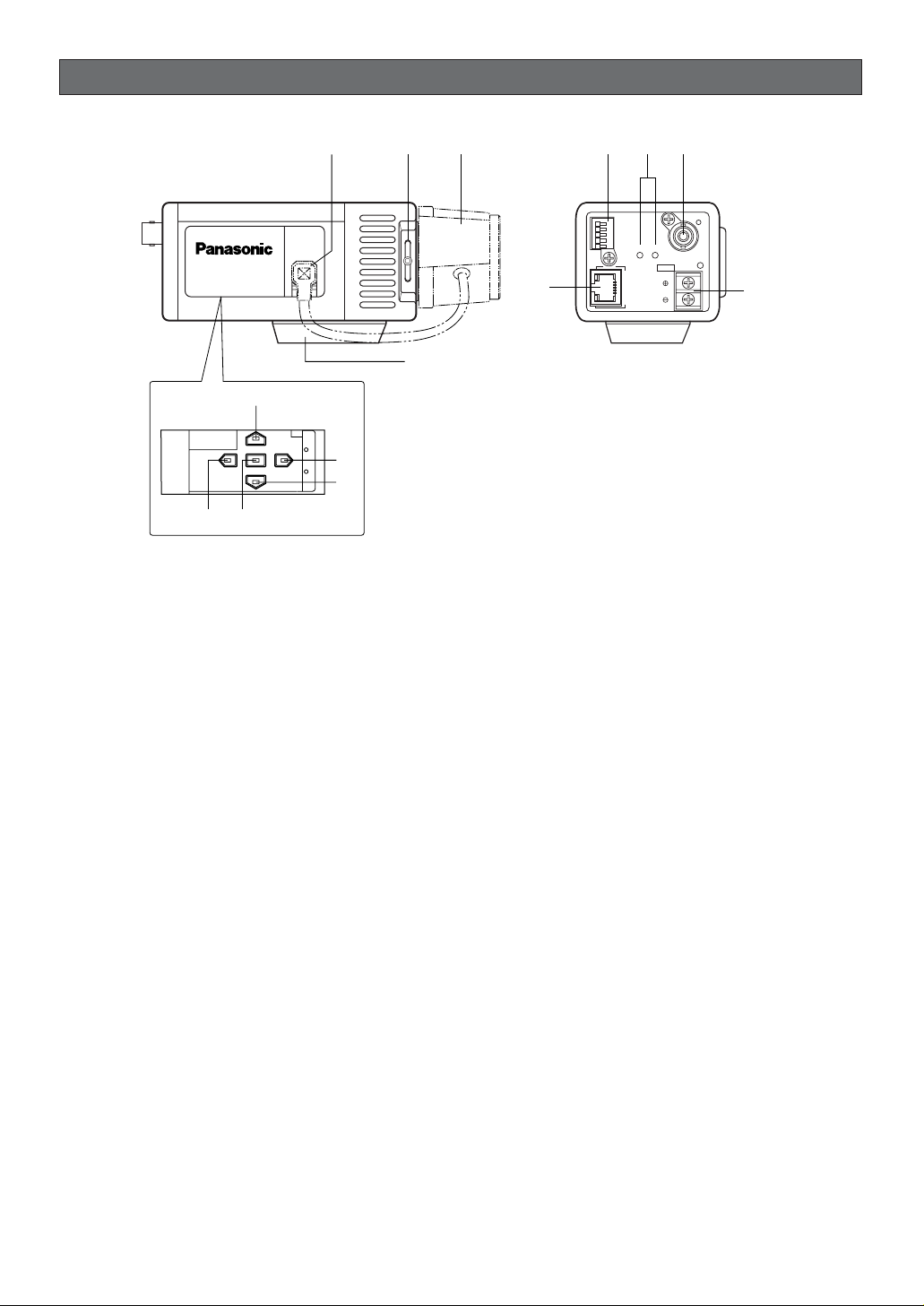
MAJOR OPERATING CONTROLS AND THEIR FUNCTIONS
Slide the panel to the left until it locks.
q Auto Iris Lens Connector
Connects the auto iris lens with a 4-pin male connector supplied as a standard accessory (Part No.
YFE4191J100).
w Flange-back Adjusting Ring & Screw
Adjusts the back focal length and picture focus.
e Lens (Option)
r Camera Mounting Adapter
Mounts the camera onto a mounting bracket.
t Down Button (K)
Moves the cursor downward and selects items in
the CAM SET UP menu.
y Left Button (L)
Moves the cursor leftward, selects the mode and
adjusts some levels.
u Up Button (J)
Moves the cursor upward and selects items in the
CAM SET UP menu.
i Right Button (M)
Moves the cursor rightward, selects the mode and
adjusts some levels.
o Set Button (I)
Activates an item selected in the CAM SET UP
menu.
!0 Network Port with Indicators (10BASE-
T/100BASE-TX/RCV/LINK)
Connects to a PC or a network via a hub with a
10BASE-T/100BASE-TX cable attached RJ-45 connector. Indicators will light up while receiving data
(RCV) or establishing communications (LINK).
!1 Control Terminals
Connects respective devices.
ALARM IN: Alarm sensor, ALARM OUT: Recording
device/alarm indicator, AUX OUT: External device,
DAY/NIGHT IN: Optical sensor, GND: Signal
ground
!2 Reset Button (A, B)
The button A, along with the J and K buttons,
resets the network setup parameters when you
hold down these buttons for 6 seconds in the
power-on state.
The button B resets the HTML files and alarm mail
setup in the same manner as the button A.
Note: Never press both the reset buttons A and B
at a time.
!3 Video Output Connector (VIDEO OUT)
Supplies analog video signal (composite) to the
connected device.
!4 Power In Terminal and Power Indicator
(DC 12V IN, POWER)
Connects to a DC power supply using proper
cables. The power indicator lights up when power
is supplied.
-8-
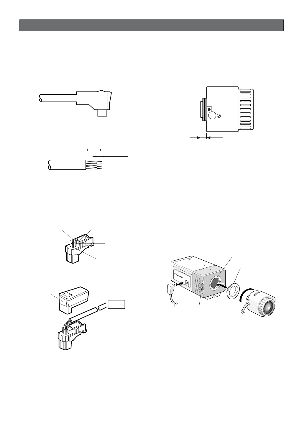
• Mounting the Lens
Notes:
• Using the lens having improper protrusion will
damage the camera. The protrusion of the lens into
the camera body should be within the length indicated in the figure.
• Secure both the lens and camera with the supporter (not supplied) if a lens heavier than 450 g
(0.99 lbs) is mounted.
1. Attach the supplied C-mount adapter when using a
C-mount lens.
The camera at the factory shipment can accept
only a CS-mount lens.
2. Jump to step 3 if the lens has focus adjusting
mechanism. Loosen the flange-back screw, and
rotate the adjusting ring down until it stops on the
side of the camera.
3. Mount the lens.
4. Connect the lens cable to the auto iris connector
on the side of the camera.
Mounting and Adjusting the Lens
• Replacement of Auto Iris Lens Connector
If necessary, replace the existing lens connector with
the type YFE419J100 supplied.
1. Cut the existing lens connector from the iris control
cable at its end.
2. Process the cable end as shown in the figure.
3. Solder each wire to the pin.
Pin #1: Red/Power
Pin #2: Not used
Pin #3: White/Video
Pin #4: Black/GND, Shield
4. Attach the cover to the connector.
INSTALLATIONS
Pin 3
Pin 1
Rib
Pin 4
Pin 2
Cover
Lens
C-mount: Less than 13 mm (1/2”)
CS-mount: Less than 8 mm (5/16”)
Flange-back
Adjusting Ring & Screw
C-mount Adapter
Lens Mount
8 mm (5/8")
2 mm (1/16")
W
V
-
NP472
-9-
• Flange-back Adjustment
The adjustment is required only when a lens without
focus-adjusting mechanism is mounted, or when a lens
with adjusting mechanism is mounted and focus that is
more accurate is needed.
1. Loosen the flange-back fixing screw on the flangeback adjusting ring.
2. Turn the flange-back adjusting ring to obtain a
focused point while watching the monitor screen.
3. Tighten the flange-back fixing screw softly and
securely.
Note: The object may be out of focus when using a
source of near-infrared light rather than using
the visible light.
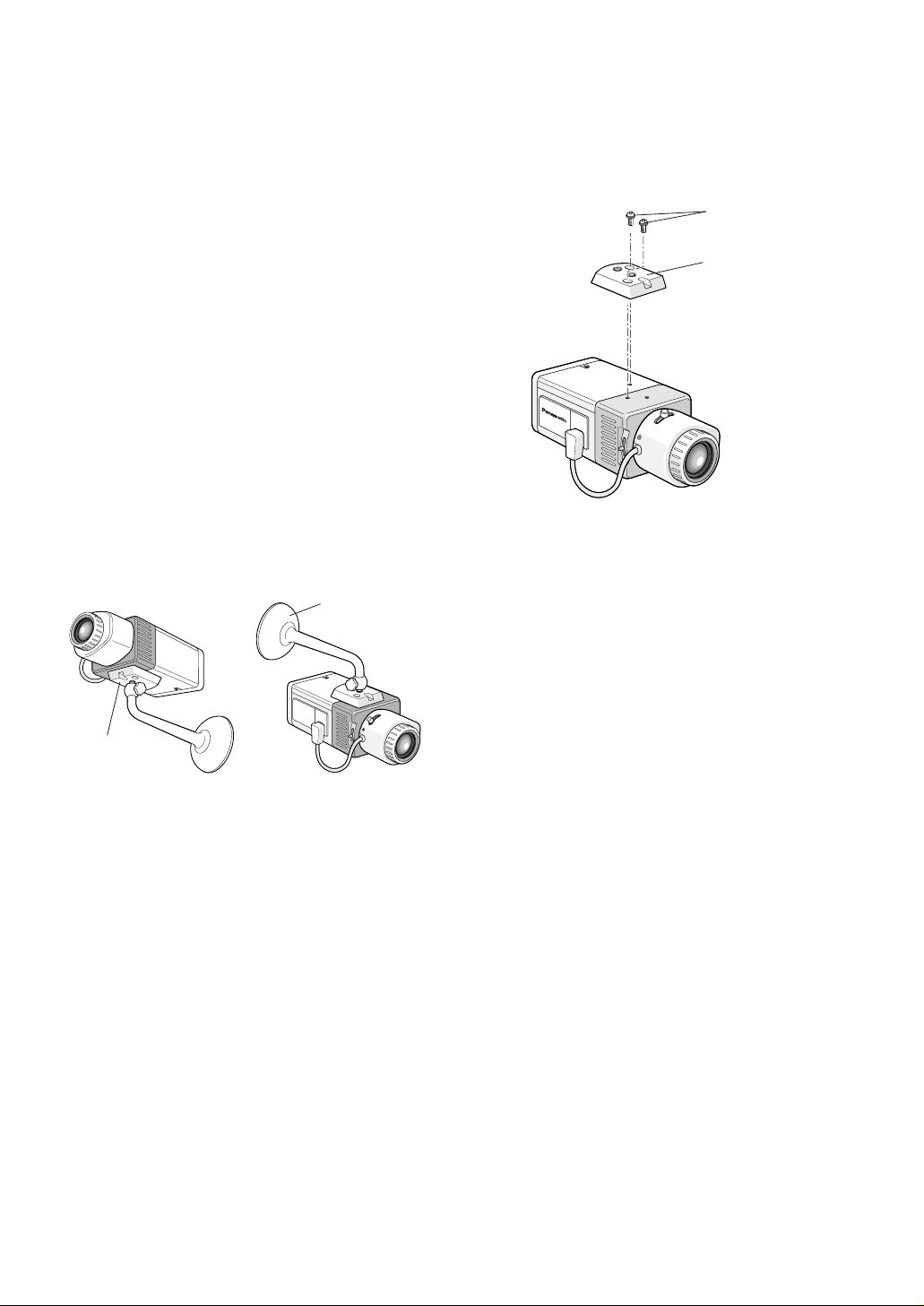
Mounting the Camera
The mounting adapter can be secured on either the top
or bottom (at the factory shipment) of the camera. The
mounting hole is a standard photographic pan-head
screw size (1/4”-20).
• Mounting from the Bottom
1. Secure the camera on the camera-mounting bracket (locally procured), referring to the manual included with the bracket.
• Mounting from the Top
1. Remove the mounting adapter from the bottom of
the camera.
2. Attach the mounting adapter on top of the camera
as shown in the figure.
3. Secure the camera to the camera-mounting bracket (locally procured), referring to the manual included with the bracket.
Note: Use the original two screws to attach the
mounting adapter on the camera. Using shorter ones may cause the camera to fall down, or
longer ones may damage the inside of the
camera.
• Pictures Upside-down
You can reverse the picture upside-down in the menu
setup when it is necessary.
Note: The right and left of the picture are not reversed.
NP472
Fixing Screws
Mounting Adapter
Camera-mounting
bracket (Locally
procured)
WV
-
NP472
Adapter on the
bottom at the
factory shipment
-10-
Power-in Connections
Notes:
• Use only a class-2 power supply suitable to the
voltage and current required by the camera. See
specifications.
• Use a UL listed cable (VW-1, style 1007) to prevent fire or electric shock.
You can use the formula below to select the power
supply, and power cable. The supplied voltage to the
power-in terminals must be between 10.8V and 16V.
10.8V(minimum) ≤ VA – 2RLI ≤ 16V (maximum)
VA: Output voltage of power supply
R: Resistance (Ω/m) (Ω/ft), see table
L: Cable length (m) (ft)
I: Consumption current (A), see specifications
CONNECTIONS
Copper wire #24 #22 #20 #18
size (AWG) (0.22 mm2) (0.33 mm2) (0.52 mm2) (0.83 mm2)
Resistance 0.078 0.050 0.030 0.018
Ω/m
Resistance 0.026 0.017 0.010 0.006
Ω/ft
Resistance of copper wire [at 20 °C (68 °F)]
1. Connect the power cable to the terminals while
identifying the polarity.
2. Fasten the screws.
Video Cable Connections
The maximum extensible coaxial cable length between
the camera and the monitor is shown in the table.
Type of RG-59/U RG-6/U RG-11/U RG-15/U
coaxial cable (3C-2V) (5C-2V) (7C-2V) (10C-2V)
Recommended (m) 250 500 600 800
maximum
cable length (ft) 825 1 650 1 980 2 640
12 V DC
(10.8 V - 16 V)
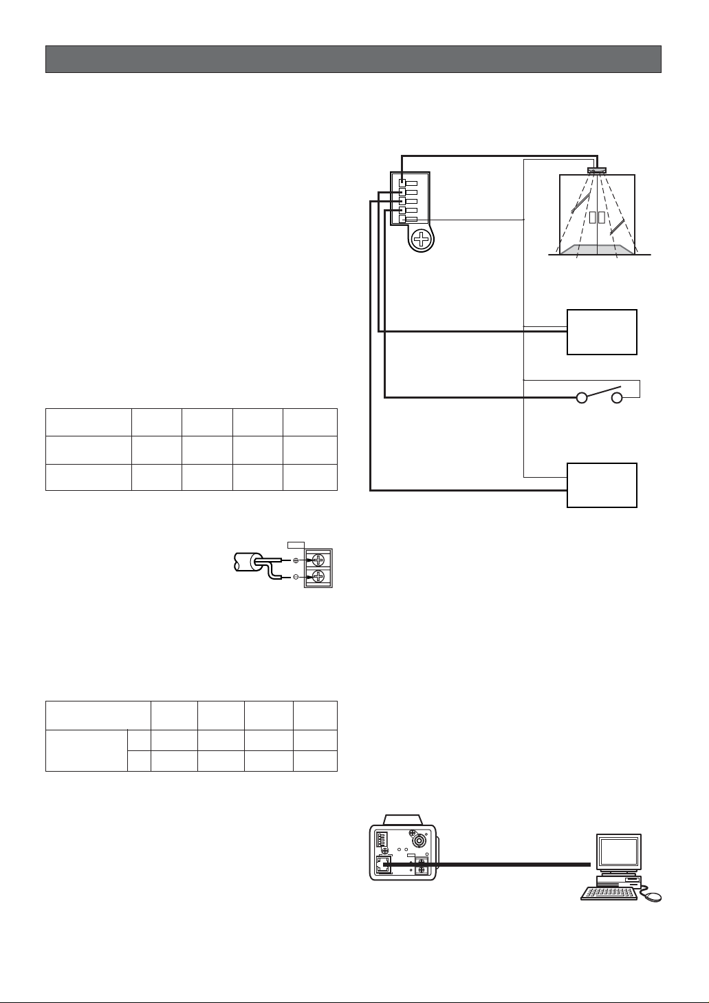
Control Terminal Connections
Connect relevant devices as shown in the figure.
ALARM IN
ALARM OUT
AUX OUT
DAY/NIGHT IN
GND
Sensor
Recording device e.g. VCR
Optical sensor
ON: B/W,
OFF: Color
Aux devices e.g. lamp
ALARM IN
ALARM OUT
DAY/NIGHT IN
AUX OUT
Notes:
• See specifications for each terminal.
• Use a relay when the connected device exceeds
the ratings in voltage or current.
• The optical sensor validates the Day/Night function
if B/W is set to EXT in the setup menu.
Network Connections
Network Connection Types
• Use a router or switching hub when multiple cameras are connected.
• Use a router handling PPPoE (PPP over Ethernet)
when running PPPoE to connect with the Internet,
because the camera is incapable of it.
• Use network cables complying with category5.
•Direct Connection to PC (Type 1)
DC 12V
IN
ALARM IN
ALARM OUT
AUX OUT
DAY/NIGHT IN
GND
AB
VIDEO OUT
POWER
DC 12V
RCV
IN
10BASE-T/
100BASE-TX
LINK
Network Cable (Cross type)
PC
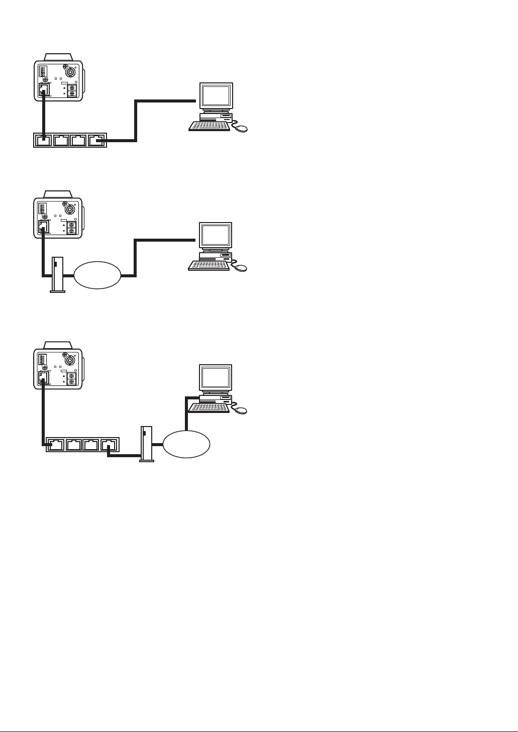
• Connection to Intranet (Type 2)
• Connection to Internet (Type 3)
• Connection to Internet (Type 4)
-11-
Note: Apply proper measures to protect the camera
from thunderbolts if your system is possibly damaged. As a protection, for example, use a converter
that changes electric signals to optical signals
complying with 10BASE-F/100BASE-FX.
ALARM IN
ALARM OUT
AUX OUT
DAY/NIGHT IN
GND
AB
VIDEO OUT
POWER
DC 12V
RCV
IN
10BASE-T/
100BASE-TX
LINK
Network Cable
(Straight type)
Switching Hub
ALARM IN
ALARM OUT
AUX OUT
DAY/NIGHT IN
GND
AB
VIDEO OUT
POWER
DC 12V
RCV
IN
10BASE-T/
100BASE-TX
LINK
Network Cable
(Straight type)
PC
(16 clients maximum)
Internet
DSL/CATV Modem
ALARM IN
ALARM OUT
AUX OUT
DAY/NIGHT IN
GND
AB
VIDEO OUT
POWER
DC 12V
RCV
IN
10BASE-T/
100BASE-TX
LINK
Network Cable
(Straight type)
Switching Hub or Router
DSL/CATV Modem
PC
(16 clients maximum)
PC
(16 clients maximum)
Internet
-12-
OPERATING THE CAMERA
You can operate the camera in two ways: from the PC
by way of network, or locally from the camera or system
device.
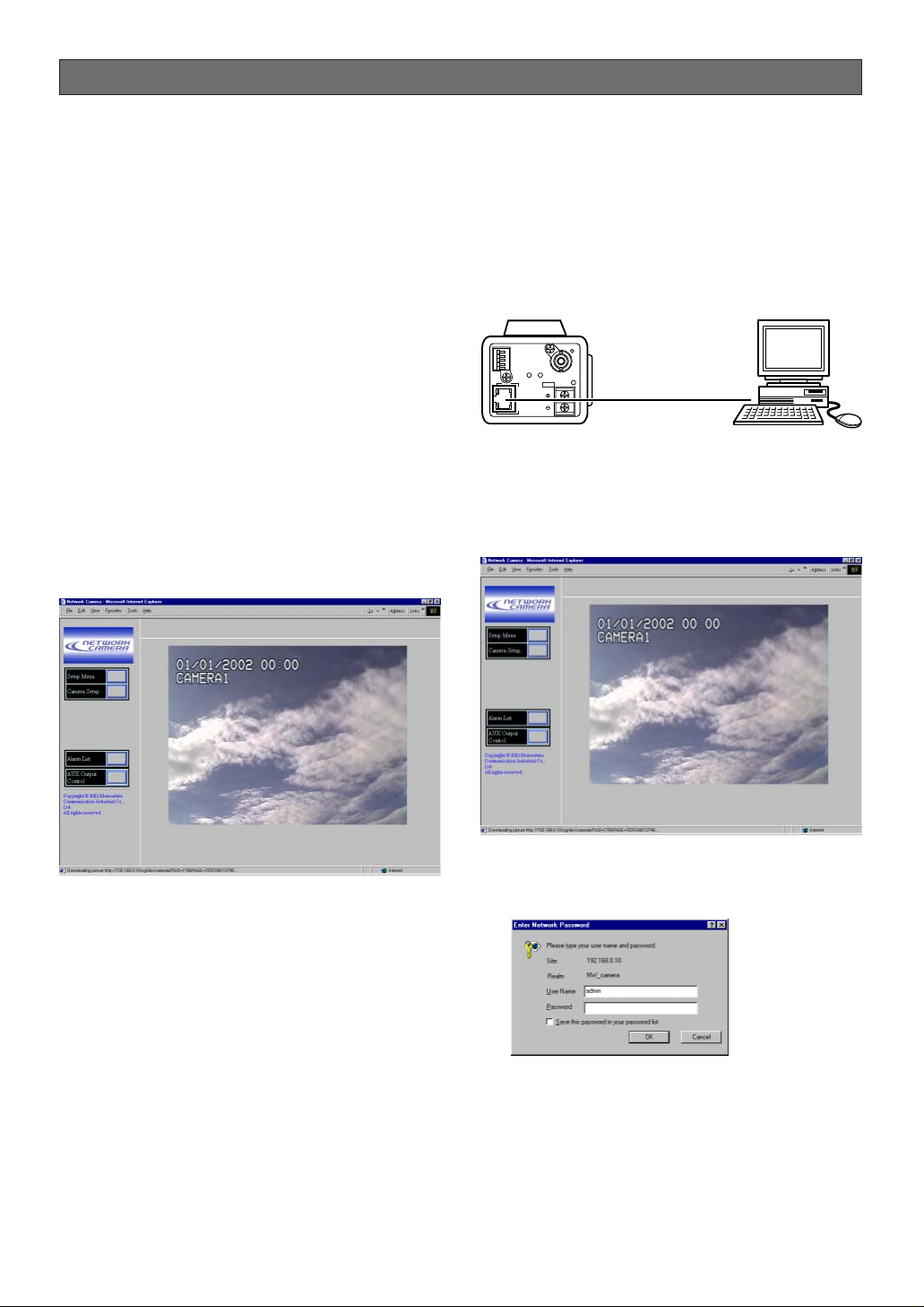
Access from the PC
Your PC can access the camera to view images and to
set up menus.
Prior to operating from the PC, confirm that connections
are made properly as shown in the previous page,
CONNECTIONS.
1. Start up the PC.
2. Start up the Web browser, Internet Explorer or
Netscape Communicator.
3. Enter the IP address of the camera in the address
bar.
The camera address is set to 192.168.0.10 at the
factory default setting.
4. Press Enter on the keyboard.
5. The main page of the WV-NP472 camera will
appear on the display.
Note: Adobe Acrobat Reader should have been
installed on your PC to open the manual. Visit
the home pages of Adobe Systems Incorporated.
Preliminary Setup
Prior to connection to the system, you need to set up a
network address for the camera by one-to-one connection with a PC.
Parameters at the factory default are set as follows.
IP address: 192.168.0.10
Subnet mask: 255.255.255.0
Gateway: 192.168.0.1
HTTP port number: 80
1. Enter an IP address, “http://192.168.0.10” for
example, in the address bar of the browser to display the main page of the WV-NP472 camera.
2. Click the Setup Menu button. The authentication
dialog appears.
3. Enter “admin” in the user name line, and you need
not enter the password as the default setting. The
network setup window appears.
ALARM IN
ALARM OUT
AUX OUT
DAY/NIGHT IN
GND
AB
VIDEO OUT
POWER
DC 12V
RCV
IN
10BASE-T/
100BASE-TX
LINK
Network Cable (Cross type)

• Function Comparison / PC Network vs. Camera site
-13-
4. Set the following parameters.
Note: Ask your system administrator about param-
eters if you are unsure.
IP Address: Enter numbers 0 through 255 into four
sections split by dots.
Netmask: Enter numbers 0 through 255 into four
sections split by dots.
Default gateway: Enter numbers 0 through 255
into four sections split by dots
HTTP Port: Enter different numbers for each when
multiple cameras are connected.
DNS (Domain Name System): Set to ON when
using DNS. Enter the primary address. If necessary, enter the secondary address.
DHCP (Dynamic Host Configuration Protocol):
When set to ON, you need not input for the IP
address, netmask, and default gateway.
Note: You can forcibly change the IP address of
the camera as follows, if you have wrongly set
DHCP to ON in the system where no DHCP
server exists.
1. Start up DOS prompt.
2. Execute "arp-s<enter here a new IP
address><MAC address>".
3. Execute "ping-t<enter here a new IP
address>".
• Carry out only when the system has no DHCP
server.
• The new IP address should be within the same
subnet.
• Procedures above will not function when the
system is running normally.
5. Click the SET&REBOOT button. The changed
parameters will be validated, and the camera and
the PC will restart.
Note: Do not omit the step 4 above to validate new
parameters.
6. Close the browser software, and the PC.
Access from the Camera/System Device
You can operate and set up the camera from such system devices as Video Multiplexer, Matrix Switcher, or
system controller if connected.
You can operate and set up at the camera site using
the side panel buttons on the camera while observing
the monitor.
Note: See the manuals included with the system
devices for operating the camera from them
A: Available, NA: Not Available
Note:
*1 A system device e.g. Video Multiplexer, or a system controller operates the setup menus. Side panel buttons on
the camera can do it as well.
Function PC Network Camera Site (*1)
VIEWING IMAGES
Zoom (with Panasonic’s motorized lens) NA A
Focus NA A
Iris (with Panasonic’s ALC lens) A A
Switching Color/BW Mode A A
AUX Device Control A NA
Alarm Log/Alarm Image Display A NA
MENU SETUPS
Camera Setup (Camera) A A
Network Setup (Camera) A A
Network Setup (HTML) A NA
Operating Mode Setup (HTML) A NA
Alarm Setup (HTML) A NA
FTP Client Setup (HTML) A NA
User Authentication (HTML) A NA
Host Authentication (HTML) A NA
System Setup (HTML) A NA
-14-
PRIOR TO SETUP
This section describes setup procedures common to
accesses from the PC and from the camera. The PC
can control more functions than camera itself, e.g.
transmitting images to FTP server, sending alarm notice
mail, auxiliary device control, clock setup, and LED
control.
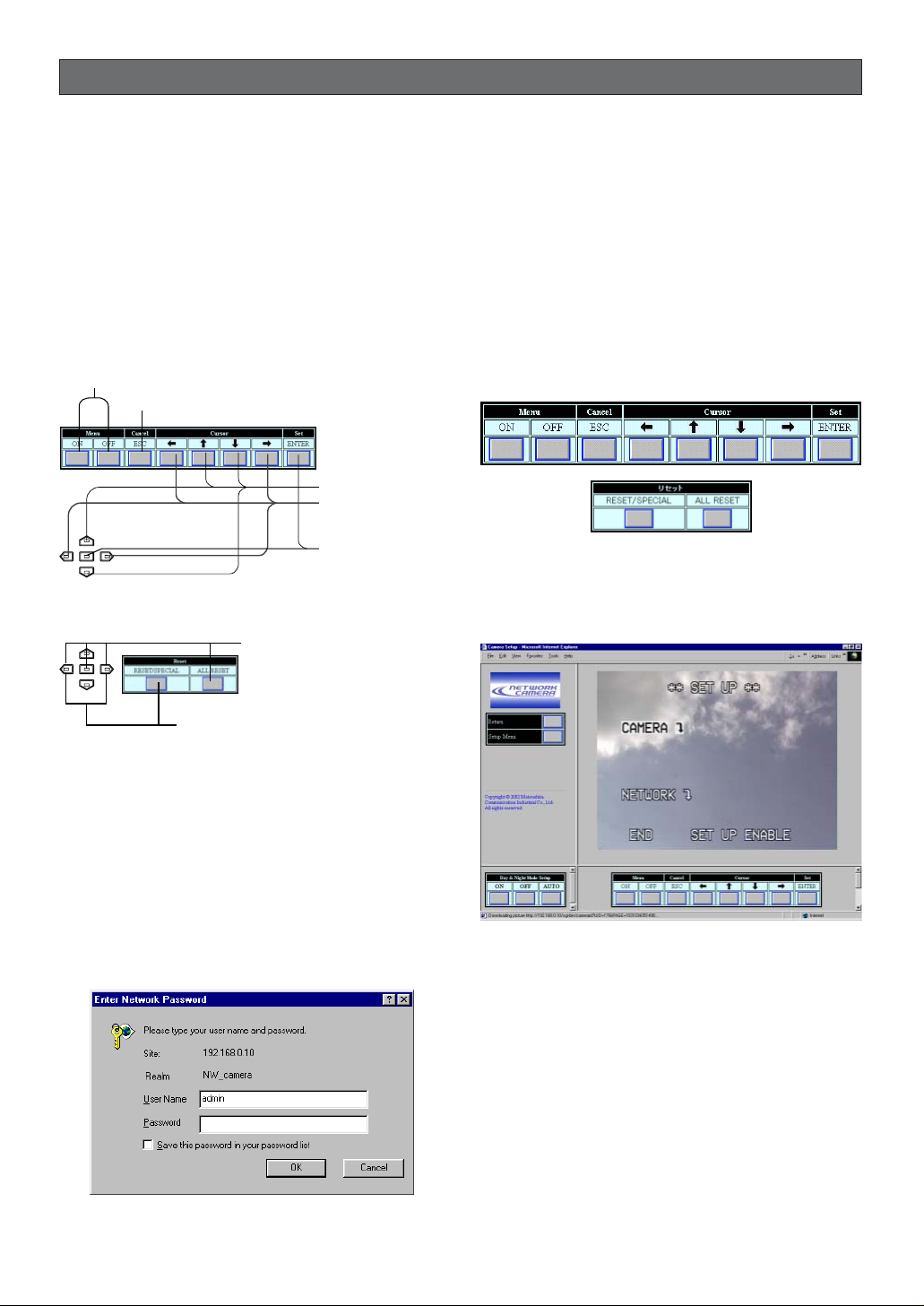
Buttons Used for Setup Menus
Press the buttons on the side panel of the camera, or
click the buttons on the computer display. Each button
is assigned functions in the setup as follows.
Camera Setup Menus
¡From the PC
1. Open the main page of the WV-NP472 camera,
referring to page 12.
Login as a level-1 administrator in the dialog box if
requested.
2. Click Camera Setup button in the left side of the
screen.
Login dialog box will appear.
Note: Confirm the entered IP address when neither
the dialog box nor the main page appears. You
may need to re-enter the IP address.
3. Enter the registered user name and password.
Note: Enter “admin” when you operate the system
very first time, or you have not registered user
names yet. For this time, you need not to enter
the password.
Menu control buttons will appear under the camera
image. Scroll down the bar to display the Reset
buttons.
4. Click the Menu ON button to overlay the **SET
UP** menu on the camera image. The cursor is
highlighted on the window.
5. Move the cursor to SETUP DISABLE if it is displayed, or skip to step 7 if ENABLE is displayed.
6. Click the ENTER button.
DISABLE will change to ENABLE, and the camera
is now ready to be set up.
Note: While DISABLE is displayed, setup opera-
tions are disabled.
Menu ON/OFF button: Opens or closes the setup menu.
ESC button: Returns to the previous menu
(one layer higher) .
Pressing RIGHT, SET,
LEFT or clicking ALL
RESET: Resets all settings
to the factory default.
UP/DOWN button:
Moves up and down
the cursor (pointer).
RIGHT/LEFT button:
Selects parameters,
adjusts some levels.
SET button: Validates
the selection, opens a
detailed menu.
Pressing RIGHT and LEFT, or clicking
RESET: Resets the selected settings to
the factory default.
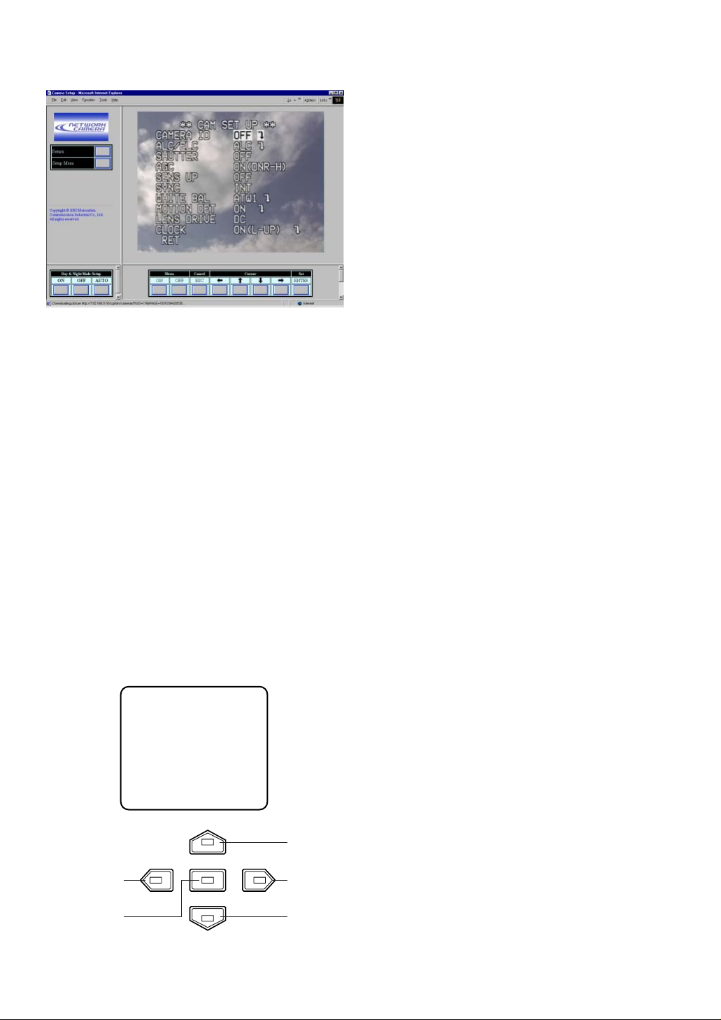
-15-
7. Move the cursor to CAMERA O, and click the
ENTER button. CAM SETUP opens.
Notes:
• Refer to the next page for setup operations.
• Return the menu to ** SET UP *** (step 3
above), then go to step 8.
8. Click the Menu OFF button after finishing the setup
operations.
The changed settings will be stored in the camera,
and the overlaid camera menu will disappear.
Notes:
• Access the camera again on the WWW-browser to validate the settings for PC oriented items
if the browser screen pauses.
• You can exit from the camera setup by clicking
the Return button, though the menu is displayed if the Menu OFF button has not been
clicked yet.
¡From the Camera
1. Hold down the I button for 2 seconds.
The ** SET UP ** will appear, overlaid on the camera image.
2. Move the cursor to SETUP DISABLE.
3. Press the I button.
DISABLE will change to ENABLE, and the camera
is now ready to be set up.
Note: While DISABLE is displayed, setup opera-
tions are disabled.
4. Move the cursor to CAMERA O, and press the I
button. The CAM SETUP opens.
Notes:
• Refer to the next page for setup operations.
• Return the menu to the one in which END is
displayed on the bottom, then go to the next.
5. Move the cursor to END, and press the I button
after finishing the setup.
The changed settings will be stored in the camera,
and the overlaid camera menu will disappear.
Left Button
Set Button
Right
Button
Down
Button
Up
Button
** SET UP **
CAMERA
NETWORK
END SET UP DISABLE
↵
↵
 Loading...