

Page 1
Before attempting to connect or operate this product,
please read these instructions carefully and save this manual for future use.
No model number suffix is shown in this manual.
LOCK
W
V
-N
P
3
04
Network Camera
Installation Guide
Model No. WV-NP304
(Lens is option.)
Page 2
2
The lightning flash with arrowhead symbol, within an equilateral triangle, is intended to alert the
user to the presence of uninsulated "dangerous voltage" within
the product's enclosure that may
be of sufficient magnitude to constitute a risk of electric shock to
persons.
The exclamation point within an
equilateral triangle is intended to
alert the user to the presence of
important operating and maintenance (servicing) instructions in
the literature accompanying the
appliance.
WARNING:
• This apparatus must be earthed.
• To prevent fire or electric shock hazard, do not
expose this apparatus to rain or moisture.
• The apparatus should not be exposed to dripping or splashing and that no objects filled with
liquids, such as vases, should be placed on the
apparatus.
• All work related to the installation of this product should be made by qualified service personnel or system installers.
• The connections should comply with local electrical code.
CAUTION: TO REDUCE THE RISK OF ELECTRIC SHOCK,
DO NOT REMOVE COVER (OR BACK).
NO USER-SERVICEABLE PARTS INSIDE.
REFER SERVICING TO QUALIFIED SERVICE PERSONNEL.
CAUTION
RISK OF ELECTRIC
SHOCK DO NOT OPEN
We declare under our sole responsibility that the product
to which this declaration relates is in conformity with the
standards or other normative documents following the
provisions of Directives 2006/95/EC and 2004/108/EC.
Wij verklaren als enige aansprakelijke, dat het product
waarop deze verklaring betrekking heeft, voldoet aan de
volgende normen of andere normatieve documenten,
overeenkomstig de bepalingen van Richtlijnen
2006/95/EC en 2004/108/EC.
Vi erklærer os eneansvarlige for, at dette produkt, som
denne deklaration omhandler, er i overensstemmelse
med standarder eller andre normative dokumenter i
følge bestemmelserne i direktivene 2006/95/EC og
2004/108/EC.
Vi deklarerar härmed värt fulla ansvar för att den
produkt till vilken denna deklaration hänvisar är i
överensstämmelse med standarddokument, eller andra
normativa dokument som framstölls i direktiv nr.
2006/95/EC och 2004/108/EC.
Ilmoitamme yksinomaisella vastuullamme, että tuote,
jota tämä ilmoitus koskee, noudattaa seuraavia
standardeja tai muita ohjeellisia asiakirjoja, jotka
noudattavat direktiivien 2006/95/EC ja 2004/108/EC
säädöksiä.
Vi erklærer oss alene ansvarlige for at produktet som
denne erklæringen gjelder for, er i overensstemmelse
med følgende normer eller andre normgivende
dokumenter som følger bestemmelsene i direktivene
2006/95/EC og 2004/108/EC.
Page 3

3
Important Safety Instructions
1) Read these instructions.
2) Keep these instructions.
3) Heed all warnings.
4) Follow all instructions.
5) Do not use this apparatus near water.
6) Clean only with dry cloth.
7) Do not block any ventilation openings. Install in accordance with the manufacturer's
instructions.
8) Do not install near any heat sources such as radiators, heat registers, stoves, or other
apparatus (including amplifiers) that produce heat.
9) Do not defeat the safety purpose of the polarized or grounding-type plug. A polarized plug
has two blades with one wider than the other. A grounding type plug has two blades and a
third grounding prong. The wide blade or the third prong are provided for your safety. If the
provided plug does not fit into your outlet, consult an electrician for replacement of the
obsolete outlet.
10) Protect the power cord from being walked on or pinched particularly at plugs, convenience
receptacles, and the point where they exit from the apparatus.
11) Only use attachments/accessories specified by the manufacturer.
12) Use only with the cart, stand, tripod, bracket, or table specified by the manufacturer, or
sold with the apparatus. When a cart is used, use caution when moving the cart/apparatus
combination to avoid injury from tip-over.
13) Unplug this apparatus during lightning storms or when unused for long periods of time.
14) Refer all servicing to qualified service personnel. Servicing is required when the apparatus
has been damaged in any way, such as power-supply cord or plug is damaged, liquid has
been spilled or objects have fallen into the apparatus, the apparatus has been exposed to
rain or moisture, does not operate normally, or has been dropped.
S3125A
Page 4

4
Limitation of Liability
THIS PUBLICATION IS PROVIDED "AS IS"
WITHOUT WARRANTY OF ANY KIND,
EITHER EXPRESS OR IMPLIED, INCLUDING
BUT NOT LIMITED TO, THE IMPLIED WARRANTIES OF MERCHANTABILITY, FITNESS
FOR ANY PARTICULAR PURPOSE, OR
NON-INFRINGEMENT OF THE THIRD
PARTY’S RIGHT.
Disclaimer of Warranty
IN NO EVENT SHALL MATSUSHITA ELECTRIC INDUSTRIAL CO,.LTD. BE LIABLE TO
ANY PARTY OR ANY PERSON, EXCEPT FOR
REPLACEMENT OR REASONABLE MAINTENANCE OF THE PRODUCT, FOR THE
CASES, INCLUDING BUT NOT LIMITED TO
BELOW:
(1) ANY DAMAGE AND LOSS, INCLUDING
WITHOUT LIMITATION, DIRECT OR
INDIRECT, SPECIAL, CONSEQUENTIAL
OR EXEMPLARY, ARISING OUT OF OR
RELATING TO THE PRODUCT;
(2) PERSONAL INJURY OR ANY DAMAGE
CAUSED BY INAPPROPRIATE USE OR
NEGLIGENT OPERATION OF THE USER;
(3) UNAUTHORIZED DISASSEMBLE,
REPAIR OR MODIFICATION OF THE
PRODUCT BY THE USER;
(4) INCONVENIENCE OR ANY LOSS ARIS-
ING WHEN IMAGES ARE NOT DISPLAYED, DUE TO ANY REASON OR
CAUSE INCLUDING ANY FAILURE OR
PROBLEM OF THE PRODUCT;
(5) ANY PROBLEM, CONSEQUENTIAL
INCONVENIENCE, OR LOSS OR DAMAGE, ARISING OUT OF THE SYSTEM
COMBINED BY THE DEVICES OF THIRD
PARTY;
(6) ANY CLAIM OR ACTION FOR DAM-
AGES, BROUGHT BY ANY PERSON OR
ORGANIZATION BEING A PHOTOGENIC SUBJECT, DUE TO VIOLATION
OF PRIVACY WITH THE RESULT OF
THAT SURVEILLANCE-CAMERA'S PICTURE, INCLUDING SAVED DATA, FOR
SOME REASON, BECOMES PUBLIC OR
IS USED FOR THE PURPOSE OTHER
THAN SURVEILLANCE;
(7) LOSS OF REGISTERED DATA CAUSED
BY ANY FAILURE.
THIS PUBLICATION COULD INCLUDE
TECHNICAL INACCURACIES OR TYPOGRAPHICAL ERRORS. CHANGES ARE
ADDED TO THE INFORMATION HEREIN, AT
ANY TIME, FOR THE IMPROVEMENTS OF
THIS PUBLICATION AND/OR THE CORRESPONDING PRODUCT (S).
Page 5

5
Preface
The network camera WV-NP304 is designed to operate using a PC on a network (10BASET/100BASE-TX).
By connecting to a network (LAN) or the Internet, images and audio from the camera can be
monitored on a PC via a network.
Note:
• It is necessary to configure the network settings of the PC and its network environment to
monitor images and audio from the camera on the PC. It is also necessary that a web
browser is installed on the PC.
Features
Introduction of 1.3 mega pixel progressive
scan CCD
The introduction of the progressive scan type
of CCD has achieved excellence in performance for motion images and high resolution.
Adaptive black stretch
This function automatically detects dark and
less viewable portions of a subject and
makes the portions brighter.
Important:
• The use of the adaptive black stretch
function may increase noise at the dark
portions of the subject. The use of this
function may also emphasize the darkness or brightness at the border between
the dark and bright portions compared
with other dark or bright portions.
JPEG/MPEG-4 dual encode
MPEG-4 images can be monitored while
monitoring JPEG images.
Focus assist function equipped
This function informs users of an optimal
focal point at focus adjustment.
No special power supply and cable installation required (Power over Ethernet)
Power can be supplied to the camera and
images/audio transmitted on a single LAN
cable by connecting to PoE-compatible network devices. Special installation of a power
supply for the camera is not required.
Interactive communication with audio is
available
By using the audio output connector and the
microphone in connector, receiving audio
from the camera on a PC and transmitting
audio from the PC to the camera are available.
Motion detection function
When a motion is detected, this product will
take the following actions.
• Outputs alarm signals
• Transfers images to the FTP server
• Notifies by mail
• Saves images on the SD memory card
Page 6

6
Note:
• The motion detector is not a function
dedicated to prevent theft or fire, etc. No
warranty is provided for any damage and
loss resulting in use of this function.
SD memory card slot
Images can be recorded on an optional SD
memory card both automatically (when
images fail to transmit using the FTP periodic
transmission function) and manually. It is
possible to play images saved on the mini
SD memory card using a web browser or to
download images displayed on a web browser.
Note:
• Compatible SD memory card
Performance with this camera has been
checked by using Panasonic’s SD memory cards (64 MB, 128 MB, 256 MB, 512
MB, 1 GB, and 2 GB).
SD High Capacity (SDHC) card is not
compatible with this camera.
Installation on a ceiling or a wall is available
When using an optional mount bracket,
mounting on a ceiling or mounting on a wall
is available.
Page 7

7
About These Operating Instructions
There are 3 sets of operating instructions for the WV-NP304 as follows.
• Installation guide (book, these operating instructions)
• Operating instructions (PDF)
• Setup instructions (PDF)
The "Installation guide" contains descriptions of how to install and connect this camera, and of
how to perform the required network settings.
Refer to the "Operating instructions (PDF)" and the "Setup instructions (PDF)" on the provided
CD-ROM for descriptions of how to perform the camera settings and how to operate this camera. Adobe
®
Reader®is required to read the operating instructions (PDF) and the setup
instructions (PDF).
System Requirements for a PC
CPU Pentium®4 2.4 GHz or faster (A 3.0 GHz CPU or faster CPU is
required when using Microsoft
®
Windows Vista®.)
Memory 512 MB or more (A minimum of 1 GB memory is required when
using Microsoft
®
Windows Vista®.)
Network interface 10/100 Mbps Ethernet port x1
Audio interface Sound card (when using the audio function)
Monitor Resolution: 1 024 x 768 pixels or more
Color: 24-bit True color or better
OS Microsoft
®
Windows Vista®Business (32-bit)
Microsoft
®
Windows®XP Home Edition SP2*
Microsoft
®
Windows®XP Professional SP2*
Web browser Windows
®
Internet Explorer®7.0
* Microsoft
®
Internet Explorer®6.0 SP2 is required when using
Microsoft
®
Windows®XP Home Edition SP2 or Microsoft
®
Windows®XP Professional SP2.
Other CD-ROM drive: It is necessary to read the operating instructions
and use the software on the provided CD-ROM.
DirectX
®
9.0c or later
Adobe
®
Reader®: It is necessary to read the operating instruc-
tions on the provided CD-ROM.
Notes:
• When using a PC that does not meet the above requirements, displaying of images may
become slow or the web browser may become inoperable.
• Audio may not be heard if a sound card is not installed on a PC. Audio may be interrupted
depending on the network environment.
• Refer to "Notes on Vista
®
" (PDF) for further information about system requirements for a PC
and precautions when using Microsoft
®
Windows Vista®.
• Use Microsoft
®
Windows Vista®when operating in an IPv6 network.
Page 8

8
Trademarks and Registered Trademarks
• Microsoft, Windows, Windows Vista,
Internet Explorer, ActiveX and DirectX
are either registered trademarks or trademarks of Microsoft Corporation in the
United States and other countries.
• Intel and Pentium are trademarks or registered trademarks of Intel Corporation or
its subsidiaries in the United States and
other countries.
• Adobe and Reader are either registered
trademarks or trademarks of Adobe
Systems Incorporated in the United
States and/or other countries.
• SD logo is a trademark.
• Other names of companies and products
contained in these operating instructions
may be trademarks or registered trademarks of their respective owners.
Network Security
As you will use this product connected to a network, your attention is called to the following
security risks.
1. Leakage or theft of information through this product
2. Use of this product for illegal operations by persons with malicious intent
3. Interference with or stoppage of this product by persons with malicious intent
It is your responsibility to take precautions such as those described below to protect yourself
against the above network security risks.
• Use this product in a network secured by a firewall, etc.
• If this product is connected to a network that includes PCs, make sure that the system is
not infected by computer viruses or other malicious entities (using a regularly updated antivirus program, anti-spyware program, etc.).
• Protect your network against unauthorized access by restricting users to those who log in
with an authorized user name and password.
• Apply measures such as user authentication to protect your network against leakage or
theft of information, including image data, authentication information (user names and
passwords), alarm mail information, FTP server information and DDNS server information.
• Do not install the camera in locations where the camera or the cables can be destroyed or
damaged by persons with malicious intent.
Page 9

9
CONTENTS
Important Safety Instructions ........................................................................................................3
Limitation of Liability ......................................................................................................................4
Disclaimer of Warranty ..................................................................................................................4
Preface ..........................................................................................................................................5
Features ........................................................................................................................................5
About These Operating Instructions ..............................................................................................7
System Requirements for a PC .....................................................................................................7
Trademarks and Registered Trademarks .....................................................................................8
Network Security ...........................................................................................................................8
Precautions .................................................................................................................................10
Major operating controls and their functions ................................................................................12
Precautions for installation ..........................................................................................................14
Lens mounting .............................................................................................................................16
Adjustment of angular field of view and focus .............................................................................18
Installation ...................................................................................................................................20
Connection ..................................................................................................................................24
Insert/remove an SD memory card .............................................................................................28
Configure the network settings ....................................................................................................29
Troubleshooting ..........................................................................................................................31
Specifications ..............................................................................................................................32
Standard Accessories .................................................................................................................34
Page 10

Cleaning the lens
Use a lens cleaning paper (used to clean
camera lenses or lenses of spectacles).
When using solvent, use an alcohols solvent.
Do not use a thinner or a glass cleaner.
Refresh interval
Image refresh interval may become slow
depending on the network environment, PC
performance, shooting subject, access traffic, etc.
SD memory card
• When insert an SD memory card into the
SD memory card slot, turn the power of
the camera off. Otherwise, it may cause
malfunction or damage data recorded on
the SD memory card.
Refer to page 28 for descriptions of how
to insert/remove an SD memory card.
• When using an unformatted SD memory
card, format it using this camera.
Recorded data on the SD memory card
will be deleted when formatted.
If using an unformatted SD memory card
or using an SD memory card formatted
with other device, the camera may not
work properly or performance deterioration may be caused.
Refer to the setup instructions (PDF) for
descriptions of how to format an SD
memory card.
• It is recommended to use Panasonic’s
SD memory cards (64 MB, 128 MB, 256
MB, 512 MB, 1 GB, and 2 GB) since they
have tested and confirmed full compatibility with this camera.
If another SD memory card is used, the
camera may not work properly or performance deterioration may be caused.
10
Precautions
To continue using with stable performance
Parts of this product may deteriorate and it
may shorten the lifetime of this product when
using in locations subject to high temperatures and high humidity.
(Recommended ambient temperature: 35°C
or below)
Do not expose the product to direct heat
such as from a heater.
Handle this product with care.
Do not strike or shake, as this may damage
the product. It may cause a malfunction.
About the PC monitor
When displaying the same image on the CRT
PC monitor for a long time, the CRT PC monitor may be damaged. It is recommended to
use a screen-saver.
When an error is detected, the camera will
reboot automatically.
This camera will reboot when detecting an
error caused by any reason. The camera will
be inoperable for around 30 seconds after
the reboot just as when the power is turned
on.
Cleaning the camera body
Turn the power off when cleaning the camera.
Otherwise, it may cause injury.
Do not use strong abrasive detergent when
cleaning the camera body.
Otherwise, it may cause discoloration.
When using a chemical cloth for cleaning,
read the caution provided with the chemical
cloth product.
When the dirt is hard to remove
Use a mild detergent and wipe gently.
Then, wipe the detergent completely off with
a dry cloth.
Page 11
11
Code labels
Retain these labels for future reference.
The codes on the label will be requested
when you contact the service station.
It is recommended to paste one of the labels
onto the CD-ROM case.
Discoloration on the CCD color filter
When continuously shooting a bright light
source such as a spotlight, the color filter of
the CCD may have deteriorated and it may
cause discoloration.
Even when changing the fixed shooting
direction after continuously shooting a spotlight for a certain period, the discoloration
may remain.
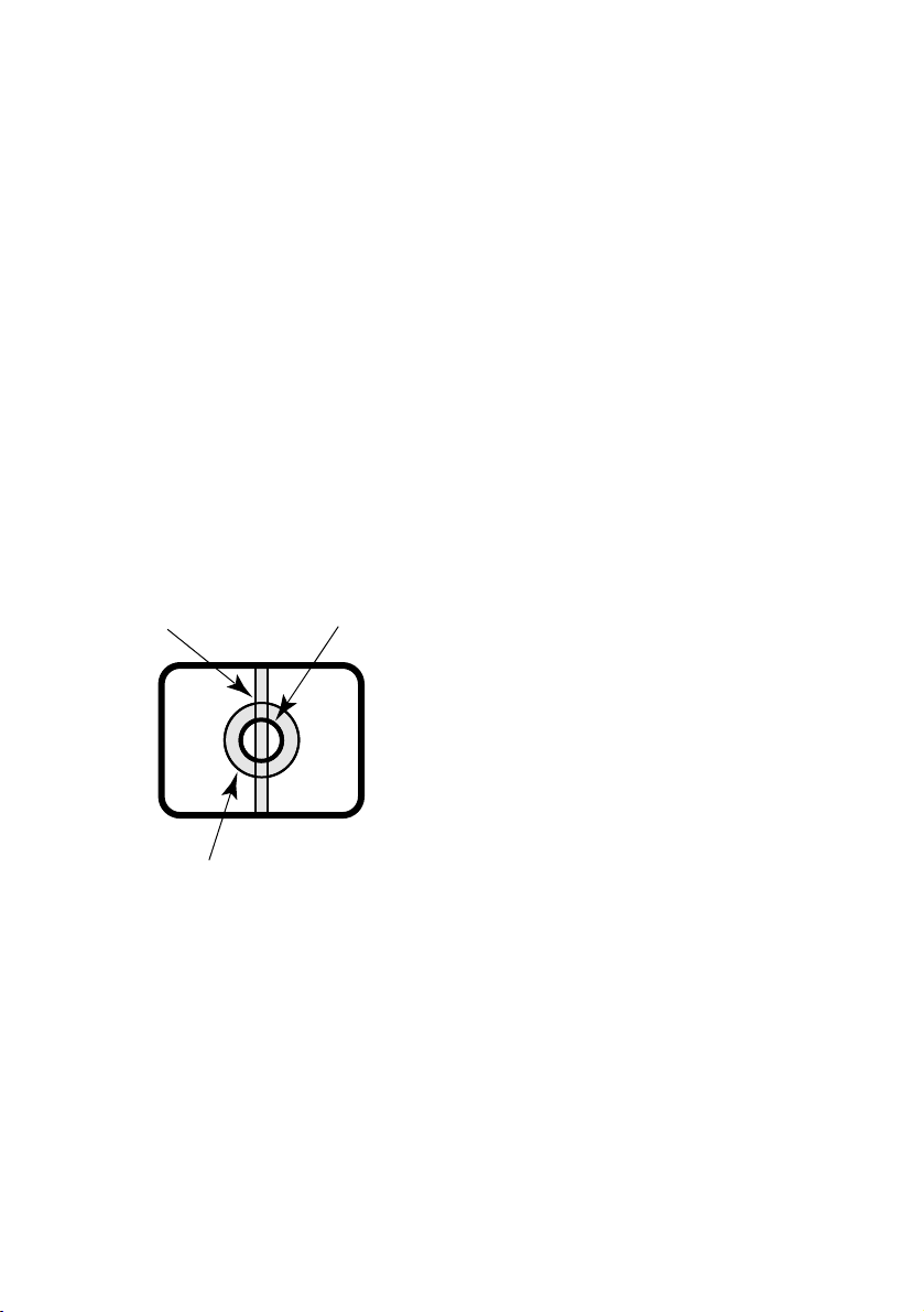
Do not aim the camera at strong light
sources.
A light source such as a spot light causes a
blooming (light bleeding) or a smear (vertical
lines).
Safety wire
The safety wire holder is provided on the top
of the camera. To prevent the camera from
dropping that may cause accidental injury,
attach one end of a safety wire (locally procured) to the safety wire holder of the camera
and the other end to a locally procured safety
wire holder (bracket, etc.) to be installed on
the foundation part of the building.
MPEG-4 Visual patent portfolio license
This product is licensed under the MPEG-4
Visual patent portfolio license for the personal and non-commercial use of consumer for(i)
encoding video in compliance with the
MPEG-4 Visual Standard ("MPEG-4 Video")
and/or(ii) decoding MPEG-4 Video that was
encoded by a consumer engaged in a personal and non-commercial activity and/or
was obtained from a video provider licensed
by MPEG LA to provide MPEG-4 Video. No
license is granted or shall be implied for any
other use. Additional information including
that relating to promotional, internal and commercial uses and licensing may be obtained
from MPEG LA, LLC.
See http://www.mpegla.com.
Smear
Blooming
Bright subject
Page 12

12
Major operating controls and their functions
LOCK
WV-NP304
INITIAL SET
LOCK
WV-NP304
INITIAL SET
w
q
e
r
t
About the [INITIAL SET] button
Turn on the power of the camera while holding down the button, and wait for around 5 seconds
without releasing this button. Wait another 30 seconds after releasing the button. The camera
will restart and the settings including the network settings will be reset to the default.
■ Front/Side View
q Flange-back length adjustment ring
Adjust the flange-back length by rotating
this ring.
Before adjusting the flange-back length,
adjust the lens first. (☞ page 16)
w SD memory card slot cover
Cover the SD memory card slot to protect the SD memory card in the slot.
(☞ page 28)
e Initialization button [INITIAL SET]
Use this button to reset the settings of
the camera to the default settings.
Turn off the power of the camera. Then,
turn on the power of the camera while
holding down this button and wait around
5 seconds without releasing this button.
Wait around 30 seconds after releasing
the button. The camera will restart and
the settings including the network and
the date/time settings will be initialized.
r SD memory card slot
Insert an SD memory card. (☞ page 28)
t Flange-back length fixing screw
Fix the adjusted flange-back length using
this screw. (☞ page 18)
Page 13

13
■ Rear View
q Power indicator [POWER]
Green: This indicator will light green
when the power is on.
w SD memory card error indicator/
Focus assist indicator [SD CARD]
Red: Lights in the following cases.
• When images cannot be stored on
the SD memory card,
• When the focus assist function is
started,
• When BEST FOCUS is displayed.
e Focus assist button [FOCUS ASSIST]
Activates the focus assist function.
(☞ page 18)
r Link indicator [LINK]
Orange: Lights when the communication
with a network is established.
t Network connector
Connect a LAN cable (category 5 or better). (☞ page 25)
y Access indicator [ACT]
Green: Blinks when the camera is
accessed.
u Monitor output connector (for adjust-
ment use only) [MONITOR OUT]
This connector is provided only for
checking the adjustment the angular field
of view or the focus on the video monitor
when installing the camera or when servicing. (☞ page 24)
i External I/O connector [EXT I/O]
Connect an external device to these terminals.(☞ page 25)
o Microphone input connector [MIC IN]
Connect a plug-in power type microphone.
!0 24V AC/12V DC Power cable terminal
Connect to the 24V AC/12V DC power
supply. (☞ page 24)
!1 Audio output connector [AUDIO OUT]
Connect an external powered speaker.
e
w
q
POWER
AUDIO OUT MIC IN
12V IN
24V IN
C B A
!1 !0 oi u
r
t
y
SD
CARD
FOCUS
ASSIST
EXT I/O
1 2 3 4
LINK
ACT
100BASE-TX
MONITOR OUT
100BASE-T/
Page 14

14
Precautions for installation
All work related to the installation of this
product should be made by qualified service personnel or system installers.
Use this product for indoor use only.
Do not expose this product to direct sunlight
for hours and do not install the product near
a heater or an air conditioner. Otherwise, it
may cause deterioration, discoloration and
malfunction. Keep this product away from
water.
Avoid installing in the following locations.
• Locations where it may get wet from rain
or water splash
• Locations where a chemical agent is
used such as a swimming pool
• Locations subject to steam and oil smoke
such as a kitchen
• Locations near flammable gas or vapor
• Locations where radiation or x-ray emissions are produced
• Locations where it may be damaged by
briny air such as seashores
• Locations where the temperature is not
between –10°C - +50°C
• Locations subject to vibrations (This
product is not designed for on-vehicle
use.)
• Locations subject to condensation as the
result of severe changes in temperature
Be sure to remove this product if it is not
in use.
Before starting installation
• Use the camera mount bracket shown on
page 23 to mount the camera.
• When installing the camera and the camera mount bracket on a ceiling/wall, use
the screws listed on page 22. Screws are
not provided with this product. Prepare
them after considering the total weight,
the material and strength of the area
where the camera is to be installed.
• The installing place shall be sufficiently
reinforced and anchors/screws to be
used shall be strong enough for the
installation.
• Do not install the camera on a plaster
board or on a wood board since they
don’t have enough strength for installation.
When tightening fixing screws
• Firmly tighten screws that are suited to fix
with the material and strength of the area
where the camera is to be installed.
• Do not use a powered screw driver.
Otherwise, it may damage the camera.
• Tighten screws firmly. After tightening
screws, check with eyes if the camera is
fixed firmly.
Safety wire
When using a locally procured safety wire to
prevent the camera from dropping, determine the installing place after considering
possibilities of injury that may be caused by
the camera mount bracket if it is damaged.
When using a safety wire, adjust the length to
stretch the wire with tension.
Adjustment of the tilting angle
Before adjusting the tilting angle of the camera, make sure that the screws of the camera
mount bracket are loosened. Failure to do so
may damage both the camera and the camera mount bracket. Tighten the screws firmly
after adjusting the tilting angle of the camera.
Radio disturbance
When this product is used near a TV/radio
antenna, or a strong electric field or magnetic
field (such as near a motor, a transformer or
power lines), images may be distorted and
noise may be caused.
PoE (Power over Ethernet)
Use a PoE hub/device that is compliant with
IEEE802.3af standard.
Page 15

15
Router
When connecting this product to the Internet,
use a broadband router with the port forwarding function (NAT, IP masquerade).
Refer to the setup instructions (PDF) for how
further information about the port forwarding
function.
Page 16

16
Mount the lens by rotating it clockwise slowly. Then, connect the lens cable to the ALC lens
connector of the camera.
Optional lens
Lens type Model no.
ALC lens for 1/3-inch type CCD cameras WV-LZA62/2
2x varifocal (high resolution)
Other lenses for 1/3 inch CCD cameras can be mounted on this camera. However, high resolution scanning of this camera may not be fully used for scanning of "1 280 x 960".It is recommended to use a dedicated high-resolution lens when shooting a dark subject with the aperture
opened.
How to use a varifocal lens
The following are descriptions of how to adjust a 2x varifocal
lens. Method of adjustment may be different depending on
the lens in use. Refer to the operating instructions of the lens
in use for further information.
1. Loosen the zoom lock screw and rotate to the "T" end.
2. Set the focus ring to near the "F" end.
3. Focus on a subject which is located around 10 m away
or further to adjust the flange-back length using flangeback adjustment ring.
Important:
• Check if it is possible to focus on a subject which is located around 1.2 m away by rotating
the focus ring while setting the zoom lock screw to the "W" end.
Lens mounting
Flange-back adjustment ring
Zoom lock screw
T
W
Within ø20 mm
ALC lens connector
Focus ring
CS-mount: Less than 8 mm
Zoom lock screw
T
W
q
Focus ring
N
w
F
Page 17

17
4. Loosen the zoom lock screw, and then move the angular field of
view between "TELE" and "WIDE". Tighten the zoom lock screw
after moving the angular field of view.
5. Press the focus assist button, and then rotate the focus ring to
focus on a subject appropriately.
Important:
• To change the angular field of view by moving the zoom ring, also move the focus ring to
adjust the focus coarsely.
How to use a fixed-focus lens
When using a fixed-focus lens featured the focus adjustment, adjust the flange-back length
after setting the lens focus to the "FAR" end.
Before adjusting the flange-back length, make sure that the flange-back ring fixing screw is
loosened. Tighten the fixing screw after adjusting the flange-back length.
Recommended tightening torque: 0.05 N·m
Important:
• Do not tighten the flange-back ring fixing screw with excessive force. It may strip threads
of the screw and may result in out of focus subjects.
T
N
W
r
t
F
Page 18

18
Angular field of view and focus can be adjusted coarsely according to the distance between
the camera and a subject. Adjust angular field of view and focus while determining the shooting direction.
z Loosen the zoom lock screw, and then adjust the angular field of view by rotating the zoom
lock screw. Move the focus coarsely by rotating the focus ring.
x Tighten the zoom lock screw.
c Press the focus assist button.
→ The "FOCUS ADJUSTMENT" screen appears.
The focus assist function provides optimal adjustment.
v Move the focus ring to near the focal point to automatically register the optimal focal point
as the "PEAK HOLD" value (higher value for closer to the focal point).
b Move the focus ring to display the value of the current focus state at "INDICATOR". Adjust
the focus ring to bring the value of "INDICATOR" close to the value of "PEAK HOLD".
n When the focal point is obtained, highlighted "BEST FOCUS" appears at the lower right
position.
m Press the focus assist button again to exit from the "FOCUS ADJUSTMENT" screen (or wait
for approx. 3 minutes to automatically terminate).
Adjustment of angular field of view and focus
FOCUS ADJUSTMENT
LOW HIGH
.......|............
INDICATOR 775 BEST
PEAK HOLD 780 FOCUS
↑
Zoom lock screw
T
W
Focus ring
Loosen Tighten
Page 19

19
Note:
• If the angular field changed during adjustment, press the focus assist button to exit from
the "FOCUS ADJUSTMENT" screen once (because change in the angular field causes
change in the values of "PEAK HOLD" and "INDICATOR"). After adjustment of angular field,
conduct the procedure from step 3.
Important:
• If a subject is applicable to the following, press the focus assist button again to exit from
the "FOCUS ADJUSTMENT" screen or obtain an optimal focal point while viewing the
image.
• Frequently moving subject
• Subject with remarkable illuminance change
• Subject with low illuminance
• Too bright or reflective subject
• Subject through a window
• Place where the lens easily becomes dirty
• Subject with less contrast such as white wall
• Subject with remarkable depth
• Subject with heavy flicker
• Subject with horizontally parallel lines such as a shutter
Page 20

20
Attach a safety wire
The following is a safety wire attachment example. Procure an appropriate safety wire kit
according to the installing place.
Refer to the operating instructions of the safety wire kit in use together with this installation
guide when attaching a safety wire.
Important:
• To prevent the camera from dropping that may cause accidental injury, attach a safety
wire between the camera and the installing place. Contact your dealer for attachment of a
safety wire.
When installing on a ceiling
<Required camera mount bracket and safety wire kit>
• Camera mount bracket: WV-7010A
• Safety wire kit: WV-Q141
z Detach the tripod mount base from the camera.
x Fix the tripod mount base and the safety
wire attachment bracket for ceiling
mount (provided) using the fixing screw.
Use the removed screw (used to fix the
tripod mount base).
When a screw other than the removed
screw (with a different height) is used, it
may result in drop or damage of the
camera.
Recommended tightening torque: 0.39
N·m
c Attach the two safety wires to the safety wire attachment holes (front/rear).
q Pass the loop end of the safety wire through the safety wire attachment hole.
w Hook the loop end of the safety wire on the safety wire hook.
Installation
Tripod mount base
Safety wire
attachment
bracket for ceiling
mount (provided)
Safety wire
attachment hole
(front)
Fixing screw
T
Safety wire
attachment hole
(rear)
Safety wire attachment hole
Safety wire
Safety wire hook
Page 21

21
x Attach the safety wire to the safety wire attachment hole.
q Pass the loop end of the safety wire through the safety wire attachment hole.
w Hook the loop end of the safety wire on the safety wire hook.
When installing on a wall
<Required camera mount bracket and safety wire kit>
• Camera mount bracket: WV-831
• Safety wire kit: WV-Q140
z Attach the safety wire attachment bracket for wall mounting (provided) to the screw hole
for the camera mount bracket using the fixing screw (provided).
Important:
• Use the provided screw to attach the
safety wire attachment bracket for wall
mounting.
When a screw other than the removed
screw (with a different height) is used, it
may result in drop or damage of the
camera.
Recommended tightening torque: 0.39
N·m
* Do not attach the
safety wire here.
Screw hole for the
camera mount
bracket
Safety wire attachment hole
Safety wire
Safety wire attachment hole
Safety wire hook
Fixing screw (provided)
Safety wire
attachment bracket
for wall mount
(provided)
T
W
Page 22

22
Camera mounting
Mount the camera onto an optional camera mount bracket and attach the safety wire.
Important:
• Make sure that the installing place is strong enough to support the total weight of the camera and the camera mount bracket.
• Installing the camera mount bracket on the foundation part of the building or equivalent
strong part.
• Do not use wood screws to fix the camera mount bracket (option) since they are not strong
enough to support the weight of the camera and the bracket.
z Fix an optional camera mount bracket onto the desired place and mount the camera on it.
Use appropriate screws for the ceiling/wall material to secure an optional camera mount
bracket. Method of installation may be different depending on the material of the place
where the camera mount bracket is to be installed.
• When installing on steel: Fix with bolts and nuts (M6 or M8)
• When installing on concrete: Fix with anchor bolts (M6 or M8)
• The following are the requirements of the camera mount bracket installation:
Important:
• When installing the camera mount
bracket on wall, installation height of the
camera mount bracket shall be as indicated in the following illustrations.
Installing place
On ceiling
On wall
Appropriate cam-
era mount bracket
WV-7010A
Recommended
screw
M6 or M8
Number of
screw
3 pcs.
Pull-out capacity
of a single screw
196 N
WV-831 M8 4 pcs. 921 N
More than 270 cm
Floor
Page 23

23
x Hook the safety wire attachment hook on the safety wire attachment plate (provided with
the safety wire kit) or the safety wire attachment bracket (provided with the safety wire kit)
that is fixed on the foundation part of the building or equivalent strong part.
Important:
• The safety wire shall be attached with tension applied.
<When installing on ceiling>
<When installing on wall>
[Installation example]
[Installation example]
Foundation part of the building or
equivalent strong part
Safety wire
Safety wire attachment plate
(provided with the safety wire kit)
Safety wire hook
Camera mount bracket
Safety wire hook
Safety wire
Safety wire attachment bracket
(provided with the safety wire kit)
Safety wire
Page 24

24
Before starting the connection, make sure that the power of the devices to be connected such
as the camera and a PC are off or the power cords of the devices are disconnected.
Before starting the connection, prepare the required devices and cables.
z Connect an RCA plug to the monitor out con-
nector provided on the rear only for adjustment of the angular field of view on the video
monitor.
Important:
• The monitor out connector is provided only
for checking the adjustment of the angular
field of view on the video monitor when
installing the camera or when servicing.
It is not provided for recording/ monitoring use.
Connection
x Connect to the power source.
Important:
• 24V AC/12 V DC power supply shall be insulated
against 220 V - 240 V AC.
• When connecting to 24 V AC/12 V DC power
source
q Loosen the screw of the provided power cord
plug.
w Insert the power cord of an optional AC adapter
to the power cord plug.
When using 24 V AC/12 V DC power supply,
remove 3 mm - 7 mm of the outer jacket of the
power cord from a power supply and twist the
core of the power cord to prevent a short circuit.
Specification of cord (wire): AWG #22 - #28 sin-
gle core, twisted
<Ratings>
AC24 V DC12 V
AN @(GND)
B GND NC
CL !
* Make sure that the power cord plug
is inserted to the power cord terminal firmly.
* Make sure that the exposed core wires are
completely hidden after inserting the power
cord.
e Tighten the screws to fix the inserted power
cord.
r Connect the power cord plug to the 24 V
AC/12 V DC power cord terminal on the rear
of the camera.
Caution:
ONLY CONNECT THIS TO 24 V AC OR 12 V DC CLASS 2 POWER SUPPLY.
POWER
AUDIO OUT MIC IN
12V IN
24V IN
C B A
FOCUS
ASSIST
SD
CARD
POWER
AUDIO OUT MIC IN
12V IN
24V IN
C B A
EXT I/O
1 2 3 4
SD
CARD
LINK
FOCUS
ASSIST
100BASE-T/
100BASE-TX
ACT
Connect to the video
monitor, etc.
MONITOR OUT
100BASE-T/
100BASE-TX
LINK
ACT
MONITOR OUT
EXT I/O
1 2 3 4
To power source
(24 V AC/12 V DC)
@
!
C
B
A
Approx. 3 mm - 7 mm
Power cord plug (provided)
Page 25

25
b Connect an external device to the EXT connector.
Remove 9 mm - 10 mm of the outer jacket of the cable from the
external device and twist the core of the cable to prevent a short circuit.
Specification of cord (wire): AWG #22 - #28 single core, twisted
* Make sure that the exposed core wires are completely hidden
after inserting the cable.
Important:
• Do not connect 2 wires or more directly to a terminal. When it is necessary to connect 2 wires or
more, use a splitter.
• Connect an external device with verifying that the
ratings are within the specification below.
<Ratings>
q GND
w AUX OUT
Output specification: Open collector output (Maximum applied voltage: 20 V DC)
Open: 4 - 5 V DC by internal pull-up
Close: Output voltage of 1 V DC or less (50 mA or less)
e ALARM OUT
Same as AUX OUT
r ALARM IN
Input specification: Non-voltage make contact (4 - 5 V DC internal pull-up)
OFF: Open or 4 - 5 V DC
ON: Make contact with GND (drive current: 1 mA or more)
• When using PoE (Power over Ethernet: IEEE802.3af compliant)
Connect a LAN cable (category 5 or better) between a PoE device (such as a PoE hub) and
the network connector of the camera.
Important:
• Use all of 4 pairs (8 pins) of the LAN cable.
• Maximum length of an Ethernet cable that can be connected is 100 m.
• Make sure that the PoE device in use is compliant with IEEE802.3af standard.
• When connecting both the 12 V DC power supply and the PoE device for power supply,
PoE will be used for power supply.
• When disconnecting the LAN cable once, connect the cable again after 2 seconds or
more from the disconnection. When the cable is connected before 2 seconds passed, the
power may not be supplied from the PoE device.
• Refer to the provided slip (Recommended network devices for PoE (IEEE802.3af compliant) connection with the WV-NP304) for applicable PoE devices.
v Connect a LAN cable (category 5 or better)
to the network connector on the rear.
POWER
AUDIO OUT MIC IN
12V IN
24V IN
C B A
100BASE-T/
FOCUS
100BASE-TX
LINK
ACT
ASSIST
SD
CARD
MONITOR OUT
EXT I/O
1 2 3 4
q GND
w AUX OUT
(AUX output terminal)
1 2 3 4
r ALARM IN (Alarm input terminal)
e ALARM OUT
(Alarm output terminal)
Ethernet cable
Cut
Approx. 9 mm - 10 mm
Page 26

26
Connection example
When connecting with a PC directly
<Required cables>
Ethernet cable (category 5 or better, cross)
When connecting to a network using a PoE device (hub)
<Required hardware>
PoE device (hub)
<Required cables>
Ethernet cable (category 5 or better, straight)
To 12 V DC or 24 V AC
power supply
Video monitor
(only for adjustment)
Ethernet switching hub or router/
PoE compatible hub
PC
Ethernet cable
(category 5 or better, cross)
Ethernet cable
(category 5 or better, straight)
Ethernet cable
(category 5 or better, straight)
Video monitor
(only for adjustment)
Ethernet cable
(category 5 or better, straight)
PC
Page 27

27
Important
• The monitor out connector is provided only for checking the adjustment of the angular field
of view on the video monitor when installing the camera or when servicing. It is not provided for recording/ monitoring use.
• Use a switching hub or a router which is compliant with 10BASE-T/100BASE-TX.
• Power supply is required for each network camera. When using a PoE device (hub), 12 V
DC power supply is unnecessary. When using a PoE device (hub), 12 V DC power supply
is unnecessary.
Page 28

28
T
T
INITIAL SET
SD memory card slot
T
T
INITIAL SET
SD memory card slot
Important:
• Before inserting the SD memory card, turn off the power of the camera first.
How to insert an SD memory card
Important:
• Make sure that the SD memory card is inserted with the reverse side up.
Insert/remove an SD memory card
q Loosen the lock screw of
the SD memory card slot
cover.
w Open the SD memory
card slot cover.
e Insert the SD memory
card into the SD card
memory slot.
r Tighten the screw to close the SD memory card slot cover firmly.
Recommended tightening torque: 0.19 N·m
t Select "Use" for "SD memory card" on the [SD memory card] tab of "Basic" on the setup
menu.(☞ Setup instructions (PDF))
How to remove the SD memory card
Important:
• Before removing the SD memory card, select "Not use" for "SD memory card" on the [SD
memory card] tab of "Basic" on the setup menu first. After configuring the setting above,
turn off the power of the camera and then remove the SD memory card. (☞ Setup instructions (PDF))
q Loosen the lock screw
of the SD memory
card slot cover.
w Open the SD memory
card slot cover.
r Tighten the screw to close the SD memory card slot cover firmly.
Recommended tightening torque: 0.19 N·m
e Release the locked SD memory
card by pushing the card and
then pull the SD memory card
from the slot.
Page 29

29
Install the software
Before installing the software, read the readme file on the provided CD-ROM first.
Software included on the provided CD-ROM
• Panasonic IP setting software
Configure the network settings of the camera. Refer to the following for further information.
• Viewer software "Network Camera View3"
It is necessary to install the viewer software "Network Camera View3" to display images on
a PC. Double-click the "nwcv3setup.exe" icon on the provided CD-ROM and follow the
instructions of the displayed install wizard to install the viewer software "Network Camera
View3".
Configure the network settings of the camera using the
Panasonic IP setting software
It is possible to configure the network settings of the camera using the IP setting software on
the provided CD-ROM.
When using multiple cameras, it is necessary to configure the network settings of each camera
independently.
If the Panasonic IP setting software does not work, configure the network settings of the camera and the PC individually on the "Network" page of the setup menu. Refer to the setup
instructions (PDF) for further information.
Important:
• When using Windows® XP SP2, the "Windows Security Alert" window may be displayed
when starting the IP setting software.
In this case, click the "Unblock" button on the displayed "Windows Security Alert" window.
• If Windows Vista® is used, the password of the administrator account may be required
after startup of the Panasonic IP setting software. In such a case, disable "User Account
Control" from Control Panel.
• For the security enhancement, the MAC address/IP address of the camera to be configured will not be displayed when around 20 minutes have passed after turning on the power
of the camera.
• The Panasonic IP setting software is inoperable from other subnets via the same router.
• It is impossible to display and configure this camera when using an old version (ver. 2.xx)
of the Panasonic IP setting software.
Configure the network settings
Page 30

30
z Start the Panasonic IP setting software.
x Click the [IP setting] button after selecting
the MAC address/IP address of the camera
to be configured.
Note:
• When using a DHCP server, the IP address
assigned to the camera can be displayed by
clicking the [Refresh] button of the IP setting
software.
c Complete each network setup item and click
the [Apply] button.
Note:
• When using a DHCP server, it is possible to
set "DNS" to "Auto".
Important:
• It may take around 30 seconds to completely upload the settings of the camera after clicking the [Apply] button. The settings may be invalidated when the power supply from the
AC adapter is cut or when the LAN cable is disconnected before completing the upload.
In this case, perform the settings again.
• When using a firewall (including software), allow access to all UDP ports.
Page 31

31
Before asking for repairs, check the symptoms on the following table.
Contact your dealer if a problem cannot be solved even after checking and trying the solution
or if the problem is not described below.
Troubleshooting
Symptom
Cause/solution
Reference
pages
The power cannot be
turned on.
When using AC/DC power supply
• Is 24 V AC/12 V DC power supply
connected to the power cord terminal?
→ Confirm the cable is firmly con-
nected.
When using a PoE device for power
supply
• Are the PoE device and the network
connector on the rear of the camera connected using a LAN cable
(4-pair)?
→ Confirm the cable is firmly con-
nected.
• Depending on the PoE device, the
power supply will stop when the
demanded power exceeds its total
power limit for all PoE ports.
→ Refer to the operating instruc-
tions of the PoE device in use.
24 - 25
Page 32

32
Specifications
General specification
Power source 24V AC, 50 Hz, 12 V DC, PoE (IEEE802.3af compliant)
Power consumption 12 V DC: 530 mA, PoE: 6.4 W (Class 2 device)
24V AC, 50 Hz: 5.2 W
Ambient temperature –10 °C - +50 °C
Ambient humidity 90 % or less
Monitor output
(only for adjustment) VBS: 1.0 V [P-P]/75 Ω, composite, RCA jack (monaural)
External I/O terminals ALARM IN, ALARM OUT, AUX OUT (x1 each)
Microphone input ø3.5 mm mini-jack (applicable microphone: plug-in-power
type)
Supply voltage: 2.5 V ±0.5 V
Input impedance: 3 kΩ ±10 %
Audio output ø3.5 mm stereo mini-jack (line-level, monaural output)
Dimensions 72 (W) mm x 68 (H) mm x 158 (D) mm (excluding connec-
tors/terminals)
Weight Approx. 470 g
Camera
Image sensor 1/3-inch type, interline transfer CCD
Effective pixels 1 296 (H) x 976 (V)
Scanning area 4.86 mm (H) x 3.65 mm (V)
Scanning system Progressive
Minimum illumination Color: 1.5 lx, Simplified black and white: 0.9 lx
(F 1.4, WIDE end, automatic slow shutter: Off, AGC: High)
AGC On (Low)/On (Mid)/On (High)/Off
Light control mode Outdoor scene/Indoor scene/ELC, (BLC On/Off selectable)
Automatic slow shutter Off, Max. 2/30s, Max. 4/30s, Max. 6/30s, Max. 10/30s,
Max. 16/30s
Adaptive black stretch On/Off
White balance ATW1/ATW2/AWC
Simple black/white mode Off/Auto
VMD alarm On/Off, 4 areas available
ALC lens drive DC drive
Privacy zone On/Off (up to 8 zones available)
Lens mount CS-mount
Optional lens WV-LZA62/2
Page 33

33
Network
Network 10BASE-T/100BASE-TX, RJ45 connector
Resolution 1 280 x 960/VGA (640 x 480)/QVGA (320 x 240)
Image compression method
MPEG-4 MPEG-4 Image quality: LOW/NORMAL/FINE
Transmission type: UNICAST/MULTICAST
JPEG JPEG Image quality: 0 SUPER FINE/1 FINE/2/3/4/5 NOR-
MAL/6/7/8/9 LOW (10 steps: 0-9)
Transmission type: PULL/PUSH
Refresh interval 0.1 fps - 30 fps (Frame rate of JPEG display will be limited
when displaying JPEG and MPEG-4 simultaneously.)
Audio compression method G.726 (ADPCM) 32 kbps/16 kbps
Bandwidth Control 64 kbps/128 kbps/256 kbps/512 kbps/1 024 kbps/
2 048 kbps/4 096 kbps/Unlimited
Protocol IPv4 TCP/IP, UDP/IP, HTTP, RTP, FTP, SMTP, DHCP, DNS, DDNS,
NTP, SNMP
IPv6 TCP/IP, UDP/IP, HTTP, RTP, FTP, SMTP, DNS, NTP, SNMP
OS Microsoft
®
Windows Vista®Business (32-bit)*1 *2,
Microsoft
®
Windows®XP Home Edition SP2,
Microsoft
®
Windows®XP Professional SP2
Web browser Windows
®
Internet Explorer®7.0
* Microsoft
®
Internet Explorer®6.0 SP2 is required when
using Microsoft
®
Windows®XP Home Edition SP2 or
Microsoft
®
Windows®XP Professional SP2.
Maximum access concurrent
number 16 (Depends on network conditions)
FTP client Alarm FTP image transmission, FTP periodic transmission
(When the FTP periodic transmission is failed, backup on an
optional SD memory card is available.)
Multi-screen Images from 16 cameras can be displayed simultaneously.
SD memory card (optional) Manufactured by Panasonic (Performance with this camera
has been checked.)
Capacity: 64 MB, 128 MB, 256 MB, 512 MB, 1 GB, 2 GB
* SD High Capacity (SDHC) card is not compatible with this
camera.
*1: Refer to "Notes on Vista
®
" (PDF) for further information about system requirements for a PC
and precautions when using Microsoft
®
Windows Vista®.
*2: Use Microsoft
®
Windows Vista®when using in an IPv6 network.
Page 34

34
Standard Accessories
CD-ROM* ......................................................................................................... 1 pc.
Installation Guide (this book) ........................................................................... 1 pc.
Code Label ....................................................................................................... 1 pc.
The following is for the installation.
Power cord plug ............................................................................................... 1 pc.
Safety wire attachment bracket for wall mount ................................................ 1 pc.
Safety wire attachment bracket for ceiling mount ............................................ 1 pc.
Screw (M2.5 x 8) ........................................................... 2 pcs. (incl. a spare screw)
* The CD-ROM contains the operating instructions (PDFs) and the software.
Page 35

35
Page 36

Matsushita Electric Industrial Co., Ltd.
Osaka, Japan
http://panasonic.net
Importer's name and address to follow EU rules:
Panasonic Testing Centre
Panasonic Services Europe GmbH
Winsbergring 15, 22525 Hamburg F.R.Germany
© 2008 Matsushita Electric Industrial Co., Ltd. All Rights Reserved.
Ns0608-0 3TR005494AZA Printed in China
Information on Disposal for Users of Waste Electrical & Electronic Equipment (private
households)
This symbol on the products and/or accompanying documents means that used electrical
and electronic products should not be mixed with general household waste.
For proper treatment, recovery and recycling, please take these products to designated collection points, where they will be accepted on a free of charge basis. Alternatively, in some
countries you may be able to return your products to your local retailer upon the purchase of
an equivalent new product.
Disposing of this product correctly will help to save valuable resources and prevent any
potential negative effects on human health and the environment which could otherwise arise
from inappropriate waste handling. Please contact your local authority for further details of your nearest designated collection point.
Penalties may be applicable for incorrect disposal of this waste, in accordance with national legislation.
For business users in the European Union
If you wish to discard electrical and electronic equipment, please contact your dealer or supplier for further
information.
Information on Disposal in other Countries outside the European Union
This symbol is only valid in the European Union.
If you wish to discard this product, please contact your local authorities or dealer and ask for the correct
method of disposal.
 Loading...