

Page 1

Network camera
Operating Instructions
Model Nos. WV-NP1000
WV-NP1004
P
U
S
H
T
O LOC
K
/E
JE
C
T
WV-NP1004
The illustration above is of the WV-NP1004.
Before attempting to connect or operate this product,
please read these instructions carefully and save this manual for future use.
(Lens is option.)
The model numbers in these Operating Instructions are given without suffix.
Page 2

Contents
Preface ............................................................................................................................ 3
About these operating instructions .............................................................................. 3
Trademarks and registered trademarks ...................................................................... 3
Monitoring Images on a PC ............................................................................................. 4
Monitor images from a single camera ......................................................................... 4
Monitor images from multiple cameras ....................................................................... 9
Action at an Alarm Occurrence ....................................................................................... 10
Transmit Images onto an FTP Server ............................................................................. 11
Transmit an alarm image at an alarm occurrence (Alarm image FTP transmission) ... 11
Transmit images at a designated interval or period (FTP periodic transmission) ....... 11
Save images on the SD memory card when failed to transmit images by the
FTP periodic transmission function ............................................................................. 12
About the Network Security of the Camera ..................................................................... 14
Equipped security functions ........................................................................................ 14
Display the Setup Menu and Configure the Settings of the Camera Using a PC .............15
How to display the setup menu ................................................................................... 15
How to operate the setup menu .................................................................................. 16
Configure the basic settings of the camera [Basic setup] ........................................... 19
Configure the settings relating to images and audio [Camera setup] ......................... 23
Configures the multi-screen settings [Multi-screen setup] .......................................... 27
Configure the alarm settings [Alarm setup] ................................................................. 28
Configure the settings relating to Panasonic alarm protocol
[Panasonic alarm protocol setup] ................................................................................ 34
Configure the settings relating to the authentication [Authentication setup] ............... 35
Configure the settings of the servers [Server setup] ................................................... 37
Configuring the network settings [Network setup] ....................................................... 39
Maintenance of the camera [Maintenance] ................................................................. 46
Configure the Camera Settings such as Image Quality, Brightness, etc. ........................ 49
Configure the settings relating to the camera operations [CAMERA SETUP] ............ 49
Configure the settings relating to the flange-back [BACK-FOCUS] ............................ 52
Configure the settings on the "SPECIAL SETUP" page [SPECIAL SETUP] .............. 54
Configure the network settings [NETWORK] .............................................................. 55
Configure the detailed settings .................................................................................... 56
About the Displayed System Log .................................................................................... 63
Troubleshooting ............................................................................................................... 65
2
Page 3

Preface
About these operating instructions
There are 2 sets of operating instructions for the WV-NP1000/WV-NP1004 as follows.
• Operating Instructions (book)
• Operating Instructions (PDF, these operating instructions)
These operating instructions contain descriptions of how to operate this product using a PC via a network and of
how to configure the settings. These operating instructions also contain descriptions of how to display the SETUP
menu on the video monitor connected to the VIDEO OUT connector of the camera and of how to configure the settings on the SETUP menu using the operation buttons on the side of the camera.
Refer to the operating instructions (book) for descriptions of how to install this product and of how to connect to a
network.
Adobe®Reader is required to read these operating instructions (PDF). When the Adobe®Reader is not installed on
the PC, download the latest Adobe®Reader from the Adobe web site and install it.
Note:
The images of the setup menus in these operating instructions are of the WV-NP1004.
Trademarks and registered trademarks
• Adobe, Adobe logos, and Acrobat are registered trademarks of Adobe Systems Incorporated in the U.S. and/ or
other countries.
• SD logo is a trademark.
• Other names of companies and products contained in these operating instructions may be trademarks or regis-
tered trademarks of their respective owners.
3
Page 4

Monitoring Images on a PC
The following are descriptions of how to monitor images from the camera on a PC.
Monitor images from a single camera
Step 1
Start up the web browser.
Step 2
Enter the IP address designated using the Panasonic IP
setup software in the address box of the browser.
(Example: http://192.168.0.10)
Important:
• When the HTTP port number is changed from "80",
enter the IP address of the camera after "http://", for
example "http://192.168.0.11".
• Configure the web browser to not use the proxy
server. Refer to the network administrator when
using the proxy server.
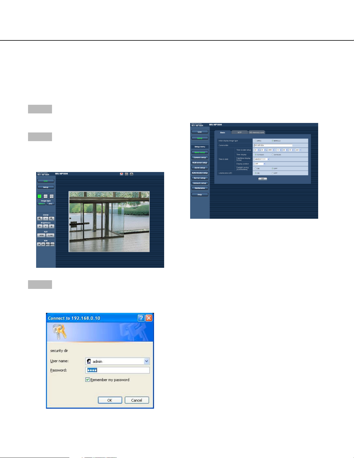
Step 3
Press the [Enter] key on the keyboard.
→ Live images will be displayed.
Notes:
• When "ON" is selected for "User Authentication", the
authentication window will be displayed before displaying live images for the user name and password
entries. The default user name and password are as
follows.
User Name: admin
Password: 12345
To enhance the security, change the password for
the user "admin". It is recommended to change this
password periodically.
• When "Unicast" is selected for "Transmission type"
(☞ page 24), up to 8 users can access the camera
concurrently. When 8 users have been concurrently
accessing already, the access limit message will be
displayed for users who accessed subsequently.
• When "ON" is selected for "MPEG-4 transmission"
(☞ page 24), MPEG-4 image will be displayed.
When "OFF" is select, JPEG image will be displayed. It is possible to display JPEG image even
when "ON" is selected for "MPEG-4 transmission".
In this case, the refresh interval will be limited.
The refresh interval may be longer depending on a
network environment, PC spec, photographic subject, access traffic, etc.
4
Refer to the following page for further information about
the "Live" page.
Page 5
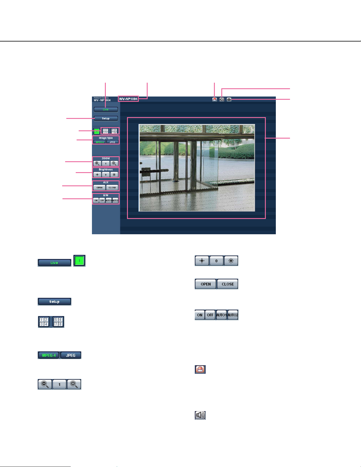
About the "Live" page
w [Setup] button
e Multi-screen buttons
r Image type buttons
t Zoom buttons
y Brightness buttons
u AUX buttons
i B/W buttons
q [Live] button
o Camera name
!0 Alarm occurrence indication button
!1 Audio button
!2 One shot button
!3 Main area
q [Live] button
Click this button to display the "Live" page. Refer to
page 7 for descriptions of how to operate the "Live"
page.
w [Setup] button *1
Click this button to display the setup menu.
e Multi-screen buttons
Click the desired multiscreen (1-4 or 5-8) button to
display images on a multiscreen.
r Image type buttons
Click the desired button to change the image type to
be displayed. The selected button will turn green.
t ZOOM buttons *2
Click the desire button to zoom in/out the displayed
image. To return the zoomed image to the original
size, click the [1] button.
y Brightness buttons *2
Adjust the brightness of images.
u AUX buttons *2
Click the desired button to open/close the AUX connector.
i B/W buttons *2
Click the desired button to switch colour of the displayed images between colour and B/W.
o Camera name
The set camera name will be displayed.
!0 Alarm occurrence indication button *2
This button will be displayed when an alarm
occurred. When this button is clicked, the alarm output connector will be reset and this button will disappear. (☞ page 30)
!1 Audio button *3
Click this button to turn on/off audio.
5
Page 6

!2 One shot button
Click this button to take a picture (a still picture). The
picture will be displayed on a newly opened window.
!3 Main area
Images from the camera will be displayed in this
area.
*1 Operable by only users whose access level is "1.
Administrator"
*2 Operable by only users whose access level is "1.
Administrator" or "2. Camera control" when "ON" is
selected for "User authentication" (☞ page 35).
*3 The access level to operate this button can be
changed by the settings of "Authentication" on the
"Audio" tab. (☞ page 26)
Refer to page 35 for further information about the
access level.
6
Page 7
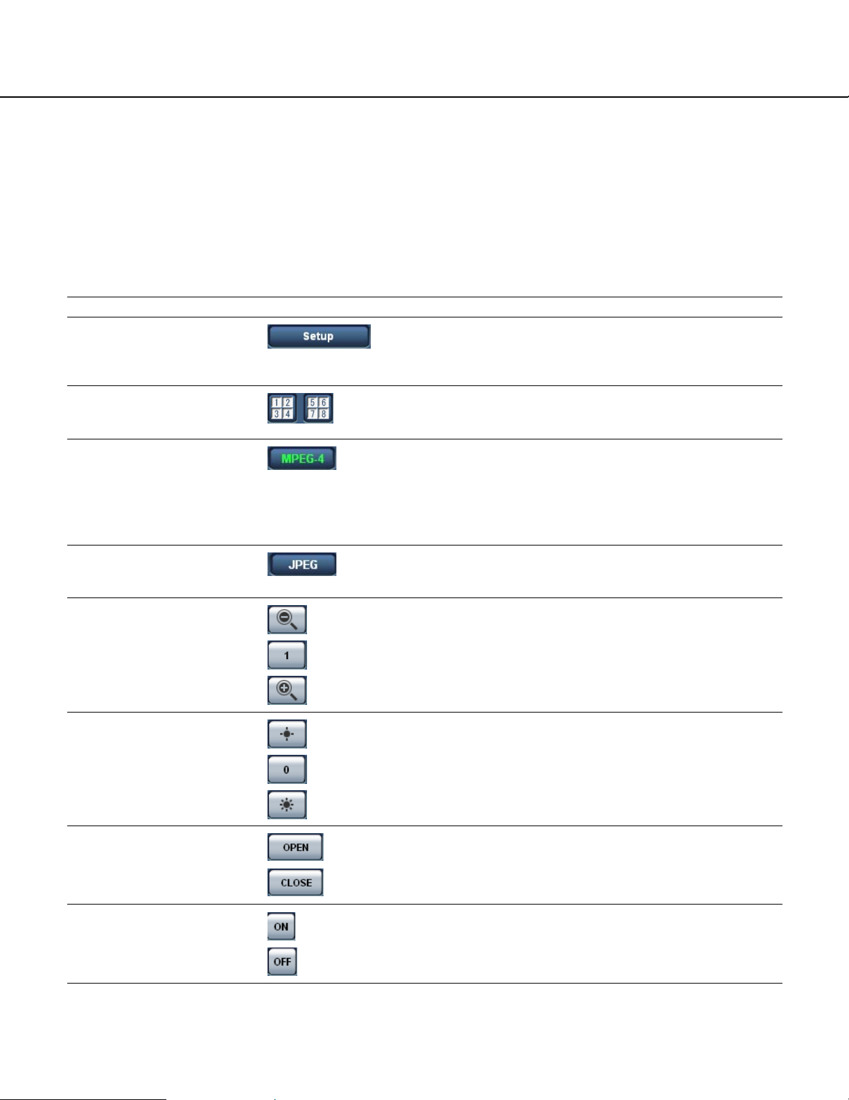
Available operations when live images are displayed
*1 Operable by only users whose access level is "1. Administrator"
*2 Operable by only users whose access level is "1. Administrator" or "2. Camera control" when "ON" is selected for
"User authentication" (☞ page 35).
*3 The access level to operate this button can be changed by the settings of "Authentication" on the "Audio" tab. (☞
page 26)
Refer to page 35 for further information about the access level.
Operation
Display the setup menu *1
Display images on a multiscreen
Display MPEG-4 image
Display JPEG image
Zoom in/out of image *2
Description
The letters "Setup" on the button will turn green and the setup
menu will be displayed.
To return to the "Live" page, click the [Live] button.
Images from multiple cameras can be displayed on a multiscreen by registering cameras on the setup menu. (☞ page 9)
The letters "MPEG-4" on the button will turn green and
MPEG-4 image will be displayed.
When "OFF" is selected for "MPEG-4 transmission" on the
setup menu, the [MPEG-4] button will not be displayed.
(☞ page 24)
The letters "JPEG" on the button will turn green and JPEG
image will be displayed.
The displayed image will be zoomed out.
The zoomed image will return to the original size.
The displayed image will be zoomed in.
Change brightness *2
Open/close the AUX connector *2
Switch colour of the displayed images between
colour and B/W *2
Image will be darker.
Image will be displayed with the standard brightness.
Image will be brighter.
The AUX connector will open.
The AUX connector will close.
Images will be displayed in B/W (black and white).
Images will be displayed in colour.
7
Page 8

Operation Description
Images will be automatically switched between colour and B/W
according to brightness (illumination).
Click this button when using the camera in the nighttime with
near-infra red rays as light source.
Acknowledge alarm occurrences *2
Turn on/off audio *3
Display a still picture (one
shot)
This button will be displayed when an alarm occurred. When
this button is clicked, the alarm output connector will be reset
and this button will disappear.
When "Latch" is selected for "Alarm output setup", the alarm
output connector will be reset by clicking this button.
(☞ page 30)
When this button is clicked, the button will turn into the
button and audio will not be heard.
When this button is clicked, the button will turn into the
button and audio will be heard.
* The [Audio] button will be displayed only when "ON" is selected for "Mic mode"
on the setup menu. (☞ page 26)
When this button is clicked, a new window will open and the
still picture (one shot) displayed on the "Live" page will be displayed on it.
To save this picture on a PC, right-click on the image and
select "Save image as…" on the displayed pop-up menu.
8
Page 9
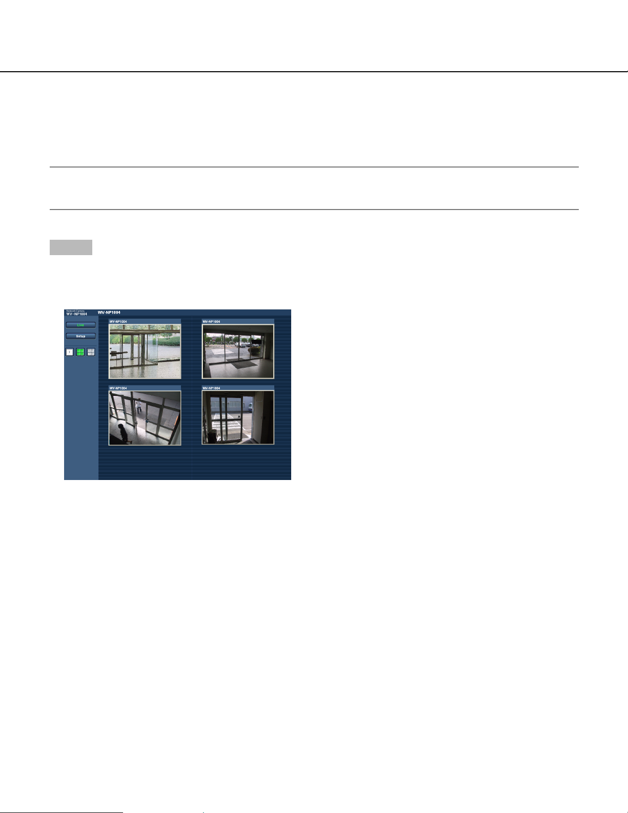
Monitor images from multiple cameras
Images from multiple cameras can be displayed on a multiscreen. Images from up to 4 cameras can be displayed
simultaneously. To display images on a multiscreen, it is necessary to register cameras in advance. 4 cameras can
be registered as a group and up to 2 groups (8 cameras) can be registered. (☞ page 27)
Important:
Select "OFF" for both the user authentication and the host authentication of the camera to be registered.
(☞ pages 35 and 36)
Step 1
Click the [Multiscreen] button.
→ Images from the registered cameras will be dis-
played on a 4-split screen.
(1) To display images on a single screen, click the the
[1] button or [Live] button.
(2) Click a camera name. Live images from the camera
corresponding to the clicked camera name will be
displayed on the "Live" page of the newly opened
window.
9
Page 10

Action at an Alarm Occurrence
The alarm action will be performed when the following alarm occur.
Alarm type
Terminal alarm: When connecting an alarm device such as a sensor to the alarm connector on the
rear of the camera, the alarm action will be performed when the connected alarm
device activated.
VMD alarm: When a motion is detected in the set VMD area, the alarm action will be performed.
* VMD stands for "Video Motion Detection".
Command alarm: When received a command alarm from the connected device via a network, the
alarm action will be performed.
Scene change detection alarm: When the camera lens is covered by something such as a cloth, or when the shoot-
ing direction of the camera is moved, the alarm action will be performed.
Action at an alarm occurrence
Display the [Alarm occurrence indication] button on the "Live" page. (☞ page 5)
The [Alarm occurrence indication] button will be displayed on the "Live" page at an alarm occurrence.
Note:
The [Alarm occurrence indication] button will be refreshed in 30 seconds intervals. For this reason, it may take a
maximum of 30 seconds until the [Alarm occurrence indication] button is displayed on the "Live" page at an alarm
occurrence.
Notify of alarm occurrences to the device connected to the alarm connector.
It is possible to output signals from the alarm connector on the rear of the camera and sound the buzzer when an
alarm occurs. The settings for the alarm output can be configured on the [Alarm] tab of the "Alarm setup" page.
(☞ page 28)
Transmit an image onto a server automatically
An alarm image can be transmitted at an alarm occurrence to the server designated in advance.
The settings required to transmit alarm image to a server can be configured on the [Alarm] tab of the "Alarm setup"
page (☞ page 28) and the [FTP] tab of the "Server setup" page (☞ page 38).
Notify of alarm occurrences by e-mail
Alarm mail (alarm occurrence notification) can be sent at an alarm occurrence to the e-mail addresses registered in
advance. Up to 4 addresses can be registered as recipients of the alarm mail. The settings for alarm mail can be
configured on the [Notification] tab of the "Alarm setup" page (☞ page 33) and the [Mail] tab of the "Server setup"
page ((☞ page 37).
Notify of alarm occurrences to the designated IP addresses (Panasonic alarm protocol)
This function is available only when Panasonic device, such as the network disk recorder, is connected to the system. When "ON" is selected for "Panasonic alarm protocol", the connected Panasonic device will be notified that the
camera is in the alarm state. The settings for Panasonic alarm protocol can be configured on the [Notification] tab of
the "Alarm setup" page. (☞ page 33)
10
Page 11

Transmit Images onto an FTP Server
Images can be transmitted to an FTP server. By configuring the following settings, transmission of images captured
at an alarm occurrence or captured at a designated interval to an FTP server will become available.
Important:
When using this function, set the user name and password to restrict users who can log into the FTP server.
Transmit an alarm image at an alarm occurrence (Alarm image FTP transmission)
An alarm image can be transmitted at an alarm occurrence to the FTP server. To transmit alarm images to an FTP
server, it is necessary to configure the settings in advance.
The settings for the FTP server can be configured on the [FTP] tab of the "Server setup" page. (☞ page 38)
The alarm image FTP transmission function can be turned on/off on the [Alarm] tab of the "Alarm setup" page.
(☞ page 28)
Note:
Depending on the network traffic, number of the transmitted images may not reach the set number of images to
be transmitted.
Transmit images at a designated interval or period (FTP periodic transmission)
Images can be transmitted at a designated interval or period. To transmit images at a designate interval or period, it
is necessary to configure the settings in advance.
The settings for the FTP server can be configured on the [FTP] tab of the "Server setup" page. (☞ page 38)
On the [Alarm] tab of the "Alarm setup" page, the FTP periodic transmission function can be turned on/off, and the
settings relating to images to be transmitted and the settings relating to schedules (periods) can be configured.
(☞ page 29)
Notes:
• Depending on the network line speed or the network traffic, images may not be transmitted at the exact designated interval or period.
• When "ON" is selected for both of the alarm image FTP transmission function and the FTP periodic transmission
function, the alarm image FTP transmission function will be given priority over the FTP periodic transmission
function. For this reason, images may not be transmitted at the exact designated interval or period if alarms
occur frequently.
11
Page 12

Save images on the SD memory card when failed to transmit images by the FTP periodic transmission function
Images failed to transmit by the FTP periodic transmission can be saved automatically on the SD memory card. To
obtain the images saved on the SD memory card, use the Windows command prompt or FTP client software. The
obtained images can be browsed on a PC.
Note:
We make no guarantee for any damages of files on the SD memory card incurred by mulfunction or error occurrence in files saved in the SD memory card regardless of what the cause may be.
Save images on the SD memory card
By configuring the following settings, saving images which had been failed to transmit to the FTP server using the
FTP periodic transmission function will become available.
About SD memory card: Use (☞ page 22)
File name: With time and date (☞ page 43)
Obtain images on the SD memory card
Step 1
Access the camera using the Windows command prompt or FTP client software.
→ The window with the user name and password entry fields will be displayed.
Step 2
Enter the user name whose access level is "1. Administrator" and its password.
→ Log in the camera.
Note:
The default user name with the access level "1. Administrator" and its password are as follows.
User Name: admin
Password: 12345
12
Page 13
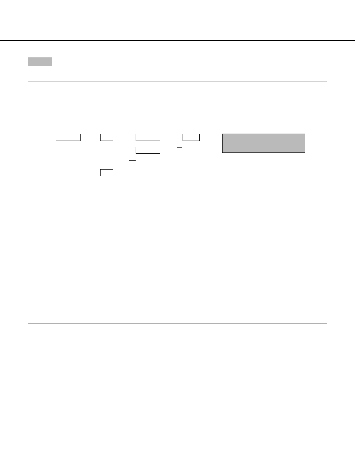
Step 3
Move the current directory to drive B and obtain images.
Notes:
• When logging in the camera, the current directory will be drive D. Images on the SD memory card can be found
in the "FTP" directory under drive B. Move to the "FTP" directory and obtain images.
<Directory structure of drive B>
Directory
Drive B FTP
LOG
Directory
(year/month/day)
050101
050102
:
:
← Destination of logs to be saved
Directory
(hour/minute)
0123
:
:
An image failed to transmit by the FTP
periodic transmission function
(Example) img_05010101230000.jpg
↑ The image will be saved here.
Example: To obtain the image (img_05010101230000.jpg) using the Windows command prompt
1. Enter "c:\>ftp 192.168.0.10" and press the [Enter] key.
→ FTP connection will be established with "192.168.0.10".
2. Log in by entering the user name and the password.
3. Enter "ftp>cd B:\FTP\050101\0123" and press the [Enter] key.
→ The current directory will be "B:\FTP\050101\0123".
4. Enter "ftp>bin" and press the [Enter] key.
→ The transfer mode will be set to the binary mode.
5. Enter "ftp>get img_05010101230000.jpg" and press the [Enter] key.
→ The image will be obtained.
6. Log out by entering "ftp>bye" and press the [Enter] key.
• It is possible to delete images on the SD memory card using the Windows command prompt, etc.
13
Page 14

About the Network Security of the Camera
Equipped security functions
The following security functions are featured in this camera.
q Access restrictions by the host authentication and the user authentication
It is possible to restrict users from accessing the camera by setting the host authentication and/or the user
authentication to on. (☞ pages 35 and 36)
w Access restrictions by changing the HTTP port
It is possible to prevent illegal access such as port scanning, etc. by changing the HTTP port number.
(☞ page 40)
Note:
When failed to pass the user authentication (authentication error) using the same IP address (PC) for a certain
times within 5 minutes, access to the camera will be denied for a while.
14
Page 15
Display the Setup Menu and Configure the Settings of the Camera Using a PC
The following are descriptions of how to configure the settings on the SETUP menu.
The setup menu is operable by only users whose access level is "1. Administrator".
How to display the setup menu
Refer to the next page for further information about
Step 1
Display the "Live" page. (☞ page 5)
Step 2
Click the [Setup] button on the "Live" page.
→ The window with the user name and password entry
fields will be displayed.
this menu.
Step 3
Click the [OK] button after entering the user name and
the password.
→ Click this button to display the setup menu.
15
Page 16
How to operate the setup menu
Step 1
Click the desired button in the frame on the left of the
window to display the respective setup menu.
When there are tabs at the top of the setup page displayed in the frame on the right of the window, click the
desired tab to display and configure the setting items
relating to the name of the tab.
When completing the setting items in field A, click
the [SET] button below field A (A-1). The edited setting items in field A will not be applied unless the
[SET] button below field A (A-1) is clicked.
In the same manner above, click the [SET] button
below field B (B-1) when completing the setting
items in field B.
Step 2
Complete each setting item displayed in the frame on
the right of the window.
Step 3
After completing each setting item, click the [SET] button to apply them.
Note:
When there are two [SET] buttons or more on the
page, click the respective button to the edited setting
item.
<Example>
A
A-1
B
B-1
16
Page 17
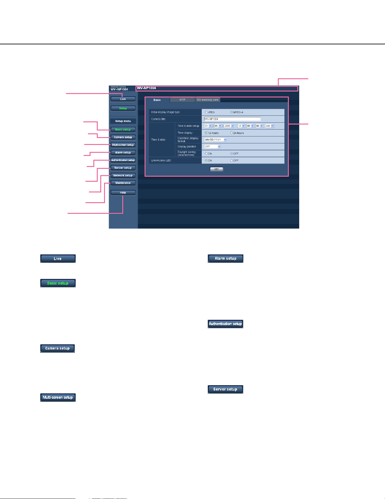
About the operation window
q [Live] button
!1 Status display
area
w [Basic setup] button
e [Camera setup] button
r [Multi-screen] button
t [Alarm setup] button
y [Authentication setup]
button
u [Server setup] button
i [Network setup] button
o [Maintenance] button
!0 [Help] button
q [Live] button
Click this button to display the "Live" page.
w [Basic setup] button
Click this button to display the "Basic setup" page.
The basic settings such as time and date, camera
name, and the settings relating to the NTP server
and the SD memory card can be configured on the
"Basic setup" page. Refer to page 19 for further
information.
e [Camera setup] button
Click this button to display the "Camera setup" page.
The settings relating images and audio such as
brightness and image quality can configured on this
page. Refer to page 23 for further information.
r [Multi-screen] button
Click this button to display the "Multi-screen setup"
page. The cameras to be used for the multi-screen
display can be registered on the "Multi-screen setup"
page. Refer to page 27 for further information.
!2 Main area
t [Alarm setup] button
Click this button to display the "Alarm setup" page.
The settings relating to alarm occurrences such as
settings for the alarm action at an alarm occurrence,
the alarm occurrence notification, and the VMD area
settings can be configured on the "Alarm setup"
page. Refer to page 28 for further information.
y [Authentication setup] button
Click this button to display the "Authentication setup"
page. The settings relating to the authentication
such as users and PCs restrictions for accessing the
camera can be configured on the "Authentication
setup" page. Refer to page 35 for further
information.
u [Server setup] button
Click this button to display the "Server setup" page.
The settings relating to the mail server and the FTP
server to which the camera accesses can be
configured on the "Server setup" page. Refer to
page 37 for further information.
17
Page 18

i [Network setup] button
Click this button to display the "Network setup" page.
The network settings and the settings relating to
DDNS (Dynamic DNS), SNMP (Simple Network
management Protocol) and FTP (File Transfer
Protocol) can be configured on the "Network setup"
page. Refer to page 39 for further information.
o [Maintenance] button
Click this button to display the "Maintenance" page.
System log check, firmware upgrade and
initialization of the setup menu can be performed on
the "Maintenance" page. Refer to page 46 for further
information.
!0 [Help] button
Click this button to display the "Help" page.
!1 Status display area
The name of the camera whose settings currently
being configured will be displayed.
!2 Main area
Pages of each setup menu will be displayed. There
are tabs for some setup menus.
18
Page 19
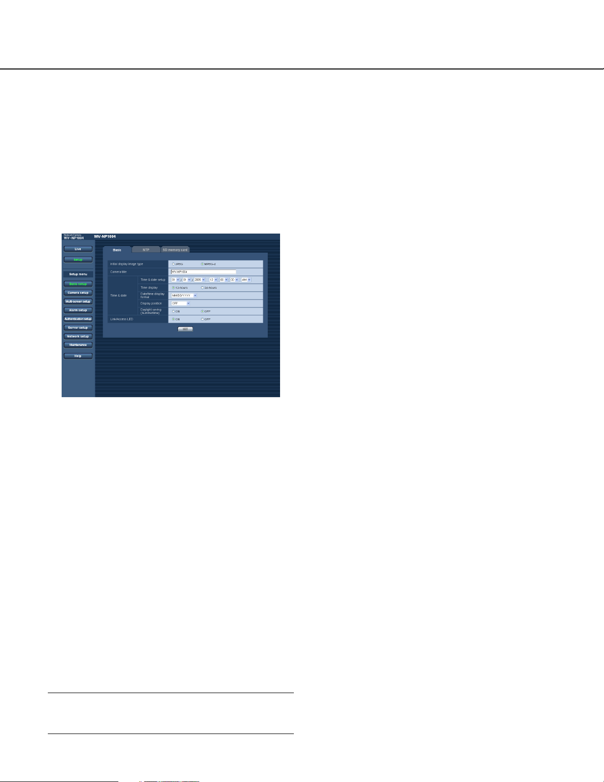
Configure the basic settings of the camera [Basic setup]
The basic settings such as time and date and camera name, and the settings relating to the NTP server and the SD
memory card can be configured on the "Basic setup" page.
The "Basic setup" page has 3 tabs of the [Basic] tab, the [NTP] tab and the [SD memory card] tab.
Configure the basic settings [Basic]
Click the [Basic] tab on the "Basic setup" page.
The settings such as the camera name, time and date, etc. can be configured on this page.
[Time display]
Select "12-hours" or "24-hours". Enter the current hour
reflecting this setting when entering the current time and
date for "Time and date setup".
Default: 24-hours
[Date/time display format]
Select a date/time display format.
When "01/04/2005 13:10:00" is set for "Time and date
setup" after selecting "24-hours" for "Time display", time
and date will be displayed as follows respectively.
DD/MM/YYYY: 01/04/2005 13:10
MM/DD/YYYY: 04/01/2005 13:10
DD/Mmm/YYYY: 01/Apr/2005 13:10
[Initial display image type]
Select "JPEG" or "MPEG-4" to determine the type of
images to be displayed when accessing the camera.
Default: MPEG-4
[Camera title]
Enter the name of the camera. Click the [SET] button
after entering the name of the camera. The entered
name will be displayed in the status display area.
Number of characters for the camera name: 0 - 20
characters
Default: WV-NP1000 (for the WV-NP1000)
WV-NP1004 (for the WV-NP1004)
[Time and date setup]
Enter the current time and date. When "12-hours" is
selected for "Time display", "AM" or "PM" can be selected.
Available range: 01/01/2005 0:00:00 –
12/31/2035 23:59:59
Default: 01/01/2005 0:00:00
Important:
Enter the current hour reflecting the selected time
display format.
YYYY/MM/DD: 2005/04/01 13:10
Mmm/DD/YYYY: Apr/01/2005 13:10
Default: MM/DD/YYYY
[Display position]
Determine whether or not to display the shooting date
and time, and the position of the date and time to be
displayed.
OFF: No shooting date and time is displayed.
ON (Upper left): The shooting date and time will be dis-
played at the upper left corner of the image display
area.
ON (Lower left): The shooting date and time will be dis-
played at the lower left corner of the image display
area.
ON (Upper right): The shooting date and time will be
displayed at the upper right corner of the image display area.
ON (Lower right): The shooting date and time will be
displayed at the lower right corner of the image display area.
Default: OFF
19
Page 20

[Daylight saving (Summertime)]
Select "ON" or "OFF" to determine whether or not to
apply daylight saving time.
ON: Applies summer time. An asterisk (*) will be dis-
played on the left side of the displayed time and
date.
OFF: Does not apply summer time.
Default: OFF
[Link/Access LED]
Select "ON" or "OFF" to determine whether or not to
light the link LED, the access LED of the network connector, and the SD memory card error LED.
Select "ON" to check the network status by lighting the
LEDs. Select "OFF" to turn off the LEDs at all times.
Default: ON
Note:
Link LED: When "ON" is selected, this LED will light
when communication with the connected device
is available.
Access LED: When "ON" is selected, this LED will
light when accessing to a network.
SD memory card error LED: This LED will light
when it is impossible to write data on the SD
memory card.
20
Page 21

Configure the settings relating to the NTP server [NTP]
Click the [NTP] tab on the "Basic setup" page. (☞ page 19)
The settings relating to the NTP server such as the NTP server address, port number, etc. can be configured on this
page.
[Synchronization interval]
Select an interval (1 - 24 hours: in 1 hour intervals) of
synchronization with the NTP server.
Default: 1 hour
[Time zone]
Select a time zone according to the location where the
camera is in use.
Default: (GMT) Greenwich Mean Time: Dublin,
Edinburgh, Lisbon, London
[Time adjustment]
Select the time adjustment method from the following.
Time adjusted by the selected method will be used as
the standard time of the camera.
Manual setup: Time set on the [Basic] tab on the
"Basic setup" page will be used as the standard time
of the camera.
Synchronization with NTP server: Time automatically
adjusted by synchronizing with NTP server will be
used as the standard time of the camera.
Default: Manual setup
[NTP server address]
Enter the IP address or the host name of the NTP server.
Number of characters for the NTP server address:
1 - 128 characters
Default: (blank)
Important:
When entering the host name for "NTP server
address", it is necessary to configure the DNS settings on the [Network] tab of the "Network setup"
page. (☞ page 39)
[NTP port]
Enter a port number to be used for the NTP server.
Available port number: 1 - 65535
Default: 123
21
Page 22

Configure the settings relating to SD memory card [SD memory card]
Click the [SD memory card] tab on the "Basic setup" page. (☞ page 19)
The settings relating to the SD memory card can be configured on this page.
[Format]
To format the SD memory card, click the [Execute] button.
Important:
• Before formatting the SD memory card, it is necessary to select "Use" for "About SD memory card" on
the [SD memory card] tab of the "Basic setup" page
and "OFF" for "FTP periodic transmission" on the
[FTP] tab of the "Network setup" page.
• Format the SD memory card only by clicking the
[Execute] button on the setup menu. Otherwise, the
following functions using the SD memory card may
not work properly with this camera.
[About SD memory card]
Select "Use" or "Not use" to determine whether or not to
use the SD memory card.
Important:
• Before removing the SD memory card from the camera, it is necessary to select "Not use" first.
• After inserting the SD memory card, it is necessary
to select "Use" to use the SD memory card.
[Information about SD memory card]
Available size and the total size of the SD memory card
will be displayed.
Depending on the state of the SD memory card, the size
indications will differ as follows.
Indication Description
----------KB/----------KB The SD card memory is not
inserted, or failed to obtain
available size due to an error,
etc.
• Save/obtain images when failed to transmit to
the FTP server using the FTP periodic transmission function
• Save/obtain the system logs
• It is recommended to use Panasonic's SD memory
card. Otherwise, the camera may not work properly
or performance deterioration may be caused.
• It is impossible to access the SD memory card in the
process of formatting.
• All data saved on the SD memory card will be deleted when the SD memory card is formatted.
• Do not turn the power of the camera off in the
process of formatting.
• After formatting the SD memory card, available size
may be smaller than the total size since the default
directory is automatically created in the SD memory
card
22
Note:
When the available size reached "0 KB", images will
not be saved on the SD memory card. It is recommended to check the available size of the SD card
memory periodically.
Page 23

Configure the settings relating to images and audio [Camera setup]
The settings relating images and audio such as brightness and image quality of JPEG/MPEG-4 can configured on
this page.
The "Camera setup" page has 3 tabs of the [JPEG/MPEG-4] tab, the [Camera] tab and the [Audio] tab.
Configure the settings relating to JPEG image [JPEG/MPEG-4]
Click the [JPEG/MPEG-4] tab on the "Camera setup" page.
Configure the settings such as "Refresh interval (JPEG)", "Image capture size" and "Image quality" on this page.
Refer to page 24 for further information about the settings relating to MPEG-4 images.
[Image capture size/Scan mode]
Select the image capture size and the resolution of
JPEG from the following.
Partial scanning QVGA, Partial scanning VGA,
Partial scanning 960x720, Full scanning QVGA,
Full scanning VGA, Full scanning 1280x960
Default: Full scanning VGA
[Image quality]
Select image quality of JPEG images from the following.
0 Super fine/1 Fine/2/3/4/5 Normal/6/7/8/9 Low
Default: 5 Normal
[Refresh interval (JPEG)*]
Select an interval to refresh the displayed JPEG image
from the following.
0.1 fps/0.2 fps/0.33 fps/0.5 fps/1 fps/2 fps/3 fps/5 fps/
6 fps */10 fps */15 fps */25 fps *
Default: 5 fps
Note:
When "ON" is selected for "MPEG-4 transmission",
the refresh intervals may be longer than the set
value when the setting value with an asterisk (*) on
the right is selected.
When the selected resolution for "Image capture
size/resolution of JPEG" is "Full scan", the maximum
refresh interval for JPEG will be 12.5 fps and the
frame rate of the analog output will be 1/2.
23
Page 24

Configure the settings relating to MPEG-4 image [JPEG/MPEG-4]
Click the [JPEG/MPEG-4] tab on the "Camera setup" page. (☞ page 23)
Configure the settings such as "Max bit rate (per 1 client)", "Image capture size" and "Image quality" on this page.
Refer to page 23 for further information about the settings relating to JPEG images.
[Refresh interval (MPEG-4)]
Select an interval (1 - 5 seconds) to refresh the displayed MPEG-4 images.
If using the network environment with frequent error
occurrences, images can be displayed quickly, and it is
possible to diminish image distortions by setting a shorter refresh interval. However, the refresh interval
(MPEG-4) may be longer than the set value.
Default: 3 sec
[Transmission type]
Select a MPEG-4 transmission type from the following.
Unicast: Up to 8 users can access a single camera
concurrently.
Multicast: No concurrent access limitation for a cam-
[MPEG-4 transmission]
Select "ON" or "OFF" to determine whether or not to
transmit MPEG-4 images.
ON: Transmits MPEG-4 images.
OFF: Does not transmit MPEG-4 images.
Default: ON
[Max bit rate (per 1 client)*]
Select a MPEG-4 bit rate per a client from the following.
64 kbps/128 kbps */256 kbps */512 kbps */1024 kbps*/
1536 kbps */2048 kbps */3072 kbps */4096 kbps *
Default: 2048 kbps *
Note:
The MPEG-4 bit rate is synchronized with "Total bit
rate" on the [Network] tab of "Network setup" page.
(☞ page 39)
For this reason, the bit rate may be lower than the
value when the setting value with an asterisk (*) on
the right is selected.
[Image capture size]
Select "QVGA" or "VGA" for the image capture size of
MPEG-4 images.
Default: VGA
[Image quality]
Select image quality of MPEG-4 images from the following.
Fine/Normal/Low
Default: Normal
era.
Default: Unicast
[Multicast address]
Enter the multicast IP address.
Available range: 224.0.0.0 - 239.255.255.255
Default: 239.192.0.20
[Multicast port]
Enter the multicast port number (used to transmit
MPEG-4 images from the camera).
Available port number: 1024 - 50000 (Only even num-
bers are available.)
Default: 37004
[Multicast TTL]
Enter the multicast TTL value.
Available value: 1 - 254
Default: 16
Important:
• Depending on the PC in use for monitoring, the multicast port number may be already in use. In this
case, it may be impossible to monitor images.
Change the multicast port number.
• When transmitting MPEG-4 image via a network, the
transmitted image sometimes may not be displayed.
In this case, refer to the network administrator.
• When two network interface cards or more are
installed on the PC in use, the network interface
card(s) not used for receiving images should be
invalidated when displaying MPEG-4 images using
the multicast port.
24
Page 25

Configure the camera settings such as image quality and brightness, etc.
[Camera]
Click the [Camera] tab on the "Camera setup" page. (☞ page 23)
The following are descriptions of how to configure the settings relating to image quality and brightness, etc. Refer to
the operating instructions (book) for further information about the setup items (camera setup page). Refer to page 49
for descriptions of how to operate the setup items (camera setup page).
Note:
The "Camera setup" page on the [Camera] tab can be displayed on a video monitor and can be configured using
the operation buttons on the camera.
Operation panel
About the operation panel
Use the following buttons on the operation panel to operate the "Camera setup" page using a PC.
[ON] button:
Click this button to display the top page of the
"Camera setup" page.
[OFF] button:
Click this button to close the "Camera setup" page.
[SET] button:
Click this button to move to the submenu.
[Left] button/ [Right] button:
Click these button to select the parameters.
[Down] button/ [Up] button:
Click these buttons to move the cursor.
[ESC] button:
Click this button to return to the previous page.
Click this button after moving the cursor onto the
desired setup item to reset to the default setting.
By clicking the [ALL RESET] button after moving the
cursor on "CAMERA RESET" on the "SPECIAL
SETUP" page (☞ page 54), all the settings except
the network settings can be reset to the default settings. However, the network settings will not be
reset.
Note:
Refer to page 48 for descriptions of how to reset the
network settings.
[RESET] button:
[ALL RESET] button:
25
Page 26

Configure the settings relating to audio [Audio]
Click the [Audio] tab on the "Camera setup" page. (☞ page 23)
The settings relating to audio can be configured on this page.
[Authentication]
Select an access level for audio transmission from the
following. Refer to page 35 for further information about
the access level.
Level 1 only/Level 2 or higher/All users
Default: All users
Note:
Images and audio will not be synchronized.
[Mic mode*]
Select "ON" or "OFF" to determine whether to turn on or
off audio on a PC.
ON: Transmits audio from the camera to the PC. Audio
can be heard with images on the PC. Images and
audio will not be synchronized.
OFF: Does not transmit audio from the camera to the
PC. Therefore, no settings and controls relating
audio will be invalidated.
Default: ON
[Audio bit rate]
Select "16 kbps" or "32 kbps" for audio bit rate.
Default: 32 kbps
[Audio sensitivity]
Select the sensitivity of the built-in microphone of the
camera from the following.
High/Middle/Low
Default: Middle
[Transmission interval]
Select an interval for audio transmission from the followings.
20 msec/40 msec/80 msec/160 msec
Default: 40 msec
26
Page 27

Configures the multi-screen settings [Multi-screen setup]
The cameras to be used for the multi-screen display can be registered on this page.
Refer to page 9 for descriptions of how to display images on a multi-screen.
[IP Address]
Enter the IP address or the host name of the camera to
be used for the multi-screen. 4 cameras can be registered as a group and up to 2 groups (8 cameras) can be
registered.
When the HTTP port number for the camera had
been changed, enter as follows:
"IP address of the camera:port number", for example
"192.168.0.10:8080".
Number of characters for the IP address: 1 - 128
characters
[Camera title]
The entered camera title will be displayed on a multiscreen.
Number of characters for the camera title: 0 - 20
characters
27
Page 28

Configure the alarm settings [Alarm setup]
The settings relating to alarm occurrences such as settings for the alarm action at an alarm occurrence, the alarm
occurrence notification, and the VMD area settings can be configured on this page.
The "Alarm setup" page has 3 tabs of the [Alarm] tab, the [VMD area] tab and the [Notification] tab.
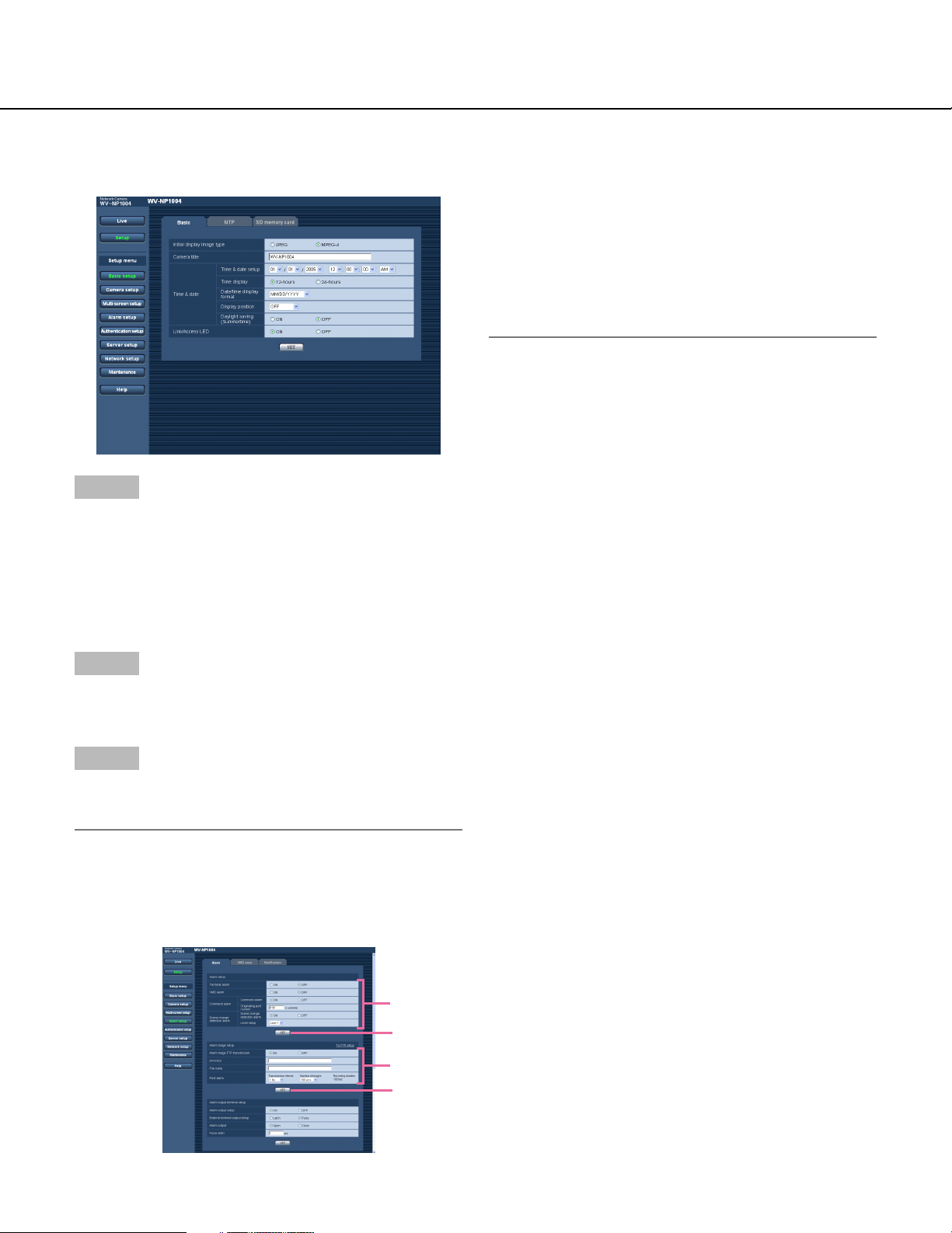
Configure the settings relating to the alarm action [Alarm]
Click the [Alarm] tab on the "Alarm setup" page.
The settings relating to the alarm action can be configured on this page. Refer to pages 29 and 30 for further information about the settings relating to the alarm image and the alarm out connector.
[Originating port number]
Select a port number to be used to receive the command alarm.
Available port number: 1 - 65535
Default: 8181
[Scene change detection alarm]
Select "ON" or "OFF" to determine whether or not to
perform the alarm action when the camera lens is covered by something such as a cloth, or when the shooting direction of the camera is moved.
Default: OFF
[Terminal alarm]
Select "ON" or "OFF" to determine whether or not to
receive the terminal alarm.
Default: OFF
[VMD alarm]
Select "ON" or "OFF" to determine whether or not to
perform the alarm action using the VMD function. Refer
to page 31 for further information about the VMD area
settings.
Default: OFF
[Command alarm]
Select "ON" or "OFF" to determine whether or not to
receive the command alarm.
The command alarm is the function that notifies of
Panasonic protocol alarm from the other cameras.
When "ON" is selected, alarm actions will be performed
between multiple cameras.
Default: OFF
[Level setup]
Select the sensitivity of the scene change detection
alarm function from the following.
Level 1/Level 2/Level 3
Default: Level 1
28
Page 29

Configure the settings relating to the alarm image [Alarm image setup]
Click the [Alarm] tab on the "Alarm setup" page. (☞ page 28)
The settings relating to the alarm image to be transmitted to the FTP server can be configured on this page. The
alarm image will be transmitted to the FTP server. To transmit alarm images to the FTP server, it is necessary to
configure the settings in advance. (☞ page 38)
The settings for resolution and image quality on the "JPEG/MPEG-4" tab (☞ page 23) will be applied to alarm
images.
Refer to pages 29 and 30 for further information about the settings relating to the alarm image and the alarm out
connector.
[Transmission interval]
Select the transmission interval for the alarm image FTP
transmission from the following.
0.1 fps/0.2 fps/0.33 fps/0.5 fps/1 fps
Default: 1 fps
[Number of images]
Select the number of images to be transmitted from the
following.
10 pics/20 pics/30 pics/50 pics/100 pics/1000 pics/
2000 pics/3000 pics/4000 pics/5000 pics
Default: 100 pics
[Alarm image FTP transmission]
Select "ON" or "OFF" to determine whether or not to
transmit the alarm image to the FTP server.
Default: OFF
[Directory]
Enter the directory name where the alarm images are to
be saved.
Number of characters for the directory name:
0 - 256 characters
[File name]
Enter the file name used for the alarm image to be
transmitted to the FTP server. The file name will be as
follows.
["Entered file name" + "Time and date (year/month/day/
hour/minute/second)"] + "Serial number"
Number of characters for the file name: 1 - 32 char-
acters
Default: (blank)
[Recording duration]
Approximate time to be taken to save the set "number of
images" with the set "transmission interval" will be displayed.
29
Page 30

Configure the settings relating to the alarm out connector [Alarm output setup]
Click the [Alarm] tab on the "Alarm setup" page. (☞ page 28)
The settings relating to the alarm out connector can be configured on this page. Refer to pages 29 and 30 for further
information about the settings relating to the alarm image and the alarm out connector.
Note:
When "Close" is selected, the alarm signal will be
output for around 1 minute when the power of the
camera is turned on.
[Pulse width]
When "Pulse" is selected for "Alarm output", select an
pulse width.
Available pulse width: 1 - 120 sec
Default: 1 sec
[Alarm output setup]
Select "ON" or "OFF" to determine whether or not to
output the alarm signals to the alarm out connector
when an alarm is detected.
Default: OFF
[External terminal output setup]
Select "Latch" or "Pulse" for the alarm out connector at
an alarm occurrence.
Latch: When an alarm is detected, alarm output con-
nector will be in the state selected for "Alarm output"
until the [Alarm reset] button is clicked.
Pulse: When an alarm is detected, alarm output con-
nector will be in the opposite state to the "Alarm output" setting for the period set for "Pulse width".
Default: Latch
[Alarm output]
Select "Open" or "Close" to determine whether to open
or close the alarm output connector when output the
alarm signals.
Open: The alarm out connector will open when output
the alarm signals.
Close: The alarm out connector will close when output
the alarm signals.
Default: Open
30
Page 31

Set the VMD areas [VMD area]
Click the [VMD area] tab on the "Alarm setup" page. (☞ page 28)
The video motion detection areas can be set on this page.
When a motion is detected in the set area, the alarm action will be performed.
Note:
It will take around 5 minutes to start detection after the power is turned on.
Set the VMD areas
Step 1
Set the video motion detection area by dragging the
mouse on the screen. When the [All areas] button is
clicked, the whole area will become the VMD area, and
"1 (White)" will be automatically applied to "Area".
→ The designated area will become the VMD area and
the outline will be displayed. When 2 - 4 VMD areas
are set, each area will be numbered in order. The
areas will be identified by the respective outline colours.
Step 2
Select "ON" or "OFF" for "Status" of each VMD area.
When the [SET] button is clicked after selecting "OFF",
the outline will become the broken line and no alarm
action will be performed even when a motion is detected
in the area.
Step 3
Select "Detect" or "Mask" for "Type" of each VMD area.
When "Mask" is selected, the respective VMD area will
be shaded. Any motion will not be detected in the VMD
area for which "Mask" is selected. Select "Mask" for the
area where any motion is not to be detected.
Step 4
Select the detection sensitivity from the following.
When "Mask" is selected for "Type", this setting will be
invalid for the respective VMD area.
High/Middle/Low
Default: Middle
Step 5
Select the direction from the following. Only a motion
that moves to the selected direction will be detected.
When "Mask" is selected for "Type", this setting will be
invalid for the respective VMD area.
None/Up/Down/Left/Right
Default: None
31
Page 32

Step 6
Select "ON" or "OFF" for "Light detection control".
When "ON" is selected, detection errors caused by turning lighting on/off can be diminished.
Notes:
• Complete prevention of detection error is not guaranteed even if using this function.
• When "ON" is selected, performance of the motion
detection may be lower.
Step 7
Click the [SET] button after completing the settings.
Important:
The setting will not be applied unless the [SET] button is clicked.
Delete the set VMD area
Step 1
Click the [DEL] button respective to the area to be deleted.
→ The outline of the area will disappear and the select-
ed area will be deleted.
Step 2
Click the [SET] button after completing settings.
32
Page 33

Configure the settings relating to the mail notification [Notification]
Click the [Notification] tab on the "Alarm setup" page. (☞ page 28)
The settings relating to the alarm mail can be configured on this page. To notify of an alarm occurrence by e-mail, it
is necessary to configure the settings of the mail server. (☞ page 37)
[E-mail notification]
Select "ON" or "OFF" to determine whether or not to
notify of an alarm occurrence by e-mail at an alarm
occurrence.
Default: OFF
[Address]
Enter the destination mail address. Up to 4 destination
addresses can be registered.
To notify by e-mail, check the "Notification setup" checkbox respective to the desired address. To delete the
registered address, click the [DEL] button respective to
the desired address.
Number of characters for the destination mail
address: 3 - 128 characters
[Mail subject]
Enter the mail subject.
Number of characters for the mail subject: 0 - 50
characters
[Mail body]
Enter the mail body.
Number of characters for the mail body: 0 - 200 char-
acters
33
Page 34

Configure the settings relating to Panasonic alarm protocol [Panasonic alarm protocol setup]
Click the [Notification] tab on the "Alarm setup" page. (☞ page 28)
The settings relating to Panasonic alarm protocol can be configured on this page.
[Panasonic alarm protocol]
Select "ON" or "OFF" to determine whether or not to
notify of an alarm occurrence by Panasonic alarm protocol when an alarm is detected.
Default: OFF
[Destination port]
Select a destination port of the Panasonic alarm protocol from the following.
Available port number: 1 - 65535
Default: 1818
[Retry times]
Select a retry time of Panasonic alarm protocol.
Available retry times: 1 - 30
Default: 2
[IP address]
Enter the destination IP address of the Panasonic alarm
protocol from the following. Up to 8 destination addresses can be registered.
To notify by Panasonic alarm protocol, check the
"Notification setup" checkbox respective to the desired
IP address. To delete the registered IP address, click
the [DEL] button respective to the desired IP address.
34
Page 35

Configure the settings relating to the authentication [Authentication setup]
The settings relating to the authentication such as users and PCs (IP addresses) restrictions for accessing the camera can be configured on the "Authentication setup" page.
The "Authentication setup" page has 2 tabs of the [User] tab and the [Host] tab.
Configure the settings relating to the user authentication [User]
Click the [User] tab on the "Authentication setup" page.
The settings relating to the user authentication can be configured on this page. Up to 16 users can be registered.
[Access level]
Select the access level of the host from the following.
1. Administrator: Allowed all available operations of
the camera.
2. Camera control: Allowed to display images from the
camera and to control the camera. The camera setting configuration is unavailable.
3. Live only: Only displaying live images is available.
The camera setting configuration and camera control are unavailable.
Default: 3. Live only
[User authentication]
Select ON or OFF to determine whether or not to
authenticate the user.
Default: OFF
[User name]
Enter a user name.
Number of characters for the user name: 1 - 32 char-
acters
Default: (blank)
[Password] [Retype password]
Enter the password.
Number of characters for the password: 4 - 32 char-
acters
Default: (blank)
Note:
When the user name already in use is entered and
the [REG] button is clicked, the respective user information will be overwritten.
Note:
By clicking [i] of "User name check", the registered
user can be selected and the selected user’s information can be checked.
The registered user will be displayed with the access
level. (Example: admin [1])
To delete the registered user, click the [DEL] button
after selecting the user to be deleted.
35
Page 36

Configure the settings relating to the host authentication [Host]
Click the [Host] tab on the "Authentication setup" page. (☞ page 35)
The settings to restrict PCs (IP address) to access the camera can be configured on this page.
Note:
By clicking [i] of "Host check", the registered host
can be selected and the selected host’s IP address
can be checked.
The registered IP address will be displayed with the
access level. (Example: 192.168.0.21 [1])
To delete the registered host, click the [DEL] button
after selecting the IP address to be deleted.
[Host authentication]
Select ON or OFF to determine whether or not to
authenticate the host.
Default: OFF
Important:
Before configuring the host authentication, it is necessary to register IP addresses of the PCs to be
allowed to access the camera and determine their
access levels. If "ON" is selected for "Host authentication" before registering the hosts (IP addresses), it
will be impossible to access the camera.
[IP Address]
Enter the IP address of the PC to be allowed to access
the camera.
Notes:
• When "IP address/subnet mask" is entered, it is possible to restrict PCs in each subnet.
• When the IP address already in use is entered and
the [REG] button is clicked, the respective host information will be overwritten.
[Access level]
Select the access level of the host from the following.
1. Administrator/2. Camera control/3. Live only
Refer to page 35 for further information about the
access level.
Default: 3. Live only
36
Page 37

Configure the settings of the servers [Server setup]
The settings relating to the mail server and the FTP server can be configured on this page.
The "Server setup" page has 2 tabs of the [Mail] tab and the [FTP] tab.
Configure the settings relating to the mail server [Mail]
Click the [Mail] tab on the "Server setup" page.
The settings relating to the mail server used to send the alarm mail can be configured on this page.
[Authentication]
Select the authentication method to send e-mails from
the following.
None: It is unnecessary to clear any authentication to
send e-mails.
POP before SMTP: It is necessary to clear the POP
server authentication first to use the SMTP server to
send e-mails.
SMTP: It is necessary to clear the SMTP server authen-
tication to send e-mails.
Default: None
[User name]
Enter the user name to access the server.
[SMTP server address]*
Enter the IP address or the host name of the SMTP
server used to send e-mails.
Number of characters for the SMTP server address:
1 - 128 characters
[POP server address]*
When "POP before SMTP" is selected for
"Authentication", enter the IP address or the host name
of the POP server.
Number of characters for the POP server address:
1 - 128 characters
* Important:
When entering the host name for "POP server
address", it is necessary to configure the DNS settings on the [Network] tab of the "Network setup"
page. (☞ page 39)
Number of characters for the user name: 1 - 32 char-
acters
[Password]
Enter the password to access the server.
Number of characters for the password: 0 - 32 char-
acters
[Sender mail address]
Enter the mail address of a sender.
Entered mail address will be displayed in the "From"
(sender) line of the sent mails.
Number of characters for the sender address:
3 - 128 characters
37
Page 38

Configure the settings relating to the FTP server [FTP]
Click the [FTP] tab on the "Server setup" page. (☞ page 37)
The settings relating to the FTP server used to transmit the alarm images can be configured on this page.
[FTP mode]
Select "Passive" or "Active" for the FTP mode.
Normally, select "Passive". When failed to establish the
connection, select "Active".
Default: Passive
[FTP server address]
Enter the IP address or the host name of the FTP server.
Number of characters for the FTP server address:
1 - 128 characters
Important:
When entering the host name for "FTP server
address", it is necessary to configure the DNS settings on the [Network] tab of the "Network setup"
page. (☞ page 39)
[User name]
Enter the user name (login name) to access the FTP
server.
Number of characters for the user name: 1 - 32 char-
acters
[Password]
Enter the password to access the FTP server.
Number of characters for the password: 0 - 32 char-
acters
[Control port]
Enter a control port number to be used for the FTP server.
Available port number: 1 - 65535
Default: 21
38
Page 39

Configuring the network settings [Network setup]
The network settings and the settings relating to DDNS (Dynamic DNS) and SNMP (Simple Network management
Protocol) can be configured on this page.
The "Network setup" page has 3 tabs of the [Network] tab, the [DDNS] tab, the [SNMP] tab and the [FTP] tab.
Configure the network settings [Network]
Click the [Network] tab on the "Network setup" page.
The following information is required to configure the network settings.
Contact the network administrator or your Internet service provider.
• IP address
• Net mask
• Default gateway (when using the gateway server/router)
• HTTP port
• Primary DNS, Secondary DNS (when using DNS)
<Unavailable IP addresses>
0.*.*.*
*.*.*.0
255.*.*.*
*.*.*.255
127.0.0.1
Class D address (224.0.0.0 - 239.255.255.255)
Class E address (240.0.0.0 - 255.255.255.255)
[DHCP]
Select "ON" or "OFF" to determine whether or not to use
the DHCP function.
Default: OFF
[IP address]
When not using the DHCP function, enter the IP
address of the camera. Do not enter the IP address
already in use (for the PCs and the other network cameras).
Default: 192.168.0.10
[Net mask]
When not using the DHCP function, enter the net mask
of the camera.
Default: 255.255.255.0
[Default gateway]
When not using the DHCP function, enter the default
gateway of the camera.
Default: 192.168.0.1
<Unavailable IP addresses for the default gateway>
0.*.*.*
*.*.*.0
255.*.*.*
*.*.*.255
127.0.0.1
Class D address (224.0.0.0 - 239.255.255.255)
Class E address (240.0.0.0 - 255.255.255.255)
39
Page 40

[HTTP port]
Assign the port numbers independently.
The following port numbers are unavailable since they
are already in use.
Available port number: 1 - 65535
Default: 80
<Port numbers already in use>
20, 21, 23, 25, 42, 53, 67, 68, 69, 110, 123, 161,
162, 995, 10669, 10670
[DNS]
Select "AUTO" or "MANUAL" to determine whether or
not to use the DNS. When "MANUAL" is selected, it is
necessary to configure the settings for the DNS.
When using the DHCP function, it is possible to obtain
the DNS address automatically by selecting "AUTO".
Refer to the network administrator for further information
about the settings.
Default: MANUAL
[Primary DNS], [Secondary DNS]
When "MANUAL" is selected for "DNS", enter the IP
address of the DNS. Refer to the network administrator
about the IP address of the DNS.
Notes:
• When selecting "64 kbps", select "OFF" for "Mic
mode" on the "Audio" tab. (☞ page 26)
• When 64 kbps is selected, it is impossible to carry
out the live-transmission of JPEG images and the
FTP periodic transmission simultaneously.
[Line speed]
Select the line speed for data transmission from the followings. It is recommended to use with the default setting "AUTO".
AUTO/100MF (Mbps full-duplex)/100MH (Mbps halfduplex)/10MF (Mbps full-duplex)/10MH (Mbps halfduplex)
Default: AUTO
[FTP access]
Select "Allow" or "Forbid" to determine whether to allow
or forbid the FTP access.
Default: Allow
[Total bit rate]
Select the total bit rate for data transmission from the
followings.
64 kbps/128 kbps/256 kbps/512 kbps/1024 kbps/
2048 kbps/4096 kbps/10 Mbps/Unlimited
Default: Unlimited
40
Page 41

Notes:
• The port forwarding function changes a global IP address to a private IP address, and "Static IP masquerade"
and "Network Address Translation (NAT)" have this function. This function is to be set in a router.
• To access the camera via the Internet by connecting the camera to a broadband router, it is necessary to assign
a respective port number for each camera and address translation by using the port forwarding function. For further information, refer to the operating instructions of the broadband router in use.
Enter [Global IP address + :
(colon) + port number] in the
"Address" box of the browser
via the Internet.
vvv.xxx.yyy.zzz:82
vvv.xxx.yyy.zzz:81
Internet
(WAN)
Global address
for the WAN
vvv.xxx.yyy.zzz
Cable modem
xDSL modem
Broadband router
Address translation using the port
forwarding function
vvv.xxx.yyy.zzz:82 → 192.168.0.2:82
Address translation using the port
forwarding function
vvv.xxx.yyy.zzz:81 → 192.168.0.1:81
Private address
for the LAN
192.168.0.254
Private address
192.168.0.2
Port number: 82
Private address
192.168.0.1
Port number: 81
Configure the settings relating to DDNS [DDNS]
Click the [DDNS] tab on the "Network setup" page. (☞ page 39)
The settings relating to DDNS can be configured on this page.
When using the DDNS function, it is possible to access with "Host name registered in the DDNS server.nmdns.net".
To use the DDNS function, it is necessary to connect to the dedicated DDNS server. Refer to the web site for further
information about the DDNS. Refer to the "Readme" file about the web site.
It is necessary to configure the host name, user name and password registered in the DDNS server.
[DDNS]
Select "ON" or "OFF" to determine whether or not to use
the DDNS function.
Default: OFF
[Host name]
Enter the host name to be used.
Number of characters for the host name: 1 - 64 char-
acters
[User name]
Enter the user name (login name) to access the DDNS
server.
Number of characters for the user name: 1 - 32 char-
acters
41
Page 42

[Password]
Enter the password to access the DDNS server.
Number of characters for the password: 0 - 32 char-
acters
[Access interval]
Select the interval to access the DDNS server to check
the IP address and the host name from the following.
1 min/10 min/30 min/1 hour/6 hours/24 hours
Default: 1 hour
Configure the settings relating to SNMP [SNMP]
Click the [SNMP] tab on the "Network setup" page. (☞ page 39)
The settings relating to SNMP can be configured on this page. It is possible to check the status of the camera by
connecting to the SNMP manager. When using the SNMP function, contact the network administrator.
[Camera location]
Enter the name of the location where the camera is
installed.
Number of characters for the camera location: 0 - 32
characters
Default: (blank)
[Contact (Destination address or phone number of
manager)]
Enter the mail address or the phone number of the
SNMP manager.
Number of characters for the destination address or
the phone number of manager: 0 - 255 characters
Default: (blank)
[Community name]
Enter the community name to be monitored.
Number of characters for the community name:
0 - 32 characters
Default: (blank)
Important:
When using the SNMP function, it is necessary to
enter the community name. When no community
name is entered, the SNMP function will not work.
[Camera title]
Enter a camera title to be used to manage the camera
with the SNMP function.
Number of characters for the camera title: 0 - 32
characters
Default: WV-NP1000 (for the WV-NP1000)
WV-NP1004 (for the WV-NP1004)
42
Page 43

Configure the settings relating to the FTP periodic transmission [FTP periodic
transmission]
Click the [FTP] tab on the "Server setup" page. (☞ page 37)
The settings relating to the periodic transmission of images to an FTP server can be configured on this page. To
transmit images to an FTP server periodically, it is necessary to configure the settings of the FTP server in advance.
(☞ page 38)
Refer to page 44 for descriptions of how to configure schedules of image transmission.
Important:
• Depending on the network line speed or the network traffic, images may not be transmitted at the exact designated interval or period.
• When "ON" is selected for both of the alarm image FTP transmission function and the FTP periodic transmission
function, the alarm image FTP transmission function will be given priority over the FTP periodic transmission
function. For this reason, images may not be transmitted at the exact designated interval or period if alarms
occur frequently.
Note:
Images failed to transmit by the FTP periodic transmission can be saved automatically on the SD memory card.
[File name]
Enter the file name (name of the image file to be transmitted) and select the naming option from the following.
With time and date: File name will be ["Entered file
name" + "Time and date (year/month/day/hour/
minute/second)" + "00"].
Without time and date: File name will be the charac-
ters entered for "File name" only. When "Without
time and date" is selected, the file will be overwritten
each time a file is transmitted newly.
Number of characters for the file name: 1 - 32 char-
acters
Default: (blank)
[FTP periodic transmission]
Select "ON" or "OFF" to determine whether or not to
transmit images using the FTP periodic transmission
function.
When "ON" is selected, it is necessary to configure the
settings of the FTP server. (☞ page 38)
Default: OFF
[Directory]
Enter the directory name where the images are to be
saved.
Number of characters for the directory name:
0 - 256 characters
Default: (blank)
[Interval]
Select the interval for the FTP periodic transmission
from the following.
1 sec/2 sec/3 sec/4 sec/5 sec/6 sec/10 sec/15 sec/
20 sec/30 sec/1 min/2 min/3 min/4 min/5 min/6 min/
10 min/15 min/20 min/30 min/1 hour/1.5 hours/2 hours/
3 hours/4 hours/6 hours/12 hours/24 hours
Default: 1 sec
43
Page 44

Configure the schedule settings of the FTP periodic transmission [Schedule
setup]
Click the [FTP] tab on the "Server setup" page. (☞ page 37)
The schedule settings of the FTP periodic transmission can be configured on this page. Refer to page 38 for further
information about the settings relating to the FTP periodic transmission.
How to configure the schedule settings
Step 1
Check the check box of the desired day of the week.
→ The selected day of the week will be validated for
the schedule.
Step 2
To designate time, click [i] and select the desired
"hour" and "minute".
When not designating time, check the checkbox of "24
hours".
Step 3
Click the [SET] button after completing the settings.
→ The result will be displayed at the bottom of the win-
dow.
44
Page 45

How to delete the set schedule
Step 1
Uncheck the check box of the set day of the week.
Step 2
Click the [SET] button after completing the settings.
→ The result will be displayed at the bottom of the win-
dow.
45
Page 46

Maintenance of the camera [Maintenance]
System log check, firmware upgrade, and initialization of the setup menu can be performed on this page.
The "Maintenance" page has 3 tabs of the [System log] tab, the [Upgrade] tab and the [Initialization] tab.
Check the system log [System log]
Click the [System log] tab of the "Maintenance" page.
Up to 4000 system logs can be saved on the SD memory card when the SD memory card is inserted after selecting
"Use" for "About the SD memory card" on the [SD memory card] tab (☞ page 22).
When "Not use" is selected for "About the SD memory card", up to 100 system logs can be saved on the built-in
memory of the camera.
When the saved system logs reached the maximum number, the older system logs will be overwritten by the newer
logs. In this case, the oldest log is the first to be overwritten.
The system logs will be displayed in 100 logs each.
[Time & date]
Time and date at the error occurrence will be displayed.
[Error message]
The descriptions about the error will be displayed.
Refer to page 63 for further information about the system logs.
46
Page 47

Upgrade the firmware [Upgrade]
Click the [Upgrade] tab of the "Maintenance" page. (☞ page 46)
The current firmware can be checked and upgraded to the latest version on this page. Contact the dealer for further
information about the firmware upgrade.
Step 4
Click the [Upgrade] button.
→ The confirmation window will be displayed. When
"Do not reset the settings after completing the
upgrade." was selected, the confirmation window will
not be displayed.
Important:
• Upgrade the firmware using a PC in the same subnet as of the camera’s.
• Follow the instruction of the dealer when upgrading
the firmware.
• Use the designated file (extension:img) for the
[Model No.], [MAC address], [Firmware version],
[IPL version], [DSP version]
Information of each item will be displayed.
How to upgrade the firmware
Step 1
Contact the dealer and download the latest firmware
onto a PC.
Important:
A blank (space) cannot be used for the name of the
directory where the downloaded firmware to be
saved.
firmware upgrade.
• The name of the firmware to be used for upgrade
should be "firmware.img".
• Do not turn the power of the camera off in the
process of upgrade.
• Do not operate the web browser (including adjusting
the window size) in the process of upgrade.
• The following network settings will not be initialized
when upgrade the firmware after selecting "Reset to
the default setting after completing the upgrade.
(Except the network settings)".
IP address, net mask, default gateway, HTTP port,
ON/OFF for DHCP, SNMP setup
Step 2
Click the [Browse…] button and designate the downloaded firmware.
Step 3
Click the radio button respective to the desired option to
determine whether or not to initialize the settings after
completing the firmware upgrade.
47
Page 48

Initialize/restart the camera [Initialization]
Click the [Initialization] tab of the "Maintenance" page. (☞ page 46)
Initialization of the settings and data of the camera and restarting of the camera can be performed on this page.
[Restart]
Click the [Execute] button to restart the camera. It is
impossible to operate the camera for around 2 minutes
after the restart just as when the power is turned on.
Note:
Turn on the power of the camera while holding down
the [INITIAL SET] button of the camera, and wait
around 5 seconds without releasing the [INITIAL
SET] button.
Wait around 30 seconds after releasing the button.
The settings including the network settings will be
initialized.
[Initialize setup data]
Click the [Execute] button to reset the settings to the
default settings. However, the network settings will not
be reset.
It is impossible to operate the camera for around 2 minutes after the initialization.
[Initialize HTML data]
Click the [Execute] button to reset the HTML files to the
default settings. It is impossible to operate the camera
for around 2 minutes after the initialization.
[Initialize setup data and HTML data]
Click the [Execute] button to reset the settings and the
HTML files to the default settings. However, the network
settings will not be reset.
It is impossible to operate the camera for around 2 minutes after the initialization.
48
Page 49

Configure the Camera Settings such as Image Quality, Brightness, etc.
The following are descriptions of how to configure the settings such as image quality, brightness, privacy zone and
flange-back length, etc.
The settings can be configured in the following methods.
• Configure the settings using a PC
The setting can be configured on the [Camera] tab of the "Camera setup" page. Refer to page 23 for further information.
• Configure the settings using the operation buttons on the camera
The settings can be configured on the "CAMERA SETUP" page displayed on a video monitor connected to the
video output connector. Refer to the operating instructions (book) for further information.
Note:
The illustrations below are the examples of the setup pages to be displayed on a video monitor.
Configure the settings relating to the camera operations [CAMERA SETUP]
Configure the settings relating to camera operations. The settings can be configured on the "CAMERA SETUP"
page.
Refer to the operating instructions (book) or page 25 for descriptions of how to display the "CAMERA SETUP" page.
CAMERA SETUP page
**CAMERA SETUP** 1/2
CAMERA ID OFF
ALC/ELC ALC
SHUTTER OFF
AGC ON(HIGH)
SENS UP OFF
SYNC INT
WHITE BAL ATW1
DNR HIGH
BW MODE
PRIVACY ZONE OFF
EL-ZOOM OFF
**CAMERA SETUP** 2/2
STABILIZER OFF
RET TOP END
[CAMERA ID]
Select "ON" or "OFF" to determine whether to enable or
disable the camera title display. When "ON" is selected,
the set camera title will be displayed. Refer to page 56
for descriptions of how to edit the camera title.
Default: OFF
Number of characters for the camera ID: 16 charac-
ters
[ALC/ELC]
Select the light control method from the following
according to the lens in use.
Refer to page 57 for descriptions of how to compensate
backlight.
ALC: Auto backlight compensation controls light
amount according to brightness of subjects. When
using an ALC lens, select this parameter.
ALC+: Auto backlight compensation and the electronic
shutter control light amount according to brightness
of subjects. When shooting bright subjects using an
ALC lens, select this parameter.
Note:
When shooting under fluorescent lamps, flicker may
occur.
ELC: When using a fixed iris lens, select this parameter.
Default: ALC
[SHUTTER]
Select the shutter speed.
The following will be available by changing the shutter
speed.
When a fast shutter speed (up to 1/10000) is set, the
camera can shoot a fast motion of a subject without outof focus blur.
When shooting under fluorescent lamps (operating at 60
Hz), flicker may occur. When the faster shutter speed is
set, flicker may be caused more frequently. By setting
the shutter speed to "1/60" or "1/120", flicker caused by
fluorescent lamps can be diminished.
49
Page 50

The following are available for the shutter speed.
When "Full scan" is selected for resolution:
OFF (1/12.5), 1/25, 1/50, 1/60, 1/120, 1/250, 1/500,
1/1000, 1/2000, 1/4000, 1/10000
When "Partial scan" is selected for resolution:
OFF (1/50), 1/120, 1/250, 1/500, 1/1000, 1/2000,
1/4000, 1/10000
Default: 1/25
Notes:
• When "ALC+" or "ELC" is selected for "ALC/ELC",
shutter speed selection is unavailable. The "---" indication will be displayed for the shutter speed.
• When a fast shutter speed is selected, sensitivity will
become lower and smear may appear under a bright
light source.
[AGC]
Select a method of gain adjustment from the following.
ON (HIGH)/ON (MID)/ON (LOW): When illuminance of
subject becomes darker, gain will be automatically
incremented and screen will become brighter.
"HIGH", "MID" and "LOW" are indications of gain
level.
OFF: Gain will not be incremented.
Default: ON (HIGH)
[SENS UP]
Adjust the sensitivity.
When using the sensitivity-up function, image will
become brighter by amplified light intensity. When "FIX"
is selected, amplification rate will be fixed. When
"AUTO" is selected, amplification rate will change automatically according to illuminance of subject.
The following are available for the sensitivity-up.
OFF/X2 AUTO/X4 AUTO/X6 AUTO/X10 AUTO*/OFF/
X2 FIX/X4 FIX/X6 FIX/X10 FIX*/X16 FIX*/X32 FIX*
* Available only when "Partial scan" is selected for reso-
lution.
Default: OFF
Notes:
• When "1/30" is selected for "SHUTTER" (when "Full
scan" is selected for resolution), "1/100" is selected
for "SHUTTER" (when "Partial scan" is selected for
resolution), or "ALC+" or "ELC" is selected for
"ALC/ELC", only "AUTO" parameters are available.
When selecting any of "1/25" - "1/120" for "SHUTTER", select a parameter for "SENS UP" after setting a parameter for "SHUTTER".
• When the sensitivity (amplification rate) is incremented, images on the screen may become noisy,
may be washed out, or stripes may appear. This is
not malfunction.
• When selecting a parameter except "OFF", "X2
AUTO" and "X2 FIX", select "FIX" or "PRESET" of
"C/L ←→ B/W" or "MANUAL-ADJ" for the "BACKFOCUS" setting. "ABF" and "AUTO" of "C/L ←→
B/W" are unavailable.
[SYNC]
2 types of synchronization method are applicable with
this camera and one of them will be displayed.
(1) Multiplexed vertical drive (VD2)
(2) Internal sync (INT)
When multiplexed vertical drive signal (VD2) is input,
synchronization method will automatically shift to "VD2".
[WHITE BAL]
Select a method of white balance adjustment from the
following.
ATW1: Auto tracking white balance. The camera will
constantly check colour temperature of light source
and adjust white balance automatically. Manual
adjustment is available for fine adjustment even after
white balance is set automatically. (☞ page 58)
Operating colour temperature range is approx.
2700K – 6 000 K. Under the following conditions,
colour may not be faithfully processed.
• When shooting a subject of which major part is thick
colour
• When shooting blue sky or sun at sunset
• When shooting a subject whose illuminance is too
low
ATW2: Auto tracking white balance under a sodium
lamp. The camera will adjust white balance automatically under a sodium lamp.
Operating colour temperature range is approx.
2 000 K – 6 000 K.
AWC: Auto white balance control suitable when shoot-
ing where light source is fixed and light intensity is
constant. Operating colour temperature range is
approx. 2 000 K – 10 000 K. When selecting "AWC",
adjust white balance as follows.
Default: ATW1
50
Page 51

How to adjust white balance
(When "AWC" is selected "WHITE BAL")
q Select "AWC" for "WHITE BAL", and then press
the [Left] button to switch to "AWC→PUSH SW".
w Press the [SET] button to adjust white balance.
The "PUSH SW" part will be highlighted in the
process of the adjustment. When the highlighted
indication returns to normal indication, adjustment of white balance is complete.
e Press the [Right] button to select "AWC".
Refer to page 58 for descriptions of how to adjust
white balance finely.
Note:
Operating colour temperature range is approx.
2 000 K – 10 000 K. When white balance is out of
operating range or illuminance of subject is too low,
white balance adjustment may not be complete.
In this case, the "PUSH SW" part remains being
highlighted.
[DNR]
When this function (digital noise reduction) is active,
noise may be automatically reduced under a low illuminance. Select an effect level "LOW" or "HIGH" for the
digital noise reduction.
LOW: Low level of noise reduction effect
LOW: High level of noise reduction effect
Default: HIGH
[BW MODE]
Configure the settings relating to the B/W mode.
Refer to page 59 for descriptions of how to configure the
B/W mode setting.
[PRIVACY ZONE]
When there is a zone that is not to be displayed, set the
zone as a privacy zone to not to display.
Up to 8 privacy zones can be set and the following are
available to identify them on the screen.
ON (1): Display in grey colour
ON (2): Display in mosaic
OFF: Display without effect for identification purpose
Refer to page 60 for descriptions of how to set privacy
zones.
Default: OFF
Note:
Privacy zones will not function just in the process of
initialization just after turning the power on.
[EL-ZOOM]
Select "ON" or "OFF" to determine whether or not to use
the electronic zoom.
ON: Use the electronic zoom. Images can be enlarged
up to fivefold (x5).
Refer to page 61 for descriptions of how to adjust
the electronic zoom.
OFF: Does not use the electronic zoom.
Default: OFF
[STABILIZER]
Select "ON" or "OFF" to determine whether or not to use
the image stabilizer to prevent shaky images. It is effective to use this function when the camera is installed on
a pole, etc.
ON: Image shake will be stabilized.
OFF: Image shake will not be stabilized.
Default: OFF
Important:
• When "ON" is selected, the angular field of view will
become narrower and the resolution will be lower.
When "ON" is selected, install the camera while
checking the angular field of view and the resolution.
• The image stabilizer may sometimes not function for
the following subject.
• Dark subject
• A subject whose brightness difference is almost
none (white wall, etc.)
• A subject that vibrates at high pitch such as
mechanical vibration
• A subject whose vibration amplitude is large
51
Page 52

Configure the settings relating to the flange-back [BACKFOCUS]
Select the method of the flange-back length adjustment and adjust the flange-back length minutely. The settings can
be configured on the "BACK-FOCUS SETUP" page. Before adjusting the flange-back length, adjust the lens first.
(☞ Operating instructions (book))
Refer to the operating instructions (book) for descriptions of how to display the "BACK-FOCUS SETUP" page.
<About the flange-back length adjustment>
The flange-back length is the distance between flange surface and the focal point.
Important:
• The "ABF" (auto back focus) function is for adjustment of the flange-back length at the installation, and for focus
compensation when shifting between colour and B/W after the installation. This function is not supposed to be
used for sequential action such as the auto focus function.
• It is necessary to adjust the flange-back length again when images become out-of-focus caused by aging of the
lens and the environment change, etc.
Note:
The flange-back length adjustment can be performed using the operation buttons on the camera (☞ Operating
instructions (book)).
<BACK-FOCUS SETUP page>
**BACK-FOCUS SETUP**
ABF PUSH SW
MANUAL-ADJ
C/L B/W AUTO
SETUP-SW LOCK OFF
NEAR FAR
.........|.........
INDICATOR XXXX
RET TOP END
Notes:
• "ABF" is available only when "OFF", "X2 AUTO" or "X2 FIX" is selected for
"SENS UP".
• "AUTO" of "C/L ←→ B/W" is available only when "OFF", "X2 AUTO" or "X2 FIX"
is selected for "SENS UP".
[ABF]
When the [SET] button is pressed after moving the cursor onto "PUSH SW", the auto-back focus function will
be activated and adjust automatically the flange-back
length to a subject located at the centre of the screen.
[MANUAL-ADJ]
To adjust the flange-back length finely, press the [SET]
button after moving the cursor onto "MANUAL-ADJ".
The flange-back length can be adjusted manually using
the [Left] and [Right] buttons.
Notes:
• The flange-back length position will set to the default
position for the CS-mount by pressing both the [Left]
and [Right] buttons for 2 seconds or more.
• A value displayed for "INDICATOR" is an indication
for the flange-back length adjustment. When the
value becomes larger, the displayed image will be
sharper.
[C/L ←→ B/W]
Select a method of the flange-back length adjustment
from the following.
AUTO: Adjusts the flange-back length automatically to
correct out-of-focus which may be caused when
switching between the colour image display and the
BW image display.
PRESET: When switching between the colour mode and
the B/W mode, the flange-back length position will
move to the preset position of each mode. The latest
adjusted flange-back length positions for each mode
will be memorized automatically as the preset position.
FIX: The position will be fixed after adjusting the flange-
back length manually or using the auto back focus
function (ABF).
Default: AUTO
52
Page 53

[SETUP-SW LOCK]
Select "ON" or "OFF" to determine whether or not to use
the operation buttons on the camera for the flange-back
length adjustment.
ON: The operation buttons on the camera are unavail-
able for the flange-back length adjustment.
OFF: The flange-back length can be adjusted using the
operation buttons on the camera.
Default: OFF
Important:
• Adjust the flange-back length depending on a subject as follows.
Subject/shooting location/environment
Standard subject
Moves frequently
Illuminance changes largely
Low illuminance
Extremely bright or reflects light
Through a window
Location where the lens can get dirt easily
Brightness difference is almost none (white
wall, etc.)
Having large depth
Frickers continuously
Parallel horizontal lines such as a roll-up
door
• We assume no responsibility whatsoever for any damages resulting from the use of the auto back focus function.
Recommended adjustment method
Flange-back length adjustment
[ABF]
Adjust finely with "MANUALADJ" after using "ABF".
[MANUAL-ADJ]
[C/L ←→ B/W] setting
"AUTO"
PRESET or FIX
53
Page 54

Configure the settings on the "SPECIAL SETUP" page
**SPECIAL SETUP**
CHROMA GAIN
....
|
..160
AP GAIN
.....
|
.193
PEDESTAL
...
|
...113
- +
PIX OFF
CAMERA RESET PUSH SW
RET TOP END
[SPECIAL SETUP]
Configure the settings relating to image quality can be configured on the "SPECIAL SETUP" page. The settings can
be configured on the "SPECIAL SETUP" page.
Refer to the operating instructions (book) for descriptions of how to display the "SPECIAL SETUP" page.
SPECIAL SETUP page
[CHROMA GAIN]
Adjust the chroma level (colour density).
Colour density will be incremented when the cursor is
moved to the "+" direction, and will be decremented
when the cursor is moved to the "–" direction.
Adjust the chroma gain while monitoring a vector colour
scope or a colour video monitor.
[AP GAIN]
Adjust the aperture level.
Images will be sharper when the cursor is moved to the
"+" direction, and will be softer when the cursor is
moved to the "–" direction. Adjust the aperture level
while monitoring a colour video monitor.
Note:
Moire fringes (vertical interference pattern) may
appear when shooting figures such in a carpet or
drapes. In this case, move the cursor to the "–"
direction to alleviate this problem.
[PEDESTAL]
Adjust the brightness of images.
Images will be brighter when the cursor is moved to the
"+" direction, and will be darker when the cursor is
moved to the "–" direction. Adjust the pedestal while
monitoring an oscilloscope or a colour video monitor.
[PIX OFF]
Correct image defects (blemishes) such as scratches.
Up to 16 points can be corrected.
Refer to page 62 for descriptions of how to correct
defects.
[CAMERA RESET]
Reset the settings edited on the [Camera] tab to the
default settings.
Press simultaneously the [Left] button, [SET] button and
[Right] button for around 2 seconds after moving the
cursor onto "PUSH SW" of "CAMERA RESET". The settings will be reset to the default settings.
54
Page 55

Configure the network settings [NETWORK]
**NETWORK SETUP**
DHCP OFF
IP ADDR 192.168. 0. 10
NETMASK 255.255.255.128
GATEWAY 192.168. 0. 1
HTTP PORT NO. 80
RET TOP END
Configure the network settings. When connecting the camera to a network, it is necessary to configure the network
settings such as IP address, etc.
The settings can be configured on the "NETWORK SETUP" page.
Refer to the operating instructions (book) for descriptions of how to display the "NETWORK SETUP" page.
Note:
Before configuring the settings, refer to the network administrator or the Internet service provider for the following
information.
• IP address
• Net mask
• Default gateway (when using the gateway server/router)
• HTTP port Number
NETWORK SETUP page
The default network settings are as follows.
DHCP: OFF
IP ADDRESS: 192.168.0.10
NETMASK: 255.255.255.0
GATEWAY: 192.168.0.1
HTTP PORT NO.: 80
[DHCP]
Select "ON" or "OFF" to determine whether or not to use
the DHCP function.
[IP ADDR]
When not using the DHCP function, enter the IP
address of the camera.
[NETMASK]
When not using the DHCP function, enter the net mask
of the camera.
[GATEWAY]
When not using the DHCP function, enter the default
gateway of the camera.
[HTTP PORT NO.]
Assign the port numbers independently.
Note:
Refer to page 39 for further information about the
network settings.
55
Page 56

Configure the detailed settings
The following are descriptions of how to edit the camera title, adjust white balance, etc. on the detailed setup menu.
The camera title can be edited and displayed on the screen
The camera title can be edited and displayed on the screen. Up to 16 characters are available for the camera title.
Step 1
Select "ON" for "CAMERA ID" on the "CAMERA
SETUP" page.
→ The camera ID edit page will be displayed.
CAMERA ID
0123456789
ABCDEFGHIJKLM
NOPQRSTUVWXYZ
().,'":;&#!?=
+-*/%$
SPACE POSI
RET TOP END RESET
................
Entry (edit) area
Step 2
Move the cursor onto the desired character and press
the [SET] button.
→ The selected character will be displayed at the bot-
tom of the page.
<About character entry>
• To edit the entered character, move the cursor onto
the desired character and press the [SET] button.
The arrow mark will move under the selected character. Enter the desired character for the selected
character.
• To enter a blank (space), press the [SET] button
after moving the cursor onto "SPACE".
• To delete all characters, press the [SET] button after
moving the cursor onto "RESET".
Step 3
When completing the camera title edit, press the [SET]
button after moving the cursor onto "POSI".
→ The camera title display position setting window will
be displayed.
FLOOR 1
Step 4
Determine the position where the camera title is to be
displayed, and press the [SET] button.
→ The camera title and the display position will be
applied.
56
Page 57

Compensate backlight
Set an area where backlight is to be compensated.
Step 1
Select "ALC" for "ALC/ELC" on the "CAMERA SETUP"
page.
→ The "ALC CONT" page will be displayed.
<To cancel the mask setting>
Select the desired masked area and press the [SET]
button.
To cancel the mask setting for all areas, press the
[Left] and [Right] buttons for 2 seconds simultaneously.
**ALC CONT**
BACK LIGHT COMP
BLC OFF
MASK SET
...
...128
LEVEL
- +
RET TOP END
|
Step 2
Move the cursor onto "BLC" and select "ON" or "OFF".
ON: Backlight will be compensated automatically. (→ To
step 6)
OFF: Manually set an area where backlight is to be
compensated. (→ To step 3)
Default: OFF
Step 3
Move the cursor onto "MASK SET" and press the [SET]
button.
→ The mask setup window will be displayed.
Step 5
After completing the mask settings, press the [SET] button for around 2 seconds.
→ The "ALC CONT" page will be displayed.
Step 6
Move the cursor onto "LEVEL" and adjust the level
using the [Left] and [Right] buttons.
Note:
To reset to the default settings, press the [Left] and
[Right] buttons simultaneously for 2 seconds or
more.
Step 4
Mask a bright area on the screen. Press the [SET] button after selecting the desired area (selected area
blinks) using the [Left], [Right], [Up] and [Down] buttons.
When the selected area is masked, horizontal stripes
and white fill will be displayed in the selected area alternately. When moving to the other area, the area will be
displayed in white.
To mask the other areas, do the same procedures
above.
57
Page 58

Adjust white balance finely
After adjusting white balance using the auto tracking white balance (ATW) function or the auto white balance control
(AWC) function (☞ page 50), manually adjust white balance finely.
Step 1
Press the [SET] button after selecting any of "ATW1",
"ATW2" and "AWC" for "WHITE BAL" on the "CAMERA
SETUP" page.
→ The fine adjustment window will be displayed.
**ATW1**
R
- +
B
- +
RET TOP END
Step 2
Move the cursor onto "R" or "B" and adjust the level
using the [Left] and [Right] buttons. "R" indicates red
and "B" indicates blue. When the "I" cursor is moved to
the "+" direction, red/blue gain will be incremented
respectively. When the "I" cursor is moved to the "–"
direction, red/blue gain will be decremented respectively.
...
...
...128
|
...128
|
58
Note:
To reset to the default settings, press the [Left] and
[Right] buttons simultaneously for 2 seconds or
more.
Page 59

Configure the B/W mode settings
Configure the settings relating to the B/W mode such as brightness at change between colour and B/W, waiting time
to change to the B/W mode, etc.
Step 1
Press the [SET] button after moving the cursor onto
"BW MODE" on the "CAMERA SETUP" page.
→ The "BW MODE" page will be displayed.
**BW MODE**
BW AUTO1
LEVEL HIGH
DURATION TIME .|
S L
BURST(BW) OFF
RET TOP END
..
Step 2
Move the cursor onto "BW" and select a parameter from
the following.
AUTO1: Images will be automatically switched between
colour and B/W according to brightness (illumination).
When illuminance is low, images will be displayed in
B/W. When illuminance is high, images will be displayed in colour.
AUTO2: Click this button when using the camera in the
nighttime with near-infra red rays as light source.
EXT: Images will be displayed in B/W by making
"DAY/NIGHT IN" terminal short-circuit.
ON: Images will be displayed in B/W.
OFF: Images will be displayed in colour.
Default: OFF
Note:
When shooting a constantly moving subject or when
the screen is filled by similar colours, it may be difficult for the camera to judge where the light source
is, since light source is simplistatically detected
according to information from the CCD image sensor.
When "AUTO2" is selected, wavelength of light
source should be 80 nm or more.
Step 3
Move the cursor onto "LEVEL" and select a parameter
from the following.
LOW: When illuminance around the camera is approx.
1 lx or less, images will be automatically displayed in
B/W.
HIGH: When illuminance around the camera is approx.
5 lx or less, images will be automatically displayed in
B/W.
Default: HIGH
Step 4
Move the cursor onto "DURATION TIME" and select a
parameter (wait time to switch between the colour mode
and the B/W mode) from the following.
10 s - 30 s – 60 s – 300 s
(S) (L)
Default: 30 sec
Step 5
Move the cursor onto "BURST (BW)" and select "ON" or
"OFF" to determine whether or not to output burst signals when displaying images in B/W.
ON: Output burst signals
OFF: Does not output burst signals
Default: ON
Notes:
• It is also possible to make the camera to adjust the
flange-back length automatically to correct out-offocus which may be caused when switching
between the colour image display and the BW image
display.
(☞ page 52)
• When displaying colour images in B/W, images may
not be displayed correctly without burst signals
depending on a monitor or a VTR. In this case,
select "ON".
59
Page 60

Set the privacy zone
When there is a zone that is not to be displayed, set the zone as a privacy zone to not to display.
Up to 8 privacy zones can be set.
Step 1
Move the cursor onto "PRIVACY ZONE" on the "CAMERA SETUP" page and press the [SET] button after
selecting "ON (1)" or "ON (2)".
→ The zone number selection page will be displayed.
**ZONE NUMBER 1/8**
RET TOP END
Step 2
Confirm that the cursor is on "1" of "1/8" displayed on
the top of the page, and then press the [Left] button or
[Right] button to select the desired zone number.
When an asterisk (*) is displayed next to the zone number, the selected zone number is already in use.
Notes:
• When selected the zone number already in use in
step 3, images inside of the respective zone that is
set on the zone setting window will be displayed. By
performing steps 4 and 5, the set zone will be cancelled and a new zone will be set.
• To cancel the zone settings, press the [SET] button
after moving the cursor onto "DEL".
The zone settings will be cancelled.
Step 4
Move the cursor onto "POSITION" and press the [SET]
button.
Step 5
Press the [SET] button after designating the desired
position using the [Left], [Right], [Up] and [Down] buttons.
→ The zone position will be set.
Step 3
After completing the zone number selection, press the
[SET] button.
→ The zone setting page will be displayed.
**ZONE NUMBER 1/8**
POSITION PUSH SW
SCALE PUSH SW
SET DEL
RET TOP END
Step 6
Move the cursor onto "SCALE" and press the [SET] button.
Step 7
Adjust the size of the zone by pressing the [Left],
[Right], [Up] and [Down] buttons. Vertical size can be
adjusted using the [Up] and [Down] buttons and horizontal size can be adjusted using the [Left] and [Right]
buttons. Click the [SET] button after completing the settings.
Step 8
Move the cursor onto "SET" and press the [SET] button.
→ The privacy zone settings will be complete and the
zone number selection page will be displayed.
60
Page 61

Adjust the electronic zoom
Adjust the electronic zoom. The electronic zoom is operable using a remote controller.
Step 1
Select "ON" for "EL-ZOOM" on the "CAMERA SETUP"
page.
→ The "EL-ZOOM" page will be displayed.
**EL-ZOOM**
PAN/TILT PUSH SW
ZOOM PUSH SW
RET TOP END
Step 2
Move the cursor onto "ZOOM" and press the [SET] button.
→ Images to which zooming can be applied will be dis-
played.
**EL-ZOOM**
PAN/TILT PUSH SW
ZOOM PUSH SW
U ZOOM D
RET TOP END
Step 4
Move the cursor onto "PAN/TILT" and press the [SET]
button.
→ Images to which panning/tilting can be applied will
be displayed.
**EL-ZOOM**
PAN/TILT PUSH SW
ZOOM PUSH SW
U TILT D/L PAN R
RET TOP END
Important:
"PAN/TILT" is available only when images are
zoomed in.
Step 5
Adjust panning/tilting level pressing the [Left], [Right],
[Up] and [Down] buttons. After completing the adjustment, press the [SET] button.
→ The "EL-ZOOM" page will be displayed.
Step 3
Adjust zooming level pressing the [Up] and [Down] buttons. After completing the adjustment, press the [SET]
button.
→ The "EL-ZOOM" page will be displayed.
61
Page 62

Correct image defects (blemishes) such as scratches
Image defects (blemishes) such as scratches can be corrected in the following method.
Step 1
Press the [SET] button after moving the cursor onto
"PIX OFF" on the "SPECIAL SETUP" page.
→ The "PIX OFF" page will be displayed.
**PIX OFF**
1 2 3 4
5 6 7 8
9 10 11 12
13 14 15 16
0000 0000
RET TOP END
Step 2
Press the [SET] button after selecting a number (1 – 16)
to be registered as a blemish compensation point.
→ The blemish compensation point setting window will
be displayed.
Step 3
Press the [SET] button after moving the cross cursor (+)
onto a centre point of the desired blemish point using
the [Left], [Right], [Up] and [Down] buttons.
→ The designated blemish will be compensated and
the blemish compensation point will be registered.
The "PIX OFF" page will be displayed. An asterisk
(*) will be displayed next to the respective number
when registered. Coordination number of the registered point will be displayed.
Notes:
• To delete the registered blemish compensation
point, move the cursor onto the respective blemish
compensation number on the "PIX OFF" page and
press the [SET] button. When the blemish compensation point setting window is displayed, press the
[Left] and [Right] buttons for 2 seconds simultaneously. The "PIX OFF" page will be displayed. When
the blemish compensation point is deleted, an asterisk (*) next to the number will disappear.
• When using a video servo type AF lens, adjust
brightness darker before starting the blemish compensation.
62
Page 63

About the Displayed System Log
Error indications relating to SMTP
Category
POP3 server error
SMTP server error
Internal error
Cause Description
Authentication error
Cannot connect to POP3 server
Authentication error
Connection error to DNS server
Cannot connect to SMTP server.
Other error
Entered user name or password may be
incorrect. Check if the mail settings are configured correctly.
• The IP address of the server may be
incorrect. Check if the IP address of the
server is configured correctly.
• The POP3 server may be down. Ask the
network administrator.
Entered user name or password may be
incorrect. Check if the mail settings are configured correctly.
• The designated IP address of the DNS
may be incorrect. Check if the DNS settings are configured correctly.
• The DNS server may be down. Ask the
network administrator.
• The IP address of the server may be
incorrect. Check if the IP address of the
server is configured correctly.
• The SMTP server may be down. Ask the
network administrator.
An error occurred in the mail function. Check
if the mail settings are configured correctly.
Error indications relating to FTP
Category
FTP server error
Connection error
Internal error
Cause Description
Connection error to DNS server
Cannot connect to FTP server.
File transfer error
Passive mode error
Log out failed
Directory change failed
User name and password isn't correct.
Other error
The FTP server or DNS server may be down.
• The FTP server settings may be incorrect.
• The settings relating to the indicated item
may be incorrect.
The FTP server settings may be incorrect.
63
Page 64

Error indications relating to DDNS
Category
Connection error
Internal error
Cause Description
Cannot connect to DDNS server.
User name and password isn't correct.
IP address updated failed.
Other error
• The designated IP address of the DDNS
may be incorrect. Check if the DDNS settings are configured correctly.
• The DDNS server may be down. Ask the
network administrator.
Entered user name or password may be
incorrect. Check if the DDNS settings are
configured correctly.
IP address update error occurred in the
DDNS server. Ask the network administrator.
An error occurred in the DDNS function.
Check if the DDNS settings are configured
correctly.
Error indications relating to NTP
Category Cause Description
Connection error
Internal error
Cannot connect to NTP server.
Other error
• The IP address of the server may be
incorrect. Check if the IP address of the
server is configured correctly.
• The NTP server may be down. Ask the
network administrator.
• The designated IP address of the NTP
server may be incorrect. Check if the NTP
server settings are configured correctly.
• The NTP server may be down. Ask the
network administrator.
Other error
Category Cause Description
Time adjustment
synchronizing with NTP
succeeded.
Succeeded in the update. (NTP)
Time correction succeeded.
64
Page 65

Troubleshooting
Before asking for repairs, check the symptoms with the following table
Contact your dealer if a problem cannot be solved even after checking and trying the solution or if the problem is not
described below.
Symptom
Cannot access from the
browser.
Cause/solution
• Is the LAN cable (category 5) is firmly connected to the
network connector on the rear of the camera?
• Is the link LED right by the network connector lit?
When it is not lit, connection to a LAN may not be
established or a network may be not working correctly.
Check if the cables have any contact failure or if the
wiring is correct or not.
• Are the set IP addresses valid?
• Are you accessing the wrong IP address?
Check the connection as follows:
With the Windows command prompt, > ping "IP
address set for the camera"
When the WV-NP1000/WV-NP1004 replies, the camera is functioning normally.
If not, turn off the power of the WV-NP1000/WVNP1004 once, and proceed as follows
(1) Change the IP address by using the "Panasonic IP
Setup" software.
(2) Initialize the camera by pressing the [INITIAL SET]
button on the camera. The IP address will return to
the default setting "192.168.0.10".
Reference
pages
Operating
instructions
(book)
Operating
instructions
(book)
36, 55
–
• Is the same IP address provided to other devices?
Are there contradictions between the address and the
network subnet to be accessed?
<When the camera and the PC are connected in the
same subnet>
Are the IP addresses of the camera and the PC set in
a common subnet? Or is "Use Proxy Server" for the
settings of the browser checked?
When accessing the camera in the same subnet, it is
recommended to enter the address of the camera in
the "Don’t Use Proxy For These Addresses" box.
<When the camera and the PC are connected in the
different subnet>
Is the IP address of the default gateway set for the
camera correct?
–
65
Page 66

Symptom
Cause/solution
Reference
pages
Cannot access from the
browser.
No image is displayed.
Images are displayed blurry.
The image is not being
refreshed.
• Is the power of the camera on?
Check if the power of the camera is turned on.
• Is the viewer software installed on a PC?
Install the viewer software on a PC.
• Is the lens cap detached?
Check if the lens cap is detached.
• Aren’t there dusts or dirt on the lens?
Check if there are dust or dirt on the lens.
• Is the focus adjusted correctly?
Check if the focus is adjusted correctly.
• Depending on the version of your browser, there might
be difficulties refreshing the picture and operating the
camera.
It is recommended to use Internet Explorer 6.0 SP2.
• Depending on the traffic of the network or the concen-
tration of access to the camera, there might be difficulties displaying the camera picture. Click the reload button of the browser to request the camera picture to be
refreshed.
Operating
instructions
(book)
Operating
instructions
(book)
–
–
Operating
instructions
(book)
Operating
instructions
(book)
–
Images cannot be saved on
the SD memory card.
66
• Is the SD memory card inserted correctly?
• Is the SD memory card formatted?
• Isn’t the write protect switch set to "LOCK"?
When the write protect switch is set to "LOCK", available size/total size indication of the SD memory card
will be "**********KB/**********KB".
Operating
instructions
(book)
21
–
Page 67

Symptom
Images cannot be saved on
the SD memory card.
Flicker occurs. (The screen
flickers.)
Cause/solution
• Check if the SD memory card is inserted firmly?
Replace the SD memory card with a new one.
(Generally, SD memory cards have a limited number
of times to rewrite.) Contact your dealer if this problem
is not solved even after replacing the SD memory card.
• Is the camera used under fluorescent lamps operating
at 60 Hz?
By setting the shutter speed to "1/60" or "1/120", flicker
caused by fluorescent lamps can be diminished.
Reference
pages
–
49
Images from analog output
are not smoothly displayed.
• Isn’t the resolution set to "Full scan"?
When the selected resolution is "Full scan", the frame
rate of the analog output will be 1/4.
23
67
Page 68

Symptom
When displaying MPEG4
images on two browser windows or more, images from
two cameras or more are
displayed in sequence on a
single browser window.
Cause/solution
• This may occur due to the display adapter and driver
combination.
When this occurred, update the driver of the display
adapter to the latest version first.
If updating the driver does not solve the problem,
adjust the hardware acceleration as follows.
1. Right-click on the desktop and select "Properties"
from the displayed pop-up menu.
2. Select "Settings" from "Display Properties", and
then click the [Advanced] button.
3. Click the [Troubleshoot] tab and disable the
DirectDraw acceleration by adjusting the level of
"Hardware acceleration".
Reference
pages
–
d
68
Page 69

When using a PC on which Windows XP Service Pack2 (SP2) is installed
The following may occur during operation when using a PC on which Windows XP Service Pack2 (SP2) is installed.
Follow the instructions below when the following occurred. By performing the following solutions, other applications
and the security level may not be affected.
The "Information Bar" expressed in the following symptom and solutions will be displayed just below the address bar
only when there is information to communicate.
Information Bar
Symptom
The following message is
displayed on the information
bar.
"Pop-up blocked. To see
this pop-up or additional
options, click here…"
Unnecessary status bar or
scroll bar is displayed on the
pop-up window.
Solutions
• Click the information bar and select "Always Allow
Pop-ups from This Site…". The dialog window saying
"Allow pop-ups from this site?" will be displayed. Click
the "Yes" button.
• Click "Internet Options" on the Tools menu of Internet
Explorer, and then click the "Security" tab. Then, click
the "Custom Level…" button to open the "Security
Setting" window. Under "Miscellaneous", select
"Enable" for "Allow script-initiated windows without
size or position constraints". Click the "OK" button.
The "Warning" window will be displayed. Click the
"Yes" button.
Reference
pages
–
–
69
Page 70

Matsushita Electric Industrial Co., Ltd.
Osaka, Japan
http://www.panasonic.co.jp/global/
© 2005 Matsushita Electric Industrial Co., Ltd. All Rights Reserved. N1205-0 3TR004271AAA Printed in Japan
 Loading...