

Panasonic WV-NF284 User Manual
Network Camera
Network Operating Instructions
Model No. WV-NF284
D
O
ME
INS
CO
E
R
V
T
E
A
R
D
JU
S
T
W
V
-
N
F
2
8
4
LOCK
DO
ME
C
O
V
ER
Before attempting to connect or operate this product,
please read these instructions carefully and save this manual for future use.
No model number suffix is shown in this manual.

CONTENTS
Preface ............................................................................................................................ 3
About these operating instructions .............................................................................. 3
Trademarks and Registered Trademarks ................................................................... 3
Viewer Software .......................................................................................................... 3
Monitor Images on a PC .................................................................................................. 4
Monitor images from a single camera ......................................................................... 4
Monitor images from multiple cameras ....................................................................... 7
Action at an Alarm Occurrence ....................................................................................... 8
Transmit Images onto an FTP Server ............................................................................. 9
Transmit an alarm image at an alarm occurrence
(Alarm image FTP transmission) ................................................................................. 9
Transmit images at a designated interval or period (FTP periodic transmission) ....... 9
Save images on the SD memory card when failed to transmit images by the
FTP periodic transmission function ............................................................................. 10
About the network security of this unit ............................................................................. 12
Equipped security functions ........................................................................................ 12
Display the Setup Menu and Configure the Settings of the Camera using a PC ............ 13
How to display the setup menu ................................................................................... 13
How to operate the setup menu .................................................................................. 14
Configure the basic settings of the camera [Basic setup] ........................................... 17
Configure the settings relating to images and audio [Camera setup] ......................... 21
Configure the multi-screen settings [Multi-screen setup] ............................................ 26
Configure the alarm settings [Alarm setup] ................................................................. 27
Configure the settings relating to the authentication [Authentication setup] ............... 34
Configure the settings of the servers [Server setup] ................................................... 36
Configuring the network settings [Network setup] ....................................................... 38
Maintenance of the camera [Maintenance] ................................................................. 46
About the Displayed System Log .................................................................................... 49
Troubleshooting ............................................................................................................... 51
2

Preface
About these operating instructions
There are 2 sets of operating instructions for the WV-NF284 as follows.
• Installation Guide
• Network operating instructions
These network operating instructions contain descriptions of how to operate this product using a PC via a network
and of how to configure the settings.
Refer to the installation guide for descriptions of how to install this product and of how to connect to a network.
Adobe®Reader is required to read PDF. When the Adobe®Reader is not installed on the PC, download the latest
Adobe®Reader from the Adobe web site and install it.
Trademarks and Registered Trademarks
• Microsoft, Windows, Internet Explorer, ActiveX and DirectX are either registered trademarks or trademarks of
Microsoft Corporation in the United States and/or other countries.
• Adobe and Reader are either registered trademarks or trademarks of Adobe Systems Incorporated in the United
States and/or other countries.
• SD logo is a trademark.
• Other names of companies and product contained in these operating instructions may be trademarks or regis-
tered trademarks of their respective owners.
Viewer Software
• Images will not be displayed when the viewer software "Network camera View3" is not installed on the PC. Install
the viewer software from the provided CD-ROM.
• The viewer software used on each PC should be licensed individually. Refer to your dealer for the software
licensing.
3
Monitor Images on a PC
The following are descriptions of how to monitor images from the camera on a PC.
Monitor images from a single camera
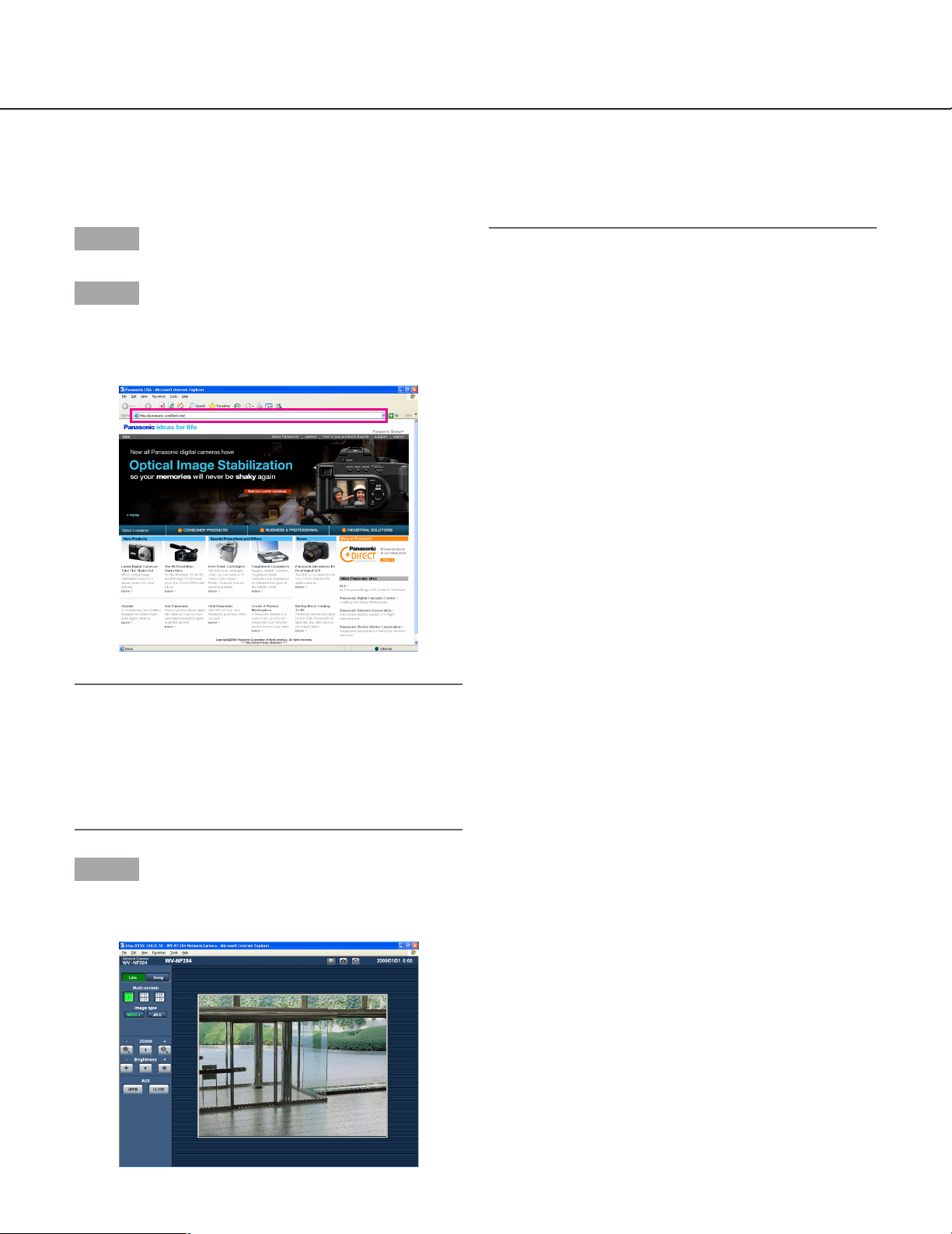
Step 1
Start up the web browser.
Step 2
Enter the IP address designated using the Panasonic IP
setup software in the address box of the browser.
Example: http://192.168.0.10/
Important:
• When the HTTP port number is changed from "80",
enter "http://IP address of the camera +: (colon) +
port number" in the address box of the browser, for
example, "http://192.168.0.11:8080".
• Configure the web browser to not use the proxy
server.
Step 3
Press the [Enter] key on the keyboard.
→ The "Live" page will be displayed.
Notes:
• When "ON" is selected for "User Authentication"
(☞ page 34), the authentication window will be displayed before displaying live images for the user
name and password entries. The default user name
and password are as follows.
User name: admin
Password: 12345
When accessing the camera without changing the
default password, the pop-up window saying that it
is recommended to change the password will be displayed.
To enhance the security, change the password for
the user "admin". It is recommended to change this
password periodically.
• Maximum concurrent access to the camera will be
limited to up to 8 users in the following case.
• When "Unicast port (AUTO)" is selected for
"Transmission type" (☞ page 22)
• When "Unicast port (MANUAL)" is selected for
"Transmission type" (☞ page 22)
• When JPEG images are being transmitted from
the camera
Depending on the set values for "Total bit rate" and
"Max bit rate (per 1 client)", the maximum concurrent
access number may be less than 8 users. When 8
users have been concurrently accessing already, the
access limit message will be displayed for users who
accessed subsequently.
• When "ON" is selected for "MPEG-4 transmission"
(☞ page 22), an MPEG-4 image will be displayed.
When "OFF" is selected, a JPEG image will be displayed. It is possible to display JPEG image even
when "ON" is selected for "MPEG-4 transmission".
In this case, the refresh interval will be limited.
<Refresh interval (JPEG)>
• When "ON" is selected for "MPEG-4 transmission"
JPEG (VGA): 5 fps
JPEG (QVGA): 10 fps
• When "OFF" is selected for "MPEG-4 transmission"
JPEG (VGA or QVGA): 30 fps
The refresh interval may be longer depending on a network environment, PC spec, photographic subject,
access traffic, etc.
4
Important:
• When displaying multiple MPEG-4 images on a PC,
images may not be displayed depending on the performance of the PC.
• When "ON" is selected for "VMD alarm" (☞ page
27), the frame rate of MPEG-4 images will become
15 fps at a maximum.
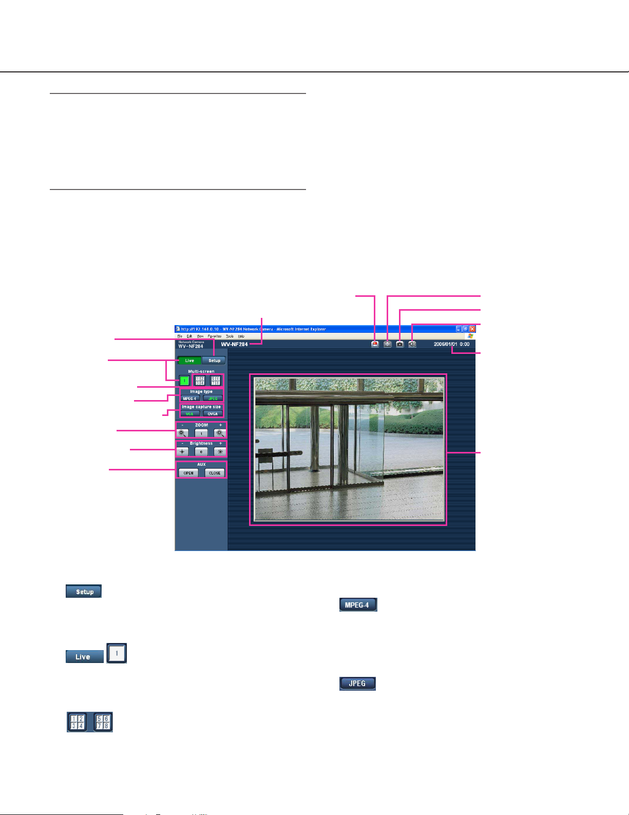
About the "Live" page
Refer to this page for further information about the
"Live" page.
!0 Alarm occurrence indication button
o Camera name
q [Setup] button
w [Live] button
e Multi-screen buttons
r Image type buttons
t Image capture size buttons
y ZOOM buttons
u Brightness buttons
i AUX buttons
q [Setup] button (*1)
Click this button to display the setup menu. The button will turn green and the setup menu will be displayed.
w [Live] button
Click this button to display the "Live" page. The button will turn green and the "Live" page will be displayed.
!1 Full screen button
!2 One shot button
!3 Audio button
!4 Time and date
!5 Main area
r Image type buttons
: The letters "MPEG-4" on the button will
turn green and an MPEG-4 image will be
displayed. When "OFF" is selected for
"MPEG-4 transmission" on the setup
menu, the [MPEG-4] button will not be displayed. (☞ page 22)
: The letters "JPEG" on the button will turn
green and JPEG image will be displayed.
e Multi-screen buttons
Images from multiple cameras can be displayed on
a multi-screen by registering cameras on the setup
menu. (☞ page 7)
5
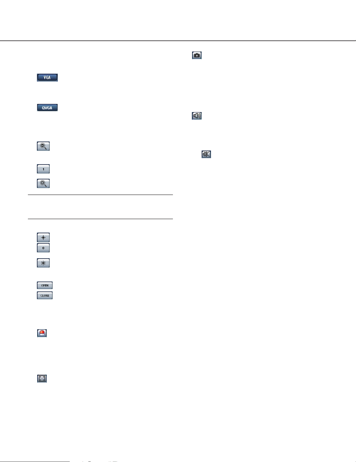
t Image capture size buttons
These buttons will be displayed only when a JPEG
image is displayed.
: The letters "VGA" on the button will turn
green and images will be displayed in VGA
size.
: The letters "QVGA" on the button will turn
green and images will be displayed in
QVGA size.
y ZOOM buttons (*2)
: The zoomed image will be zoomed out.
(Image displayed in the original size cannot be
zoomed out.)
: The zoomed image will return to the original
size.
: The displayed image will be zoomed in.
!2 One shot button
Click this button to take a picture (a still picture). The
picture will be displayed on a newly opened window.
When right-clicking on the displayed image, the popup menu will be displayed. The displayed image can
be saved on the PC by selecting "Save" from the
pop-up menu.
!3 Audio button
The [Audio] button will be displayed only when "ON"
is selected for "Mic mode" on the setup menu.
(☞ page 25)
When this button is clicked, the button will turn into
the button and audio will not be heard.
!4 Time and date
Current time will be displayed in the set date/time
display format (☞ page 17).
Note:
When "ON" is selected for "VMD alarm" (☞ page
27), the displayed images will not be zoomed in.
u Brightness buttons (*2)
: The displayed image will be darker.
: The adjusted brightness will return to the
default brightness. (☞ page 24)
: The displayed image will be brighter.
i AUX buttons (*2)
: The AUX connector will open.
: The AUX connector will close.
o Camera name
The set camera name will be displayed.
!0 Alarm occurrence indication button (*2)
This button will be displayed and will blink when an
alarm occurred. When the button is clicked, the button will disappear and the alarm output connector
will be reset. (☞ page 29)
!5 Main area
Images from the camera will be displayed in this
area.
*1 Operable by only users whose access level is "1.
Administrator"
*2 Only operable by users whose access level is "1.
Administrator" or "2. Camera control" when "ON" is
selected for "User authentication" (☞ page 34).
Refer to page 34 for further information about the
access level.
!1 Full screen button
Images will be displayed on a full screen. To return
to the "Live" page, press the [Esc] key or the [F5]
key, or the combination of the [Alt] key and the [F4]
key on the keyboard.
6
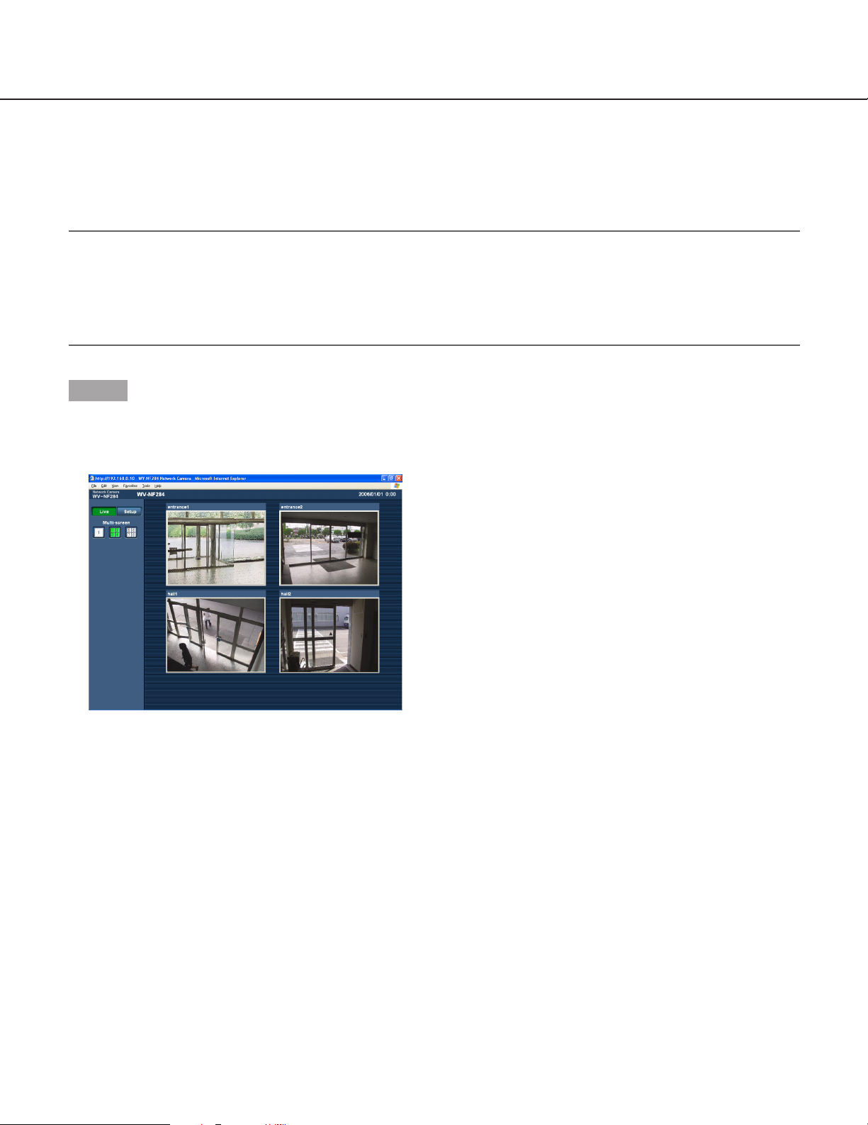
Monitor images from multiple cameras
Images from multiple cameras can be displayed on a multi-screen. Images from up to 4 cameras can be displayed
simultaneously. To display images on a multi-screen, it is necessary to register cameras in advance. 4 cameras can
be registered as a group and up to 2 groups (8 cameras) can be registered. (☞ page 26)
Important:
• Select "OFF" for both the user authentication and the host authentication of the camera to be registered.
(☞ pages 34 and 35)
• Only JPEG images can be displayed on a multi-screen. Audio will not be heard.
• When the power is turned off or the LAN cable is disconnected while displaying images, displaying images on a
multi-screen from the "Live" page will become unavailable.
Step 1
Click the [Multi-screen] button.
→ Images from the registered cameras will be dis-
played on a 4-split screen.
q To display images on a single screen, click the [Live]
button.
w Click a camera title. Live images from the camera
corresponding to the clicked camera title will be displayed on the "Live" page of the newly opened window.
7

Action at an Alarm Occurrence
The alarm action will be performed when the following alarm occur.
Alarm type
Terminal alarm: When connecting an alarm device such as a sensor to the alarm connector on the mounting
side of the camera, the alarm action will be performed when the connected alarm device activated.
VMD alarm: When a motion is detected in the set VMD area, the alarm action will be performed.
* VMD stands for "Video Motion Detection".
Command alarm: When a Panasonic alarm protocol (☞ page 27) is received from the connected device via a
network, the alarm action will be performed.
Action at an Alarm Occurrence
Display the [Alarm occurrence indication] button on the "Live" page (☞ page 5)
The [Alarm occurrence indication] button will be displayed on the "Live" page at an alarm occurrence.
Note:
The [Alarm occurrence indication] button will be refreshed in 30 seconds intervals. For this reason, it may take a
maximum of 30 seconds until the [Alarm occurrence indication] button is displayed on the "Live" page at an alarm
occurrence.
Notify of alarm occurrences to the device connected to the alarm connector
It is possible to output signals from the alarm connector on the mounting side of the camera and sound the buzzer
when an alarm occurs. The settings for the alarm output can be configured on the [Alarm] tab of the "Alarm setup"
page. (☞ page 29)
Transmit an image onto a server automatically
An alarm image can be transmitted at an alarm occurrence to the server designated in advance.
The settings required to transmit an alarm image to a server can be configured in the "Alarm image setup" section of
the [Alarm] tab of the "Alarm setup" page (☞ page 28) and the [FTP] tab of the "Server setup" page (☞ page 37).
Notify of alarm occurrences by e-mail
Alarm mail (alarm occurrence notification) can be sent at an alarm occurrence to the e-mail addresses registered in
advance. Up to 4 addresses can be registered as recipients of the alarm mail. An alarm image (still picture) can be
sent with the alarm mail as an attached file. The settings for alarm mail can be configured in the "E-mail notification
setup" section of the [Notification] tab of the "Alarm setup" page (☞ page 32) and the [Mail] tab of the "Server setup"
page (☞ page 36).
Notify of alarm occurrences to the designated IP addresses (Panasonic alarm protocol)
This function is available only when Panasonic device, such as the network disk recorder, is connected to the system. When "ON" is selected for "Panasonic alarm protocol", the connected Panasonic device will be notified that the
camera is in the alarm state. The settings for Panasonic alarm protocol can be configured on the [Notification] tab of
the "Alarm setup" page. (☞ page 33)
8

Transmit Images onto an FTP Server
Images can be transmitted to an FTP server. By configuring the following settings, transmission of images captured
at an alarm occurrence or captured at a designated interval to an FTP server will become available.
Important:
When using this function, set the user name and password to restrict users who can log into the FTP server.
Transmit an alarm image at an alarm occurrence (Alarm image FTP transmission)
An alarm image can be transmitted at an alarm occurrence to the FTP server. To transmit alarm images to an FTP
server, it is necessary to configure the settings in advance.
The settings for the FTP server can be configured on the [FTP] tab of the "Server setup" page. (☞ page 37)
The alarm image FTP transmission function can be turned on/off on the [Alarm] tab of the "Alarm setup" page.
(☞ page 28)
Note:
Depending on the network traffic, number of the transmitted images may not reach the set number of images to
be transmitted.
Transmit images at a designated interval or period (FTP periodic transmission)
Images can be transmitted at a designated interval or period. To transmit images at a designate interval or period, it
is necessary to configure the settings in advance.
The settings for the FTP server to which images are to be transmitted can be configured on the [FTP] tab of the
"Server setup" page. (☞ page 37)
On the [FTP] tab of the "Network setup" page, the FTP periodic transmission function can be turned on/off, and the
settings relating to schedules (periods) can be configured. (☞ page 43 - 45)
Notes:
• Depending on the network line speed or the network traffic, images may not be transmitted at the exact designated interval or period.
• When "ON" is selected for both of the alarm image FTP transmission function and the FTP periodic transmission
function, the alarm image FTP transmission function will be given priority over the FTP periodic transmission
function. For this reason, images may not be transmitted at the exact designated interval or period if alarms
occur frequently.
9

Save images on the SD memory card when failed to transmit images by the FTP periodic transmission function
Images that have failed to transmit using the FTP periodic transmission can be saved automatically on the SD memory card. To obtain the images saved on the SD memory card, use the Windows command prompt or FTP client
software. The obtained images can be browsed on a PC.
* When using the "SD memory REC" function of a Panasonic’s network disk recorder, select "OFF" for the "FTP
periodic transmission" function. (☞ page 43)
* When using the DHCP function, images will not be saved on the SD memory card until an IP address is assigned
to the camera.
* We make no guarantee for any damages of files on the SD memory card incurred by malfunction or error occur-
rence in files saved on the SD memory card regardless of what the cause may be.
Save images on the SD memory card
By configuring the following settings, saving images which had been failed to transmit to the FTP server using the
FTP periodic transmission function will become available.
About SD memory card: Use (☞ page 19)
File name: With time and date (☞ page 43)
Obtain images on the SD memory card
Step 1
Access the camera using the Windows command prompt or FTP client software.
→ The window with the user name and password entry fields will be displayed.
Step 2
Enter the user name whose access level is "1. Administrator" and its password.
→ Log in the camera.
Note:
The default user name with the access level "1. Administrator" and its password are as follows.
User name: admin
Password: 12345
To enhance the security, it is recommended to change the password for the administrator periodically.
10
Step 3
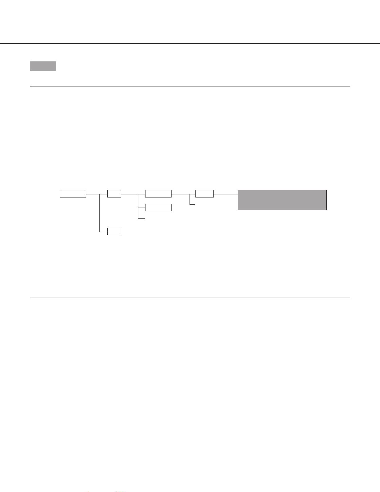
Move the current directory to drive B and obtain images.
Notes:
• When logging in the camera, the current directory will be drive D. Images on the SD memory card can be found
in the "FTP" directory under drive B. Move to the "FTP" directory and obtain images.
<Directory structure of drive B>
Example: To obtain the image (img_06010101230000.jpg) using the Windows command prompt
q Enter "c:\>ftp 192.168.0.10" and press the [Enter] key.
→ FTP connection will be established with "192.168.0.10".
w Log in by entering the user name and the password.
e Enter "ftp>cd B:\FTP\060101\0123" and press the [Enter] key.
→ The current directory will be "B:\FTP\060101\0123".
Directory
Drive B FTP
:
:
:
:
LOG
Directory
(year/month/day)
060101
060102
:
:
← Destination of logs to be saved
Directory
(hour/minute)
0123
:
:
An image failed to transmit by the FTP
periodic transmission function
(Example) img_06010101230000.jpg
↑ The image will be saved here.
r The transfer mode will be set to the binary mode. Enter "ftp>bin" and press the [Enter] key.
t Enter "ftp> get img_06010101230000.jpg" and press the [Enter] key.
→ The image will be obtained.
y Log out by entering "ftp>bye" and press the [Enter] key.
• It is possible to delete images on the SD memory card using the Windows command prompt, etc.
11

About the network security of this unit
Equipped security functions
The following security functions are featured in this camera.
q Access restrictions by the host authentication and the user authentication
It is possible to restrict users from accessing the camera by setting the host authentication and/or the user
authentication to on. (☞ pages 34 and 35)
w Access restrictions by changing the HTTP port
It is possible to prevent illegal access such as port scanning, etc. by changing the HTTP port number.
(☞ page 39)
Note:
When failed to pass the user authentication (authentication error) using the same IP address (PC) for 8 times
within 5 minutes, access to the camera will be denied for a while.
Important:
Design and enhance security countermeasures to prevent leakage of information such as image data, authentication information (user name and password), alarm mail information, FTP server information, DDNS server
information, etc.
12
Display the Setup Menu and Configure the Settings of the Camera using a PC
The settings of the camera can be configured on the setup menu.
The setup menu is only operable by users whose access level is "1. Administrator".
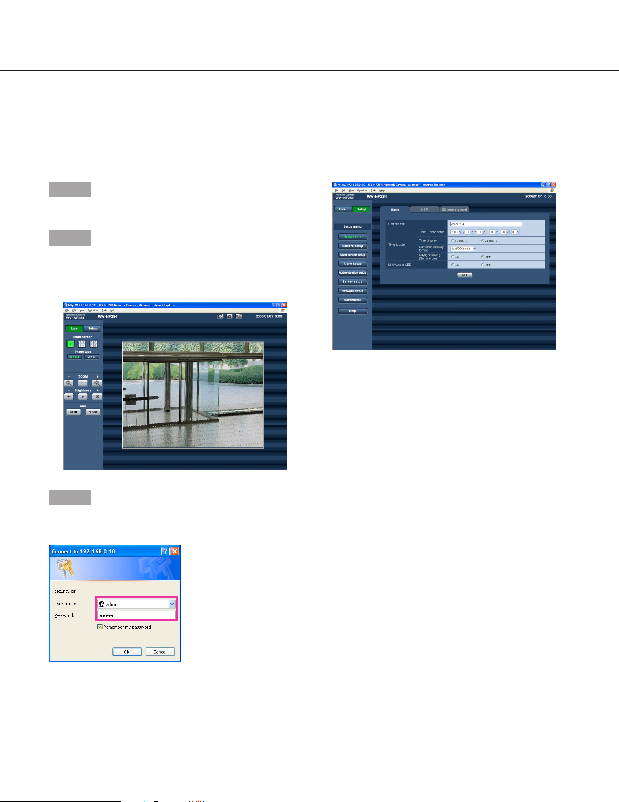
How to display the setup menu
Step 1
Display the "Live" page (☞ page 4).
Step 2
Click the [Setup] button on the "Live" page.
→ The window with the user name and password entry
fields will be displayed.
Step 3
Click the [OK] button after entering the user name and
the password.
→ Click this button to display the setup menu.
Refer to the next page for further information about
this menu.
13

How to operate the setup menu
Important:
When there are two [SET] buttons (or [REG] buttons) or more on the page, click the respective button to the edited setting item.
<Example>
A
Menu button Setup page
Step 1
Click the desired button in the frame on the left of the
window to display the respective setup menu.
When there are tabs at the top of the setup page displayed in the frame on the right of the window, click the
desired tab to display and configure the setting items
relating to the name of the tab.
Step 2
Complete each setting item displayed in the frame on
the right of the window.
Step 3
After completing each setting item, click the [SET] button (or [REG] button) to apply them.
A-1
B
B-1
When completing the setting items in field A, click
the [SET] button below field A (A-1). The edited setting items in field A will not be applied unless the
[SET] button below field A (A-1) is clicked.
In the same manner as above, click the [SET] button
below field B (B-1) when completing the setting
items in field B.
14
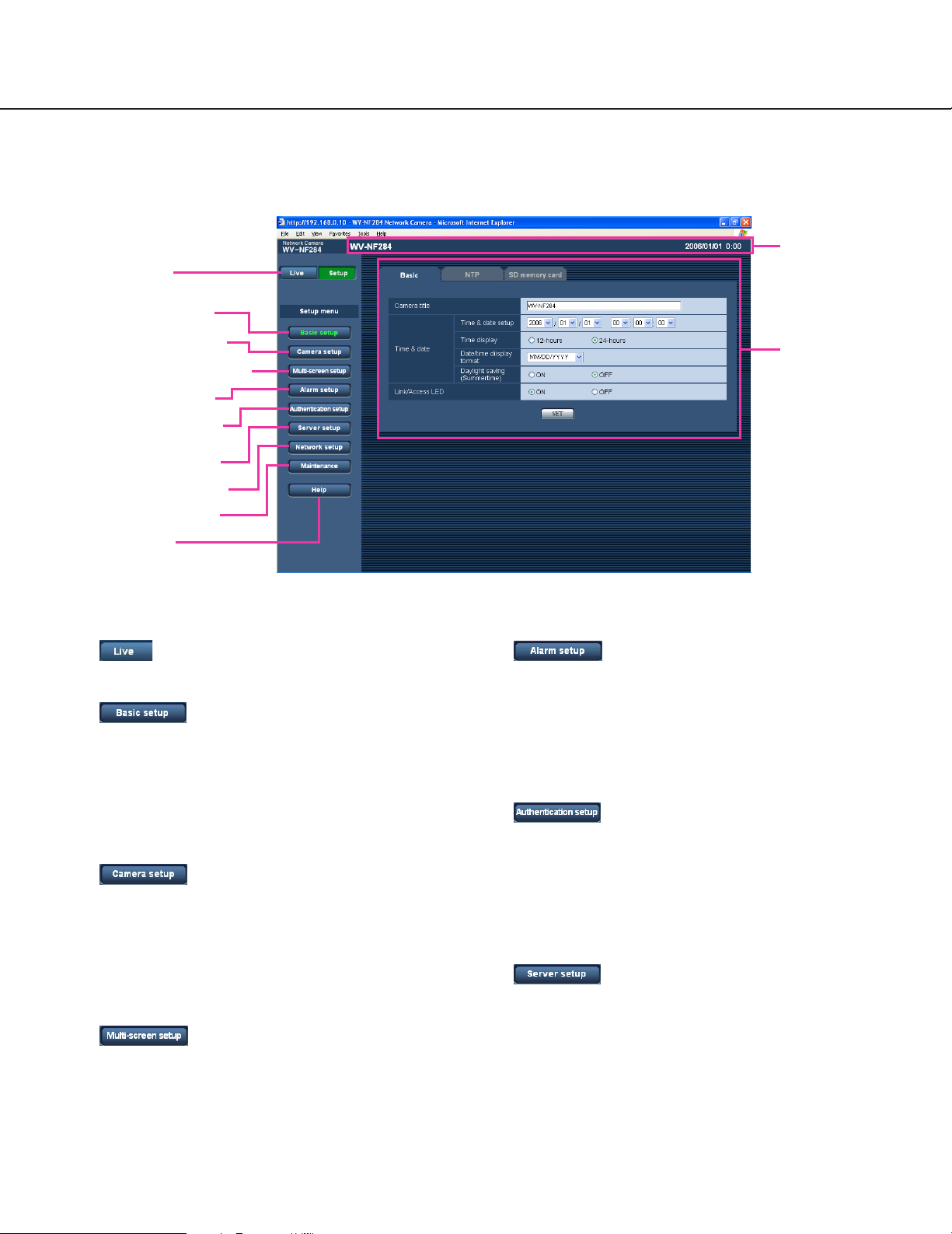
About the operation window
q [Live] button
w [Basic setup] button
!1 Status display
area
e [Camera setup] button
r [Multi-screen setup] button
t [Alarm setup] button
y [Authentication setup]
button
u [Server setup] button
i [Network setup] button
o [Maintenance] button
!0 [Help] button
q [Live] button
The "Live" page will be displayed.
w [Basic setup] button
Click this button to display the "Basic setup" page.
The basic settings such as time and date and camera name, and the settings relating to the NTP server and the SD memory card can be configured on
the "Basic setup" page. Refer to page 17 for further
information.
e [Camera setup] button
Click this button to display the "Camera setup" page.
The settings relating to image from the camera such
as image quality and brightness, and the settings
relating to audio can be configured on the "Camera
setup" page. Refer to page 21 for further information.
r [Multi-screen setup] button
Click this button to display the "Multi-screen setup"
page. The cameras to be used for the multi-screen
display can be registered on the "Multi-screen setup"
page. Refer to page 26 for further information.
!2 Setup page
t [Alarm setup] button
Click this button to display the "Alarm setup" page.
The settings relating to alarm occurrences such as
settings for the alarm action at an alarm occurrence,
the alarm occurrence notification, and the VMD area
settings can be configured on the "Alarm setup"
page. Refer to page 27 for further information.
y [Authentication setup] button
Click this button to display the "Authentication setup"
page. The settings relating to the authentication
such as users and PCs restrictions for accessing the
camera can be configured on the "Authentication
setup" page. Refer to page 34 for further information.
u [Server setup] button
Click this button to display the "Server setup" page.
The settings relating to the mail server and the FTP
server to which the camera accesses can be configured on the "Server setup" page. Refer to page 36
for further information.
15
i [Network setup] button
Click this button to display the "Network setup" page.
The network settings and the settings relating to
DDNS (Dynamic DNS), SNMP (Simple Network
management Protocol) and FTP (File Transfer
Protocol) can be configured on the "Network setup"
page. Refer to page 38 for further information.
o [Maintenance] button
Click this button to display the "Maintenance" page.
System log check, firmware upgrade and initialization of the setup menu can be performed on the
"Maintenance" page. Refer to page 46 for further
information.
!0 [Help] button
Click this button to display the "Help" page.
!1 Status display area
The name of the camera whose settings currently
being configured, and date and time will be displayed.
!2 Setup page
Pages of each setup menu will be displayed. There
are tabs for some setup menus.
16
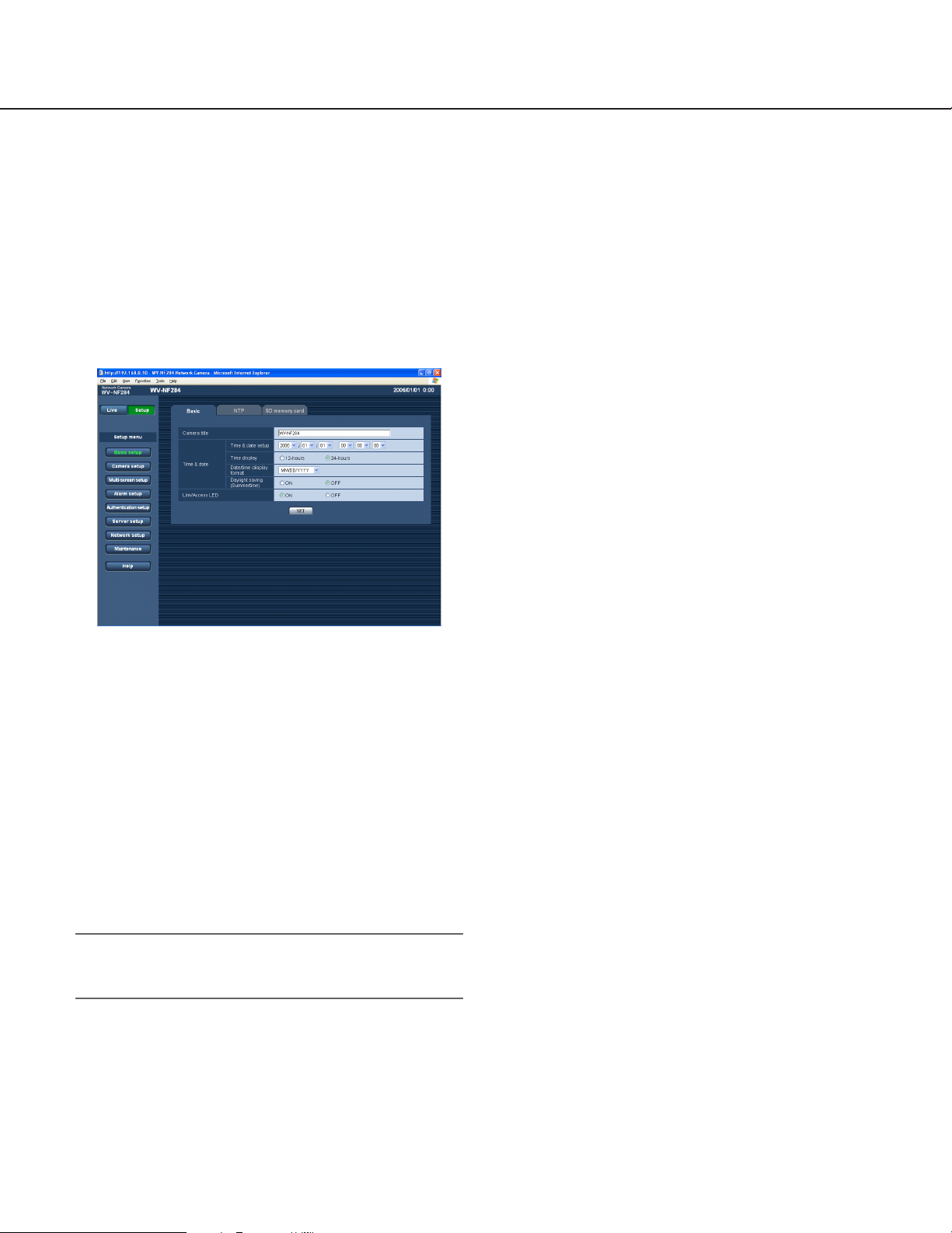
Configure the basic settings of the camera [Basic setup]
The basic settings such as time and date and camera name, and the settings relating to the NTP server and the SD
memory card can be configured on the "Basic setup" page.
The "Basic setup" page has 3 tabs of the [Basic] tab, the [NTP] tab and the [SD memory card] tab.
Configure the basic settings [Basic]
Click the [Basic] tab on the "Basic setup" page. (☞ page 15)
The settings such as the camera name, time and date, etc. can be configured on this page.
[Date/time display format]
Select a date/time display format.
When "04/01/2006 13:10:00" is set for "Time and date
setup" after selecting "24-hours" for "Time display", time
and date will be displayed as follows respectively.
DD/MM/YYYY: 01/04/2006 13:10
MM/DD/YYYY: 04/01/2006 13:10
DD/Mmm/YYYY: 01/Apr/2006 13:10
YYYY/MM/DD: 2006/04/01 13:10
Mmm/DD/YYYY: Apr/01/2006 13:10
Default setting: MM/DD/YYYY
[Camera title]
Enter the title of the camera. Click the [SET] button after
entering the title of the camera. The entered title will be
displayed in the status display area.
Number of characters for the camera title: 0 - 20
characters
Default setting: WV-NF284
[Time and date setup]
Enter the current time and date. When "12-hours" is
selected for "Time display", "AM" or "PM" can be selected.
Available value: 2006/01/01 00:00:00 -
2035/12/31 23:59:59
Note:
"2036/01/01 00:00:00" or later is unavailable to set
and display.
[Time display]
Select "12-hours" or "24-hours". Enter the current hour
reflecting this setting when entering the current time and
date for "Time and date setup".
Default setting: 24 hours
[Daylight saving (Summertime)]
Select "ON" or "OFF" to determine whether or not to
apply daylight saving time. Select "ON" or "OFF" to
determine whether or not to apply daylight saving time.
ON: Applies summer time. An asterisk (*) will be dis-
played on the left side of the displayed time and
date.
OFF: Does not apply summer time.
Default setting: OFF
[Link/Access LED]
Select "ON" or "OFF" to determine whether or not to
light the link indicator, the access indicator, and the SD
memory card error indicator. Select "ON" to check the
network status by lighting the indicators. Select "OFF" to
turn off the indicators at all times.
• Even when "ON" is selected, the link indicator and
the access indicator inside the dome cover will not
light when the indicators ON/OFF switch on the
camera is set to "OFF".
Default setting: ON
17
 Loading...