

Page 1

Video Monitor
Operating Instructions
Model No. WV-LC1710
ENGLISH
FRANÇAIS
please read these instructions carefully and save this manual for future use.
Before attempting to connect or operate this product,
Page 2
ENGLISH VERSION
Caution:
Before attempting to connect or operate this product, please
read the label on the rear.
CAUTION
RISK OF ELECTRIC SHOCK
DO NOT OPEN
CAUTION: TO REDUCE THE RISK OF ELECTRIC SHOCK
DO NOT REMOVE COVER
NO USER-SERVICEABLE PARTS INSIDE
REFER SERVICING TO QUALIFIED PERSONNEL.
The lightning flash with arrowhead
symbol, within an equilateral triangle, is
intended to alert the user to the presence of uninsulated “dangerous voltage”
within the product’s enclosure that may
SA 1965
SA 1966
be of sufficient magnitude to constitute
a risk of electric shock to persons.
The exclamation point within an equilateral triangle is intended to alert the user
to the presence of important operating
and maintenance (servicing) instructions in the literature accompanying the
appliance.
Power disconnection. Unit with or
without ON-OFF switches have power
supplied to the unit whenever the power
cord is inserted into the power source;
however, the unit is operational only
when the ON-OFF switch is in the ON
position. The power cord is the main
power disconnected for all units.
NOTE: This equipment has been tested and found to com-
For U.S.A
ply with the limits for a Class A digital device, pursuant to
Part 15 of the FCC Rules. These limits are designed to
provide reasonable protection against harmful interference
when the equipment is operated in a commercial environment. This equipment generates, uses, and can radiate
radio frequency energy and, if not installed and used in accordance with the instruction manual, may cause harmful
interference to radio communications.
Operations of this equipment in a residential area is likely
to cause harmful interference in which case the user will be
required to correct the interference at his own expense.
FCC Caution: To assure continued compliance, (example
- use only shielded interface cables when connecting to
computer or pheripheral devices). Any changes or modifications not expressly approved by the party responsible
for compliance could void the user’s authority to operate
this equipment.
For Canada
This Class A digital apparatus complies with Canadian
ICES-003.
Cet appareil numérique de la classe A est conforme
à la norme NMB-003 du Canada.
The serial number of this product may be found on the rear
of the unit.
You should note the serial number of this unit in the space
provided and retain this book as a permanent record of
your purchase to aid identification in the event of theft.
Model No. WV-LC1710
Serial No.
WARNING: • This apparatus must be earthed.
• To reduce the risk of fire or electric shock, do not expose this appliance to rain or moisture. The apparatus shall
not be exposed to dripping or splashing and that no objects filled with liquids, such as vases, shall be placed on
the apparatus.
2
Page 3

IMPORTANT SAFETY INSTRUCTIONS
1) Read these instructions.
2) Keep these instructions.
3) Heed all warnings.
4) Follow all instructions.
5) Do not use this apparatus near water.
6) Clean only with dry cloth.
7) Do not block any ventilation openings. Install in accordance with the manufacturer’s instructions.
8) Do not install near any heat sources such as radiators, heat registers, stoves, or other apparatus (including amplifiers) that produce
heat.
9) Do not defeat the safety purpose of the polarized or grounding type plug. A polarized plug has two blades with one wider than the other.
A grounding type plug has two blades and a third grounding prong. The wide blade or the third prong are provided for your safety. If the
provided plug does not fit into your outlet, consult an electrician for replacement of the obsolete outlet.
10) Protect the power cord from being walked on or pinched particularly at plugs, convenience receptacles, and the point where they exit from
the apparatus.
ENGLISH
11) Only use attachments/accessories specified by the manufacturer.
12) Use only with the cart, stand, tripod, bracket, or table specified by the manufacturer, or sold with the apparatus. When a cart is used, use
caution when moving the cart/apparatus combination to avoid injury from tip-over.
S3125A
13) Unplug this apparatus during lightning storms or when unused for long periods of time.
14) Refer all servicing to qualified service personnel. Servicing is required when the apparatus has been damaged in any way, such as powersupply cord or plug is damaged, liquid has been spilled or objects have fallen into the apparatus, the apparatus has been exposed to rain
or moisture, does not operate normally, or has been dropped.
3
Page 4

LIMITATION OF LIABILITY
THIS PUBLICATION IS PROVIDE “AS IS” WITHOUT WARRANTY OF ANY KIND, EITHER EXPRESS OR IMPLIED,
INCLUDING BUT NOT LIMITED TO, THE IMPLIED WARRANTIES OF MERCHANTABILITY, FITNESS FOR ANY PARTICULAR PURPOSE, OR NON-INFRINGEMENT OF THE THIRD
PARTY’S RIGHT.
DISCLAIMER OF WARRANTY
IN NO EVENT SHALL MATSUSHITA ELECTRIC INDUSTRIAL CO., LTD. BE LIABLE TO ANY PARTY OR ANY PERSON,
EXCEPT FOR REPLACEMENT OR REASONABLE MAINTENANCE OF THE PRODUCT, FOR THE CASES, INCLUDING
BUT NOT LIMITED TO BELOW:
1) ANY DAMAGE AND LOSS, INCLUDING WITHOUT LIMITATION, DIRECT OR INDIRECT, SPECIAL CONSEQUENTIAL OR EXEMPLARY, ARISING OUT OF OR RELATING
TO THE PRODUCT;
THIS PUBLICATION COULD INCLUDE TECHNICAL INACCURACIES OR TYPOGRAPHICAL ERRORS. CHANGES ARE
ADDED TO THE INFORMATION HEREIN, AT ANY TIME, FOR
THE IMPROVEMENTS OF THIS PUBLICATION AND/OR THE
CORRESPONDING PRODUCT(S).
2) PERSONAL INJURY OR ANY DAMAGE CAUSED BY
INAPPROPRIATE USE OR NEGLIGENT OPERATION OF
THE USER;
3) UNAUTHORIZED DISASSEMBLE, REPAIR OR MODIFICATION OF THE PRODUCT BY THE USER;
4) ANY PROBLEM, CONSEQUENTIAL INCONVENIENCE,
OR LOSS OR DAMAGE, ARISING OUT OF THE SYSTEM
COMBINED BY THE DEVICES OF THIRD PARTY.
4
Page 5

CONTENTS
IMPORTANT SAFETY INSTRUCTIONS . . . . . . . . . . . . . . . . . . . . . . . . . . . . . . . . . . . . . . . . . . . . . . . . . . . . . . . . . . . 3
LIMITATION OF LIABILITY. . . . . . . . . . . . . . . . . . . . . . . . . . . . . . . . . . . . . . . . . . . . . . . . . . . . . . . . . . . . . . . . . . . . . . 4
DISCLAIMER OF WARRANTY . . . . . . . . . . . . . . . . . . . . . . . . . . . . . . . . . . . . . . . . . . . . . . . . . . . . . . . . . . . . . . . . . . 4
PREFACE. . . . . . . . . . . . . . . . . . . . . . . . . . . . . . . . . . . . . . . . . . . . . . . . . . . . . . . . . . . . . . . . . . . . . . . . . . . . . . . . . . . 6
FEATURES. . . . . . . . . . . . . . . . . . . . . . . . . . . . . . . . . . . . . . . . . . . . . . . . . . . . . . . . . . . . . . . . . . . . . . . . . . . . . . . . . . 6
PRECAUTIONS . . . . . . . . . . . . . . . . . . . . . . . . . . . . . . . . . . . . . . . . . . . . . . . . . . . . . . . . . . . . . . . . . . . . . . . . . . . . . . 6
MAJOR OPERATING CONTROLS AND THEIR FUNCTIONS . . . . . . . . . . . . . . . . . . . . . . . . . . . . . . . . . . . . . . . . . . 7
Front View . . . . . . . . . . . . . . . . . . . . . . . . . . . . . . . . . . . . . . . . . . . . . . . . . . . . . . . . . . . . . . . . . . . . . . . . . . . . . . 7
Rear View . . . . . . . . . . . . . . . . . . . . . . . . . . . . . . . . . . . . . . . . . . . . . . . . . . . . . . . . . . . . . . . . . . . . . . . . . . . . . . 7
INSTALLATION. . . . . . . . . . . . . . . . . . . . . . . . . . . . . . . . . . . . . . . . . . . . . . . . . . . . . . . . . . . . . . . . . . . . . . . . . . . . . . . 9
Removing Stand in the Monitor . . . . . . . . . . . . . . . . . . . . . . . . . . . . . . . . . . . . . . . . . . . . . . . . . . . . . . . . . . . . . .9
Mounting into the Rack . . . . . . . . . . . . . . . . . . . . . . . . . . . . . . . . . . . . . . . . . . . . . . . . . . . . . . . . . . . . . . . . . . . . 9
Mounting on the Wall. . . . . . . . . . . . . . . . . . . . . . . . . . . . . . . . . . . . . . . . . . . . . . . . . . . . . . . . . . . . . . . . . . . . . 10
CONNECTIONS. . . . . . . . . . . . . . . . . . . . . . . . . . . . . . . . . . . . . . . . . . . . . . . . . . . . . . . . . . . . . . . . . . . . . . . . . . . . . 11
Connection with the Camera Site . . . . . . . . . . . . . . . . . . . . . . . . . . . . . . . . . . . . . . . . . . . . . . . . . . . . . . . . . . . 12
Multiple Monitor Connection . . . . . . . . . . . . . . . . . . . . . . . . . . . . . . . . . . . . . . . . . . . . . . . . . . . . . . . . . . . . . . . 12
Connection with the Digital Disk Recorder . . . . . . . . . . . . . . . . . . . . . . . . . . . . . . . . . . . . . . . . . . . . . . . . . . . . 12
Connection with PC. . . . . . . . . . . . . . . . . . . . . . . . . . . . . . . . . . . . . . . . . . . . . . . . . . . . . . . . . . . . . . . . . . . . . . 12
Connection with DVD. . . . . . . . . . . . . . . . . . . . . . . . . . . . . . . . . . . . . . . . . . . . . . . . . . . . . . . . . . . . . . . . . . . . . 12
STARTUP. . . . . . . . . . . . . . . . . . . . . . . . . . . . . . . . . . . . . . . . . . . . . . . . . . . . . . . . . . . . . . . . . . . . . . . . . . . . . . . . . . 13
AUDIO VOLUME CONTROL . . . . . . . . . . . . . . . . . . . . . . . . . . . . . . . . . . . . . . . . . . . . . . . . . . . . . . . . . . . . . . . . . . . 14
DISPLAYING VIDEO ADJUSTMENT MENU . . . . . . . . . . . . . . . . . . . . . . . . . . . . . . . . . . . . . . . . . . . . . . . . . . . . . . . 15
Displaying Video Adjustment Menu . . . . . . . . . . . . . . . . . . . . . . . . . . . . . . . . . . . . . . . . . . . . . . . . . . . . . . . . . . 15
Setting of Composite Video / S-Video / Component Video Input . . . . . . . . . . . . . . . . . . . . . . . . . . . . . . . . . . . 16
Setting of PC Input . . . . . . . . . . . . . . . . . . . . . . . . . . . . . . . . . . . . . . . . . . . . . . . . . . . . . . . . . . . . . . . . . . . . . . 18
Picture-in-Picture Mode Monitoring . . . . . . . . . . . . . . . . . . . . . . . . . . . . . . . . . . . . . . . . . . . . . . . . . . . . . . . . . . 19
TROUBLESHOOTING . . . . . . . . . . . . . . . . . . . . . . . . . . . . . . . . . . . . . . . . . . . . . . . . . . . . . . . . . . . . . . . . . . . . . . . . 20
SPECIFICATIONS . . . . . . . . . . . . . . . . . . . . . . . . . . . . . . . . . . . . . . . . . . . . . . . . . . . . . . . . . . . . . . . . . . . . . . . . . . . 21
Video Monitor. . . . . . . . . . . . . . . . . . . . . . . . . . . . . . . . . . . . . . . . . . . . . . . . . . . . . . . . . . . . . . . . . . . . . . . . . . . 21
AC Adapter . . . . . . . . . . . . . . . . . . . . . . . . . . . . . . . . . . . . . . . . . . . . . . . . . . . . . . . . . . . . . . . . . . . . . . . . . . . . 22
STANDARD ACCESSORIES . . . . . . . . . . . . . . . . . . . . . . . . . . . . . . . . . . . . . . . . . . . . . . . . . . . . . . . . . . . . . . . . . . . 22
5
Page 6

PREFACE
This monitor is a 17" type LCD Monitor, using a motion adaption IP
conversion circuit and Y/C separation circuit for high definition and
high resolution of picture display.
FEATURES
• Built-in high resolution (SXGA) panel with high contrast ratio,
wide view angle and true 8 bit full color.
• Selectable inputs, including Composite Video, S-Video,
Component Video and analog RGB signal input for personal
computer (PC).
• Automatically switchable NTSC and PAL system.
• PC display capacity which can support VGA (640 × 480) ~ SXGA
(1280 × 1024) resolutions. Picture size and position can be automatically adjusted.
• One audio input and output with built in maximum speaker output
of 0.5 W.
PRECAUTIONS
• Refer all work related to the installation of this product to
qualified personnel or system installers.
• Do not block the ventilation slots on the cover.
To prevent the appliance from overheating, place it at least 5 cm
{2 inches} away from the wall.
• Do not drop metallic parts through the slots.
This could permanently damage the appliance. Turn the power off
immediately and contact qualified service personnel for service.
• Do not attempt to disassemble the appliance.
To prevent electric shock, do not remove screws or covers. There
are no user-serviceable parts inside. Contact qualified service
personnel for maintenance.
• Handle the appliance with care.
Do not strike or shake it, as this may damage the appliance.
• Onscreen setup menu.
• Auto-volt power supply from 100 V AC ~ 240 V AC (AC Adapter).
Note: The included AC power cord is for 120 V AC only. It is
necessary to change the AC power cord when using other power
supply other than 120 V AC.
• Metal cabinet casing. It can be mounted in an EIA standard rack
using an optional rack mount bracket.
• The mounting holes for wall mount located on the rear side
of the monitor comply with VESA standard. It can be mounted in the wall by installing a commercialized wall mount.
VESA: Video Electronics Standards Association
•
Do not operate the appliance beyond its specified temperature, humidity or power source ratings.
Use the appliance at temperatures within 0 °C ~ +40 °C {32 °F ~
104 °F} and humidity below 90 %.
The input power source for this appliance is 100 V AC to 240 V
AC, 50/60 Hz with AC Adapter.
Do not use strong or abrasive detergents when cleaning
•
the appliance body.
Use a dry cloth to clean the appliance when it is dirty. When
the dirt is hard to remove, use a mild detergent and wipe gently.
Afterwards, wipe the remained part of the detergent in it with
a dry cloth.
• The surface of the display panel is applied by special
coating.
Do not point hard objects and wipe by abrasive material. It can
cause scratches and damages on the display panel.
• Do not expose the appliance to rain or moisture nor try
to operate it in wet areas.
Take immediate action if the appliance becomes wet. Turn the
power off and refer to qualified service personnel.
Moisture may damage the appliance and also cause electric
shock.
6
• The display panel is made from a very precise technol-
ogy.
Some bright and dark spots may exist on the screen. It is operat-
ing normally if there are 99.99 % active pixels.
• Use the supplied AC Adapter.
Other AC Adapters cannot be used.
• When turning off the power supply of AC Adapter, unplug
the power supply cord or cut the power supply through the
breaker in the panel board connecting to this equipment.
When installing this equipment again, place where the power sup-
ply plug socket and breaker easily be reached.
Page 7
MAJOR OPERATING CONTROLS AND THEIR FUNCTIONS
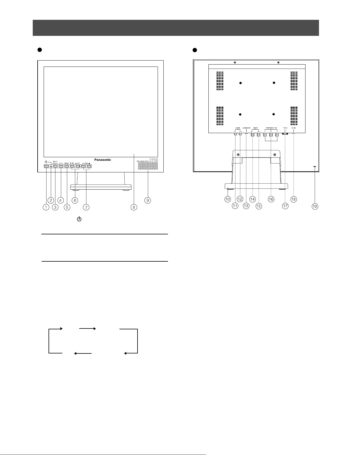
Front View
Rear View
a Power Button ( )
This button turns the power of the monitor on and off.
Note:
• Even if the POWER button is turned off and the
power indicator lits off, power supply in AC Adapter
does not turn off.
b Power Indicator
Lights up when the POWER button of the monitor is turned
on.
c Input Select Button (INPUT SELECT)
Pressing this button once, indicates the video input currently on
use.
Pressing repeatedly changes the video input in the sequence
shown below.
VIDEO
PC
S-VIDEO
COMPONENT
d Auto Button (AUTO)
This button is for auto tuning of picture size and position of PC
input.
e Menu Button (MENU)
Pressing this button displays or removes display of Video
Adjustment Menu.
f Direction Buttons ( PIP / POS)
These buttons move the cursor to the item parameters in the
Video Adjustment Menu.
PIP : Down
POS : Up
• PIP Button (Picture-In-Picture)
Pressing this button displays or removes display of sub-
screen.
When Video, S-Video, or Component input is currently on
main screen, PC input displays on subscreen.
When PC input is currently on main screen. Video, S-Video,
or Component input displays on subscreen.
• POS Button (Position)
Press this button to change the position of subscreen located
on four corners of the LCD screen in clockwise direction.
g Decrement/Increment Buttons (AUDIO - / +)
Press these buttons to increase or decrease the audio volume.
These buttons also select the item parameter or level in the
Video Adjustment Menu.
h Display Panel
i Speaker
j Monitor Stand
k Audio Input Connector (AUDIO IN)
This connector receives audio signal from an external device
using audio cable and output to monitor’s built-in speaker.
7
Page 8
l Audio Output Connector (AUDIO OUT)
The audio input signal connected to the audio input connector
is looped through this connector.
p Component Video Input Connectors (COMPONENT
IN Y, Cb, Cr)
These connectors are used to input Component Video signal
(Y, Cb, Cr).
m S-Video Input Connector (S-VIDEO IN)
This connector is used to input S-Video signal.
n Video Input Connector (VIDEO IN)
This connector is used to input Composite Video signal.
q PC Input Connector (PC IN)
This connector is used to input analog RGB signal from PC.
Supported Timing Data are shown below.
r DC Input Connector (DC IN)
o Video Output Connector (VIDEO OUT)
The video input signal connected to the video input con-
nector is looped through to this connector and terminated
automatically.
This connector is used to plug the AC Adapter (supplied as
a standard accessory).
s Security slot
This slot can be used to insert lock based on Industry Standard
Specification (3 ~ 3.26 mm × 7 ~ 7.26 mm × 2.5 ~ 4 mm) for
theft prevention.
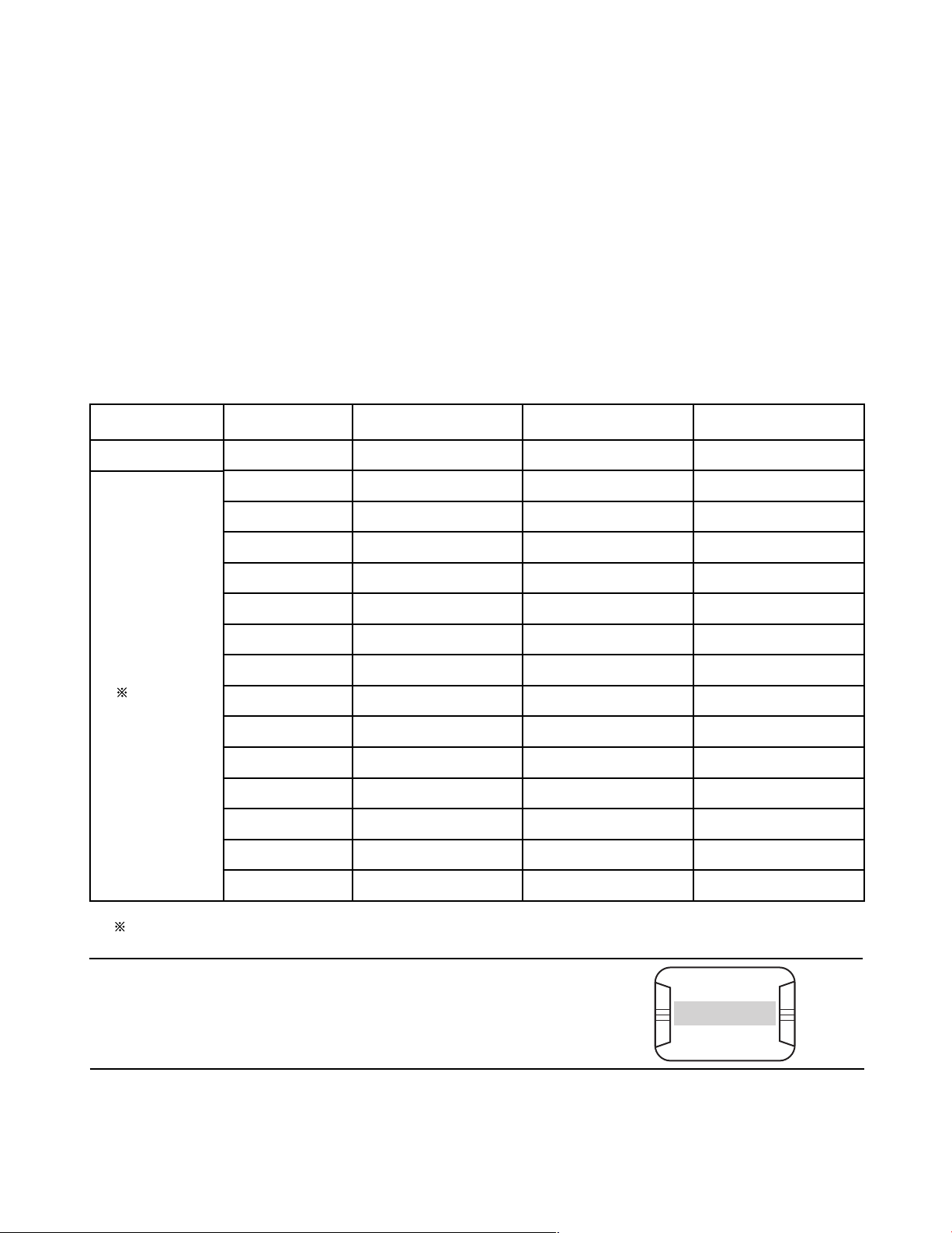
Timing Data Chart for PC input
This monitor supports the timing data listed below. It also supports in part other timing data not listed on the table.
Standard
Industry
VESA
Standard
Resolution
640 × 480
640 × 480
640 × 480
640 × 480
800 × 600
800 × 600
800 × 600
800 × 600
800 × 600
1024 × 768
1024 × 768
1024 × 768
1024 × 768
1280 × 1024
Dot Clock Frequency
(MHz)
25.17
31.50
31.50
36.00
36.00
40.00
50.00
49.50
56.25
65.00
75.00
78.75
94.50
108.00
Horizontal Frequency
(Hz)
31.46
37.86
37.50
43.26
35.16
37.88
48.08
46.88
53.67
48.36
56.48
60.02
68.68
63.98
Vertical Frequency
(Hz)
59.93
72.81
75.00
85.00
56.25
60.32
72.19
75.00
85.06
60.00
70.07
75.03
85.00
60.02
1280 × 1024
VESA: Video Electronics Standards Association
135.00
Notes:
• OUT OF RANGE is displayed on the center of the screen when the input resolution
specifications (Dot Clock Frequency, Horizontal Frequency, Vertical Frequency) are not
supported by this monitor.
• This is not a plug and play monitor.
8
79.98
75.02
OUT OF RANGE
Page 9
INSTALLATION
Cautions:
• The installation described below should be made by qualified service personnel or system installers.
• During installation, remove all connected cables and turn off the power of the monitor.
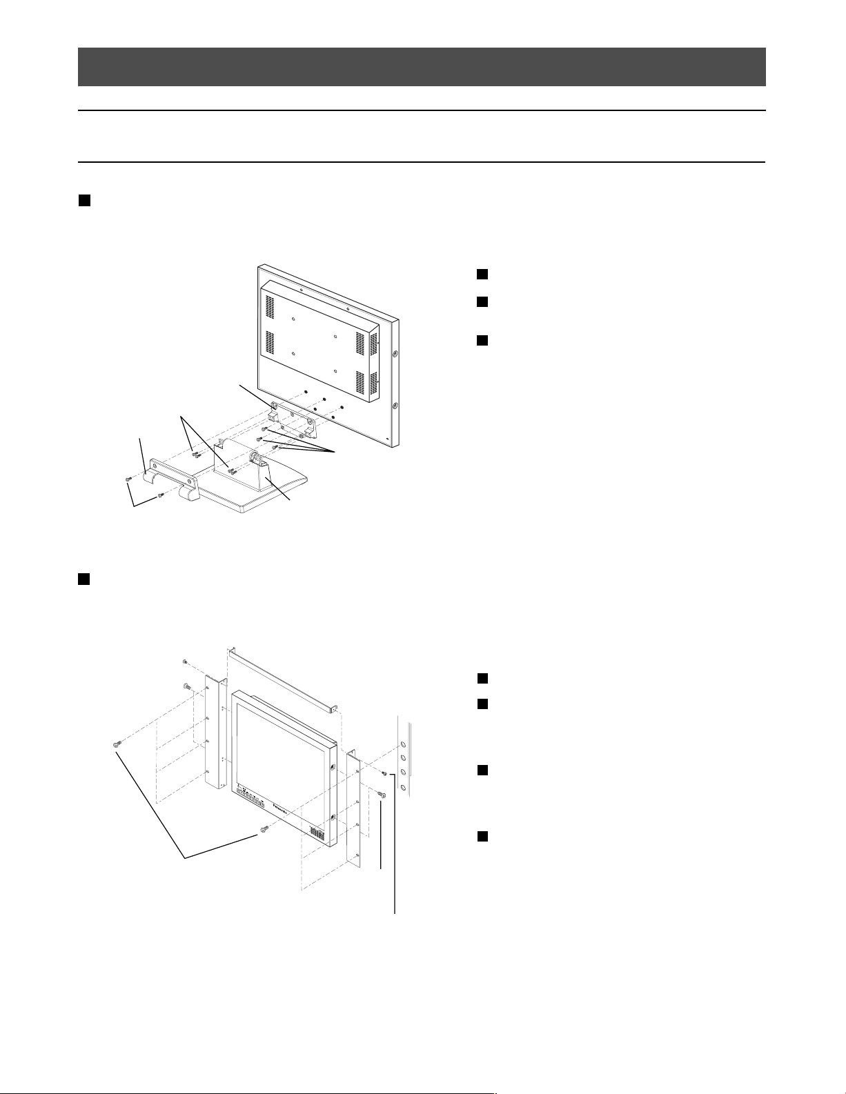
Removing Stand in the Monitor
Before installing this monitor on the wall or in the rack, the monitor stand shall be removed.
Remove two M4 screws to remove the stand cover.
1
Remove the stand assembly by removing four M4
2
screws from the stand.
Remove the stand arm by removing the three remaining
3
M4 screws.
Stand Arm
Mounting Screws
(M4)
Stand Cover
Mounting Screws
(M4)
Mounting Screws
(M4)
Stand
Mounting into the Rack
To install this monitor in rack, use the Rack Mount Bracket WQ-LM171 (optional) and rack mounting screws (procured locally).
Mounting Screws
(M3×8)
+
Upper Rack
Mount Bracket
EIA Rack
Mounting
Screws
(M4×12)
Mounting Screws
(M3×8)
Remove four screws on both side panels.
1
2
Mount the rack mount brackets to the sides of the moni-
tor.
Fix the rack mount brackets by using four supplied
screws (M4×12).
3
Mount the upper rack mount bracket on the upper side
of the monitor.
Fix the upper rack mount bracket by using two supplied
screws (M3×8).
4
Install securely the monitor in the rack using eight
screws (procured locally).
Mounting
Screws
(M4×12)
Rack Mounting Screws
(procured locally)
9
Page 10
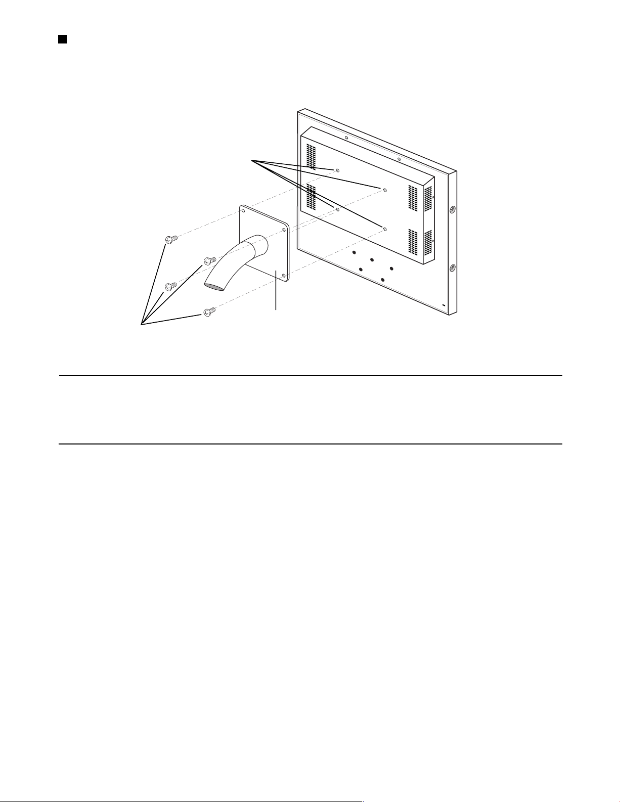
Mounting on the Wall
To install this monitor on the wall, use the VESA standard 100 mm pitch bracket (procured locally) and four screws (procured locally).
VESA mounting holes
(100 mm pitch)
VESA standard 100 mm pitch bracket
Wall Mounting Screws
(procured locally)
(procured locally)
Cautions:
• Do not block the ventilation opening or slots on the cover to prevent from overheating.
• When installing on places with vibration, fix securely the rear of the monitor by using reinforcement angle.
• To keep the temperature in the rack or wall where this monitor is installed within 40 °C {104 °F}, leave enough space (more than 1 U)
or install a cooling fan.
• AC Adapter should not be placed inside the rack or wall to prevent from heat up.
10
Page 11
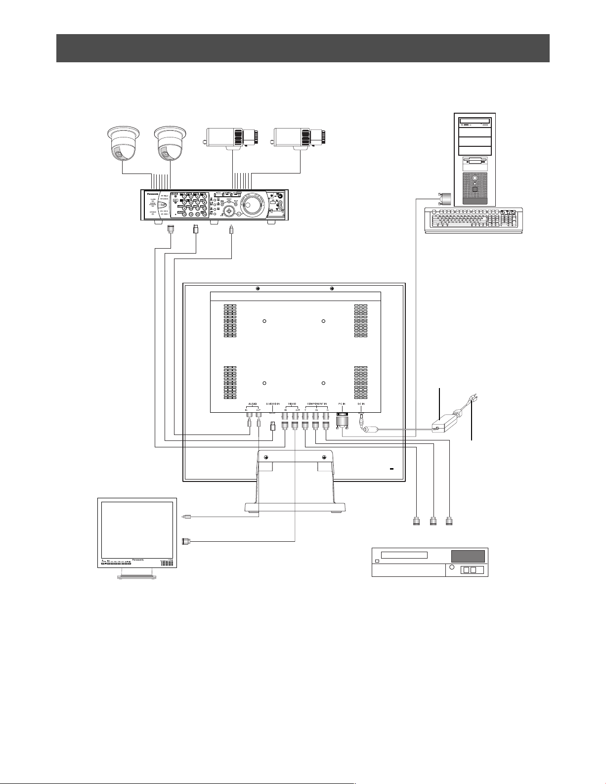
CONNECTIONS
PC
Digital Disk
Recorder
Video
Output
S-Video
Output
Video Output
Audio
Output
AC Adapter
(Supplied Accessory)
Power Cord
(Supplied Accessory)
Video Monitor
Audio
Input
Video
Input
Y Cb Cr
Component Output
DVD
11
Page 12

Connection with the Camera Site
Connect the video output of the camera site equipment to the VIDEO IN connector on the rear of the monitor using coaxial cable.
The maximum coaxial cable lengths available between the camera and monitor are shown below.
Cable Recommended Cable Length
RG-59/U 3C-2V
RG-6/U 5C-2V
RG-11/U 7C-2V
RG-15/U 10C-2V
250 m {825 feet}
500 m {1 650 feet}
600 m {1 980 feet}
800 m
{2 640 feet}
Multiple Monitor Connection
To monitor the same video/audio on multiple monitors, connect the VIDEO OUT/AUDIO OUT connector of this monitor to the VIDEO
IN/AUDIO IN of the other monitor using a coaxial cable and an audio cable.
Up to 10 monitors in total can be connected in series. If more than 10 monitors are connected there is a possibility of inferior picture quality.
Total cable length should not exceed 150 m {500 feet}.
Connection with the Digital Disk Recorder
• Recording on the Digital Disk Recorder
Connect the VIDEO OUT connector of this monitor to the video input of the Digital Disk Recorder or other video equipment using a coaxial
cable.
Connect the AUDIO OUT connector of this monitor to the audio input of the Digital Disk Recorder or other equipment using an audio cable,
if applicable.
• Monitoring the playback picture
Connect the VIDEO IN, S-VIDEO IN, COMPONENT IN connectors of this monitor to the video output of the Digital Disk Recorder or other
video equipment using coaxial cables.
• Monitoring the playback audio
Connect the AUDIO IN connector of this monitor to the audio output of the Digital Disk Recorder or other equipment using an audio
cable.
Using with Video Cassette Recorder
When a Video Cassette Recorder is used, the picture jitters when paused or fast forwarded. This is due to the property of a motion adaption
I/P conversion circuit, and at may become hard to see.
It is recommended to use a Digital Disk Recorder for this monitor.
Connection with PC
Connect the PC IN connector of this monitor to the video output (analog RGB) of the PC or other equipment using VGA cable.
Connection with DVD
Connect the COMPONENT IN connectors of this monitor to the component output connectors of DVD of other video equipment using
coaxial cables.
12
Page 13
STARTUP
Before operating this monitor, confirm that the camera, other video sources and peripherals are connected correctly and securely.
1. Turn on the monitor by pressing the
The power indicator lights up in green.
2. Select the desired input to be displayed by pressing the INPUT
POWER button.
SELECT button.
Onscreen display of the input signal currently on use displays
for approximately 2 seconds on upper left portion of the monitor screen.
Onscreen Display
VIDEO
S-VIDEO
COMPONENT
PC
Video Input
VIDEO IN
S-VIDEO IN
COMPONENT IN
PC IN
Onscreen display of NO SIGNAL displays on the center of the
screen as shown below, when there is no input signal.
NO SIGNAL
Note:
• During onscreen display of PROCESSING, all buttons
(except POWER button) are disabled. All buttons are
enabled after onscreen display of PROCESSING has
disappeared.
Onscreen display of
screen as shown below, when currently used input is disconnected.
VIDEO LOSS displays on the center of the
VIDEO LOSS
3. Press the INPUT SELECT button to select the desired input
signal while it is being displayed.
Pressing the button repeatedly displays input in the sequence
shown below. Onscreen display of selected input appears for
approximately 3 seconds.
VIDEO
PC COMPONENT
When input signal is being detected, onscreen display of
S-VIDEO
PROCESSING appears on upper left portion of screen and
performs normal video display.
When picture is set to PC input, pressing the
auto tuning of picture size and position.
Onscreen display of AUTO TUNING displays on the center of the
screen as shown below.
AUTO TUNING
AUTO button initiates
Note:
• Press the AUTO button, when screen resolution is
changed from the connected PC.
When changing the resolution setting, there are cases
that auto tuning will not be completed.
(Refer to page 19)
13
Page 14

AUDIO VOLUME CONTROL
The audio volume can be adjusted with the - or + button when
picture is displayed.
When these buttons are pressed, the icon and digital display of
audio volume setting appear on the upper left side of the screen.
- : Decreases the audio volume.
+ : Increases the audio volume.
14
Page 15

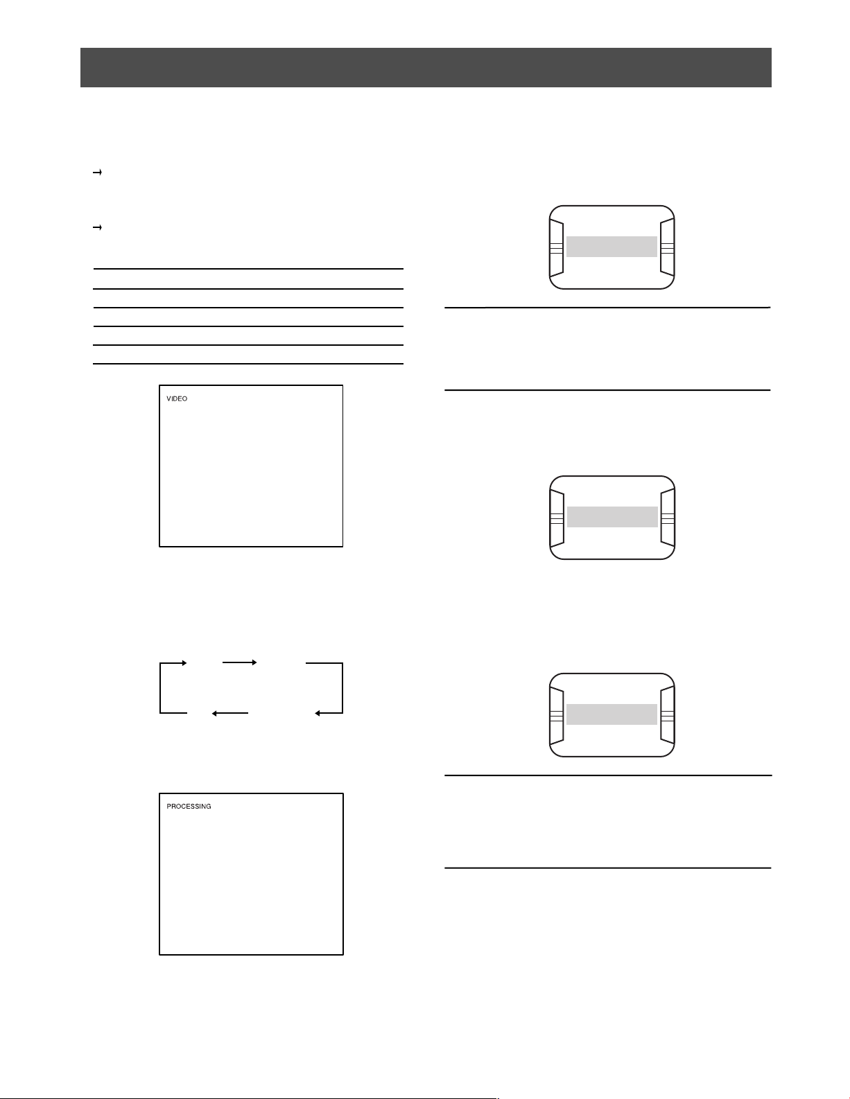
DISPLAYING VIDEO ADJUSTMENT MENU
Settings of this monitor can be done in the Video Adjustment Menu. The display on the screen differs depending on the input signal.
Caution:
• When onscreen display of NO SIGNAL, OUT OF RANGE, VIDEO LOSS, etc., appears on the center of the screen, the Video
Adjustment Menu cannot be displayed even if MENU button is pressed.
Displaying Video Adjustment Menu
1. Press the MENU button.
Video Adjustment Menu is displayed on the screen.
The menu title display changes depending on the input sig-
nal.
Input Signal Menu Title
Composite Video
S-Video
Component Video
PC
VIDEO IN
S-VIDEO IN
COMPONENT IN
PC IN
Menu Title
VIDEO IN
BRIGHT 0
CONTRAST 0
SHARPNESS 0
COLOR 0
TINT 0
VOLUME 0
H-POSITION 0
COLOR TEMP STANDARD
SCAN FULL
LANGUAGE ENGLISH
NORMAL SETTINGS
NTSC
Menu Title
VIDEO IN
BRIGHT 0
CONTRAST 0
SHARPNESS 0
COLOUR 0
TINT VOLUME 0
H-POSITION 0
COLOUR TEMP STANDARD
SCAN FULL
LANGUAGE ENGLISH
NORMAL SETTINGS
PA L
If the menu title is VIDEO IN, S-VIDEO IN or COMPONENT IN, the
following characters appears next to the menu title.
NTSC : When NTSC signal is inputted.
PA L : When PAL signal is inputted.
B/W : When black and white signal with 60 Hz/50 Hz field fre-
quency is inputted in composite video input.
During PC IN, the current signal being displayed is in the form
“Horizontal Resolution × Vertical Resolution @ Field Frequency”
on the latter part of the menu title based on the timing data list (on
page 8).
Note:
• In case the frequency of connected PC is not included in
the timing data list, the signal may not be displayed correctly.
2. Set each setting parameter.
Presently selected line is the line being highlighted.
Move to item down or up
: Press
PIP or POS button.
Change and adjust the settings
: Press - or + button.
Store the settings
: Settings are stored if menu button is pressed.
It displays off the Video Adjustment Menu.
Caution:
• If power is cut off while setting, it will not store the settings
that have changed.
15
Page 16

Setting of Composite Video / S-Video / Component Video Input
1. Display the Video Adjustment Menu.
(Refer to page 15)
VIDEO IN
BRIGHT 0
CONTRAST 0
SHARPNESS 0
COLOR 0
TINT 0
VOLUME 0
H-POSITION 0
COLOR TEMP STANDARD
SCAN FULL
LANGUAGE ENGLISH
NORMAL SETTINGS
VIDEO IN
BRIGHT 0
CONTRAST 0
SHARPNESS 0
COLOUR 0
TINT VOLUME 0
H-POSITION 0
COLOUR TEMP STANDARD
SCAN FULL
LANGUAGE ENGLISH
NORMAL SETTINGS
NTSC
PA L
2. Move the cursor to each setting parameter listed below with the
PIP or POS button, then adjust the level of the selected
item with the - or + button.
3. Move the cursor to the
COLOR TEMP (NTSC) or COLOUR
TEMP (PAL) parameters with the PIP or POS button, then
select color temperature of display with - or + button.
STANDARD : Pictures are displayed in normal
color temperature.
9300K : Pictures are displayed in bluish
color temperature.
6500K : Pictures are displayed in reddish
color temperature.
4. Move the cursor to the SCAN parameter with the PIP or
POS button, then select scanning area with - or + button.
FULL : Vertical and horizontal picture size are equal to
the display panel size. Picture aspect ratio is disregarded and the vertical size of picture is a little
stretched.
OVER : The vertical size of picture is fitted to the height of
the display panel.
Picture is cut on left and right sides for making the
expansion ratio of both vertical and horizontal size
into 1 : 1.
UNDER : The horizontal size of picture is fitted to the width
of the display panel.
Black horizontal bar appears on top and bottom of
the picture for making the expansion ratio of both
vertical and horizontal into 1 : 1.
5. Move the cursor to the
LANGUAGE parameter in the menu with
the PIP or POS button, then select the desired language
with the - or + button.
Pressing the button repeatedly displays the language as shown
below.
Item Effect Indicator
BRIGHT
CONTRAST
SHARPNESS
Darker Brighter
Less More
Soft Sharp
COLOR
(PAL: COLOUR)
Less More
TINT
(NTSC ONLY)
VOLUME
Reddish
Greenish
Decrease Inccrease
H-POSITION
Left Right
Notes:
• BRIGHT, CONTRAST, SHARPNESS, COLOR,
and TINT can be set to different values for each input
signal.
• TINT applies for NTSC system only.
16
Page 17

6. To reset the monitor to the default settings, move the cursor to
the NORMAL SETTINGS with the PIP or POS button,
then press the
- or + button to restore the default settings.
Onscreen display of NORMAL SETTINGS as shown below
appears on the center of the screen when - or + button is
pressed.
Note:
• During reset, setting parameters of Video Adjustment
Menu only are being reset.
NORMAL SETTINGS
VIDEO IN
BRIGHT -12
CONTRAST 8
SHARPNESS -16
COLOR -6
TINT -2
VOLUME -4
H-POSITION 3
COLOR TEMP 6500K
SCAN FULL
LANGUAGE ENGLISH
NORMAL SETTINGS
VIDEO IN
BRIGHT 0
CONTRAST 0
SHARPNESS 0
COLOR 0
TINT 0
VOLUME 0
H-POSITION 0
COLOR TEMP STANDARD
SCAN FULL
LANGUAGE ENGLISH
NORMAL SETTINGS
7. After setting the parameters, press the
NTSC
NTSC
MENU button.
Set values will be stored and the Video Adjustment Menu will
exit.
Caution:
• If power is cut off while setting, it will not store the set-
tings that have changed.
17
Page 18

Setting of PC Input
1. Display the Video Adjustment Menu.
(Refer to page 15)
PC IN
BRIGHT 0
CONTRAST 0
H-POSITION 0
V - POSITION 0
CLOCK 0
PHASE 0
COLOR TEMP USER COLOR
USER COLOR R 20
USER COLOR G 20
USER COLOR B 20
OSD H-POSITION 0
OSD V-POSITION 0
VOLUME 0
LANGUAGE ENGLISH
NORMAL SETTINGS
1280x1024@60Hz
2. Set the BRIGHT, CONTRAST, VOLUME, and LANGUAGE
parameters. Please refer to page 16 for the operation method.
3. Move the cursor to each setting parameter listed below with the
PIP or POS button, then adjust the level of the selected
item with the - or + button.
Item Effect Indicator
H-POSITION
Right Left
V-POSITION
Down Up
CLOCK
Contract
Expand
PHASE
Right Left
OSD
H-POSITION
Left
Right
OSD
V-POSITION
Up
Down
Note:
• Each setting parameter can be set at a range of -20 ~
20. However, there are cases that no changes in set
value even when - or + button is pressed.
4. Move the cursor to the
COLOR TEMP parameter with the
PIP or POS button, then select color temperature of dis-
play with - or + button.
Set the RGB in step 5 in case USER COLOR is selected.
USER COLOR : Pictures are displayed in specified
color temperature.
9300K : Pictures are displayed in bluish
color temperature.
6500K : Pictures are displayed in reddish
color temperature.
5. Move the cursor to either USER COLOR R, USER COLOR G,
or USER COLOR B parameter in the menu with the PIP or
POS button, then adjust the red, green, or blue color for color
temperature.
- : Decreases the red, green, or blue color.
+ : Increases the red, green, or blue color.
6. To reset the monitor to the default settings, move the cursor to
NORMAL SETTINGS with the PIP or POS button,
the
then press the - or + button to restore the default settings.
When - or + button is pressed, NORMAL SETTINGS is dis-
played and then, AUTO TUNING is displayed on the center of
the screen as shown below.
Note:
• During reset, setting parameters of the Video Adjustment
Menu only are being reset.
NORMAL SETTINGS
PC IN
BRIGHT -12
CONTRAST 8
H-POSITION 5
V - POSITION 5
CLOCK 4
PHASE 7
COLOR TEMP 6500K
USER COLOR R 15
USER COLOR G 15
USER COLOR B 15
OSD H-POSITION 1
OSD V-POSITION 20
VOLUME 2
LANGUAGE ENGLISH
NORMAL SETTINGS
PC IN
BRIGHT 0
CONTRAST 0
H-POSITION 5
V - POSITION 5
CLOCK 4
PHASE 7
COLOR TEMP USER COLOR
USER COLOR R 20
USER COLOR G 20
USER COLOR B 20
OSD H-POSITION 1
OSD V-POSITION 20
VOLUME 2
LANGUAGE ENGLISH
NORMAL SETTINGS
1280x1024@60Hz
1280x1024@60Hz
AUTO TUNING
18
Page 19

Notes:
• H-POSITION, V-POSITION, CLOCK and PHASE will
change depending on the input signal.
Normally, these parameters need not to be set.
In case the position of the picture is still shifted even
AUTO TUNING button is pressed, operate base on the
procedure below.
1. Set the left edge of the picture to the left edge of the
monitor screen while adjusting
2. Set the right edge of the picture to the right edge of the
monitor screen while adjusting CLOCK.
3. Repeat steps 2 and 3 until the position of the picture is
on the center of the screen.
OSD H-POSITION and OSD V-POSITION settings can-
•
not be reset.
• Adjustment parameters from PC are not supported.
H-POSITION.
Picture-in-Picture Mode Monitoring
CONNECTING WITH WJ-HD300 SERIES
• There is a possibility that the picture will be shifted if the
Monitor (VGA) terminal of the Digital Disk Recorder WJHD300 series is connected to the PC input even AUTO
button is pressed. In this case, adjust
and CLOCK following the procedure indicated in upper
left note.
7. After setting the parameters, press the
Set values will be stored and the Video Adjustment Menu will
exit.
H-POSITION
MENU button.
Caution:
• If power is cut off setting, it will not store the settings
that have changed.
1. Press the PIP button to display the subscreen in approxi-
mately 2 seconds waiting time, as shown below.
• PC Input is displayed in subscreen when Composite Video,
S-Video or Component Video inputs is displayed on main
screen of the monitor.
• VIDEO, S-VIDEO or COMPONENT is displayed in subscreen
depending on the last input done prior to switching to PC Input
when PC input is displayed on main screen of the monitor.
VIDEO
The input signal of subscreen displays on the upper right of
display panel.
2. After displaying the subscreen, pressing the
move the subscreen as shown below.
3
2
3. Press the
or Component input that appears on the subscreen when PC
input is currently on the main screen.
INPUT SELECT button in selecting Video, S-Video,
POS button will
4
1
19
Page 20

TROUBLESHOOTING
Phenomenon
Power is not turned on.
NO SIGNAL is displayed on the center
of the screen and picture is not displayed.
Color is abnormal (red and blue is reverse,
sync is not in order) during Component
Input.
Menu is not displayed even if
button is pressed.
Volume cannot adjust even if the
button is pressed.
MENU
- or +
Cause
DC input terminal of the AC Adapter is
not properly connected.
Power supply plug is not properly connected.
The AC cord is not properly connected to
the AC Adapter.
Cable is not properly connected.
Cable is not connected to respective
signal input.
Connection of the input signals are not in
proper order (Y, Cb, Cr).
Menu is not displayed when there is no
input signal.
Volume cannot be adjusted when picture
is not displayed.
What to do
Connect the DC input terminal of the
AC Adapter to DC IN connector of this
monitor.
Connect the power supply plug to the
AC outlet.
Connect the AC cord to the AC Adapter.
Connect the respective cable properly.
Connect the cable properly to its respective input.
Rearrange to connect the cables in proper order.
Press the
change the input signal.
Press the
change to channel with input.
INPUT SELECT button to
INPUT SELECT button to
Input signal cannot change even if the
INPUT SELECT button is pressed.
Position of picture display during PC
input is shifted.
The power cord insulation is damaged.
The power cord and the power plug of
the AC Adapter are hot during use.
The power cord gets warm or hot if bent
or pulled during use.
The INPUT SELECT button is pressed
while onscreen display of PROCESSING
displays on the screen.
The timing data of connected PC is not
supported.
The power cord or the plug is damaged.
If you continue to use it, a fire or electric
shock may occur.
Press the
onscreen display of PROCESSING disappeared.
Press the
tuning.
In cases when it is still shifted, read
page 19 and follow the procedure for
auto tuning.
Unplug the AC Adapter immediately,
and refer servicing to qualified service
personnel.
INPUT SELECT button after
AUTO button for automatic
20
Page 21

SPECIFICATIONS
Video Monitor
Power Source: 12 V DC, 3 A (Use the supplied AC Adapter)
Power Consumption: 43 W (with AC Adapter)
Display Panel: 17.0" TFT LCD, Built in 2 dual CCFTs
Display Area: 338 mm (H) × 270 mm (V)
Number of Pixels: 1280 × 1024 (SXGA)
Aspect Ratio: 5 : 4
Brightness: 250 cd/m2 [Typical]
Contrast Ratio: 1000 : 1 [Typical]
Display Colors: Approx. 16,770,000
Viewing Angle (L-R / U-D): 178°/ 178° (Contrast 10 : 1) [Typical]
TV Mode: Composite Video In: NTSC / PAL (Auto)
Component Video In / S-Video In: 525i / 625i (Auto)
Horizontal Resolution: 500 TV lines
Video In: 1.0 V [P-P] composite / 75Ω, BNC connector
Video Out: Looped through output with auto termination, BNC connector
S-Video In: Y: 1.0 V [P-P] / 75Ω, C: 0.3 V [P-P] / 75Ω, Mini DIN jack
Component In: Y: 1.0 V [P-P] / 75Ω, BNC connector
Cb / Cr: 0.7 V [P-P] / 75Ω, BNC connector × 2
PC In: R / G / B: 0.7 V [P-P] / 75Ω, H / V sync: TTL, 15-pin Mini D-sub
Speaker Out: 0.5 W
Audio In: -8 dB / Hi-Z, RCA pin jack
Audio Out: Looped through output, RCA pin jack
Color Temperature: Video In: Standard / 9300K / 6500K
PC In: User color / 9300K / 6500K
Sub-picture Size: 1 / 9 of full size picture
Ambient Operation Temperature: 0 °C to +40 °C {32 °F to +104 °F}
Ambient Operation Humidity: Less than 90 %
Wall Mounting Hole: 100 mm (VESA standard)
Dimension:
With a stand: 380 mm (W) × 394 mm (H) × 193 mm (D)
{14-24/25" (W) × 15-1/2" (H) × 7-3/5" (D)}
Without a stand: 380 mm (W) × 338 mm (H) × 70 mm (D)
{14-24/25" (W) × 13-3/10" (H) × 2-3/4" (D)}
Weight:
With a stand: 6.5 k {14.4 lbs}
Without a stand: 5.2 k {11.5 lbs}
g
g
Outer Appearance:
Monitor: Solid black metallic
Stand: Solid black
21
Page 22

SPECIFICATIONS
AC Adapter
Power Supply: 100 V AC ~ 240 V AC, 50 / 60 Hz
Output Voltage: 12 V DC
Output Current: 4 A
Dimension: 120 mm (L) × 60 mm (W) × 35 mm (H) (without DC cable)
{4-18/25" (L) × 2-9/25" (W) × 1-9/25" (H)}
Weight: 0.35 k {0.77 lbs}
g
STANDARD ACCESSORIES
Operating Instructions (this book) ............................................................................................ 1 pc.
Warranty Certificate .................................................................................................................. 1 pc.
The following items are for installation:
AC Adapter ............................................................................................................................... 1 pc.
Power Cord ............................................................................................................................... 1 pc.
22
Page 23

VERSION FRANÇAISE
Attention :
Préalablement à la connexion ou à l’emploi du produit, lire
l’étiquette au dos.
CAUTION
RISK OF ELECTRIC SHOCK
DO NOT OPEN
ATTENTION : AFIN DE PRÉVENIR LE RISQUE DE
CHOCS ÉLECTRIQUES, NE PAS RETIRER LES
VIS. TOUTE RÉPARATION DEVRAIT ÊTRE
CONFIÉE À UN PERSONNEL QUALIFIÉ.
Le symbole de l’éclair dans un triangle
équilatéral indique la présence d’une tension
suffisamment élevée pour engendrer un
risque de chocs électriques.
SA 1965
Le point d’exclamation dans un triangle équilatéral indique que le manuel d’instructions
inclus avec l’appareil contient d’importantes
recommandations quant au fonctionnement
et à l’entretien de ce dernier.
FRANÇAIS
For Canada
This Class A digital apparatus complies with Canadian
ICES-003.
Cet appareil numérique de la classe A est conforme
à la norme NMB-003 du Canada.
SA 1966
Coupure de l’alimentation. Les appareils
équipés ou non équipés d’interrupteurs
d’alimentation à positions marche-arrêt (ONOFF) sont alimentés dès que le cordon d’alimentation secteur est raccordé à la source
d’alimentation; cependant, il faut savoir que
l’appareil n’est alimenté que dans la mesure
où l’interrupteur d’alimentation à positions
marche-arrêt se trouve en position marche
(ON). Débranchez le cordon d’alimentation
pour couper l’alimentation générale de tous
les appareils.
MISE EN GARDE : • Cet appareil doit être mis à la terre.
• Afin de prévenir tout risque d’incendie ou de chocs électriques, éviter d’exposer cet appareil à la pluie ou
à une humidité excessive. L’appareil ne doit pas être exposé aux gouttes ou aux éclaboussures et aucun
objet contenant un liquide, comme par exemple un vase, ne doit être placé sur l’appareil.
Nous vous suggérons de noter, dans l’espace prévu cidessous, le numéro de série inscrit à l’arrière de l’appareil,
et de conserver ce manuel comme mémorandum de votre
achat afin d’en permettre l’identification en cas de vol.
Numéro de modèle WV-LC1710
Numéro de série
23
Page 24

INSTRUCTIONS DE SÉCURITÉ IMPORTANTES
1) Lire les présentes instructions.
2) Conserver ces instructions.
3) Tenir compte de tous les avertissements.
4) Se conformer à toutes les instructions.
5) Ne pas utiliser cet appareil près de lieux en présence d’eau.
6) Nettoyer uniquement avec un chiffon sec.
7) N’obturer aucune des ouvertures d’aération. Installer conformément aux instructions du fabricant.
8) Ne pas installer à proximité de sources de chaleur telles que des radiateurs, des bouches de chauffage, des appareils de chauffage ou
tout autre appareil (y compris les amplificateurs) produisant de la chaleur.
9) Ne pas aller à l’encontre de l’objectif de sécurité de la prise polarisée ou de la prise de mise à la terre. Une prise polarisée possède deux
lames, dont l’une est plus large que l’autre. Une prise de mise à la terre possède deux lames ainsi qu’un troisième élément, un ergot
de mise à la terre. La lame qui est large ou le troisième élément, l’ergot, sont installés pour assurer votre sécurité. Si la prise fournie ne
s’engage pas correctement dans votre prise, prière de consulter un électricien pour qu’il effectue le remplacement de l’ancienne prise de
sortie secteur.
10) Voir à ce qu’on ne marche pas sur le cordon d’alimentation ou qu’on ne l’écrase pas, particulièrement à l’emplacement des fiches, des
prises de courant et de sa sortie de l’appareil.
11) Utiliser uniquement les fixations ou les accessoires spécifiés par le fabricant.
12) Utiliser uniquement le chariot, le support, le trépied, la console ou la table spécifié par le fabricant ou vendu avec l’appareil. Lorsqu’un
chariot est employé, déplacer l’appareil sur chariot avec prudence pour éviter qu’il ne tombe et ne blesse quelqu’un.
S3125A
13) Débrancher cet appareil pendant les orages électriques ou s’il n’est pas utilisé sur de longues périodes de temps.
14) Toute réparation ou dépannage doit être confié à un personnel qualifié. Un dépannage est nécessaire lorsque l’appareil a été endommagé
d’une manière quelconque, par exemple, lorsque le cordon d’alimentation électrique ou la prise sont endommagés, si un liquide s’est
répandu dessus ou si des objets sont tombés dans l’appareil, lorsque l’appareil a été exposé à la pluie ou à l’humidité, ne fonctionne pas
normalement ou s’il a fait une chute.
24
Page 25

LIMITATION DE RESPONSABILITÉ
CETTE PUBLICATION EST FOURNIE “TELLE QUELLE” SANS
GARANTIE D’AUCUNE SORTE, EXPRESSE OU IMPLICITE,
Y COMPRIS NOTAMMENT LES GARANTIES IMPLICITES
DE VALEUR MARCHANDE, D’ADAPTATION À TOUT BUT
PARTICULIER OU DE NON-INFRACTION DES DROITS D’UN
TIERS.
DÉNI DE GARANTIE
SAUF EN CE QUI TOUCHE AU REMPLACEMENT OU À
L’ENTRETIEN RAISONNABLE DU PRODUIT, MATSUSHITA
ELECTRIC INDUSTRIAL CO. LTD. NE SERA EN AUCUN CAS
TENUE POUR RESPONSABLE ENVERS UNE PARTIE OU
UNE PERSONNE QUELCONQUE, NOTAMMENT DANS LES
CAS MENTIONNÉS CI-DESSOUS :
1) TOUS DOMMAGES ET PERTES, QU’ILS SOIENT ENTRE
AUTRES DIRECTS OU INDIRECTS, SPÉCIAUX, CONSÉCUTIFS OU EXEMPLAIRES, RELATIFS AU PRODUIT OU
ISSUS DE CELUI-CI;
CETTE PUBLICATION POURRAIT CONTENIR DES INEXACTITUDES TECHNIQUES OU DES ERREURS TYPOGRAPHIQUES. DES CHANGEMENTS SONT APPORTÉS AUX
INFORMATIONS CI-INCLUSES, À TOUT MOMENT, AFIN
D’AMÉLIORER CETTE PUBLICATION, LE(S) PRODUIT(S)
CORRESPONDANT(S) OU LES DEUX.
2) UNE BLESSURE CORPORELLE OU TOUT DÉGÂT CAUSÉ
PAR UN USAGE INAPPROPRIÉ OU UNE UTILISATION
NÉGLIGENTE DE L’UTILISATEUR;
3) LE DÉMONTAGE, LA RÉPARATION OU LA MODIFICATION NON AUTORISÉS DU PRODUIT EFFECTUÉS PAR
L’UTILISATEUR;
4) TOUT PROBLÈME, INCOMMODITÉ IMPORTANTE OU
PERTE OU ENDOMMAGEMENT DÉCOULANT DE LA
COMBINAISON DU SYSTÈME AVEC DES APPAREILS DE
TIERS.
25
Page 26

TABLE DES MATIÈRES
INSTRUCTIONS DE SÉCURITÉ IMPORTANTES. . . . . . . . . . . . . . . . . . . . . . . . . . . . . . . . . . . . . . . . . . . . . . . . . . . 24
LIMITATION DE RESPONSABILITÉ . . . . . . . . . . . . . . . . . . . . . . . . . . . . . . . . . . . . . . . . . . . . . . . . . . . . . . . . . . . . . 25
DÉNI DE GARANTIE . . . . . . . . . . . . . . . . . . . . . . . . . . . . . . . . . . . . . . . . . . . . . . . . . . . . . . . . . . . . . . . . . . . . . . . . . 25
PRÉFACE. . . . . . . . . . . . . . . . . . . . . . . . . . . . . . . . . . . . . . . . . . . . . . . . . . . . . . . . . . . . . . . . . . . . . . . . . . . . . . . . . . 27
FONCTIONS . . . . . . . . . . . . . . . . . . . . . . . . . . . . . . . . . . . . . . . . . . . . . . . . . . . . . . . . . . . . . . . . . . . . . . . . . . . . . . . 27
PRÉCAUTIONS . . . . . . . . . . . . . . . . . . . . . . . . . . . . . . . . . . . . . . . . . . . . . . . . . . . . . . . . . . . . . . . . . . . . . . . . . . . . . 27
PRINCIPALES COMMANDES ET FONCTIONS . . . . . . . . . . . . . . . . . . . . . . . . . . . . . . . . . . . . . . . . . . . . . . . . . . . . 28
Vue de face . . . . . . . . . . . . . . . . . . . . . . . . . . . . . . . . . . . . . . . . . . . . . . . . . . . . . . . . . . . . . . . . . . . . . . . . . . . . 28
Vue de dos . . . . . . . . . . . . . . . . . . . . . . . . . . . . . . . . . . . . . . . . . . . . . . . . . . . . . . . . . . . . . . . . . . . . . . . . . . . . . 28
INSTALLATION. . . . . . . . . . . . . . . . . . . . . . . . . . . . . . . . . . . . . . . . . . . . . . . . . . . . . . . . . . . . . . . . . . . . . . . . . . . . . . 30
Démontage du support du moniteur . . . . . . . . . . . . . . . . . . . . . . . . . . . . . . . . . . . . . . . . . . . . . . . . . . . . . . . . . 30
Montage sur bâti . . . . . . . . . . . . . . . . . . . . . . . . . . . . . . . . . . . . . . . . . . . . . . . . . . . . . . . . . . . . . . . . . . . . . . . . 30
Montage au mur . . . . . . . . . . . . . . . . . . . . . . . . . . . . . . . . . . . . . . . . . . . . . . . . . . . . . . . . . . . . . . . . . . . . . . . . 31
RACCORDS. . . . . . . . . . . . . . . . . . . . . . . . . . . . . . . . . . . . . . . . . . . . . . . . . . . . . . . . . . . . . . . . . . . . . . . . . . . . . . . . 32
Raccord à un site de caméras. . . . . . . . . . . . . . . . . . . . . . . . . . . . . . . . . . . . . . . . . . . . . . . . . . . . . . . . . . . . . . 33
Raccord à plusieurs moniteurs . . . . . . . . . . . . . . . . . . . . . . . . . . . . . . . . . . . . . . . . . . . . . . . . . . . . . . . . . . . . . 33
Raccord à un enregistreur de disques numériques . . . . . . . . . . . . . . . . . . . . . . . . . . . . . . . . . . . . . . . . . . . . . 33
Raccord à un PC . . . . . . . . . . . . . . . . . . . . . . . . . . . . . . . . . . . . . . . . . . . . . . . . . . . . . . . . . . . . . . . . . . . . . . . . 33
Raccord à un DVD. . . . . . . . . . . . . . . . . . . . . . . . . . . . . . . . . . . . . . . . . . . . . . . . . . . . . . . . . . . . . . . . . . . . . . . 33
DÉMARRAGE . . . . . . . . . . . . . . . . . . . . . . . . . . . . . . . . . . . . . . . . . . . . . . . . . . . . . . . . . . . . . . . . . . . . . . . . . . . . . . 34
COMMANDE DE VOLUME AUDIO . . . . . . . . . . . . . . . . . . . . . . . . . . . . . . . . . . . . . . . . . . . . . . . . . . . . . . . . . . . . . . 35
AFFICHAGE DU MENU DE RÉGLAGE VIDÉO . . . . . . . . . . . . . . . . . . . . . . . . . . . . . . . . . . . . . . . . . . . . . . . . . . . . 36
Affichage du menu de réglage vidéo. . . . . . . . . . . . . . . . . . . . . . . . . . . . . . . . . . . . . . . . . . . . . . . . . . . . . . . . . 36
Configuration de l’entrée vidéo composite / S-vidéo / vidéo en composantes . . . . . . . . . . . . . . . . . . . . . . . . . 37
Configuration de l’entrée PC . . . . . . . . . . . . . . . . . . . . . . . . . . . . . . . . . . . . . . . . . . . . . . . . . . . . . . . . . . . . . . 39
Visionnement en mode Image dans l’image . . . . . . . . . . . . . . . . . . . . . . . . . . . . . . . . . . . . . . . . . . . . . . . . . . 40
RÉSOLUTION DES PROBLÈMES . . . . . . . . . . . . . . . . . . . . . . . . . . . . . . . . . . . . . . . . . . . . . . . . . . . . . . . . . . . . . . 41
CARACTÉRISTIQUES TECHNIQUES. . . . . . . . . . . . . . . . . . . . . . . . . . . . . . . . . . . . . . . . . . . . . . . . . . . . . . . . . . . . 42
Moniteur vidéo . . . . . . . . . . . . . . . . . . . . . . . . . . . . . . . . . . . . . . . . . . . . . . . . . . . . . . . . . . . . . . . . . . . . . . . . . . 42
Adaptateur CA . . . . . . . . . . . . . . . . . . . . . . . . . . . . . . . . . . . . . . . . . . . . . . . . . . . . . . . . . . . . . . . . . . . . . . . . . 43
ACCESSOIRES STANDARD . . . . . . . . . . . . . . . . . . . . . . . . . . . . . . . . . . . . . . . . . . . . . . . . . . . . . . . . . . . . . . . . . . 43
26
Page 27

PRÉFACE
Ce moniteur est un ACL de 17", doté d’un circuit de conversion IP
d’adaptation de mouvement et d’un circuit de séparation Y/C pour
l’affichage d’images à haute définition et à haute résolution.
FONCTIONS
• Panneau haute résolution (SXGA) à haut contraste intégré, angle
large et gamme de couleurs vraies sur 8 bits.
• Entrées sélectionnables, à choisir entre une entrée vidéo
composite, une entrée S-vidéo, une entrée vidéo en composantes
et une entrée analogique de signal RGB pour ordinateurs (PC).
• Commutation automatique entre les systèmes d’affichage en
NTSC et PAL.
• Possibilités d’affichage sur PC pouvant prendre en charge les
résolutions VGA (640 × 480) ~ SXGA (1280 × 1024). Possibilité
de régler automatiquement la taille et la position de l’image.
• Une entrée et une sortie audio externe avec capacité de sortie
sur enceinte incorporée de 0,5 W.
• Menu de réglage à l’écran.
PRÉCAUTIONS
• Déléguer l’ensemble des travaux d’installation de ce
produit à du personnel qualifié.
• Ne jamais obstruer les orifices d’aération du couvercle.
Afin d’éviter toute surchauffe de l’appareil, le placer à environ
5 cm, au moins, du mur.
• Faire attention à ce que des objets métalliques ne
passent pas à travers les orifices.
Ceci risquerait en effet d’endommager l’appareil de façon
permanente. Dans un tel cas, éteindre immédiatement l’appareil,
puis contacter un personnel de dépannage qualifié.
• Ne jamais essayer de démonter l’appareil vous-même.
Afin d’éviter tout choc électrique, ne dévisser aucune vis ou cou-
vercle. Il n’y aucune pièce réparable par l’utilisateur à l’intérieur.
Toujours contacter du personnel qualifié pour toute opération
d’entretien nécessaire.
• Manipuler l’appareil avec douceur.
Ne jamais le secouer ou taper dessus, car ceci pourait
l’endommager.
• Ne jamais exposer l’appareil à la pluie ou à l’humidité, et
ne jamais l’allumer dans des endroits humides.
Agir immédiatement si l’appareil se mouille. Couper l’alimentation,
puis confier l’entretien de l’appareil à du personnel qualifié.
L’humidité risque en effet d’endommager l’appareil et pourrait
causer des décharges électriques.
• Ne jamais utiliser l’appareil en dehors des plages de
température, d’humidité ou d’alimentation recommandées.
Cet appareil peut être utilisé dans une plage de températures
• Alimentation électrique auto-régulée avec en entrée 100 V CA ~
240 V CA (adaptateur CA)
Remarque : Le cordon d’alimentation CA fourni n’est destiné
qu’à l’alimentation de 120 V CA. Il faut changer de cordon
d’alimentation CA si le courant est différent.
• Boîtier tout en métal. Possibilité de montage dans un bâti standard
EIA à l’aide d’un support de montage sur bâti en option.
• Les orifices de montage au mur situés à l’arrière du moniteur sont
compatibles avec la norme VESA. Le moniteur peut également être
installé au mur en utilisant un support de montage disponible
dans le commerce.
VESA : Video Electronics Standards Association (Association de
normalisation de la vidéo électronique)
allant de 0 °C ~ +40 °C et avec une humidité inférieure à 90 %.
La gamme des tensions applicables à cette unité va de 100 V CA
à 240 V CA, 50/60 Hz avec un adaptateur CA.
Ne jamais utiliser des détergents forts ou abrasifs pour
•
nettoyer le boîtier de l’appareil.
Quand l’appareil est sale, le nettoyer avec un linge sec. Si la
saleté est tenace, utiliser un détergent doux en frottant lentement.
Essuyer ensuite les résidus de détergent avec un linge sec.
• Le panneau d’affichage est recouvert d’un revêtement
spécial.
Ne jamais appuyer dessus avec des objets pointus ou l’essuyer
avec des produits abrasifs. Ceci risquerait de causer des éraflures
ou d’endommager le panneau d’affichage.
• Le panneau d’affichage a été réalisé à l’aide d’une
technologie de pointe.
Il se peut néanmoins que des points trop lumineux ou trop
sombres apparaissent à l’écran. On considère en général que
l’appareil fonctionne normalement s’il y a 99,99 % de pixels
actifs.
• N’utiliser que l’adaptateur CA fourni.
Il n’est pas possible d’utiliser d’autres adaptateurs CA.
•
Avant de couper l’alimentation électrique fournie par
l’adaptateur CA, débrancher le cordon ou couper le
courant à partir du coupe-circuit de la prise dont dépend
cet appareil.
Lors de la réinstallation de l’appareil, choisir un endroit où la prise
et le coupe-circuit seront faciles à atteindre.
27
Page 28

PRINCIPALES COMMANDES ET FONCTIONS
Vue de face
Vue de dos
a Touche de mise en marche ( )
Cette touche permet d’allumer et d’éteindre le moniteur.
Remarque :
• Prendre en compte le fait que même lorsque la
touche POWER (touche de mise en marche) est en
position désactivée et que le témoin est éteint, l’adaptateur CA reste sous tension.
b Témoin de mise en marche
Ce témoin s’allume lorsque la touche POWER est enfoncée.
c Touche de sélection d’entrée (INPUT SELECT)
Sur une pression unique de cette touche, l’entrée vidéo active
s’affiche.
Le fait de rappuyer sur cette touche fait défiler les différentes
entrées vidéo dans l’ordre indiqué ci-dessous.
VIDEO
PC
S-VIDEO
COMPONENT
d Touche auto (AUTO)
Cette touche sert à la syntonisation automatique de la taille de
l’image et de la position en entrée PC.
e Touche de menu (MENU)
Le fait d’appuyer sur cette touche permet d’afficher ou d’effacer
l’affichage du menu de réglage vidéo.
f Touches de direction ( PIP / POS)
Ces touches permettent de déplacer le curseur entre les diffé-
rents éléments du menu de réglage vidéo.
PIP : Bas
POS : Haut
• Touc he PIP (Picture-In-Picture : Image dans l’image)
Le fait d’appuyer sur cette touche permet d’afficher ou d’effa-
cer l’image incrustée.
Lorsque l’entrée vidéo, S-vidéo ou en composantes est
affichée à l’écran, l’entrée PC s’affiche comme image incrustée.
Lorsque l’entrée PC est affichée à l’écran, l’entrée vidéo, S-
vidéo ou en composantes s’affiche comme image incrustée.
• Touc he POS (Position)
Appuyer sur cette touche pour changer, dans le sens des
aiguilles d’une montre, la position de l’image incrustée dans
un des quatre coins de l’écran ACL.
g Touches de diminution/augmentation (AUDIO - / +)
Appuyer sur ces touches pour augmenter ou réduire le volume
sonore.
Ces touches permettent également de sélectionner certains
paramètres ou niveaux dans le menu de réglage vidéo.
h Panneau d’affichage
i Enceinte
j Support du moniteur
k Connecteur d’entrée audio (AUDIO IN)
Ce connecteur permet de connecter un signal audio en prove-
nance d’un appareil externe à la sortie des enceintes intégrées
du moniteur.
28
Page 29

l Connecteur de sortie audio (AUDIO OUT)
Le signal audio qui arrive au niveau du connecteur d’entrée
audio passe à travers ce connecteur.
m Connecteur d’entrée S-vidéo (S-VIDEO IN)
Ce connecteur s’utilise pour les signaux S-vidéo.
n Connecteur d’entrée vidéo (VIDEO IN)
Ce connecteur s’utilise pour les signaux vidéo composites.
o Connecteur de sortie vidéo (VIDEO OUT)
Le signal vidéo qui arrive au niveau du connecteur d’en-
trée vidéo passe à travers ce connecteur où il est terminé
automatiquement.
p Connecteurs d’entrée vidéo en composantes
(COMPONENT IN Y, Cb, Cr)
Ces connecteurs s’utilisent pour les signaux vidéo en compo-
santes (Y, Cb, Cr).
q Connecteur d’entrée PC (PC IN)
Ce connecteur s’utilise pour les signaux vidéo analogiques
RGB en provenance d’un PC.
Les données de synchronisation prises en charge sont affi-
chées ci-dessous.
r Connecteur d’entrée CC (DC IN)
Ce connecteur s’utilise pour brancher un adaptateur CA (fourni
en tant qu’accessoire standard).
s Fente de verrouillage de sécurité
Cette fente s’utilise pour y placer un verrou en conformité
avec les caractéristiques définies par les normes industrielles
(3 ~ 3,26 mm × 7 ~ 7,26 mm × 2,5 ~ 4 mm) pour empêcher
les vols.
Tableau des données de synchronisation PC prises en charge
Ce moniteur prend en charge les données de synchronisation ci-dessous. Il peut néanmoins prendre en charge d’autres données de synchronisation non répertoriées dans cette liste.
Norme
Industrielle
Résolution
640 × 480
Fréquence d’horloge
(MHz)
25,17
Fréquence horizontale
(Hz)
31,46
Fréquence verticale
(Hz)
59,93
640 × 480
640 × 480
640 × 480
800 × 600
800 × 600
800 × 600
Norme
VESA
VESA : Video Electronics Standards Association (Association de normalisation de la vidéo électronique)
800 × 600
800 × 600
1024 × 768
1024 × 768
1024 × 768
1024 × 768
1280 × 1024
1280 × 1024
31,50
31,50
36,00
36,00
40,00
50,00
49,50
56,25
65,00
75,00
78,75
94,50
108,00
135,00
37,86
37,50
43,26
35,16
37,88
48,08
46,88
53,67
48,36
56,48
60,02
68,68
63,98
79,98
72,81
75,00
85,00
56,25
60,32
72,19
75,00
85,06
60,00
70,07
75,03
85,00
60,02
75,02
Remarques :
• Le message OUT OF RANGE s’affiche au centre de l’écran lorsque les caractéristiques
de résolution du signal en entrée (fréquence d’horloge, fréquence horizontale, fréquence
verticale) ne sont pas prises en charge par ce moniteur.
• Il ne s’agit pas d’un moniteur prêt à tourner (plug and play).
OUT OF RANGE
29
Page 30

INSTALLATION
Mises en garde :
• La procédure d’installation décrite ci-dessous ne devrait être confiée qu’à des personnes qualifiées ou à des installateurs système.
• Débrancher avant l’installation tous les câbles connectés et éteindre le moniteur.
Démontage du support du moniteur
Il est nécessaire de démonter le support du moniteur avant de pouvoir installer ce moniteur au mur ou sur bâti.
Dévisser les deux vis M4 pour pouvoir retirer le couver-
1
cle du support.
Retirer l’ensemble du support en dévissant les quatre vis
2
M4 du support.
Retirer le bras du support en dévissant les trois vis M4
3
restantes.
Couvercle
du support
Bras du support
Vis de montage
(M4)
Vis de montage
(M4)
Vis de montage
(M4)
Support
Montage sur bâti
En vue d’installer ce moniteur sur bâti, utiliser le support de montage sur bâti WQ-LM171 (en option), ainsi que des vis de montage sur bâti
(disponibles dans le commerce).
Vis de montage
(M3×8)
Vis de
montage
(M4×12)
Vis de montage sur bâti
(disponibles dans le commerce)
Support supérieur
de montage sur bâti
+
Bâti EIA
Vis de
montage
(M4×12)
Vis de montage
(M3×8)
Dévisser les quatre vis des deux côtés du panneau.
1
2
Installer les deux supports de chaque côté du moniteur.
Fixer les supports de montage sur bâti à l’aide des qua-
tre vis fournies (M4×12).
3
Monter le support de montage sur bâti supérieur sur le
dessus du moniteur.
Fixer le support de montage sur bâti supérieur à l’aide
des deux vis fournies (M3×8).
4
Bien fixer le moniteur sur le bâti à l’aide des huit vis
(disponibles dans le commerce).
30
Page 31

Montage au mur
Pour installer ce moniteur au mur, utiliser un support à écart de 100 mm répondant aux normes VESA (disponible dans le commerce) ainsi
que quatre vis (disponibles dans le commerce).
Orifices de montage VESA
(écart de 100 mm)
Support à écart de vis de 100 mm conforme aux
Vis de montage au mur (disponibles dans le commerce)
normes VESA (disponibles dans le commerce)
Mises en garde :
• Ne jamais obstruer les orifices d’aération du couvercle afin d’éviter une surchauffe de l’appareil.
• Si le moniteur doit être installé dans un endroit soumis à de fortes vibrations, veiller à bien bloquer l’arrière du moniteur à l’aide d’un
renfort en angle.
• Afin de maintenir la température à l’intérieur du bâti et le long du mur inférieure à 40 °C, laisser assez d’espace libre (plus d’1 U) ou
installer un ventilateur.
• L’adaptateur CA ne devrait pas être placé à l’intérieur du bâti ou contre le mur, afin de ne pas contribuer inutilement à l’augmentation
de la température.
31
Page 32

RACCORDS
PC
Enregistreur de
disques numériques
Sortie
vidéo
Sortie
S-vidéo
Sortie vidéo
Sortie
audio
Adaptateur CA
(accessoire fourni)
Cordon d’alimentation
(accessoire fourni)
32
Moniteur vidéo
Entrée
audio
Entrée
vidéo
Y Cb Cr
Sortie en composantes
DVD
Page 33

Raccord à un site de caméras
Brancher la sortie vidéo du site de caméras sur le connecteur VIDEO IN à l’arrière du moniteur à l’aide d’un câble coaxial.
Les longueurs maximales du câble coaxial entre la caméra et le moniteur sont indiquées ci-dessous.
Câble Longueur recommandée du câble
RG-59/U 3C-2V
RG-6/U 5C-2V
RG-11/U 7C-2V
RG-15/U 10C-2V
250 m
500 m
600 m
800 m
Raccord à plusieurs moniteurs
Pour visionner la même source vidéo/audio sur plusieurs moniteurs, raccorder le connecteur VIDEO OUT/AUDIO OUT de ce moniteur à
l’entrée VIDEO IN/AUDIO IN du moniteur suivant à l’aide d’un câble coaxial et d’un câble audio.
Il est possible de raccorder jusqu’à 10 moniteurs en série au maximum. Si l’on connecte plus de 10 moniteurs en série, il y a un risque
non négligeable de perte de qualité de l’image. La longueur totale du câble ne devrait jamais dépasser 150 m.
Raccord à un enregistreur de disques numériques
• Enregistrement depuis l’enregistreur de disques numériques
Brancher le connecteur VIDEO OUT de ce moniteur sur l’entrée vidéo de l’enregistreur de disques numériques ou d’un autre appareil vidéo
à l’aide d’un câble coaxial.
Brancher le connecteur AUDIO OUT de ce moniteur sur l’entrée audio de l’enregistreur de disques numériques ou d’un autre appareil à
l’aide d’un câble audio, si nécessaire.
Reproduction de l’image avec le moniteur
•
Brancher les connecteurs VIDEO IN, S-VIDEO IN, COMPONENT IN de ce moniteur sur la sortie vidéo de l’enregistreur de disques numé-
riques, ou d’un autre appareil vidéo à l’aide de câbles coaxiaux.
• Reproduction du son avec le moniteur
Brancher le connecteur AUDIO IN de ce moniteur sur la sortie audio de l’enregistreur de disques numériques ou d’un autre appareil à
l’aide d’un câble audio.
Utilisation avec un magnétoscope
Lorsqu’un magnétoscope est utilisé, l’image scintillera fortement à chaque arrêt sur image ou avance rapide. Ceci est dû à la présence du
circuit de conversion I/P d’adaptation de mouvement, qui risque de brouiller fortement l’image.
Il est recommandé d’utiliser un enregistreur de disques numériques avec ce moniteur.
Raccord à un PC
Brancher le connecteur PC IN de ce moniteur sur la sortie vidéo (RGB analogique) du PC ou d’un autre appareil similaire à l’aide d’un
câble VGA.
Raccord à un DVD
Brancher les connecteurs COMPONENT IN de ce moniteur aux connecteurs de sortie de vidéo en composantes du lecteur de DVD ou
d’un autre appareil similaire à l’aide de câbles coaxiaux.
33
Page 34

DÉMARRAGE
Avant d’allumer le moniteur, vérifier que la caméra, les autres sources vidéo et les périphériques sont connectés correctement, en toute
sécurité.
1. Allumer le moniteur en appuyant sur la touche
Le témoin s’allume en vert.
2. Sélectionner l’entrée désirée en appuyant sur la touche INPUT
POWER.
SELECT.
Le type de signal utilisé s’affiche à l’écran pendant environ 2
secondes, dans le coin supérieur gauche du moniteur.
Affichage à l’écran
VIDEO
S-VIDEO
COMPONENT
PC
Entrée vidéo
VIDEO IN
S-VIDEO IN
COMPONENT IN
PC IN
En l’absence de signal d’entrée, le message NO SIGNAL s’affiche
au centre de l’écran comme dans l’illustration ci-dessous.
NO SIGNAL
Remarque :
• Pendant toute la durée d’affichage du message
PROCESSING à l’écran, toutes les touches (mise à part
la touche POWER) sont désactivées. Toutes ces touches
retrouveront leurs fonctionnalités d’origine après la disparition du message PROCESSING.
Lorsque le signal de l’entrée sélectionnée est déconnecté, le message VIDEO LOSS s’affiche au centre de l’écran comme dans
l’illustration ci-dessous.
VIDEO LOSS
3. Appuyer sur la touche INPUT SELECT pour sélectionner le
signal d’entrée désiré à l’affichage de ce message.
Le fait d’appuyer sur cette touche fait défiler les différentes
entrées vidéo dans l’ordre indiqué ci-dessous. L’entrée sélectionnée s’affiche à l’écran pendant environ 3 secondes.
VIDEO
PC COMPONENT
Pendant la procédure de détection du signal en entrée, le mes-
sage PROCESSING s’affiche dans le coin supérieur gauche de
l’écran, et l’affichage vidéo normal apparaît.
S-VIDEO
Lorsque l’entrée PC est sélectionnée, il est possible de lancer le
réglage automatique de la taille et du positionnement de l’image en
appuyant sur la touche
Le message AUTO TUNING s’affiche au centre de l’écran comme
dans l’illustration ci-dessous.
AUTO.
AUTO TUNING
Remarque :
• Appuyer sur la touche AUTO, pendant le changement de
résolution de l’écran à partir du PC connecté.
Il est possible que dans certains cas, la syntonisation
automatique ne puisse pas s’effectuer lors du changement de résolution.
(Se reporter à la page 40)
34
Page 35

COMMANDE DE VOLUME AUDIO
Le volume audio peut être réglé à l’aide des touches - ou + à l’affichage de l’image.
Lorsqu’on appuie sur ces touches, l’icône et l’affichage du volume
audio s’affichent dans le coin supérieur gauche de l’écran.
- : Diminue le volume audio.
+ : Augmente le volume audio.
35
Page 36

AFFICHAGE DU MENU DE RÉGLAGE VIDÉO
Il est possible de configurer les paramètres vidéo au niveau du menu de réglage vidéo. Les données affichées à l’écran varient en fonction
du signal en entrée.
Attention :
• Lorsque le message NO SIGNAL, OUT OF RANGE, VIDEO LOSS, etc., s’affiche au centre de l’écran, le menu de réglage vidéo
ne peut pas être affiché, même sur pression de la touche MENU.
Affichage du menu de réglage vidéo
1. Appuyer sur la touche MENU.
Le menu de réglage vidéo s’affiche à l’écran.
Le titre du menu diffère en fonction du signal en entrée.
Signal en entrée Titre du menu
Vidéo composite
S-vidéo
Vidéo en composantes
PC
VIDEO IN
S-VIDEO IN
COMPONENT IN
PC IN
Titre du menu
VIDEO IN
LUMINOSITE 0
CONTRASTE 0
CONTOURS 0
COULEUR 0
NUANCES 0
VOLUME 0
H-POSTE 0
T° DES COULEUR NORME
BALAYAGE PLEIN
LANGUE FRANÇAIS
REGLAGES MOYENS
NTSC
Titre du menu
VIDEO IN
PA L
Si le titre du menu est VIDEO IN, S-VIDEO IN ou COMPONENT
IN, les caractères suivants s’affichent à côté du titre du menu.
NTSC : Lorsqu’un signal NTSC est en entrée.
PA L : Lorsqu’un signal PAL est en entrée.
B/W : Lorsqu’un signal en noir et blanc d’une fréquence de
champ de 60 Hz/50 Hz est à l’entrée vidéo composite.
Lorsque l’entrée PC IN est sélectionnée, le signal affiché l’est sous
la forme “résolution horizontale × résolution verticale @ fréquence
de champ” dans la dernière partie du titre du menu, selon le
tableau des données de synchronisation (page 29).
Remarque :
• Il est possible que le signal ne soit pas correctement affiché si la fréquence émise par le PC connecté n’est pas
comprise dans le tableau des données de synchronisation.
2. Configurer chaque paramètre à part.
La ligne sélectionnée est affichée en surbrillance.
Se positionner sur l’élément en se déplaçant vers le haut ou vers
le bas.
: Appuyer sur la touche
PIP ou POS.
Modifier puis régler la valeur des paramètres.
: Appuyer sur la touche - ou +.
Enregistrer les réglages.
: Les réglages ne seront pas enregistrés si la touche de menu
est enfoncée.
Ceci vous fera quitter le menu de réglage vidéo.
36
LUMINOSITE 0
CONTRASTE 0
CONTOURS 0
COULEUR 0
NUANCES VOLUME 0
H-POSTE 0
T° DES COULEUR NORME
BALAYAGE PLEIN
LANGUE FRANÇAIS
REGLAGES MOYENS
Attention :
• Si l’alimentation électrique venait à être coupée pendant
ce réglage, les nouvelles valeurs ne seraient pas enregistrées.
Page 37

Configuration de l’entrée vidéo composite / S-vidéo / vidéo en composantes
1. Afficher le menu de réglage vidéo.
(Se reporter à la page 36)
VIDEO IN
LUMINOSITE 0
CONTRASTE 0
CONTOURS 0
COULEUR 0
NUANCES 0
VOLUME 0
H-POSTE 0
T° DES COULEUR NORME
BALAYAGE PLEIN
LANGUE FRANÇAIS
REGLAGES MOYENS
VIDEO IN
LUMINOSITE 0
CONTRASTE 0
CONTOURS 0
COULEUR 0
NUANCES VOLUME 0
H-POSTE 0
T° DES COULEUR NORME
BALAYAGE PLEIN
LANGUE FRANÇAIS
REGLAGES MOYENS
NTSC
PA L
2. Placer le curseur sur un des paramètres ci-dessous à l’aide des
touches
PIP ou POS, puis sélectionner la valeur de ce
paramètre avec la touche - ou +.
Élément Effet Indicateur
3. Placer le curseur sur un des paramètres
T° DES COULEUR
(NTSC ou PAL), à l’aide des touches PIP ou POS, puis
sélectionner la température des couleurs d’affichage avec la
touche - ou +.
NORME : Les images seront affichées dans la gamme
normale des températures de couleurs.
9300K : Les images seront affichées dans la gamme
tirant sur le bleu des températures de couleurs.
6500K : Les images seront affichées dans la gamme
tirant sur le rouge des températures de couleurs.
4. Placer le curseur sur le paramètre BALAYAGE à l’aide des tou-
ches PIP ou POS, puis sélectionner la zone de balayage à
l’ aide des touches - ou +.
P LEIN : Les dimensions verticales et horizontales de
l’image sont égales à la taille d’affichage du
panneau. Le format de l’image n’est pas pris
en compte et la taille verticale de l’image est
légèrement étirée.
P AR-DESSUS : La dimension verticale de l’image est adaptée
à la hauteur du panneau d’affichage.
L’image est tronquée à droite et à gauche pour
que le rapport d’expansion vertical et horizontal reste égal à 1 : 1.
S OUS : La dimension horizontale de l’image est adap-
tée à la largeur du panneau d’affichage.
Des bandes noires horizontales apparaissent
en haut et en bas de l’image pour que le rapport d’expansion vertical et horizontal reste
égal à 1 : 1.
5. Placer le curseur sur le paramètre
LANGUE du menu à l’aide de
la touche PIP ou POS, puis sélectionner la langue désirée
à l’aide de la touche - ou +.
Le fait d’appuyer sur cette touche fait défiler les différentes lan-
gues dans l’ordre indiqué ci-dessous.
LUMINOSITE
CONTRASTE
CONTOURS
COULEUR
Plus foncé Plus clair
Moins Plus
Doux Fins
Moins Plus
NUANCES
(NTSC UNIQUEMENT)
VOLUME
Verdâtre
Diminution
Rougeâtre
Augmentation
H-POSTE
Gauche Droite
Remarques :
• Les paramètres de LUMINOSITE, CONTRASTE,
CONTOURS, COULEUR et de NUANCES peuvent
être réglés sur une valeur différente pour chaque
signal.
• Le paramètre de NUANCES n’a de sens que pour
les systèmes NTSC.
37
Page 38

6. Pour réinitialiser le moniteur à ses valeurs par défaut, placer
le curseur sur la valeur REGLAGES MOYENS à l’aide de la
PIP ou POS, puis appuyer sur la touche - ou + pour
touche
confirmer le retour aux valeurs par défaut.
Le message REGLAGES MOYENS s’affiche au centre de
l’écran comme dans l’illustration ci-dessous lorsque la touche
- ou + est enfoncée.
Remarque :
• Cette procédure de réinitialisation n’a d’effet que sur les
paramètres du menu de réglage vidéo.
REGLAGES MOYENS
VIDEO IN
LUMINOSITE -12
CONTRASTE 8
CONTOURS -16
COULEUR -6
NUANCES -2
VOLUME -4
H-POSTE 3
T° DES COULEURS 6500K
BALAYAGE PLEIN
LANGUE FRANÇAIS
REGLAGES MOYENS
VIDEO IN
LUMINOSITE 0
CONTRASTE 0
CONTOURS 0
COULEUR 0
NUANCES 0
VOLUME 0
H-POSTE 0
T° DES COULEUR NORME
BALAYAGE PLEIN
LANGUE FRANÇAIS
REGLAGES MOYENS
NTSC
NTSC
7. Appuyer sur la touche MENU après avoir terminé tous les
réglages.
Les valeurs configurées seront enregistrées, avant que le
menu de réglage vidéo ne se ferme.
38
Attention :
• Si l’alimentation électrique venait à être coupée pendant
ce réglage, les nouvelles valeurs ne seraient pas
enregistrées.
Page 39

Configuration de l’entrée PC
1. Afficher le menu de réglage vidéo.
(Se reporter à la page 36)
PC IN
LUMINOSITE 0
CONTRASTE 0
H-POSTE 0
V-POSTE 0
HORLOGE 0
PHASE 0
T° DES COULEUR USER COLOR
USER COLOR - R 20
USER COLOR - G 20
USER COLOR - B 20
OSD H-POS 0
OSD V-POS 0
VOLUME 0
LANGUE FRANÇAIS
REGLAGES MOYENS
1280x1024@60Hz
2. Configurer les paramètres de LUMINOSITE, CONTRASTE,
VOLUME et LANGUE. Se reporter à la page 37 pour plus de
détails sur la procédure de fonctionnement.
3. Placer le curseur sur un des paramètres ci-dessous à l’aide des
touches
PIP ou POS, puis sélectionner la valeur de ce
paramètre avec la touche - ou +.
Élément Effet Indicateur
H-POSTE
Droite Gauche
V-POSTE
Bas Haut
HORLOGE
Contraction
Expansion
PHASE
Droite Gauche
OSD
H-POS
Gauche
Droite
OSD
V-POS
Haut
Bas
Remarque :
• Chacun de ces paramètres peut être réglé sur une
plage de -20 ~ 20. Néanmoins, dans certains cas,
aucune modification n’aura lieu sur pression de la
touche - ou +.
4. Placer le curseur sur le paramètre
T° DES COULEUR à l’aide
de la touche PIP ou POS, puis sélectionner la température
des couleurs désirée à l’aide de la touche - ou +.
Configurer le RGB à l’étape 5 si l’option USER COLOR est
sélectionnée.
USER COLOR : Les images seront affichées dans la gamme
des températures des couleurs spécifiée.
9300K : Les images seront affichées dans la gamme
tirant sur le bleu des températures des couleurs.
6500K : Les images seront affichées dans la gamme
tirant sur le rouge des températures des
couleurs.
5. Placer le curseur sur un des paramètres USER COLOR - R,
USER COLOR - G, ou USER COLOR - B du menu à l’aide
de la touche PIP ou POS, puis régler la température des
couleurs rouge, verte ou bleue.
- : Diminue le rouge, le vert ou le bleu.
+ : Augmente le rouge, le vert ou le bleu.
6. Pour réinitialiser le moniteur à ses valeurs par défaut, placer
le curseur sur la valeur REGLAGES MOYENS à l’aide de la
PIP ou POS, puis appuyer sur la touche - ou + pour
touche
confirmer le retour aux valeurs par défaut.
Lorsque la touche - ou + est enfoncée, les REGLAGES
MOYENS s’affichent puis le message AUTO TUNING s’affiche
au centre de l’écran comme dans l’illustration ci-dessous.
Remarque :
• Cette procédure de réinitialisation n’a d’effet que sur les
paramètres du menu de réglage vidéo.
REGLAGES MOYENS
PC IN
LUMINOSITE -12
CONTRASTE 8
H-POSTE 5
V-POSTE 5
HORLOGE 4
PHASE 7
T° DES COULEURS 6500K
USER COLOR - R 15
USER COLOR - G 15
USER COLOR - B 15
OSD H-POS 1
OSD V-POS 20
VOLUME 2
LANGUE FRANÇAIS
REGLAGES MOYENS
PC IN
LUMINOSITE 0
CONTRASTE 0
H-POSTE 5
V-POSTE 5
HORLOGE 4
PHASE 7
T° DES COULEUR USER COLOR
USER COLOR - R 20
USER COLOR - G 20
USER COLOR - B 20
OSD H-POS 1
OSD V-POS 20
VOLUME 2
LANGUE FRANÇAIS
REGLAGES MOYENS
1280x1024@60Hz
1280x1024@60Hz
AUTO TUNING
39
Page 40

Remarques :
• Les paramètres H-POSTE, V-POS TE , HORLOGE et
PHASE changent en fonction du signal d’entrée.
Normalement, ces paramètres n’ont pas besoin d’être
réglés.
Dans l’éventualité où l’image resterait toujours décalée
même après une pression de la touche
procédure ci-dessous.
1. Configurer le bord gauche de l’image par rapport à
l’écran en ajustant le paramètre H-POSTE.
2. Configurer le bord droit de l’image par rapport à l’écran
en ajustant le paramètre HORLOGE.
3. Reprendre les étapes 2 et 3 jusqu’à ce que l’image soit
positionnée au centre de l’écran.
Les paramètres OSD H-POS et OSD V-POS ne peu-
•
vent pas être réinitialisés.
• Le réglage des paramètres depuis le PC n’est pas pris en
charge.
AUTO, suivre la
Visionnement en mode Image dans l’image
BRANCHEMENT AVEC UN APPAREIL DE LA
GAMME WJ-HD300
• Il est possible que l’image soit déplacée si la borne du
moniteur (VGA) de l’enregistreur de disques numériques WJ-HD300 est raccordée à l’entrée PC, même
si la touche
trer l’image en réglant les paramètres
AUTO est enfoncée. Dans ce cas, cen-
H-POSTE et
HORLOGE en suivant la procédure indiquée dans la
remarque à gauche.
7. Appuyer sur la touche MENU après avoir terminé tous les régla-
ges.
Les valeurs configurées seront enregistrées, avant que le
menu de réglage vidéo ne se ferme.
Attention :
• Si l’alimentation électrique venait à être coupée pendant ce réglage, les nouvelles valeurs ne seraient pas
enregistrées.
1. Appuyer sur la touche PIP pour afficher l’image incrustée
après 2 secondes environ, comme dans l’illustration ci-dessous.
• L’entrée PC est affichée dans l’image incrustée lorsque
l’image vidéo composite, S-vidéo ou vidéo en composantes
est affichée sur l’image principale du moniteur.
• Le message VIDEO, S-VIDEO ou COMPONENT s’affiche
dans l’image incrustée en fonction de la dernière entrée affichée avant de commuter l’entrée PC sur la portion principale
du moniteur.
VIDEO
Le signal affiché dans l’image incrustée s’affiche dans le
coin supérieur droit de l’écran.
2. Après avoir affiché l’image incrustée, il est possible de la déplacer de la façon indiquée ci-dessous en appuyant sur la touche
POS.
3
2
3. Appuyer sur la touche
trée qui sera affichée dans l’image incrustée entre la source
vidéo, S-vidéo, ou en composantes après avoir commuté l’entrée
PC sur l’image principale.
INPUT SELECT pour sélectionner l’en-
4
1
40
Page 41

RÉSOLUTION DES PROBLÈMES
Symptôme
L’alimentation n’est pas activée.
Le message NO SIGNAL s’affiche au
centre de l’écran; aucune image n’est
affichée.
Les couleurs sont anormales (le rouge
et le bleu sont inversés, la sync n’est pas
en ordre) pour l’entrée vidéo en composantes.
Le menu n’est pas affiché même lorsqu’on appuie sur la touche
Il est impossible de régler le volume
même si
on appuie sur la touche - ou + .
MENU.
Cause
La borne d’entrée CC de l’adaptateur CA
n’est pas bien connectée.
Le cordon d’alimentation n’est pas bien
branché.
Le cordon d’alimentation n’est pas bien
connecté à l’adaptateur CA.
Le câble n’est pas correctement branché.
Le câble n’est pas connecté à l’entrée du
signal correspondant.
Les signaux en entrée n’ont pas été connectés dans le bon ordre (Y, Cb, Cr).
Le menu ne s’affiche pas lorsqu’aucun
signal n’est en entrée.
Il est impossible de régler le volume lorsque l’image n’est pas affichée.
Action à prendre
Brancher la borne d’entrée CC de l’adaptateur CA au connecteur DC IN de ce
moniteur.
Brancher correctement le cordon d’alimentation sur la prise du secteur CA.
Brancher le cordon CA à l’adaptateur
CA.
Brancher correctement le câble correspondant.
Brancher correctement le câble sur l’entrée qui lui correspond.
Modifier les connexions afin de remettre
les câbles en ordre.
Appuyer sur la touche
pour changer de signal d’entrée.
Appuyer sur la touche INPUT SELECT
pour passer au canal avec entrée.
INPUT SELECT
Il n’est pas possible de changer de
signal en entrée, même en appuyant sur
la touche
Le positionnement de l’image en provenance du PC a été déplacé.
L’isolation électrique du cordon d’alimentation est endommagée.
Le cordon d’alimentation et la prise
chauffent pendant le fonctionnement de
l’adaptateur CA.
Le cordon d’alimentation électrique
s’échauffe un peu ou beaucoup s’il est
tiré ou tordu en cours d’utilisation.
INPUT SELECT.
La touche INPUT SELECT est enfoncée
alors que le message PROCESSING
s’affiche à l’écran.
Les données de synchronisation du PC
connecté ne sont pas prises en charge.
Le cordon d’alimentation ou la prise
est en mauvais état. Si l’utilisation se
poursuit, un incendie ou des chocs électriques risquent de se produire.
Appuyer sur la touche
après la disparition du message
INPUT SELECT
PROCESSING.
Appuyer sur la touche
la syntonisation automatique.
Si l’image reste déplacée, se reporter à
la page 40, puis suivre la procédure de
syntonisation automatique.
Débrancher sur-le-champ l’adaptateur
CA, puis confier l’entretien à du personnel qualifié.
AUTO pour lancer
41
Page 42

CARACTÉRISTIQUES TECHNIQUES
Moniteur vidéo
Alimentation : 12 V CC, 3 A (utiliser l’adaptateur CA fourni)
Consommation de puissance : 43 W (avec l’adaptateur CA)
Panneau d’affichage : ACL TFT de 17,0", avec 2 CCFT doubles intégrés
Zone d’affichage : 338 mm (H) × 270 mm (V)
Nombre de pixels : 1280 × 1024 (SXGA)
Format de l’image : 5 : 4
Luminosité : 250 cd/m2 [typique]
Rapport de contraste : 1000 : 1 [typique]
Couleurs affichées : Environ 16 770 000
Angle de visionnement (G-D / H-B) : 178°/ 178° (contraste 10 : 1) [typique]
Mode TV : Entrée vidéo composite : NTSC / PAL (auto)
Entrée vidéo en composantes / S-vidéo : 525i / 625i (auto)
Résolution horizontale : 500 lignes TV
Entrée vidéo : 1,0 V [P-P] composite / 75Ω, connecteur BNC
Sortie vidéo : En boucle à travers la sortie avec terminaison auto, connecteur BNC
Entrée S-vidéo : Y : 1,0 V [P-P] / 75Ω, C : 0,3 V [P-P] / 75Ω, mini-prise DIN
Entrée en composantes : Y : 1,0 V [P-P] / 75Ω, connecteur BNC
Cb / Cr : 0,7 V [P-P] / 75Ω, connecteur BNC × 2
Entrée PC : R / G / B : 0,7 V [P-P] / 75Ω, sync H / V : TTL, mini D-sub à 15 broches
Sortie d’enceinte : 0,5 W
Entrée audio : -8 dB / prise à broches Hi-Z, RCA
Sortie audio : En boucle à travers la sortie, prise RCA
Température des couleurs : Entrée vidéo : Norme / 9300K / 6500K
Entrée PC : User color / 9300K / 6500K
Taille de l’image dans l’image : 1 / 9 de la taille de l’image plein écran
Température ambiante de fonctionnement : 0 °C à + 40 °C
Humidité ambiante de fonctionnement : Inférieure à 90 %
Orifices pour le montage au mur : 100 mm (norme VESA)
Dimensions :
Avec le support : 380 mm (L) × 394 mm (H) × 193 mm (P)
Sans le support : 380 mm (L) × 338 mm (H) × 70 mm (P)
Poids :
Avec le support : 6,5 k
Sans le support : 5,2 k
g
g
Fini :
Moniteur : Noir foncé, métallique
Support : Noir foncé
42
Page 43

CARACTÉRISTIQUES TECHNIQUES
Adaptateur CA
Alimentation : 100 V CA ~ 240 V CA, 50 / 60 Hz
Tension de sortie : 12 V CC
Courant de sortie : 4 A
Dimensions : 120 mm (L) × 60 mm (P) × 35 mm (H) (sans câble CC)
Poids : 0,35 k
g
ACCESSOIRES STANDARD
Mode d’emploi (ce livret) .......................................................................................................... 1 pc.
Attestation de garantie ............................................................................................................. 1 pc.
Les éléments suivants seront utilisés pendant l’installation :
Adaptateur CA ........................................................................................................................... 1 pc.
Cordon d’alimentation .............................................................................................................. 1 pc.
43
Page 44

Panasonic System Solutions Company,
Unit Company of Panasonic Corporation of North America
Security Systems
www.panasonic.com/security
For customer support, call 1.877.733.3689
Executive office: Three Panasonic Way 2H-2, Secaucus, New Jersey 07094
Zone Office
Eastern: Three Panasonic Way, Secaucus, New Jersey 07094
Central: 1707 N.Randal Road, Elgin, IL 60123
Southern: 1225 Northbrook Parkway, Suwanee, GA 30024
Western: 6550 Katella Ave., Cypress, CA 90630
© 2005 Matsushita Electric Industrial Co., Ltd. All rights reserved.
Panasonic Canada Inc.
5570 Ambler Drive, Mississauga,
Ontario, L4W 2T3 Canada (905) 624-5010
http://www.panasonic.ca
Panasonic Sales Company
Division of Panasonic Puerto Rico Inc.
San Gabriel Industrial Park 65th Infantry Ave. KM. 9.5 Carolina
P.R. 00985 (809) 750-4300
Printed in the Philippines
p1005-0 PA5D0010BN Imprimé aux Philippines
 Loading...