

Panasonic WV-LC1700, WV-LC1900, WV-LC1900G, WV-LC1700G Operating Instructions Manual

Before attempting to connect or operate this product,
please read these instructions carefully and save this manual for future use.
The model number is abbreviated in some descriptions in this manual.
Video Monitor
Operating Instructions
Model Nos. WV-LC1700/G
WV-LC1900/G
This illustration represents WV-LC1900.
FRANÇAIS DEUTSCH ENGLISHESPAÑOLITALIANO
кмллдав
V
id
e
o
M
o
n
ito
r W
V
-L
C
1
9
0
0
2
The lightning flash with arrowhead symbol,
within an equilateral triangle, is intended to
alert the user to the presence of uninsulated
"dangerous voltage" within the product's
enclosure that may be of sufficient magnitude
to constitute a risk of electric shock to persons.
CAUTION: TO REDUCE THE RISK OF ELECTRIC SHOCK,
DO NOT REMOVE COVER (OR BACK).
NO USER-SERVICEABLE PARTS INSIDE.
REFER SERVICING TO QUALIFIED SERVICE PERSONNEL.
CAUTION
RISK OF ELECTRIC SHOCK
DO NOT OPEN
CAUTION:
Before attempting to connect or operate this product, please read
the label on the bottom.
The exclamation point within an equilateral
triangle is intended to alert the user to the
presence of important operating and maintenance (servicing) instructions in the literature
accompanying the appliance.
Power disconnection. Unit with or without ON-OFF switches
have power supplied to the unit whenever the power cord is
inserted into the power source; however, the unit is operational
only when the ON-OFF switch is in the ON position. Unplug the
power cord to disconnect the main power for all units.
WARNING:
• This apparatus must be earthed.
• Apparatus shall be connected to a main socket outlet with a protective earthing connection.
• The mains plug or an appliance coupler shall remain readily
operable.
• To prevent fire or electric shock hazard, do not expose this apparatus to rain or moisture.
• The apparatus should not be exposed to dripping or splashing
and that no objects filled with liquids, such as vases, should be
placed on the apparatus.
• All work related to the installation of this product should be made
by qualified service personnel or system installers.
• The connections should comply with local electrical code.
We declare under our sole responsibility that the product to which this
declaration relates is in conformity with the standards or other normative
documents following the provisions of Directives 2006/95/EC and
2004/108/EC.
Wir erklären in alleiniger Verantwortung, daß das Produkt, auf das sich
diese Erklärung bezieht, mit der folgenden Normen oder normativen
Dokumenten übereinstimmt. Gemäß den Bestimmungen der Richtlinie
2006/95/EC und 2004/108/EC.
Nosotros declaramos bajo nuestra única responsabilidad que el producto
a que hace referencia esta declaración está conforme con las normas u
otros documentos normativos siguiendo las estipulaciones de las
directivas 2006/95/CE y 2004/108/CE.
Noi dichiariamo sotto nostra esclusiva responsabilità che il prodotto a cui
si riferisce la presente dichiarazione risulta conforme ai seguenti
standard o altri documenti normativi conformi alle disposizioni delle
direttive 2006/95/CE e 2004/108/CE.
Nous déclarons sous note seule responsabilité que le produit auquel se
réfère la présente déclaration est conforme aux normes ou autres
documents normatifs conformément aux dispositions des directives
2006/95/CE et 2004/108/CE.
Wij verklaren als enige aansprakelijke, dat het product waarop deze verklaring betrekking heeft, voldoet aan de volgende normen of andere normatieve documenten, overeenkomstig de bepalingen van Richtlijnen
2006/95/EC en 2004/108/EC.
Vi erklærer os eneansvarlige for, at dette produkt, som denne deklaration
omhandler, er i overensstemmelse med standarder eller andre normative
dokumenter i følge bestemmelserne i direktivene 2006/95/EC og
2004/108/EC.
Vi deklarerar härmed värt fulla ansvar för att den produkt till vilken denna
deklaration hänvisar är i överensstämmelse med standarddokument, eller
andra normativa dokument som framställs i direktiv nr. 2006/95/EC och
2004/108/EC.
Ilmoitamme yksinomaisella vastuullamme, että tuote, jota tämä ilmoitus
koskee, noudattaa seuraavia standardeja tai muita ohjeellisia asiakirjoja,
jotka noudattavat direktiivien 2006/95/EC ja 2004/108/EC säädöksiä.
Vi erklærer oss alene ansvarlige for at produktet som denne erklæringen
gjelder for, er i overensstemmelse med følgende normer eller andre
normgivende dokumenter som følger bestemmelsene i direktivene
2006/95/EC og 2004/108/EC.
FOR YOUR SAFETY PLEASE READ THE FOLLOWING TEXT CAREFULLY.
This appliance is supplied with a moulded three pin mains plug for your
safety and convenience.
A 5 amp fuse is fitted in this plug.
Should the fuse need to be replaced please ensure that the replacement
fuse has a rating of 5 amp and that it is approved by ASTA or BSI to
BS1362.
Check for the ASTA mark
H or the BSI mark G on the body of the
fuse.
If the plug contains a removable fuse cover you must ensure that it is
refitted when the fuse is replaced.
If you lose the fuse cover the plug must not be used until a replacement
cover is obtained.
A replacement fuse cover can be purchased from your local Panasonic
Dealer.
IF THE FITTED MOULDED PLUG IS UNSUITABLE FOR THE SOCKET OUTLET IN YOUR HOME THEN THE FUSE SHOULD BE
REMOVED AND THE PLUG CUT OFF AND DISPOSED OF SAFELY.
THERE IS A DANGER OF SEVERE ELECTRICAL SHOCK IF THE
CUT OFF PLUG IS INSERTED INTO ANY 13 AMP SOCKET.
If a new plug is to be fitted please observe the wiring code as shown
below.
If in any doubt please consult a qualified electrician.
WARNING: This apparatus must be earthed.
IMPORTANT
The wires in this mains lead are coloured in accordance with the following code.
Green-and-yellow: Earth
Blue: Neutral
Brown: Live
As the colours of the wire in the mains lead of this appliance may not
correspond with the coloured markings identifying the terminals in your
plug, proceed as follows.
The wire which is coloured green-and-yellow must be connected to
the terminal in the plug which is marked with the letter E or by the earth
symbol
I or coloured green or green-and-yellow.
The wire which is coloured blue must be connected to the terminal in
the plug which is marked with the letter N or coloured black.
The wire which is coloured brown must be connected to the terminal
in the plug which is marked with the letter L or coloured red.
How to replace the fuse
Open the fuse compartment with
a screwdriver and replace the fuse
and fuse cover.
For U.K.
FUSE
3
Important Safety Instructions
1) Read these instructions.
2) Keep these instructions.
3) Heed all warnings.
4) Follow all instructions.
5) Do not use this apparatus near water.
6) Clean only with dry cloth.
7) Do not block any ventilation openings. Install in accordance with the manufacturer's instructions.
8) Do not install near any heat sources such as radiators, heat registers, stoves, or other apparatus (including amplifiers) that
produce heat.
9) Do not defeat the safety purpose of the polarized or grounding-type plug. A polarized plug has two blades with one wider
than the other. A grounding type plug has two blades and a third grounding prong. The wide blade or the third prong are
provided for your safety. If the provided plug does not fit into your outlet, consult an electrician for replacement of the obsolete outlet.
10) Protect the power cord from being walked on or pinched particularly at plugs, convenience receptacles, and the point
where they exit from the apparatus.
11) Only use attachments/accessories specified by the manufacturer.
12) Use only with the cart, stand, tripod, bracket, or table specified by the manufacturer, or sold with the apparatus. When a cart
is used, use caution when moving the cart/apparatus combination to avoid injury from tip-over.
13) Unplug this apparatus during lightning storms or when unused for long periods of time.
14) Refer all servicing to qualified service personnel. Servicing is required when the apparatus has been damaged in any way,
such as power-supply cord or plug is damaged, liquid has been spilled or objects have fallen into the apparatus, the apparatus has been exposed to rain or moisture, does not operate normally, or has been dropped.
ENGLISH
S3125A
4
Limitation of Liability
THIS PUBLICATION IS PROVIDED "AS IS" WITHOUT WARRANTY OF ANY KIND, EITHER EXPRESS OR IMPLIED,
INCLUDING BUT NOT LIMITED TO, THE IMPLIED WARRANTIES OF MERCHANTABILITY, FITNESS FOR ANY PARTICULAR PURPOSE, OR NON-INFRINGEMENT OF THE
THIRD PARTY'S RIGHT.
Disclaimer of Warranty
IN NO EVENT SHALL Panasonic Corporation. BE LIABLE
TO ANY PARTY OR ANY PERSON, EXCEPT FOR REPLACEMENT OR REASONABLE MAINTENANCE OF THE PRODUCT, FOR THE CASES, INCLUDING BUT NOT LIMITED TO
BELOW:
(1) ANY DAMAGE AND LOSS, INCLUDING WITHOUT LIMI-
TATION, DIRECT OR INDIRECT, SPECIAL, CONSEQUENTIAL OR EXEMPLARY, ARISING OUT OF OR
RELATING TO THE PRODUCT;
(2) PERSONAL INJURY OR ANY DAMAGE CAUSED BY
INAPPROPRIATE USE OR NEGLIGENT OPERATION OF
THE USER;
(3) UNAUTHORIZED DISASSEMBLE, REPAIR OR MODIFI-
CATION OF THE PRODUCT BY THE USER.
THIS PUBLICATION COULD INCLUDE TECHNICAL INACCURACIES OR TYPOGRAPHICAL ERRORS.
CHANGES ARE ADDED TO THE INFORMATION HEREIN,
AT ANY TIME, FOR THE IMPROVEMENTS OF THIS PUBLICATION AND/OR THE CORRESPONDING PRODUCT (S).

5
CONTENTS
Important Safety Instructions .......................................................................................................... 3
Limitation of Liability ........................................................................................................................ 4
Disclaimer of Warranty .................................................................................................................... 4
Preface ............................................................................................................................................ 6
Features .......................................................................................................................................... 6
Precautions ..................................................................................................................................... 6
Major Operating Instructions and Their Functions .......................................................................... 8
■ Front View ................................................................................................................................. 8
■ Rear View .................................................................................................................................. 8
Installations ..................................................................................................................................... 10
■ Installation this monitor in a rack ............................................................................................... 10
Connections .................................................................................................................................... 12
■ Connection Example ................................................................................................................. 12
■ Camera Connection .................................................................................................................. 13
■ Connection with Two or More Video Monitors .......................................................................... 13
■ Digital Disk Recorder Connection ............................................................................................. 13
■ PC Connection .......................................................................................................................... 13
Power-On ........................................................................................................................................ 14
Audio Volume Control ..................................................................................................................... 15
Video Adjustment and Setup ........................................................................................................... 15
■ Video Adjustment (Video Input, S-Video Input) ......................................................................... 15
■ Video Adjustment (PC Input Connector) ................................................................................... 17
■ Setting of PC Input .................................................................................................................... 18
■ Language Setup ........................................................................................................................ 19
Troubleshooting .............................................................................................................................. 20
Specifications .................................................................................................................................. 21
Standard Accessories ..................................................................................................................... 21
Appearance ..................................................................................................................................... 22
6
Preface
This is a video monitor provided with a 17"-type (V) (WVLC1700) or a 19"-type (V) (WV-LC1900) LCD panel. It uses a
motion follow-up type I-P converter circuit and a 3D Y/C
separation circuit for the high quality and high definition of
picture display.
Features
• Built-in SXGA panel with high-speed response, high resolution
• Supporting composite video signal, S-video signal, and
analog RGB signal for personal computer (PC)
• Automatically switchable NTSC and PAL system
• PC display capacity supporting resolutions from VGA
(640 x 480) to SXGA (1280 x 1024) Picture display position can be automatically adjusted.
• Audio input x1, audio output x1, and speaker output
(max. 0.5 W) x 1
• On-screen setup menu
• Auto-volt power supply from 100 V to 240 V AC
Note: Supplied AC power cord supports 220 V - 240 V
AC only.
• This unit can be mounted on an EIA-Standard rack by
using the optional mounting bracket.
• The screw holes for wall mount bracket on the rear side
are compliant with the VESA* standard (100 mm pitch).
This product can be mounted on a wall by installing a
locally procured mounting bracket.
* VESA: Video Electronics Standards Association
Precautions
• Refer all work related to the installation of this product to qualified service personnel or system
installers.
• Do not block the ventilation opening or slots on the
cover.
• Do not drop metallic parts through slots.
This could permanently damage the apparatus. Turn the
power off immediately and contact qualified service personnel for service.
• Do not attempt to disassemble this product.
To prevent electric shock, do not remove screws or covers.
There are no user-serviceable parts inside. Contact
qualified service personnel for maintenance.
• Do not strike or give a strong shock to this product.
It may cause damage or allow water to enter this product.
• Do not expose this product to water or moisture.
Do not try to operate it in wet areas.
Take immediate action if this product gets wet. Turn the
power off and refer servicing to qualified service personnel. Moisture can damage this product and also
cause electric shocks.

7
• Cleaning
Turn the power off when cleaning the unit. Otherwise it
may cause injuries.
Do not use strong or abrasive detergents when cleaning
this product body.
Use a dry cloth to clean this product when it is dirty.
When the dirt is hard to remove, use a mild detergent
and wipe gently.
• Do not operate this product beyond its specified
temperature, humidity, or power source ratings.
Use this product under conditions where temperatures
are between 0 °C and + 40 °C, and humidity below
90 %.
The input power source for this product is 100 V to
240 V AC, 50 Hz.
* Supplied AC power cord supports 220 V - 240 V AC
only.
• Do not mount this product on places subject to constant vibrations. That may cause trouble or damage.
• Use only the supplied power cord.
• Be sure to remove this product if it is not in use.
• The surface of the LCD Panel is applied by special
coating.
Do not point hard objects and wipe by abrasive material.
It can cause scratches and damages on the LCD
screen.
• The LCD panel is made from a very precise technology.
Some bright and dark spots may exist on the monitor
screen.
It is operating normally if there are 99.99 % active pixels.
• Image persistence may appear on the LCD after a
static image with strong contrast is continuously displayed.
Such a phenomenon is caused by an LCD characteristic. The persistent image will disappear after a period of
time.
• Power switch
Even though the power switch is turned off, the power
supply will not be cut.
Unplug the power cord from the receptacle if this product is not used for a long time. When using the power
supply control unit, turn off the power of the power supply control unit.
• Notations
Refer to the label on the rear side of this product for the
ID, power supply and other notations of this product.
• Grounding
Ensure that the ground connection is properly and
securely made before use. If a grounding receptacle is
used, ensure that the ground resistance is 100 ohms or
less.
• Power supply
Be sure to make the ground connection before connecting the power plug of this product to the main power
supply. Also be sure to disconnect the ground after disconnecting the power plug of this product from the main
power supply if necessary. Any of the following circuit
breaking methods should be selected for the power
cord:
• Via a power supply control unit
• Direct connection of the power supply plug to the
receptacle without fail
• Connection of the power supply cord to the breaker
with a contact gap of 3.0 mm or more. The breaker
should be designed to break all the lines between
the main power supply and this product except the
grounding connection.
• Installation place
• This product is designed to be used indoors. This
product is not operable outdoors.
• Keep approx. 5-centimeter space on the top, rear
and both lateral sides of this product.
• Install this product in a vibration-free place.
Installation in a vibrating place causes this product
to malfunction.
• Do not install this product in any place where it will
be subjected to direct sunlight for a long time or
close to heating or cooling equipment. Failure to
observe this may cause deformation, discoloration,
failure, or malfunction. Also keep this product away
from water droplets or water splashes.
• Screwing
• The screws must be tightened with an appropriate
tightening torque according to the material and
strength of the installation area.
• Do not use an impact driver. Use of an impact driver
may damage the screws.
• When a screw is tightened, make the screw at a
right angle to the surface. After tightening the
screws, perform visual check to ensure tightening is
enough and there is no backlash.
8
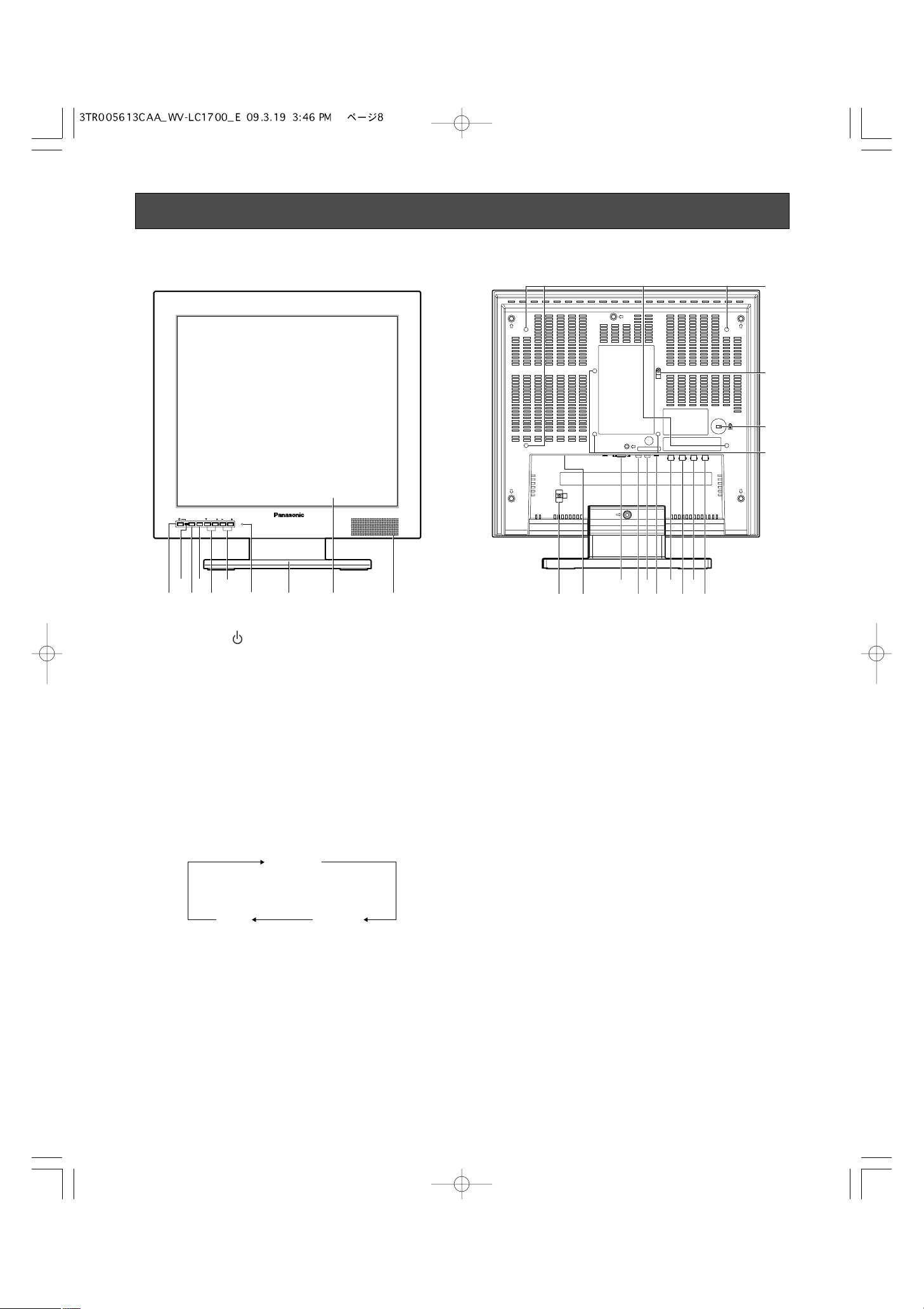
Major Operating Controls and Their Functions
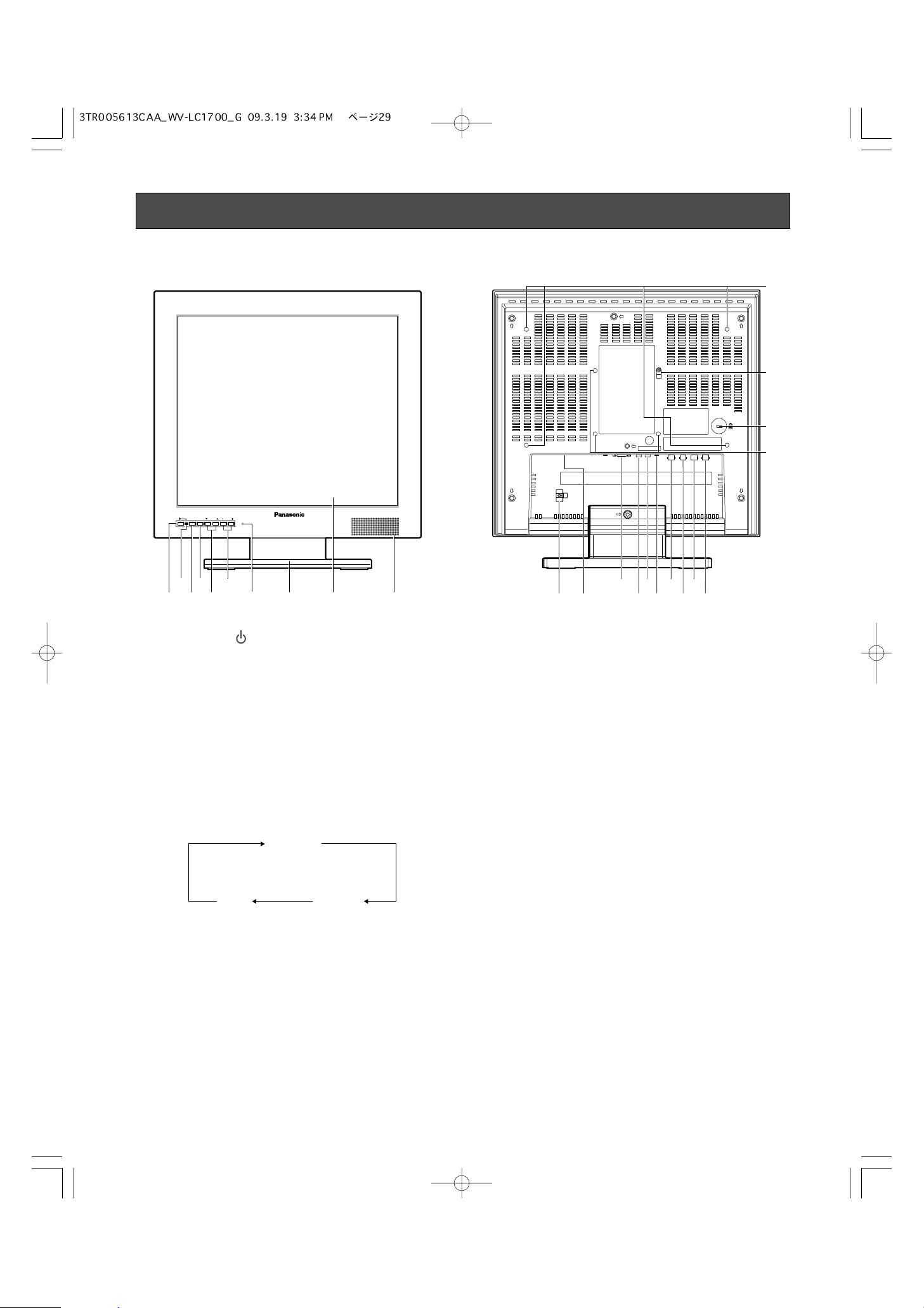
■ Front View
i
!3
!1 !4!5!6!7!8!9@0
@1
@4
@2
@3
!2
■ Rear View
q Power button
Powers on or off the monitor.
Note: Power is supplied from the connected cable even
while the monitor is OFF.
w Power indicator
This indicator lights green while power is supplied to the
monitor. Even though the monitor power is turned off, it
lights in red while the power supply is available.
e Input signal selection button (INPUT SELECT)
Every pressing this button can change input signals as
follows.
r Menu button (MENU)
• Displays the VIDEO ADJUST menu.
• Determines the selected parameter in setup menus.
t Selection buttons (SELECT: C, D)
These buttons move the cursor in setup menus.
y Audio buttons (AUDIO: +, –)
These buttons adjust the audio volume level. These buttons increments or decrements the selected parameter
in setup menus.
u Reset switch
Provideds restart this unit as necessary.
i Monitor stand
o LCD panel
Note: Take care not to pinch your hands or fingers
between the LCD panel and the monitor stand.
!0 Speaker
!1 Power cord clamp
After the power cord has been connected, remove the
screw that is used to mount the power cord clamp and
fasten the power cord.
!2 Power input jack (AC IN)
Connect the power cord (accessory).
!3 PC input connector (PC IN)
Accepts an analog RGB signal from a PC.
Note: For timing data this connector supports, refer to
p. 9 "Timing data chart for PC input".
!4 Audio input connector (AUDIO IN)
With an audio cable connection, this connector accepts
an audio signal from an external device and supplies the
signal to the built-in speaker.
!5 Audio output connector (AUDIO OUT)
Supplies an audio signal accepted by the AUDIO IN
connector to another external device.
w
q
INPUT
MENU SELECT AUDIO
SELECT
r y
et
u
Video Monitor WV-LC1900
o !0
PC
VIDEO A
VIDEO B/
S-VIDEO
9
!6 S-video input connector (S-VIDEO IN)
Accepts an S-video signal from an external device.
Note: This connector and the VIDEO-B IN connector is
connected to the same device. When an S-video
signal and composite video signal are supplied from
a device at the same time, the S-video signal is
accepted by priority.
!7 Video input B connector (VIDEO-B IN)
Accepts a composite video signal from an external
device.
!8 Video output B connector (VIDEO-B OUT)
Supplies a composite video signal accepted by the
VIDEO-B IN connector to another external device.
!9 Video input A connector (VIDEO-A IN)
Accepts a composite video signal from an external
device.
@0 Video output A connector (VIDEO-A OUT)
Supplies a composite video signal accepted by the
VIDEO-A IN connector to another external device.
@1 Screw holes for rack mount bracket (☞ page 10)
@2 Fall prevention clamp
Using the clamp with strong wire or chain (commercially
available), secure the monitor to a sufficiently strong wall
or pillar for fall prevention.
When a wall mounting bracket is used, remove the
clamp.
@3 Security slot
You can attach a lock that meets the industry standard
specification (3 to 3.26 mm x 7 to 7.26 mm x 3.5 to
4 mm) {0.12" x 0.28" x 0.15"}.
@4 Screw holes for wall mount bracket (☞ page 11)
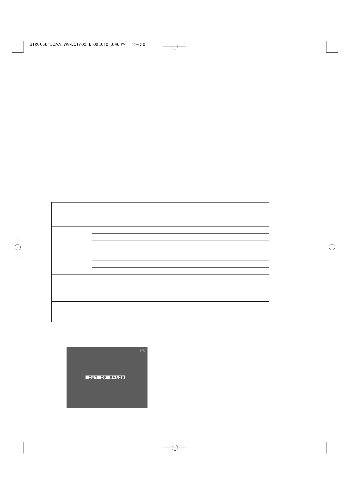
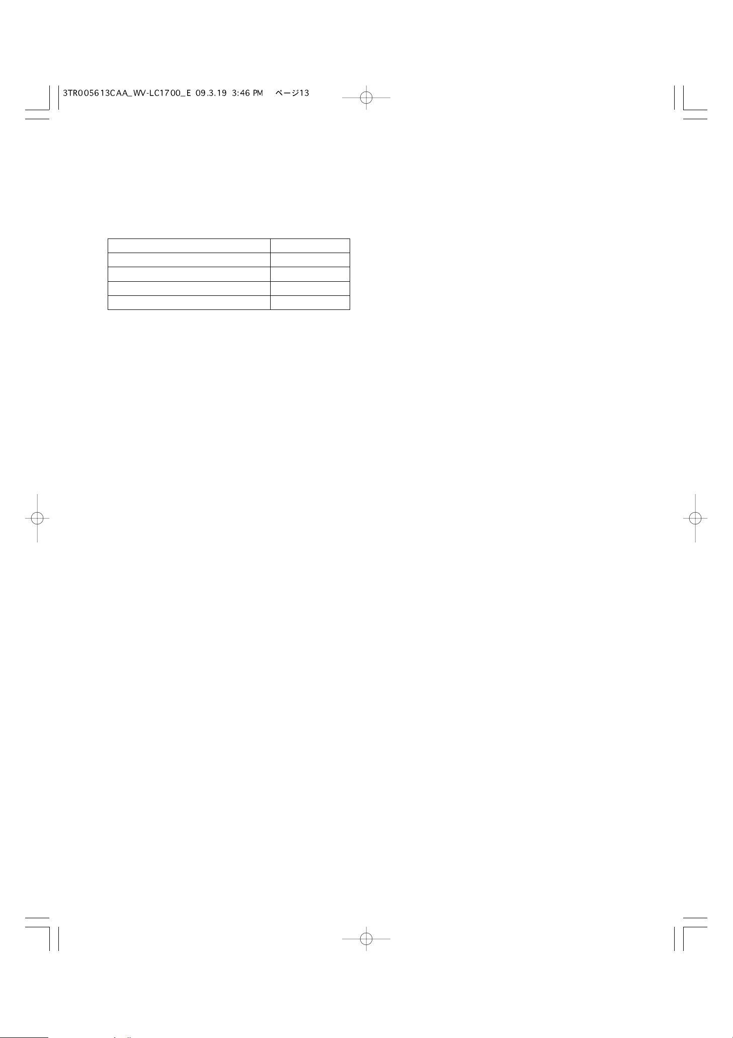
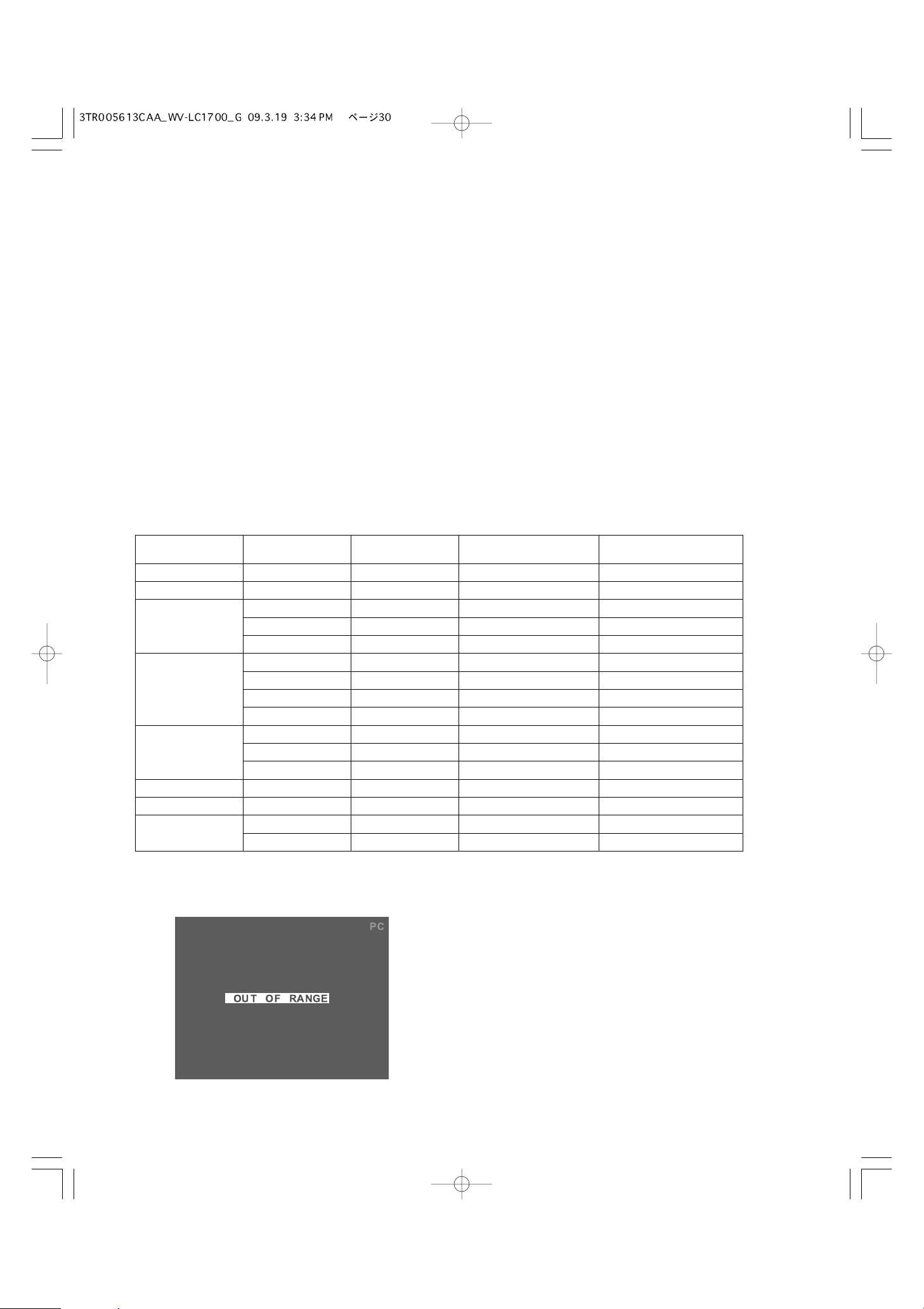
Timing data chart for PC input
This monitor supports the timing data listed as follows.
Note:
• If an input signal does not meet the standards (dot clock frequency, horizontal frequency, and vertical frequency), "OUT OF
RANGE" will appear on the screen.
• This monitor does not support plug-and-play.
Resolution Vertical
frequency (Hz)
Horizontal
frequency (kHz)
Dot clock
frequency (MHz)
Standards
31.500 VESA standard
VESA standard
Industry standard
VESA standard
VESA standard
VESA guideline
VESA guideline
VESA standard
VESA standard
VESA guideline
VESA standard
VESA standard
VESA standard
VESA standard
VESA standard
VESA standard
37.985640 x 400
35.50037.985720 x 400
25.175
31.500
31.5
37.9
60
72
640 x 480
31.50037.575
36.00035.156
800 x 600
40.00037.960
50.00048.172
49.50046.975
65.00048.460
1024 x 768
75.00056.570
78.75060.075
108.00067.5751152 x 864
108.00060.0601280 x 960
108.000
135.000
64.0
80.0
60
75
1280 x 1024
10
Installations
WARNING
The installations described in the figures should be made by qualified service personnel or system installers.
Caution: Attach this monitor to a flat wall with a locally procured mounting bracket. After the installation, secure the monitor to
prevent dropping.
Important:
• Do not block the ventilation opening or slots on the cover.
• Do not mount the monitor on places subject to constant vibrations. That may cause trouble or damage.
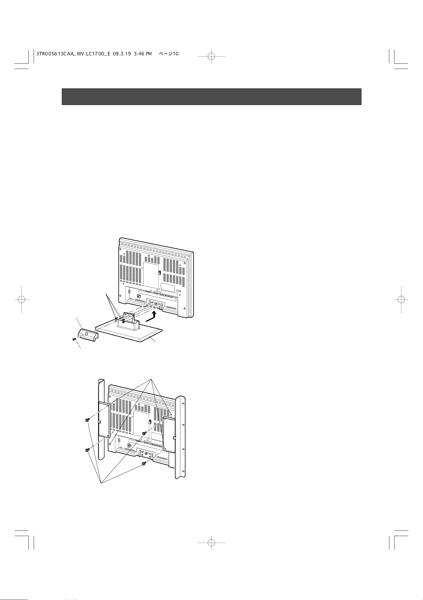
■ Installation this monitor in a rack
Use the rack mount bracket WQ-LM191 (option) and the rack mounting screws (locally procured) to install this unit in a rack.
z Remove the screw of stand cover (M4), and then
remove the stand cover.
x Remove the four screws of monitor stand (M4), and then
remove the monitor stand.
Note:
The removed stand cover, monitor stand and screws
should be retained for future use.
c Install the rack mount brackets on the rear of the moni-
tor.
Fix the rack mount brackets firmly using four fixing
screws (provided) (M4).
Stand cover
Screws (M4)
Screw (M4)
Monitor stand
Screw holes for rack mount bracket
Screws (M4)

11
v Install this unit in the rack.
Fix this unit firmly using eight mounting screws (locally
procured).
b Adjust the angle of this unit.
The angle can be adjusted from 0 ° down to 20 °.
Important:
During angle adjustments, be careful not to pinch your hand or fingers in the gap. Never press the LCD panel.
Notes on the screw holes for wall mount bracket
• Check how heavy the wall mount bracket and this unit are.
• Examine the strength of the area on the wall where the monitor is to be mounted, and the pull-out strength should be more
than 5 times the total weight of the wall mount bracket and this unit.
Rack mounting screws
(locally procured)
12
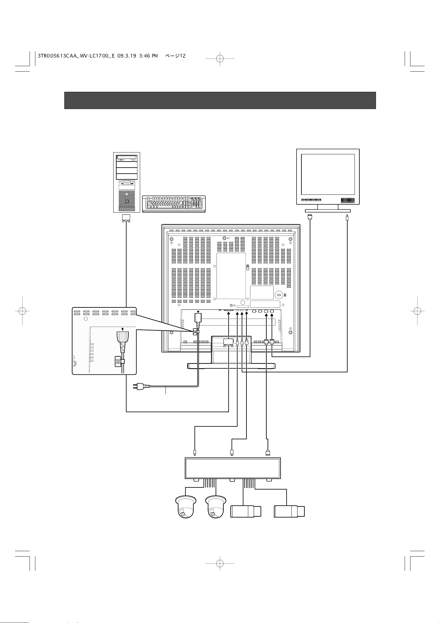
Connections
■ Connection Example
PC
Other video monitors
Monitor output
(VGA)
* Be sure to secure the
power cord with a power
cord clamp.
Audio inputVideo input
Power cord
(supplied)
Digital disk recorder
Audio
output
S-video
output
Video
output
13
■ Camera Connection
Connect the video output connector of camera to the VIDEO
IN connector with a coaxial cable.
Note: Make sure that the cable length between the camera
and monitor is as follows.
■ Connection with Two or More
Video Monitors
• Connect the VIDEO OUT connector of this monitor to the
video input connector of another monitor with a coaxial
cable.
• Connect the AUDIO OUT connector of this monitor to the
audio input connector of another monitor with an audio
cable.
Note:
• Up to 10 monitors can be connected to this monitor. If
11 or more monitors are connected, picture quality may
be degraded.
• Total length of each cable should not exceed 150 m.
■ Digital Disk Recorder
Connection
● To Perform Recording
• Connect the VIDEO OUT connector of this monitor to the
video input connector of digital disk recorder (or other
recording devices) with a coaxial cable.
• If necessary, connect the AUDIO OUT connector of the
monitor to the audio input connector of digital disk
recorder (or other recording devices) with an audio
cable.
● To Perform Playback
Do either of the following.
• Connect the VIDEO IN connector of this monitor to the
video output connector of digital disk recorder (or other
recording devices) with a coaxial cable.
• Connect the S-VIDEO IN connector of this monitor to the
S-video output connector of digital disk recorder (or
other recording devices) with an S-video cable.
● To Output Audio Signal
Connect the AUDIO IN connector of this monitor to the audio
output connector of digital disk recorder (or other recording
devices) with an audio cable.
■ PC Connection
Connect the PC IN connector of this monitor to the analog
RGB output connector of PC (or another device).
Check the room around the PC IN connector at the rear and
procure a suitable 15-pin Mini D-sub connector cable before
the cable connection.
Cable type
RG-59/U 3C-2V
RG-6/U 5C-2V
RG-11/U 7C-2V
RG-11/U 10C-2V
Cable length
250 m
500 m
600 m
800 m
14
Before operation, check the connections between monitors
and external devices (cameras, digital disk recorders, etc.)
(Refer to p. 12)
1. Press the power button. The monitor will be powered on,
and the power indicator will light up in green.
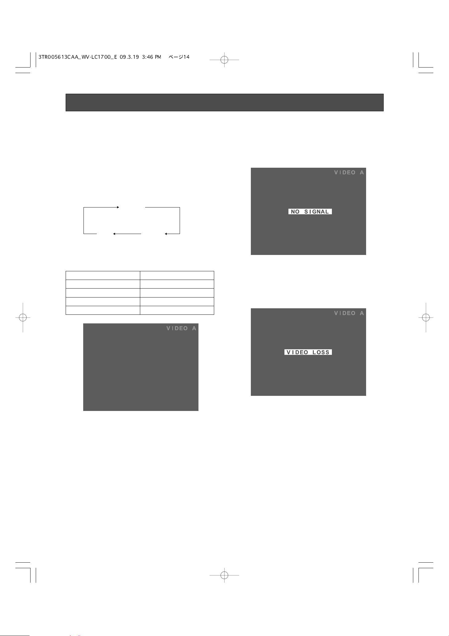
2. Press the INPUT SELECT button.
Every pressing this button can change input signals as
follows.
The signal name will be displayed on the upper right
corner of screen for 3 seconds.
Note:
• When no input signal is supplied to the monitor, "NO
SIGNAL" will be displayed on the screen.
"NO SIGNAL" will continue to be displayed until an input
signal is supplied.
• When the loss of input signal is detected due to cable
disconnection, etc., "VIDEO LOSS" will be displayed on
the screen.
"VIDEO LOSS" will continue to be displayed until a cable
is connected.
• When the PC input signal is selected and picture display
position is not proper, perform the output setting of the
connected PC. (Refer to the diagram in p. 9.)
Power-On
Signal name Input signal type
VIDEO A Composite video A
VIDEO B Composite video B
S-VIDEO S-video
PC PC (Analog RGB)
PC
VIDEO A
VIDEO B/
S-VIDEO
15
Audio Volume Control
Video Adjustment and Setup
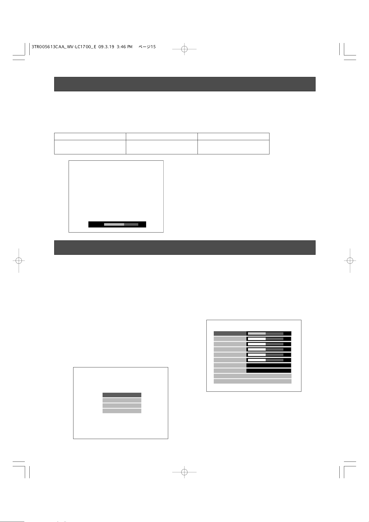
By pressing the + or – button during picture display, you can adjust the audio volume level. While the + or – button is pressed,
the volume level is displayed on the screen.
–: Audio volume level goes down.
+: Audio volume level goes up.
■ Video Adjustment (Video Input,
S-Video Input)
Setup of this monitor will be performed in the VIDEO
ADJUST menu.
Note:
• The menu title display differs depending on the selected
input signal. Before adjustment, press the INPUT
SELECT button surely to select the input signal. (Refer to
p. 13.)
• If the power is shut down during setup, the setting values will not be saved.
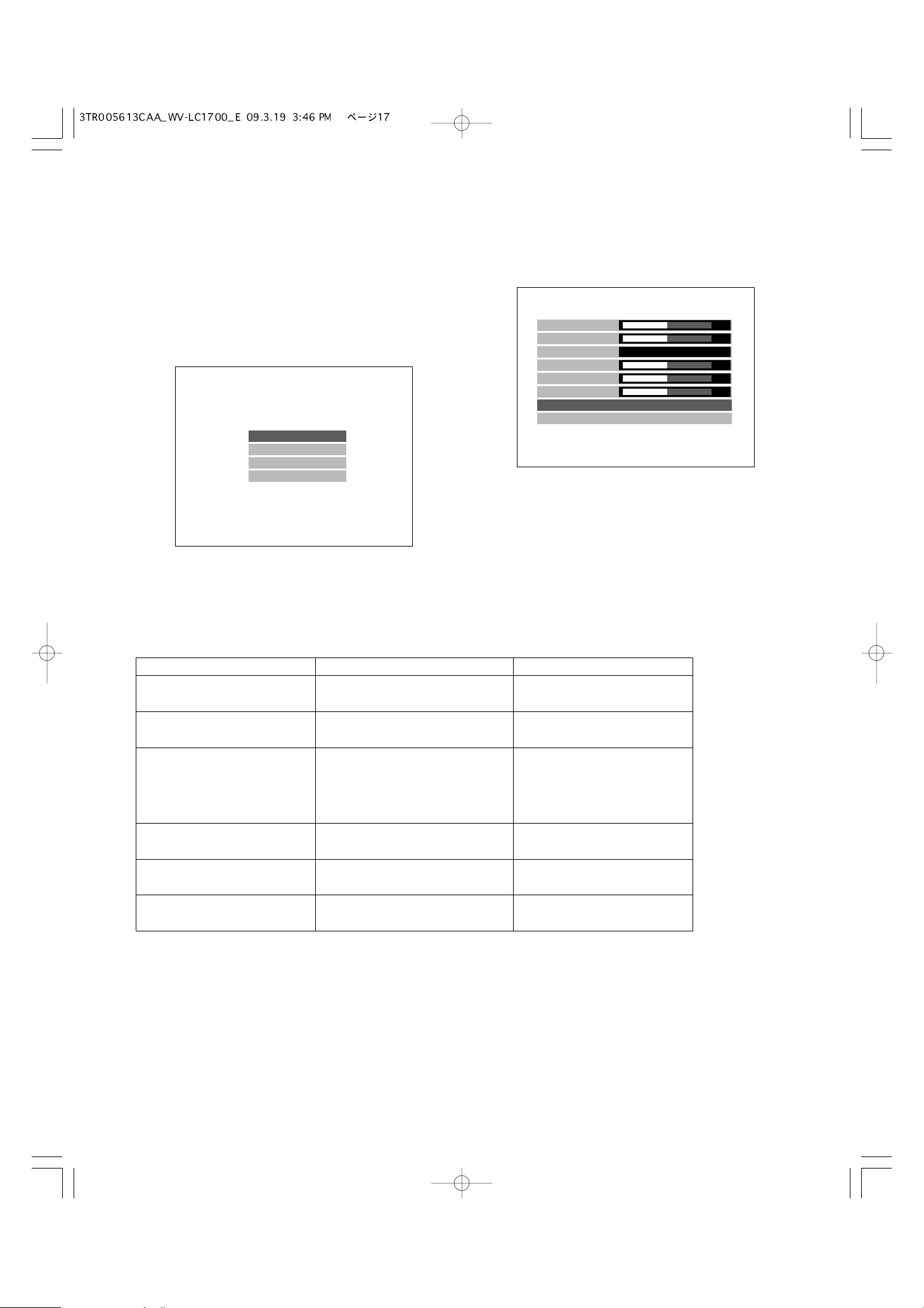
1. Press the MENU button. The top menu will be displayed.
2. Move the cursor to VIDEO ADJUST by pressing the C or
D button. Press the MENU button.
The VIDEO ADJUST menu will be displayed.
Present input signals are displayed in the menu title.
For video input (A): VIDEO A
For video input (B): VIDEO B
For S-video input: S-VIDEO
To the right side of the menu title, the input signal type is
displayed as specified below.
NTSC: When a video signal input of the NTSC system is
entered or if there is no signal
PAL: When a video signal input of the PAL system is
entered
Setting item Effect Setting value
VOLUME +: Audio volume level goes up.
–: Audio volume level goes down.
0 to +40
VOLUME
22
VIDEO ADJUST
P C S E T U P
LANGUAGE
E X I T
VIDEO B IN
BRIGHTNESS
CONTRAST
SHARPNESS
COLOR
TINT
H-POSITION
COLOR TEMP
SCAN
NORMAL SETTINGS
EXIT
6500K
FULL
NTSC
00
00
00
00
00
00
16
Setting item
Note:
• The respective setting items are allowed to set up different values in regard to each input signal. However, the same values
are used in common for the video input B and S-video input.
• "TINT" can be adjusted only if the input signal is of the NTSC system.
3. Move the cursor to the following setting items by pressing the C or D button. Then, adjust the levels by pressing the + or –
button.
Note: Value can be set differently for each input signal.
4. To reset the settings, move the cursor to NORMAL SETTINGS by pressing the C or D button. Press the MENU button.
The currently displayed input signal (VIDEO A, VIDEO B, or S-VIDEO) currently selected will be reset to the factory default.
5. To return to the top menu, move the cursor to EXIT by pressing the C or D button. Then, press the MENU button.
6. After returning to the top menu, move the cursor to EXIT by pressing the C or D button. Then, press the MENU button.
The monitor display return to the default status.
Note: If no operation has been performed for 10 seconds or more, the monitor display returns to the default status.
Effect Setting value
BRIGHTNESS
CONTRAST +: Contrast level goes up.
–: Contrast level goes down.
–20 to +20
SHARPNESS +: Picture quality becomes sharper.
–: Picture quality becomes softer.
–7 to +7
COLOR +: Color density level goes up.
–: Color density level goes down.
–20 to +20
TINT (NTSC system only)
H-POSITION
COLOR TEMP
SCAN
+: Tint becomes more greenish.
–: Tint becomes more reddish.
+: Position is moved to the right.
–: Position is moved to the left.
–20 to +20
–10 to +10
6500K: Reddish color is intensi-
fied (default).
9300K: Blue color is intensified.
FULL:
The overall video image is displayed throughout the screen.
The aspect ratio of the video
image is disregarded and the
displayed image appears
somewhat slender.
OVER:
The screen height and the
image height are joined to display. Since the enlarged
aspect ratio remains to be 1:1,
the right and left parts of the
image are slightly lost.
UNDER:
The screen width and the
image width are joined to display. Since the enlarged
aspect ratio remains to be 1:1,
black strips are displayed in
the top and bottom parts of
the image.
+: Brightness level goes up.
–: Brightness level goes down.
–20 to +20
17
3. Move the cursor to the following setting items by pressing the C or D button. Then, adjust the levels by pressing the + or –
button.
■ Video Adjustment (PC Input
Connector)
1. Adjustment of this monitor will be performed in the
VIDEO ADJUST menu.
Note: The menu title display differs depending on the
selected input signal. Before adjustment, press the
INPUT SELECT button surely to select the input signal.
(☞ Page 8)
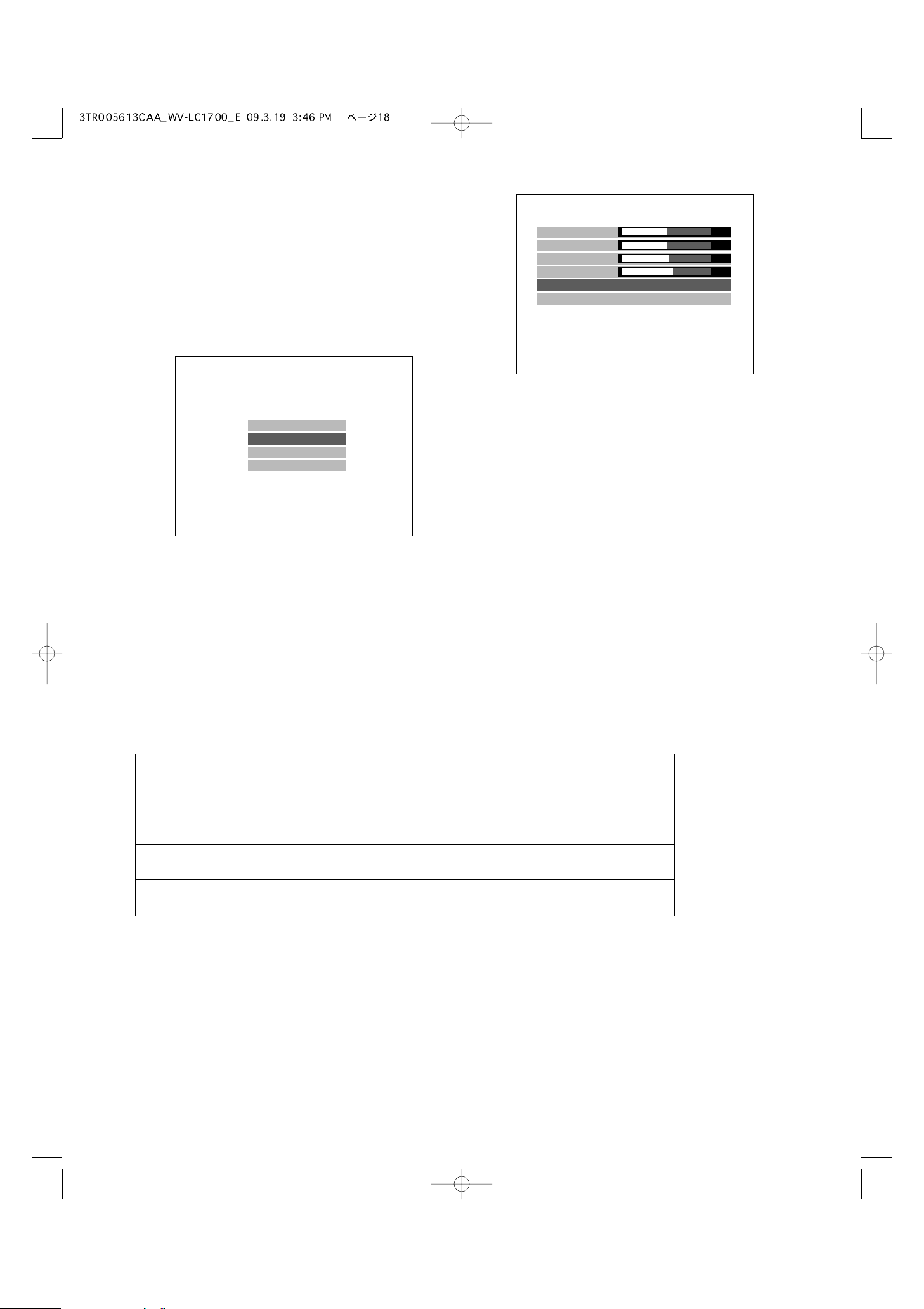
2. Move the cursor to VIDEO ADJUST by pressing the C
or D button. Press the MENU button. The VIDEO
ADJUST menu will be displayed.
Present input signals are displayed in the menu title.
For PC input: PC IN
According to the timing data table (☞ page 9), present
signals are displayed in the following position of the
menu title in the format of [Resolution@Refresh rate
(Vertical frequency)].
Setting item Effect Setting value
BRIGHTNESS
CONTRAST +: Contrast level goes up.
–: Contrast level goes down.
–20 to +20
COLOR TEMP 6500K: Red is intensified
(default).
9300K: Blue is intensified.
USER: User colors (R/G/B) are
adjustable.
USER COLOR-R +: Red density level goes up.
–: Red density level goes down.
–20 to +20
USER COLOR-G +: Green density level goes up.
–: Green density level goes down.
–20 to +20
USER COLOR-B +: Blue density level goes up.
–: Blue density level goes down.
–20 to +20
+: Brightness level goes up.
–: Brightness level goes down.
–20 to +20
Note: USER COLOR-R, USER COLOR-G, and USER COLOR-B can be adjusted only if USER has been chosen for COLOR
TEMP.
4. To reset the settings, move the cursor to NORMAL SETTINGS by pressing the C or D button. Press the MENU button.
The currently displayed input signal (PC input) currently selected will be reset to the factory default.
5. Select EXIT, and press the MENU button. The top menu will be displayed.
6. Select EXIT on the top menu, and press the MENU button. The monitor display return to the default status.
Note: If no operation has been performed for 10 seconds or more, the monitor display returns to the default status.
VIDEO ADJUST
P C S E T U P
LANGUAGE
E X I T
PC IN 1280 x 1024@60 Hz
BRIGHTNESS
CONTRAST
COLOR TEMP
USER COLOR-R
USER COLOR-G
USER COLOR-B
NORMAL SETTINGS
EXIT
6500K
00
00
00
00
00
18
Setting item
4. Move the cursor to the following setting items by pressing the C or D button. Then, adjust the levels by pressing the + or –
button.
Effect Setting value
H-POSITION
V-POSITION
CLOCK
PHASE
+: Screen moves upwards.
–: Screen moves downwards.
+: Clock is enlarged.
–: Clock is contracted.
+: Phase is increased.
–: Phase is decreased.
–20 to +20
–20 to +20
0 to +63
+: Screen moves to the right.
–: Screen moves to the left.
–40 to +40
■ Setting of PC Input
While the PC input signal is being selected, you can adjust
the horizontal position and vertical position.
Note: Since this unit detects input signals and makes auto-
matic adjustments as required, this setting is not
required in ordinary cases.
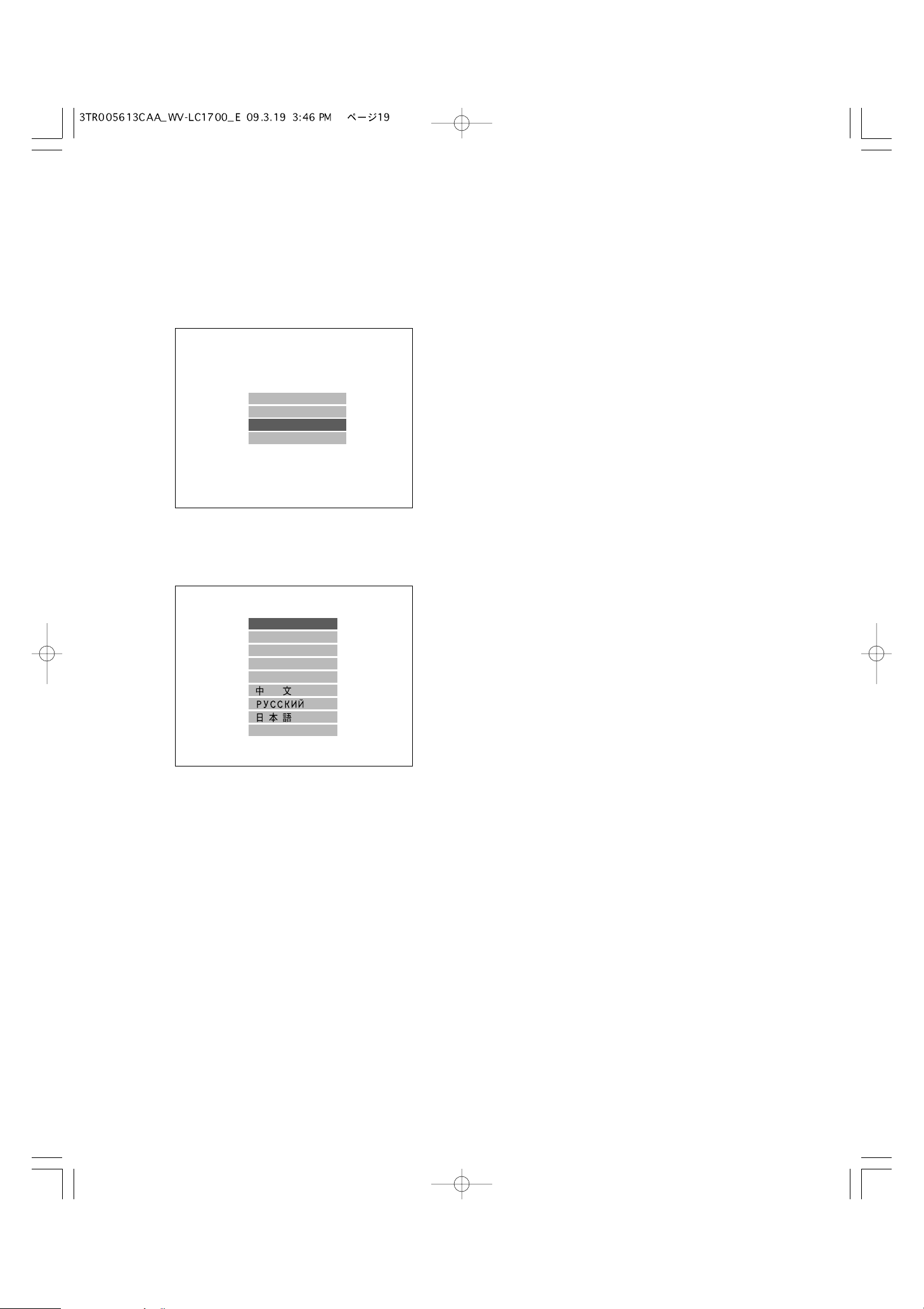
1. Press the MENU button. The top menu will be displayed.
2. Move the cursor to PC SETUP by pressing the C or D
button. Press the MENU button. The PC SETUP menu
will be displayed.
Present input signals are displayed in the menu title.
For PC input terminal: PC IN
According to the timing data table (☞ page 9), present
signals are displayed at the right side of the menu title in
the format of [Resolution@Refresh rate (Vertical frequency)].
3. Move the cursor to AUTO by pressing the C or D but-
ton. Press the MENU button. The image display position
will be adjusted automatically.
Note:
• The screen flickers during automatic adjustments. This
is, however, not a malfunction.
• According to the situation of video signals, it takes several seconds to 10-odd seconds to complete automatic
adjustments.
If an optimal screen cannot be obtained after automatic
adjustments, further operation specified below may be
needed.
5. Select EXIT, and press the MENU button. The top menu will be displayed.
6. Select EXIT on the top menu, and press the MENU button. The monitor display return to the default status.
Note:
• If no operation has been performed for 10 seconds or more, the monitor display returns to the default status.
• Check if the VGA output setting has been performed for the connected PC. (Refer to p. 9.)
• This monitor does not support plug-and-play. Depending on the connected PC, the PC SETUP menu can be controlled from
the PC keyboard. However, proper adjustment is not supported.
VIDEO ADJUST
P C S E T U P
LANGUAGE
E X I T
PC IN 1280 x 1024@60 Hz
H-POSITION
V-POSITION
CLOCK
PHASE
AUTO
EXIT
+01
+38
00
00
19
■ Language Setup
You can select the language for monitor display.
Note: If the power is shut down during setup, the setting val-
ues will not be saved.
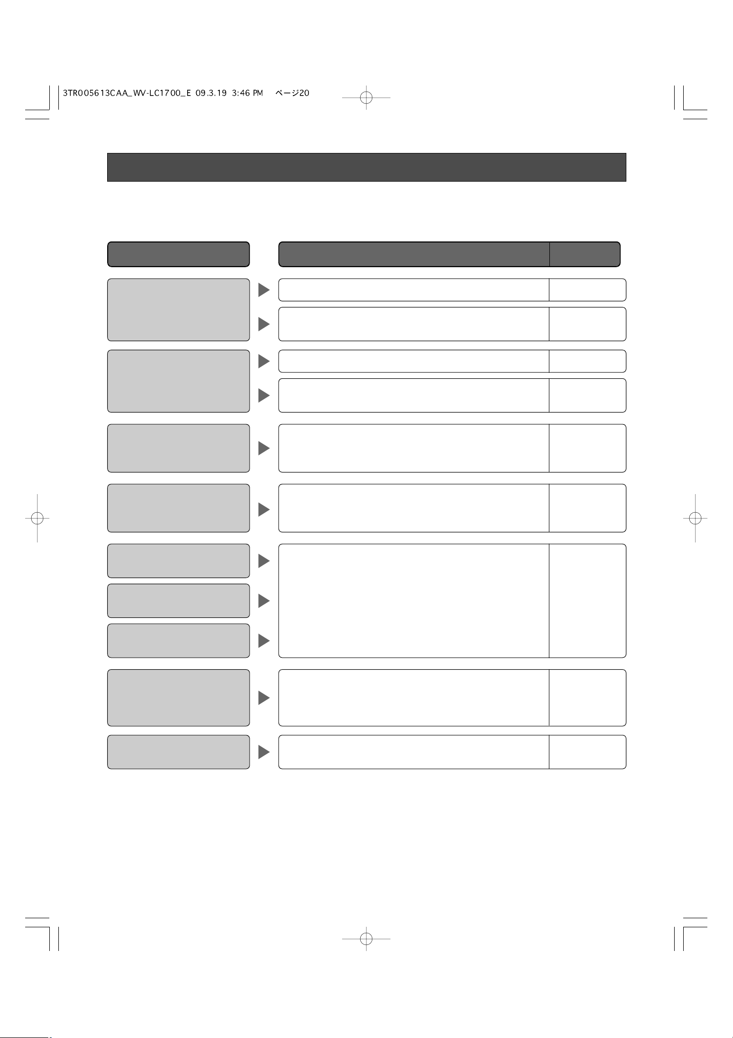
1. Press the MENU button. The top menu will be displayed.
2. Move the cursor to LANGUAGE by pressing the C or D
button. Press the MENU button. The LANGUAGE menu
will be displayed.
3. Move the cursor to the desired language by pressing
the C or D button. Press the MENU button. The selected language will be applied for monitor display.
4. Select EXIT, and press the MENU button. The top menu
will be displayed.
Note: When any language other than Japanese is selected,
the menu title and the statement of [Return] will be
turned into notation of the selected language.
5. Select EXIT on the top menu, and press the MENU button. The monitor display return to the default status.
Note: If no operation has been performed for 10 seconds or
more, the monitor display returns to the default status.
VIDEO ADJUST
P C S E T U P
LANGUAGE
E X I T
LANGUAGE
ENGLISH
FRANÇAIS
DEUTSCH
ESPAÑOL
ITALIANO
EXIT
20
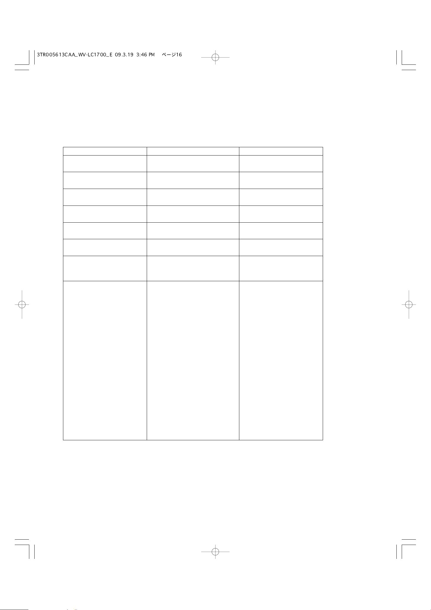
Troubleshooting
Check the following before requesting repair.
If a trouble cannot be corrected even after checking and trying remedy, contact your dealer.
Check if the power plug is properly connected to the AC outlet.
Power is not turned on.
"NO SIGNAL" appears on the
screen, and no image is displayed.
"OUT OF RANGE" appears on
the screen, and no picture is
displayed.
Picture display position is not
proper while the PC input signal
is being selected.
The power cord insulation is
damaged.
The power cord, plug and connectors get hot during use.
The power cord gets hot when
bent or stretched.
–
Check if the power plug is properly inserted into the AC IN jack
of this monitor.
–
Check the cables are properly inserted into the connectors. 8 - 9, 13
Check if the cable connection is corresponding with the selected
input signal.
8 - 9, 13
When the PC input signal does not meet the standards of this
monitor, no picture is displayed.
→ Check the specifications of connected PC.
9, 18
Perform auto adjustment on the PC menu. If the picture display
position is not properly adjusted, perform manual adjustment.
18
The power cord, plug and connectors are worn out.
If you continue to use it, a fire or an electric shock may occur.
Unplug the power cord immediately, and refer servicing to qualified service personnel.
–
Reference
pages
Cause/solution
Symptom
"VIDEO LOSS" appears in the
center of the screen, and no
image is displayed.
No reaction is observed by
pressing the front buttons.
Check whether the cable is appropriately connected.
Check whether the external devices such as the camera are
turned on.
Press the reset switch to restart this unit.
8 - 9
8 - 9
21
Specifications
Power source: 100 V to 240 V AC, 50 Hz
Power consumption: 43 W (WV-LC1700), 46 W (WV-LC1900)
Display panel: 17" (WV-LC1700), 19" (WV-LC1900) TFT LCD, built-in dual CCFT's
Display area: 337 mm (H) x 270 mm (V) (WV-LC1700)
376 mm (H) x 301 mm (V) (WV-LC1900)
Number of pixels: 1 280 x 1 024 (SXGA)
Aspect ratio: 5 : 4
Maximum brightness: 300 cd/m
2
(typical)
Maximum contrast ratio: 800 : 1 (typical)
Display colors: Approx. 16 700 000
Viewing angle (L/R/U/D): 80 °/80 °/75 °/85 ° (contrast ratio 10 : 1, typical)
TV mode: Composite video input / Y/C video input: NTSC/PAL (auto)
Horizontal resolution: 500 or more TV lines
Video input
(VIDEO-A IN, VIDEO-B IN): 1.0 V [P-P]/75 Ω (BNC), composite video signal
Video output
(VIDEO-A OUT, VIDEO-B OUT): Auto-termination loop-thru (BNC)
S-video input (S-VIDEO IN): Y=1.0 V [P-P]/75 Ω, C= 0.3 V [P-P]/75 Ω, mini DIN jack
PC input (PC IN): RGB, 0.7 V [P-P]/75 Ω, horizontal and vertical timing pulse: TTL, 15-pin mini D-sub
connector
Speaker output: 0.5 W
Audio input: –8 dB/Hi-Z, RCA pin jack
Audio output: Loop-thru output, RCA pin jack
Ambient operating temperature: 0 °C to +40 °C
Ambient storage temperature: –20 °C to 60 °C
Ambient operating humidity: Less than 90 %
Screw holes for VESA mounting bracket: 100 mm pitch, VESA standard
Dimensions: WV-LC1700: 404 mm (W) x 415 mm (H) x 236 mm (D) (including the monitor stand)
404 mm (W) x 365 mm (H) x 77 mm (D) (excluding the monitor stand)
WV-LC1900: 423 mm (W) x 440 mm (H) x 236 mm (D) (including the monitor stand)
423 mm (W) x 390 mm (H) x 80 mm (D) (excluding the monitor stand)
Weight: WV-LC1700: 7 kg (including the monitor stand)
5.7 kg (excluding the monitor stand)
WV-LC1900: 7.5 kg (including the monitor stand)
6.2 kg (excluding the monitor stand)
Operating Instructions (This Document) .......................... 1 pc.
Power Cord ...................................................................... 2 pcs.
Standard Accessories
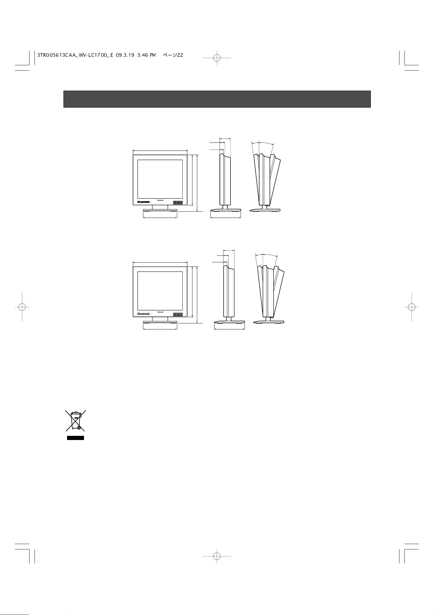
22
(Unit: mm)
WV-LC1700
WV-LC1900
Appearance
Information on Disposal for Users of Waste Electrical & Electronic Equipment (private households)
This symbol on the products and/or accompanying documents means that used electrical and electronic products should not be
mixed with general household waste.
For proper treatment, recovery and recycling, please take these products to designated collection points, where they will be
accepted on a free of charge basis. Alternatively, in some countries you may be able to return your products to your local retailer
upon the purchase of an equivalent new product.
Disposing of this product correctly will help to save valuable resources and prevent any potential negative effects on human health
and the environment which could otherwise arise from inappropriate waste handling. Please contact your local authority for further
details of your nearest designated collection point.
Penalties may be applicable for incorrect disposal of this waste, in accordance with national legislation.
For business users in the European Union
If you wish to discard electrical and electronic equipment, please contact your dealer or supplier for further information.
Information on Disposal in other Countries outside the European Union
This symbol is only valid in the European Union.
If you wish to discard this product, please contact your local authorities or dealer and ask for the correct method of disposal.
INPUT
SELECT
404
MENU SELECT AUDIO
INPUT
MENU SELECT AUDIO
SELECT
Video Monitor WV-LD1700
Video Monitor WV-LC1700
265 236
365
415
77
41
5°
15°
28
INPUT
SELECT
MENU SELECT AUDIO
INPUT
MENU SELECT AUDIO
SELECT
423
265
Video Monitor WV-LD1700
Video Monitor WV-LC1900
390
440
80
50
5°
15°
30
236
23
VORSICHT:
Bevor Sie dieses Produkt anschließen oder in Betrieb nehmen,
bitte das Schild auf der Unterseite durchlesen.
WARNUNG:
• Dieses Gerät muss geerdet werden.
• Das Gerät ist an eine Netzsteckdose mit Schutzerdung anzuschließen.
• Der Netzstecker oder die Gerätekupplung muss stets angeschlossen bleiben.
• Das Gerät sollte vor Regen und Feuchtigkeit geschützt werden,
um der Gefahr eines Brandes oder elektrischen Schlags vorzubeugen.
• Das Gerät sollte vor Tropf- und Spritzwasser geschützt und
keine Flüssigkeiten enthaltende Gefäße wie Vasen darauf
abgestellt werden.
• Alle mit der Installation dieses Produktes verbundenen Arbeiten
sollten von qualifiziertem Kundendienstpersonal oder Systeminstallateuren vorgenommen werden.
• Anschlüsse müssen den örtlichen elektrotechnischen Vorschriften entsprechen.
Wir erklären in alleiniger Verantwortung, daß das Produkt, auf das sich
diese Erklärung bezieht, mit der folgenden Normen oder normativen
Dokumenten übereinstimmt. Gemäß den Bestimmungen der Richtlinie
2006/95/EC und 2004/108/EC.
Das Blitzzeichen mit Pfeil im gleichseitigen
Dreieck soll den Benutzer auf das Vorhandensein von nichtisolierter "gefährlicher
Spannung" innerhalb des Gehäuses hiweisen, die so groß sein kann, daß sie Gefahr
eines elektrischen Schlags darstellt.
Das Ausrufezeichen im gleichseitigen Dreieck soll den Benutzer auf wichtige Bedienungs- und Wartungsanweisungen in den
Unterlagen hinweisen, die dem Gerät beiliegen.
Unterbrechen der Stromversorgung. Bei Geräten mit oder ohne
Netzschalter liegt Spannung am Gerät an, sobald der
Netzstecker an der Steckdose angeschlossen wird. Zum
Unterbrechen der gesamten Stromversorgung das Netzkabel
ziehen.
VORSICHT: WEDER DECKEL NOCH RÜCKPLATTE
ABNEHMEN, UM DIE GEFAHR EINES ELEKTRISCHEN
SCHLAGS ZU VERMEIDEN. DAS GERÄT ENTHÄLT
KEINE BAUTEILE, DIE VOM KUNDEN GEWARTET
WERDEN KÖNNEN.
CAUTION
RISK OF ELECTRIC SHOCK
DO NOT OPEN
DEUTSCHE AUSGABE
(GERMAN VERSION)
DEUTSCH
24
Wichtige Sicherheitsinstruktionen
1) Bitte lesen Sie diese Instruktionen aufmerksam durch.
2) Bewahren Sie die Instruktionen sorgfältig auf.
3) Befolgen Sie alle Warnungen.
4) Befolgen Sie alle Instruktionen.
5) Verwenden Sie dieses Gerät niemals in der Nähe von Wasser.
6) Reinigen Sie dieses Gerät nur mit einem trockenen Tuch.
7) Blockieren Sie nicht die Belüftungsöffnungen. Installieren Sie das Gerät gemäß den Instruktionen des Herstellers.
8) Installieren Sie dieses Gerät niemals in der Nähe von Wärmequellen wie Heizkörpern, Öfen oder anderen wärmeerzeugenden Apparten (einschließlich Verstärkern).
9) Umgehen Sie niemals die Schutzfunktion des gepolten oder geerdeten Netzsteckers. Ein gepolter Netzstecker weist zwei
Kontaktstifte auf, wobei ein Kontaktstift breiter als der andere ist. Ein geerdeter Netzstecker ist mit zwei Kontaktstiften und
einem dritten Erdungskontakt versehen. Der breite Stift bzw. der dritte Kontaktes dient der Sicherheit. Falls der mitgelieferte
Netzstecker nicht in Ihre Netzdose passt, wenden Sie sich an einen Elektriker, damit dieser die veralterte Netzdose
austauschen kann.
10) Achten Sie darauf, dass nicht auf das Netzkabel getreten oder dieses besonders an den Steckern, an der Netzdose bzw.
am Ausgang aus dem Gerät nicht eingeklemmt wird.
11) Verwenden Sie nur vom Hersteller vorgeschriebene/s Vorrichtungen/Zubehör.
12) Verwenden Sie dieses Gerät nur mit dem vom Hersteller vorgeschriebenen oder mit dem Gerät mitgelieferten Wagen,
Ständer, Stativ oder Tisch.
Bei Verwendung eines Wagens ist Vorsicht beim Transport des Geräts auf dem Wagen geboten, um ein Umkippen und die
damit verbundenen möglichen Verletzungen zu vermeiden.
13) Ziehen Sie den Netzstecker dieses Geräts bei Gewittern oder längerem Nichtgebrauch aus der Netzdose.
14) Überlassen Sie alle Wartungsarbeiten qualifiziertem Kundendienstpersonal. Wartungsarbeiten sind erforderlich, wenn das
Gerät auf irgendeine Weise beschädigt wurde, wie zum Beispiel bei defektem Netzkabel oder Netzstecker bzw. bei auf das
Gerät verschütteten Flüssigkeiten, in das Gerät eingedrungenen Gegenständen, wenn das Gerät Regen oder übermäßiger
Luftfeuchtigkeit ausgesetzt wurde, nicht richtig funktioniert oder fallen gelassen wurde.
S3125A
25
Beschränkung der Haftung
DIE LIEFERUNG DIESER PUBLIKATION ERFOLGT OHNE
MÄNGELGEWÄHR, WEDER AUSDRÜCKLICH NOCH STILLSCHWEIGEND, EINSCHLIESSLICH, ABER NICHT BESCHRÄNKT AUF DIE GESETZLICHE GEWÄHRLEISTUNG DER
GEBRAUCHSTAUGLICHKEIT, EIGNUNG ZU BESTIMMTEN
ZWECKEN ODER NICHTVERLETZUNG DER RECHTE
DRITTER.
Haftungsausschluss
Panasonic Corporation IST UNTER ANDEREM IN KEINEM
DER UNTEN AUFGEFÜHRTEN FÄLLE GEGENÜBER
JURISTISCHEN PERSONEN ODER PERSONEN HAFTBAR,
ES SEI DENN ES HANDELT SICH UM DEN ERSATZ ODER
DIE ZUMUTBARE WARTUNG DES PRODUKTS:
(1) SCHADENSANSPRÜCHE JEGLICHER ART, EINSCH-
LIESSLICH UND OHNE EINSCHRÄNKUNGEN
UNMITTELBARER, MITTELBARER, ZUSÄTZLICHER,
FOLGE- ODER ÜBER DEN VERURSACHTEN SCHADEN
HINAUSGEHENDER SCHADENSANSPRÜCHE;
(2) KÖRPERVERLETZUNGEN ODER SONSTIGE SCHÄ-
DEN, DIE AUF DEN UNSACHGEMÄSSEN GEBRAUCH
ODER DEN FAHRLÄSSIGEN BETRIEB DURCH DEN
BENUTZER ZURÜCKZUFÜHREN SIND;
(3) NICHT ZULÄSSIGES AUSEINANDERNEHMEN, REPA-
RIEREN ODER VERÄNDERN DES PRODUKTS DURCH
DEN BENUTZER.
DIE PUBLIKATION KÖNNTE TECHNISCHE UNGENAUIGKEITEN ODER DRUCKFEHLER ENTHALTEN.
IM LAUFE DER VERBESSERUNG DIESER PUBLIKATION
UND/ODER DER ENTSPRECHENDEN PRODUKTE KANN
DER INHALT JEDERZEIT KORRIGIERT BZW. ERGÄNZT
WERDEN.

26
INHALT
Wichtige Sicherheitsinstruktionen ....................................................................................................24
Beschränkung der Haftung ..............................................................................................................25
Haftungsausschluss .........................................................................................................................25
Vorwort .............................................................................................................................................27
Merkmale .........................................................................................................................................27
Vorsichtsmaßregeln .........................................................................................................................27
Wichtige Bedienungselemente und ihre Funktionen ........................................................................29
■ Vorderansicht .............................................................................................................................29
■ Rückansicht ................................................................................................................................29
Einbau ..............................................................................................................................................31
■ Installation des Monitors in einem Rack .....................................................................................31
Anschlüsse .......................................................................................................................................33
■ Anschlussbeispiel .......................................................................................................................33
■ Kamera-Anschluss .....................................................................................................................34
■ Anschluss von zwei oder mehr Video-Monitoren .......................................................................34
■ Digital-Diskrecorderanschluss ....................................................................................................34
■ Anschluss an einen PC ..............................................................................................................34
Einschalten .......................................................................................................................................35
Lautstärkeregler ...............................................................................................................................36
Video-Einstellungen und Setup ........................................................................................................36
■ Video-Einstellungen (Video-Eingang, S-Video-Eingang) ...........................................................36
■ Video-Einstellungen (PC-Eingangsstecker) ...............................................................................38
■ Einstellen des PC-Eingangssignals ...........................................................................................39
■ Einstellen der Sprache ...............................................................................................................40
Fehlersuche .....................................................................................................................................41
Technische Daten ............................................................................................................................42
Standardzubehör ..............................................................................................................................42
Äußeres ............................................................................................................................................43
27
Vorwort
Dieser Videomonitor ist mit einem 17-Zoll-(V)- oder einem
19-Zoll-(V)-LCD-Bildschirm ausgestattet (WV-LC1700 bzw.
WV-LC1900). Bei beiden Ausführungen werden ein I-PWandlerkreis mit Bewegungsfolgefunktion sowie ein 3D Y/CTrennschaltkreis eingesetzt, die qualitativ hochwertige
Bildanzeigen mit hoher Auflösung gewährleisten.
Merkmale
• Integriertes SXGA-Display mit kurzer Ansprechzeit und
hoher Auflösung.
• Composite-Videosignale, S-Videosignale und analoge
RGB-Signale für Tischcomputer (PC) werden unterstützt.
• Automatische Umschaltung auf NTSC- oder PAL-System
• Das PC-Display unterstützt Auflösungen von VGA (640 x
480) bis SXGA (1280 x 1024), wobei die Bildposition am
Display automatisch einjustiert wird.
• Audio-Eingangsanschluss x 1, Audio-Ausgangsanschluss x 1, sowie einen Lautsprecher-Ausgangsanschluss x 1 (max. 0,5 W)
• Bildschirmeingaben für das Setup-Menü
• Automatische Netzteil-Spannungseinstellung von 100
bis 240 V Wechselspannung
Hinweis: Das mitgelieferte Netzkabel kann nur für 220-
bis 240-V- Wechselspannung verwendet werden.
• Dieses Gerät kann unter Verwendung der als
Sonderausstattung erhältlichen Halterungen in einem
EIA-Standard-Rack montiert werden.
• Die Schraubenlöcher für die Wandmontagehalterungen
an der Rückseite entsprechen dem VESA*-Standard
(100 mm Abstand). Dieses Produkt kann mit Hilfe einer
im örtlichen Fachhandel erhältlichen Montagehalterung
an einer Wand montiert werden.
* VESA: Video Electronics Standards Association
(Verband für Videoelektronik-Standards)
Vorsichtsmaßregeln
• Alle mit der Installation dieses Produkts
verbundenen Arbeiten von qualifiziertem
Kundendienstpersonal oder Systeminstallateuren
vornehmen lassen.
• Die Entlüftungsöffnung oder Schlitze im Gehäuse
nicht blockieren.
• Verhindern, dass metallische Gegenstände durch die
Gehäuseschlitze ins Innere gelangen.
Dies könnte das Gerät permanent beschädigen. Sofort
die Stromversorgung ausschalten und das Gerät von
einem qualifizierten Kundendiensttechniker warten
lassen.
• Niemals das Produkt zerlegen.
Um elektrische Schläge zu vermeiden, niemals
Schrauben oder Abdeckungen entfernen.
Im Inneren befinden sich keine Teile, die vom Benutzer
gewartet werden können. Wartung nur von qualifiziertem Kundendienstpersonal vornehmen lassen.
• Das Gerät keinen Schlägen oder starken
Erschütterungen aussetzen.
Dadurch kann es beschädigt bzw. undicht werden.
• Das Gerät vor Nässe und Feuchtigkeit schützen.
Nicht versuchen, das Gerät in nasser Umgebung zu
betreiben.
Sofort für Abhilfe sorgen, falls das Gerät nass wird. Den
Strom ausschalten und Wartung von qualifiziertem
Kundendienstpersonal vornehmen lassen. Feuchtigkeit
kann das Gerät beschädigen und die Gefahr eines
elektrischen Schlags herbeiführen.

28
• Reinigung
Beim Reinigen des Geräts den Strom ausschalten.
Andernfalls kann es zu Verletzungen kommen.
Das Gerätegehäuse nicht mit ätzenden oder
scheuernden Mitteln reinigen.
Einen trockenen Lappen verwenden, um Schmutz vom
Gerät zu entfernen.
Bei hartnäckig anhaftendem Schmutz mit einem milden
Waschmittel vorsichtig abwischen.
• Das Gerät nicht außerhalb des vorgeschriebenen
Temperatur-, Luftfeuchtigkeits- und
Leistungsbereichs betreiben.
Das Gerät nur an Orten betreiben, an denen die
Temperatur innerhalb 0 °C und +40 °C und die Luftfeuchtigkeit unter 90 % liegt.
Die Versorgungsspannung für dieses Gerät beträgt
100 V Wechselstrom, 50 Hz.
* Das mitgelieferte Netzkabel kann nur für 220- bis 240-V-
Wechselspannung verwendet werden.
• Dieses Produkt nicht an Stellen montieren, die
konstanten Vibrationen ausgesetzt sind. Bei
Nichtbeachtung können Funktionsstörungen oder
Geräteschäden die Folge sein.
• Nur das mitgelieferte Netzkabel verwenden.
• Bei Nichtgebrauch sollte das Gerät unbedingt
weggeräumt werden.
• Die Oberfläche des LCD-Bildschirms ist mit einer
speziellen Beschichtung versehen.
Den Bildschirm vor Kontakt mit harten Gegenständen
schützen; keine Scheuermittel zum Abwischen verwenden.
Bei Nichtbeachtung können Kratzer und andere
Schäden am LCD-Bildschirm die Folge sein.
• Der LCD-Bildschirm ist ein Hochpräzisionsbauteil.
Das Vorhandensein von einigen hellen und dunklen
Stellen am Bildschirm ist durchaus normal.
Der Bildschirm ist in Ordnung, wenn 99,99 % aktive
Bildpunkte vorhanden sind.
• Wenn ein statisches Bild mit starken Kontrasten
über längere Zeit angezeigt wird, können danach
Geisterbilder zu sehen sein.
Dieses Phänomen ist auf die besonderen Eigenschaften
des LCD-Bildschirms zurückzuführen. Das Geisterbild
verschwindet nach einer gewissen Zeit wieder.
• Netzschalter
Durch das Ausschalten des Hauptschalters wird das
Gerät nicht vom Netz getrennt.
Wenn das Gerät für längere Zeit nicht verwendet werden
soll, muss das Netzkabel aus der Wandsteckdose
herausgezogen werden. Bei Verwendung eines Netzteils
die Stromversorgung des Netzteils ausschalten.
• Technische Angaben
Für die Identifikationsnummer des Produkts, die Versorgungsspannung und andere technische Angaben sich
auf den Aufkleber an der Geräterückseite beziehen.
• Erdung
Sich vergewissern, dass vor der Verwendung des
Geräts die Erdung korrekt ausgeführt wurde. Wenn ein
Erdungsanschluss verwendet wird, muss darauf
geachtet werden, dass der Erdwiderstand 100 Ohm
oder weniger beträgt.
• Stromversorgung
Sich vergewissern, dass der Erdungsanschluss
vorgenommen wurde, bevor der Netzstecker dieses
Geräts mit der Hauptstromversorgung verbunden wird.
Wenn erforderlich, muss auch der Erdungsanschluss
unterbrochen werden, nachdem der Netzstecker des
Geräts aus dem Hauptstromversorgungsnetz abgezogen wurde. Für das Netzkabel muss eine der nachfolgenden Unterbrechungsmethoden gewählt werden:
• Eine Stromversorgungs-Steuereinheit
• Eine direkte ausfallsichere Verbindung zwischen
Netzstecker und Steckdose
• Ein Anschluss des Netzkabels am Unterbrecher,
wobei der Kontaktabstand 3,0 mm oder mehr
betragen muss. Der Unterbrecher muss so
konstruiert sein, dass beim Aktivieren alle Leitungen
zwischen dem Hauptstromversorgungs-Netz und
diesem Produkt stillgelegt werden, mit Ausnahme
des Erdungsanschlusses.
• Einbaustelle
• Dieses Produkt ist für die Verwendung im
Gebäudeinnern vorgesehen. Das Produkt ist für
einen Betrieb im Freien nicht geeignet.
• Beim Einbau ist ein Freiraum von ungefähr 5 cm
über und hinter dem Gerät sowie auf beiden Seiten
einzuhalten.
• Dieses Produkt muss an einer Stelle installiert
werden, die frei von Vibrationen ist. Beim Aufstellen
an Orten mit Vibrationen hat dies Funktionsstörungen zur Folge.
• Das Produkt nicht an einem Ort verwenden, an dem
das Gerät für längere Zeit einer direkten
Sonnenbestrahlung oder Warmluft von Heiz- oder
Kühlanlagen ausgesetzt ist. Bei Nichtbeachtung
kann dies Deformationen, Verfärbungen, Funktionsstörungen oder andere Defekte verursachen.
Ebenso muss dieses Produkt vor Feuchtigkeit und
Spritzwasser-Einwirkungen geschützt werden.
• Verschraubung
• Schrauben müssen mit dem für das Material und
die Stärke der Einbaufläche geeigneten Anzugsmoment festgezogen werden.
• Keinen Schlagschrauber verwenden, da dies eine
Beschädigung der Schrauben verursachen kann.
• Beim Festziehen von Schrauben muss der
Schraubenkopf im rechten Winkel zur Oberfläche
positioniert sein. Nach dem Festziehen der
Schrauben diese visuell auf korrektes Festziehen
überprüfen und sich vergewissern, dass kein Spiel
vorhanden ist.
29
Wichtige Bedienungselemente und ihre Funktionen
■ Vorderansicht
i
!3
!1 !4!5!6!7!8!9@0
@1
@4
@2
@3
!2
■ Rückansicht
q Hauptschalter
Dient zum Ein- und Ausschalten des Monitors.
Hinweis: Am mitgelieferten Anschlusskabel liegt Span-
nung an, selbst wenn der Monitor ausgeschaltet ist
(OFF).
w Strom-Kontrollleuchte
Dieser Indikator leuchtet grün, solange der Monitor unter
Spannung steht. Obwohl der Monitor ausgeschaltet ist,
leuchtet diese Lampe rot auf, solange die Stromversorgung nicht unterbrochen ist.
e Eingangssignal-Wahlschalter (INPUT SELECT)
Bei jedem Drücken dieser Taste ändert sich das
Eingangssignal wie nachstehend beschrieben.
r Menü-Taste (MENU)
• Zeigt das "BILD"-Menü an.
• Zur Eingabe eines gewählten Parameters in den SetupMenüs.
t Wahltasten (SELECT: C, D)
Diese Tasten dienen zum Verschieben des Cursors in
den Setup-Menüs.
y Audiotasten (AUDIO: +, –)
Diese Tasten dienen zum Einstellen der AudioLautstärke. Diese Tasten dienen zum Erhöhen bzw.
Reduzieren eines Parameterwerts in den Setup-Menüs.
u Rückstellschalter
Dient zum Neustart des Geräts, falls erforderlich.
i Monitorständer
o LCD-Bildschirm
Hinweis: Darauf achten, dass die Hand oder die Finger
nicht zwischen dem LCD-Bildschirm und dem
Monitorständer eingeklemmt werden.
!0 Lautsprecher
!1 Netzkabel-Halteklammer
Nach dem Anschließen des Netzkabels die Schraube
entfernen, die zur Befestigung der Netzkabel-Halteklammer dient; danach das Netzkabel anbringen.
!2 Netzeingangsbuchse (AC IN)
Das Netzkabel einstecken (Zubehör).
!3 PC-Eingangsstecker (PC IN)
Dient zum Einspeisen eines analogen RGB-Signals über
einen PC.
Hinweis: Für die Taktdaten, die von diesem Anschluss
unterstützt werden, sich auf den Abschnitt "Taktdaten-Tabelle für PC-Eingabe" auf Seite 30
beziehen.
!4 Audioeingangsstecker (AUDIO IN)
Wenn ein Audiokabel angeschlossen ist, kann über
diesen Stecker das Audiosignal eines externen Geräts
eingespeist werden; dieses Signal wird dann dem
eingebauten Lautsprecher zugeleitet.
!5 Audioausgangsstecker (AUDIO OUT)
Das über den AUDIO IN-Stecker eingespeiste Audiosignal kann an ein anderes externes Gerät weitergeleitet
werden.
INPUT
MENU SELECT AUDIO
SELECT
r y
w
q
et
u
Video Monitor WV-LC1900
o !0
PC
VIDEO A
VIDEO B/
S-VIDEO
30
!6 S-Videoeingangsstecker (S-VIDEO IN)
Empfängt S-Videosignale von externen Geräten.
Hinweis: Dieser Stecker und der VIDEO-B IN-Stecker
sind mit dem gleichen Gerät verbunden. Wenn ein
S-Videosignal bzw. ein Composite-Videosignal zur
gleichen Zeit übermittelt werden, hat das SVideosignal Priorität.
!7 Videoeingangsstecker B (VIDEO-B IN)
Empfängt FBAS-Signale von externen Geräten.
!8 Videoausgangsstecker B (VIDEO-B OUT)
Das über den VIDEO-B IN-Stecker eingespeiste Composite-Videosignal kann an ein anderes externes Gerät
weitergeleitet werden.
!9 Videoeingangsstecker A (VIDEO-A IN)
Empfängt FBAS-Signale von externen Geräten.
@0 Videoausgangsstecker A (VIDEO-A OUT)
Das über den VIDEO-A IN-Stecker eingespeiste Compo-
site-Videosignal kann an ein anderes externes Gerät
weitergeleitet werden.
@1 Schraubenlöcher für Rack-Montagehalterung
(☞ Seite 31)
@2 Sicherungshalteklammer
Die Halteklammer mit einem soliden Kabel oder einer
Kette (im Fachhandel erhältlich) verwenden, um ein
Herunterfallen des Monitors von der Wand oder einer
Säule zu verhindern.
Bei Verwendung einer Wandmontagehalterung muss die
Halteklammer entfernt werden.
@3 Diebstahlsicherungsschlitz
Zum Anbringen einer Verriegelung, die den IndustrieStandardspezifikationen entspricht (3 bis 3,26 mm x 7
bis 7,26 mm x 3,5 bis 4 mm).
@4 Schraubenlöcher für Wandmontagehalterung
(☞ Seite 32)
Taktdaten-Tabelle für PC-Eingabe
Dieser Monitor unterstützt die nachfolgend aufgeführten Taktdaten.
Hinweis:
• Wenn ein Eingangssignal nicht dem Standard entspricht (Taktfrequenz, Horizontalfrequenz und Vertikalfrequenz), erscheint
die Mitteilung "OUT OF RANGE" am Bildschirm.
• Dieser Monitor unterstützt keine Plug-and-Play-Funktion.
Auflösung Vertikale
Frequenz (Hz)
Horizontale
Frequenz (kHz)
Taktfrequenz
(MHz)
Standards
31.500 VESA-Standard
VESA-Standard
Industriestandard
VESA-Standard
VESA-Standard
VESA-Richtlinie
VESA-Richtlinie
VESA-Standard
VESA-Standard
VESA-Richtlinie
VESA-Standard
VESA-Standard
VESA-Standard
VESA-Standard
VESA-Standard
VESA-Standard
37.985640 x 400
35.50037.985720 x 400
25.175
31.500
31.5
37.9
60
72
640 x 480
31.50037.575
36.00035.156
800 x 600
40.00037.960
50.00048.172
49.50046.975
65.00048.460
1024 x 768
75.00056.570
78.75060.075
108.00067.5751152 x 864
108.00060.0601280 x 960
108.000
135.000
64.0
80.0
60
75
1280 x 1024
 Loading...