

Page 1
Video Monitor
Operating Instructions
Model Nos. WV-LC1700
WV-LC1900
V
id
eo
M
o
nito
r W
V
-LC
1900
This illustration represents WV-LC1900.
Before attempting to connect or operate this product,
please read these instructions carefully and save this manual for future use.
Page 2
ENGLISH VERSION
For U.S.A
This product has a fluorescent lamp that contains
mercury. Dispose may be regulated in your community due to environmental considerations. For
disposal or recycling information, please contact
your local authorities, or the Electronic Industries
Alliance:
http://www.eiae.org
WARNING:
• This apparatus must be earthed.
• Apparatus shall be connected to a main socket outlet with a
protective earthing connection.
• The mains plug or an appliance coupler shall remain readily
operable.
• To prevent fire or electric shock hazard, do not expose this
apparatus to rain or moisture.
• The apparatus should not be exposed to dripping or splashing
and that no objects filled with liquids, such as vases, should be
placed on the apparatus.
• All work related to the installation of this product should be
made by qualified service personnel or system installers.
• The connections should comply with local electrical code.
CAUTION
RISK OF ELECTRIC SHOCK
DO NOT OPEN
CAUTION: TO REDUCE THE RISK OF ELECTRIC SHOCK,
DO NOT REMOVE COVER (OR BACK).
NO USER-SERVICEABLE PARTS INSIDE.
REFER SERVICING TO QUALIFIED SERVICE PERSONNEL.
The lightning flash with arrowhead symbol,
within an equilateral triangle, is intended to
alert the user to the presence of uninsulated
"dangerous voltage" within the product's
enclosure that may be of sufficient magnitude to constitute a risk of electric shock to
persons.
The exclamation point within an equilateral
triangle is intended to alert the user to the
presence of important operating and maintenance (servicing) instructions in the literature accompanying the appliance.
Power disconnection. Unit with or without ON-OFF switches
have power supplied to the unit whenever the power cord is
inserted into the power source; however, the unit is operational
only when the ON-OFF switch is in the ON position. Unplug the
power cord to disconnect the main power for all units.
For Canada
This Class A digital apparatus complies with Canadian
ICES-003.
For U.S.A
NOTE: This equipment has been tested and found to comply with the limits for a Class A digital device, pursuant to
Part 15 of the FCC Rules. These limits are designed to provide reasonable protection against harmful interference
when the equipment is operated in a commercial environment. This equipment generates, uses, and can radiate
radio frequency energy and, if not installed and used in
accordance with the instruction manual, may cause harmful
interference to radio communications.
Operation of this equipment in a residential area is likely to
cause harmful interference in which case the user will be
required to correct the interference at his own expense.
FCC Caution: To assure continued compliance, (example use only shielded interface cables when connecting to computer or peripheral devices). Any changes or modifications
not expressly approved by the party responsible for compliance could void the user’s authority to operate this equipment.
The serial number of this product may be found in the unit.
You should note the model number and serial number of this
unit in the space provided and retain this book as a permanent record of your purchase to aid identification in the event
of theft.
Model No.
Serial No.
2
Page 3

Important Safety Instructions
1) Read these instructions.
2) Keep these instructions.
3) Heed all warnings.
4) Follow all instructions.
5) Do not use this apparatus near water.
6) Clean only with dry cloth.
7) Do not block any ventilation openings. Install in accordance with the manufacturer's instructions.
8) Do not install near any heat sources such as radiators, heat registers, stoves, or other apparatus (including amplifiers) that
produce heat.
9) Do not defeat the safety purpose of the polarized or grounding-type plug. A polarized plug has two blades with one wider
than the other. A grounding type plug has two blades and a third grounding prong. The wide blade or the third prong are
provided for your safety. If the provided plug does not fit into your outlet, consult an electrician for replacement of the
obsolete outlet.
10) Protect the power cord from being walked on or pinched particularly at plugs, convenience receptacles, and the point
where they exit from the apparatus.
11) Only use attachments/accessories specified by the manufacturer.
12) Use only with the cart, stand, tripod, bracket, or table specified by the manufacturer, or sold with the apparatus. When a
cart is used, use caution when moving the cart/apparatus combination to avoid injury from tip-over.
S3125A
13) Unplug this apparatus during lightning storms or when unused for long periods of time.
14) Refer all servicing to qualified service personnel. Servicing is required when the apparatus has been damaged in any way,
such as power-supply cord or plug is damaged, liquid has been spilled or objects have fallen into the apparatus, the
apparatus has been exposed to rain or moisture, does not operate normally, or has been dropped.
3
Page 4

Limitation of Liability
THIS PUBLICATION IS PROVIDED "AS IS" WITHOUT WARRANTY OF ANY KIND, EITHER EXPRESS OR IMPLIED,
INCLUDING BUT NOT LIMITED TO, THE IMPLIED WARRANTIES OF MERCHANTABILITY, FITNESS FOR ANY PARTICULAR PURPOSE, OR NON-INFRINGEMENT OF THE
THIRD PARTY'S RIGHT.
Disclaimer of Warranty
IN NO EVENT SHALL MATSUSHITA ELECTRIC INDUSTRIAL CO,. LTD. BE LIABLE TO ANY PARTY OR ANY PERSON, EXCEPT FOR REPLACEMENT OR REASONABLE
MAINTENANCE OF THE PRODUCT, FOR THE CASES,
INCLUDING BUT NOT LIMITED TO BELOW:
THIS PUBLICATION COULD INCLUDE TECHNICAL INACCURACIES OR TYPOGRAPHICAL ERRORS.
CHANGES ARE ADDED TO THE INFORMATION HEREIN,
AT ANY TIME, FOR THE IMPROVEMENTS OF THIS PUBLICATION AND/OR THE CORRESPONDING PRODUCT (S).
(3) UNAUTHORIZED DISASSEMBLE, REPAIR OR MODIFI-
CATION OF THE PRODUCT BY THE USER.
(1) ANY DAMAGE AND LOSS, INCLUDING WITHOUT LIM-
ITATION, DIRECT OR INDIRECT, SPECIAL, CONSEQUENTIAL OR EXEMPLARY, ARISING OUT OF OR
RELATING TO THE PRODUCT;
(2) PERSONAL INJURY OR ANY DAMAGE CAUSED BY
INAPPROPRIATE USE OR NEGLIGENT OPERATION
OF THE USER;
4
Page 5

CONTENTS
Important Safety Instructions .......................................................................................................... 3
Limitation of Liability ........................................................................................................................ 4
Disclaimer of Warranty .................................................................................................................... 4
Preface ............................................................................................................................................ 6
Features .......................................................................................................................................... 6
Precautions ..................................................................................................................................... 6
Major Operating Instructions and Their Functions .......................................................................... 8
■ Front View ................................................................................................................................. 8
■ Rear View .................................................................................................................................. 8
Installations ..................................................................................................................................... 10
■ Installation this monitor in a rack ............................................................................................... 10
Connections .................................................................................................................................... 12
■ Connection Example ................................................................................................................. 12
■ Camera Connection .................................................................................................................. 13
■ Connection with Two or More Video Monitors .......................................................................... 13
■ Digital Disk Recorder Connection ............................................................................................. 13
■ PC Connection .......................................................................................................................... 13
Power-On ........................................................................................................................................ 14
Audio Volume Control ..................................................................................................................... 15
Video Adjustment and Setup ........................................................................................................... 15
■ Video Adjustment (Video Input, S-Video Input) ......................................................................... 15
■ Video Adjustment (PC Input Connector) ................................................................................... 17
■ Setting of PC Input .................................................................................................................... 18
■ Language Setup ........................................................................................................................ 19
Troubleshooting .............................................................................................................................. 20
Specifications .................................................................................................................................. 21
Appearance ..................................................................................................................................... 22
Standard Accessories ..................................................................................................................... 23
5
Page 6

Preface
This is a video monitor provided with a 17"-type (V) (WVLC1700) or a 19"-type (V) (WV-LC1900) LCD panel. It uses
a motion follow-up type I-P converter circuit and a 3D Y/C
separation circuit for the high quality and high definition of
picture display.
Features
• Built-in SXGA panel with high-speed response, high
resolution
• Supporting composite video signal, S-video signal, and
analog RGB signal for personal computer (PC)
• Automatically switchable NTSC and PAL system
• PC display capacity supporting resolutions from VGA
(640 x 480) to SXGA (1280 x 1024) Picture display position can be automatically adjusted.
• Audio input x1, audio output x1, and speaker output
(max. 0.5 W) x 1
• On-screen setup menu
Precautions
• Auto-volt power supply from 120 V AC
Note: Supplied AC power cord supports 120 V AC only.
To use this product with larger power source,
replace the power cord.
• This unit can be mounted on an EIA-Standard rack by
using the optional mounting bracket.
• The screw holes for wall mount bracket on the rear side
are compliant with the VESA* standard (100 mm {315/16"} pitch). This product can be mounted on a wall
by installing a locally procured mounting bracket.
* VESA: Video Electronics Standards Association
• Refer all work related to the installation of this product to qualified service personnel or system
installers.
• Do not block the ventilation opening or slots on the
cover.
• Do not drop metallic parts through slots.
This could permanently damage the apparatus. Turn
the power off immediately and contact qualified service
personnel for service.
• Do not attempt to disassemble this product.
To prevent electric shock, do not remove screws or
covers.
6
There are no user-serviceable parts inside. Contact
qualified service personnel for maintenance.
• Do not strike or give a strong shock to this product.
It may cause damage or allow water to enter this product.
• Do not expose this product to water or moisture.
Do not try to operate it in wet areas.
Take immediate action if this product gets wet. Turn the
power off and refer servicing to qualified service personnel. Moisture can damage this product and also
cause electric shocks.
Page 7

• Cleaning
Turn the power off when cleaning the unit. Otherwise it
may cause injuries.
Do not use strong or abrasive detergents when cleaning this product body.
Use a dry cloth to clean this product when it is dirty.
When the dirt is hard to remove, use a mild detergent
and wipe gently.
• Do not operate this product beyond its specified
temperature, humidity, or power source ratings.
Use this product under conditions where temperatures
are between 0 °C and + 40 °C {+32 °F to +104 °F}, and
humidity below 90 %.
The input power source for this product is 120 V AC, 60
Hz.
* Supplied AC power cord supports 120 V AC only. To
use this product with larger power source, replace the
power cord.
• Do not mount this product on places subject to constant vibrations. That may cause trouble or damage.
• Use only the supplied power cord or AC adapter.
• Be sure to remove this product if it is not in use.
• The surface of the LCD Panel is applied by special
coating.
Do not point hard objects and wipe by abrasive material.
It can cause scratches and damages on the LCD
screen.
• The LCD panel is made from a very precise technology.
Some bright and dark spots may exist on the monitor
screen.
It is operating normally if there are 99.99 % active pixels.
• Notations
Refer to the label on the rear side of this product for the
ID, power supply and other notations of this product.
• Grounding
Ensure that the ground connection is properly and
securely made before use. If a grounding receptacle is
used, ensure that the ground resistance is 100 ohms or
less.
• Power supply
Be sure to make the ground connection before connecting the power plug of this product to the main
power supply. Also be sure to disconnect the ground
after disconnecting the power plug of this product from
the main power supply if necessary. Any of the following circuit breaking methods should be selected for the
power cord:
• Via a power supply control unit
• Direct connection of the power supply plug to the
receptacle without fail
• Connection of the power supply cord to the breaker
with a contact gap of 3.0mm or more. The breaker
should be designed to break all the lines between
the main power supply and this product except the
grounding connection.
• Installation place
• This product is designed to be used indoors. This
product is not operable outdoors.
• Keep approx. 5-centimeter space on the top, rear
and both lateral sides of this product.
• Install this product in a vibration-free place.
Installation in a vibrating place causes this product
to malfunction.
• Do not install this product in any place where it will
be subjected to direct sunlight for a long time or
close to heating or cooling equipment. Failure to
observe this may cause deformation, discoloration,
failure, or malfunction. Also keep this product away
from water droplets or water splashes.
• Image persistence may appear on the LCD after a
static image with strong contrast is continuously
displayed.
Such a phenomenon is caused by an LCD characteristic. The persistent image will disappear after a period of
time.
• Power switch
Even though the power switch is turned off, the power
supply will not be cut.
Unplug the power cord from the receptacle if this product is not used for a long time. When using the power
supply control unit, turn off the power of the power supply control unit.
• Screwing
• The screws must be tightened with an appropriate
tightening torque according to the material and
strength of the installation area.
• Do not use an impact driver. Use of an impact driver may damage the screws.
• When a screw is tightened, make the screw at a
right angle to the surface. After tightening the
screws, perform visual check to ensure tightening
is enough and there is no backlash.
7
Page 8
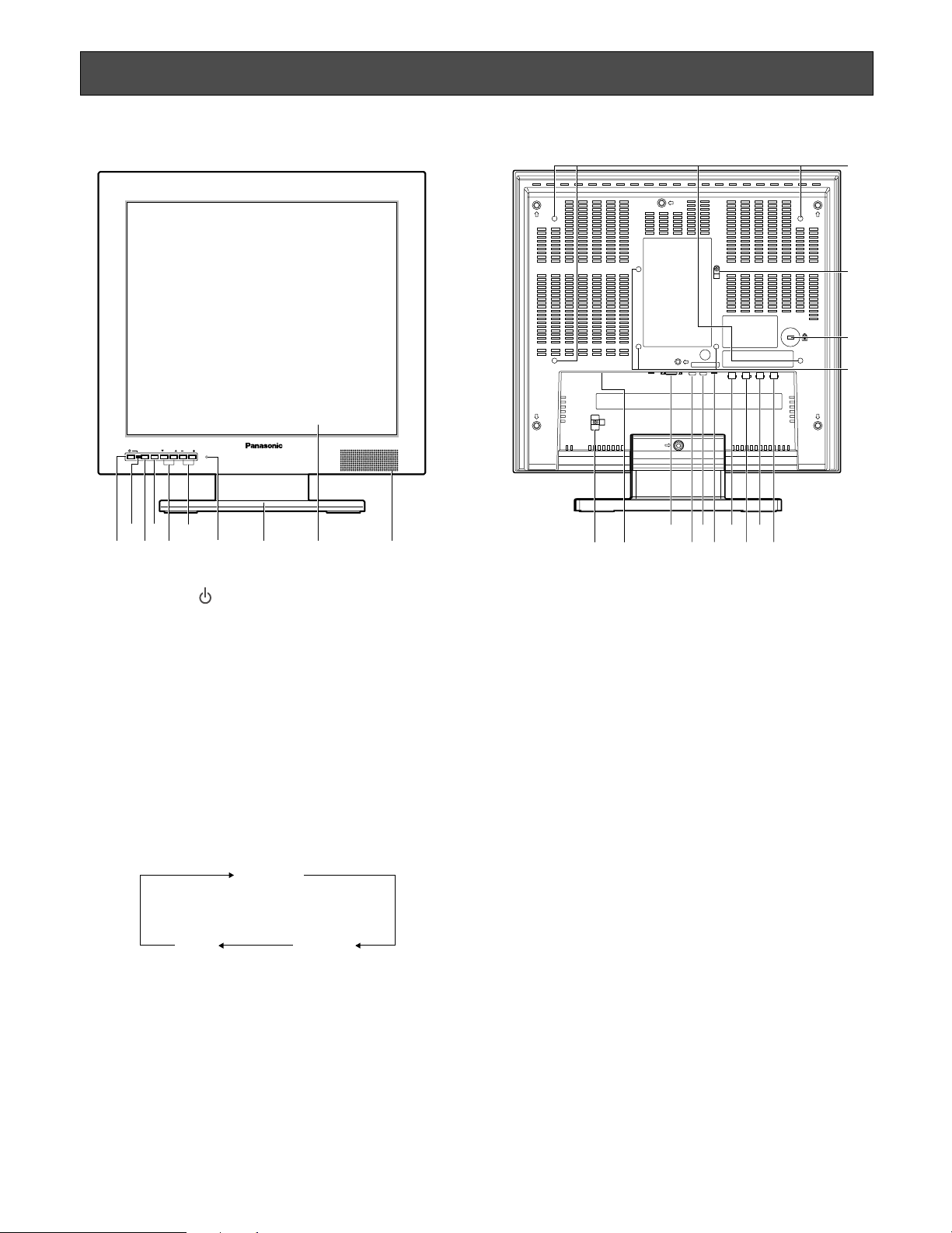
Major Operating Instructions and Their Functions
i
!3
!1 !4!5!6!7!8!9@0
@1
@4
@2
@3
!2
■ Front View
INPUT
MENU SELECT AUDIO
SELECT
r y
w
q
et
u
■ Rear View
Video Monitor WV-LC1900
o !0
q Power button
Powers on or off the monitor.
Note: Power is supplied from the connected cable even
while the monitor is OFF.
w Power indicator
This indicator lights green while power is supplied to
the monitor. Even though the monitor power is turned
off, it lights in red while the power supply is available.
e Input signal selection button (INPUT SELECT)
Every pressing this button can change input signals as
follows.
VIDEO A
PC
r Menu button (MENU)
• Displays the VIDEO ADJUST menu.
• Determines the selected parameter in setup menus.
t Selection buttons (SELECT: C, D)
These buttons move the cursor in setup menus.
y Audio buttons (AUDIO: +, –)
These buttons adjust the audio volume level. These buttons increments or decrements the selected parameter
in setup menus.
8
VIDEO B/
S-VIDEO
u Reset switch
Provideds restart this unit as necessary.
i Monitor stand
o LCD panel
Note: Take care not to pinch your hands or fingers
between the LCD panel and the monitor stand.
!0 Speaker
!1 Power cord clamp
After the power cord has been connected, remove the
screw that is used to mount the power cord clamp and
fasten the power cord.
!2 Power input jack (AC IN)
Connect the power cord (accessory).
!3 PC input connector (PC IN)
Accepts an analog RGB signal from a PC.
Note: For timing data this connector supports, refer to
p. 9 "Timing data chart for PC input".
!4 Audio input connector (AUDIO IN)
With an audio cable connection, this connector accepts
an audio signal from an external device and supplies
the signal to the built-in speaker.
!5 Audio output connector (AUDIO OUT)
Supplies an audio signal accepted by the AUDIO IN
connector to another external device.
Page 9

!6 S-video input connector (S-VIDEO IN)
Accepts an S-video signal from an external device.
Note: This connector and the VIDEO-B IN connector is
connected to the same device. When an S-video
signal and composite video signal are supplied
from a device at the same time, the S-video signal
is accepted by priority.
!7 Video input B connector (VIDEO-B IN)
Accepts a composite video signal from an external
device.
!8 Video output B connector (VIDEO-B OUT)
Supplies a composite video signal accepted by the
VIDEO-B IN connector to another external device.
!9 Video input A connector (VIDEO-A IN)
Accepts a composite video signal from an external
device.
Timing data chart for PC input
This monitor supports the timing data listed as follows.
@0 Video output A connector (VIDEO-A OUT)
Supplies a composite video signal accepted by the
VIDEO-A IN connector to another external device.
@1 Screw holes for rack mount bracket (☞ page 10)
@2 Fall prevention clamp
Using the clamp with strong wire or chain (commercially available), secure the monitor to a sufficiently strong
wall or pillar for fall prevention.
When a wall mounting bracket is used, remove the
clamp.
@3 Security slot
You can attach a lock that meets the industry standard
specification (3 to 3.26 mm x 7 to 7.26 mm x 3.5 to
4 mm) {0.12" x 0.28" x 0.15"}.
@4 Screw holes for wall mount bracket (☞ page 11)
Resolution Vertical
640 x 480
800 x 600
1024 x 768
1280 x 1024
Notes:
• If an input signal does not meet the standards (dot clock frequency, horizontal frequency, and vertical frequency), "OUT
OF RANGE" will appear on the screen.
frequency (Hz)
60
72
60
75
Horizontal
frequency (kHz)
37.985640 x 400
31.5
37.9
64.0
80.0
Dot clock
frequency (MHz)
31.500 VESA standard
35.50037.985720 x 400
25.175
31.500
31.50037.575
36.00035.156
40.00037.960
50.00048.172
49.50046.975
65.00048.460
75.00056.570
78.75060.075
108.00067.5751152 x 864
108.00060.0601280 x 960
108.000
135.000
Standards
VESA standard
Industry standard
VESA standard
VESA standard
VESA guideline
VESA guideline
VESA standard
VESA standard
VESA guideline
VESA standard
VESA standard
VESA standard
VESA standard
VESA standard
VESA standard
• This monitor does not support plug-and-play.
9
Page 10

Installations
WARNING
The installations described in the figures should be made by qualified service personnel or system installers.
Caution: Attach this monitor to a flat wall with a locally procured mounting bracket. After the installation, secure the monitor to
prevent dropping.
Important:
• Do not block the ventilation opening or slots on the cover.
• Do not mount the monitor on places subject to constant vibrations. That may cause trouble or damage.
■ Installation this monitor in a rack
Use the rack mount bracket WQ-LM191 (option) and the rack mounting screws (locally procured) to install this unit in a rack.
z Remove the screw of stand cover (M4), and then
remove the stand cover.
x Remove the four screws of monitor stand, and then
remove the monitor stand.
Stand cover
Screw (M4)
Screw (M4)
Monitor stand
Screw holes for rack mount bracket
Note:
The removed stand cover, monitor stand and screws
should be retained for future use.
c Install the rack mount brackets on the rear of the moni-
tor.
Fix the rack mount brackets firmly using four fixing
screws (provided) (M4).
10
Screws (M4)
Page 11

v Install this unit in the rack.
Fix this unit firmly using eight mounting screws (locally
procured).
b Adjust the angle of this unit.
The angle can be adjusted from 0 ° down to 20 °.
Rack mounting screws
(locally procured)
Important:
During angle adjustments, be careful not to pinch your hand or fingers in the gap. Never press the LCD panel.
Notes on the screw holes for wall mount bracket
• Check how heavy the wall mount bracket and this unit are.
• Examine the strength of the area on the wall where the monitor is to be mounted, and the pull-out strength should be more
than 5 times the total weight of the wall mount bracket and this unit.
11
Page 12

Connections
■ Connection Example
Monitor output
(VGA)
PC
Other video monitors
Audio inputVideo input
12
* Be sure to secure the
power cord with a power
cord clamp.
Power cord
(supplied)
Digital disk recorder
Audio
output
S-video
output
Video
output
Page 13

■ Camera Connection
Connect the video output connector of camera to the
VIDEO IN connector with a coaxial cable.
Note: Make sure that the cable length between the camera
and monitor is as follows.
● To Output Audio Signal
Connect the AUDIO IN connector of this monitor to the
audio output connector of digital disk recorder (or other
recording devices) with an audio cable.
Cable type
RG-59/U 3C-2V
RG-6/U 5C-2V
RG-11/U 7C-2V
RG-11/U 10C-2V
Cable length
250 m {820 ft.}
500 m {1 640 ft.}
600 m {1 968 ft.}
800 m {2 625 ft.}
■ Connection with Two or More
Video Monitors
• Connect the VIDEO OUT connector of this monitor to
the video input connector of another monitor with a
coaxial cable.
• Connect the AUDIO OUT connector of this monitor to
the audio input connector of another monitor with an
audio cable.
Notes:
• Up to 10 monitors can be connected to this monitor. If
11 or more monitors are connected, picture quality may
be degraded.
• Total length of each cable should not exceed 150 m
{492 ft.}.
■ PC Connection
Connect the PC IN connector of this monitor to the analog
RGB output connector of PC (or another device).
Check the room around the PC IN connector at the rear and
procure a suitable 15-pin Mini D-sub connector cable
before the cable connection.
■ Digital Disk Recorder
Connection
● To Perform Recording
• Connect the VIDEO OUT connector of this monitor to
the video input connector of digital disk recorder (or
other recording devices) with a coaxial cable.
• If necessary, connect the AUDIO OUT connector of the
monitor to the audio input connector of digital disk
recorder (or other recording devices) with an audio
cable.
● To Perform Playback
Do either of the following.
• Connect the VIDEO IN connector of this monitor to the
video output connector of digital disk recorder (or other
recording devices) with a coaxial cable.
• Connect the S-VIDEO IN connector of this monitor to
the S-video output connector of digital disk recorder (or
other recording devices) with an S-video cable.
13
Page 14

Power-On
Before operation, check the connections between monitors
and external devices (cameras, digital disk recorders, etc.)
(Refer to p. 12)
1. Press the power button. The monitor will be powered
on, and the power indicator will light up in green.
2. Press the INPUT SELECT button.
Every pressing this button can change input signals as
follows.
VIDEO A
PC
The signal name will be displayed on the upper right
corner of screen for 3 seconds.
Signal name Input signal type
VIDEO A Composite video A
VIDEO B Composite video B
S-VIDEO S-video
PC PC (Analog RGB)
VIDEO B/
S-VIDEO
Notes:
• When no input signal is supplied to the monitor, "NO
SIGNAL" will be displayed on the screen.
"NO SIGNAL" will continue to be displayed until an input
signal is supplied.
• When the loss of input signal is detected due to cable
disconnection, etc., "VIDEO LOSS" will be displayed on
the screen.
"VIDEO LOSS" will continue to be displayed until a
cable is connected.
14
• When the PC input signal is selected and picture display position is not proper, perform the output setting of
the connected PC. (Refer to the diagram in p. 9.)
Page 15

Audio Volume Control
By pressing the + or – button during picture display, you can adjust the audio volume level. While the + or – button is pressed,
the volume level is displayed on the screen.
–: Audio volume level goes down.
+: Audio volume level goes up.
Setting item Effect Setting value
AUDIO +: Audio volume level goes up.
–: Audio volume level goes down.
0 to + 40
AUDIO
22
Video Adjustment and Setup
■ Video Adjustment (Video Input,
S-Video Input)
Setup of this monitor will be performed in the VIDEO
ADJUST menu.
Notes:
• The menu title display differs depending on the selected input signal. Before adjustment, press the INPUT
SELECT button surely to select the input signal. (Refer
to p. 13.)
• If the power is shut down during setup, the setting values will not be saved.
1. Press the MENU button. The top menu will be displayed.
2. Move the cursor to VIDEO ADJUST by pressing the C
or D button. Press the MENU button.
The VIDEO ADJUST menu will be displayed.
Present input signals are displayed in the menu title.
For video input (A): VIDEO A IN
For video input (B): VIDEO B IN
For S-video input: S-VIDEO IN
VIDEO B IN
BRIGHTNESS
CONTRAST
SHARPNESS
COLOR
TINT
H-POINT
COLOR TEMP
SCAN
NORMAL SETTINGS
EXIT
6500K
FULL
NTSC
00
00
00
00
00
00
VIDEO ADJUST
P C S E T U P
LANGUAGE
E X I T
To the right side of the menu title, the input signal type
is displayed as specified below.
NTSC: When a video signal input of the NTSC system is
entered or if there is no signal
PAL: When a video signal input of the PAL system is
entered
15
Page 16

Notes:
• The respective setting items are allowed to set up different values in regard to each input signal. However, the same values are used in common for the video input B and S-video input.
• "TINT" can be adjusted only if the input signal is of the NTSC system.
3 Move the cursor to the following setting items by pressing the C or D button. Then, adjust the levels by pressing the + or –
button.
Setting item
BRIGHTNESS
CONTRAST +: Contrast level goes up.
SHARPNESS +: Picture quality becomes sharper.
COLOR +: Color density level goes up.
TINT (NTSC system only)
H-POSITION
COLOR TEMP
SCAN
Effect Setting value
+: Brightness level goes up.
–: Brightness level goes down.
–: Contrast level goes down.
–: Picture quality becomes softer.
–: Color density level goes down.
+: Tint becomes more greenish.
–: Tint becomes more reddish.
+: Position is moved to the right.
–: Position is moved to the left.
– 20 to + 20
– 20 to + 20
– 7 to + 7
– 20 to + 20
– 20 to + 20
– 10 to + 10
6500K: Reddish color is intensi-
fied (default).
9300K: Blue color is intensified.
FULL:
The overall video image is displayed throughout the screen.
The aspect ratio of the video
image is disregarded and the
displayed image appears
somewhat slender.
OVER:
The screen height and the
image height are joined to display. Since the enlarged
aspect ratio remains to be 1:1,
the right and left parts of the
image are slightly lost.
UNDER:
The screen width and the
image width are joined to display. Since the enlarged
aspect ratio remains to be 1:1,
black strips are displayed in
the top and bottom parts of
the image.
Note: Value can be set differently for each input signal.
4. To reset the settings, move the cursor to NORMAL SETTINGS by pressing the C or D button. Press the MENU button.
The currently displayed input signal (VIDEO A, VIDEO B, or S-VIDEO) will be reset to the factory default.
5. To return to the top menu, move the cursor to EXIT by pressing the C or D button. Then, press the MENU button.
6. After returning to the top menu, move the cursor to EXIT by pressing the C or D button. Then, press the MENU button.
The monitor display return to the default status.
Note: If no operation has been performed for 10 seconds or more, the monitor display returns to the default status.
16
Page 17

■ Video Adjustment (PC Input
Connector)
Adjustment of this monitor will be performed in the VIDEO
ADJUST menu.
Note: The menu title display differs depending on the
selected input signal. Before adjustment, press the
INPUT SELECT button surely to select the input signal.
(☞ Page 8)
VIDEO ADJUST
P C S E T U P
LANGUAGE
E X I T
1. Move the cursor to VIDEO ADJUST by pressing the C
or D button. Press the MENU button. The VIDEO
ADJUST menu will be displayed.
Present input signals are displayed in the menu title.
For PC input: PC IN
PC IN 1280 x 1024@60 Hz
BRIGHTNESS
CONTRAST
COLOR TEMP
USER COLOR-R
USER COLOR-G
USER COLOR-B
NORMAL SETTINGS
EXIT
6500K
00
00
00
00
00
According to the timing data table (☞ Page 9), present
signals are displayed in the following position of the
menu title in the format of [Resolution@Refresh rate
(Vertical frequency)].
3. Move the cursor to the following setting items by pressing the C or D button. Then, adjust the levels by pressing the + or
– button.
Setting item Effect Setting value
BRIGHTNESS
+: Brightness level goes up.
– 20 to + 20
–: Brightness level goes down.
CONTRAST +: Contrast level goes up.
– 20 to + 20
–: Contrast level goes down.
COLOR TEMP 6500K: Red is intensified
(default).
9300K: Blue is intensified.
USER: User colors (R/G/B) are
adjustable.
USER COLOR-R +: Red density level goes up.
– 20 to + 20
–: Red density level goes down.
USER COLOR-G +: Green density level goes up.
– 20 to + 20
–: Green density level goes down.
USER COLOR-B +: Blue density level goes up.
– 20 to + 20
–: Blue density level goes down.
Note: USER COLOR-R, USER COLOR-G, and USER COLOR-B can be adjusted only if USER has been chosen for COLOR
TEMP.
4. To reset the settings, move the cursor to NORMAL SETTINGS by pressing the C or D button. Press the MENU button.
The currently displayed input signal (PC input) will be reset to the factory default.
5. Select EXIT, and press the MENU button. The top menu will be displayed.
6. Select EXIT on the top menu, and press the MENU button. The monitor display return to the default status.
Note: If no operation has been performed for 10 seconds or more, the monitor display returns to the default status.
17
Page 18

■ Setting of PC Input
While the PC input signal is being selected, you can adjust
the horizontal position and vertical position.
Note: Since this unit detects input signals and makes auto-
matic adjustments as required, this setting is not
required in ordinary cases.
1. Press the MENU button. The top menu will be displayed.
VIDEO ADJUST
P C S E T U P
LANGUAGE
E X I T
2. Move the cursor to SETUP by pressing the C or D button. Press the MENU button. The PC SETUP menu will
be displayed.
PC IN 1280 x 1024@60 Hz
H-POSITION
V-POSITION
CLOCK
PHASE
AUTO
EXIT
00
00
+01
+38
According to the timing data table (☞ Page 9), present
signals are displayed at the right side of the menu title
in the format of [Resolution@Refresh rate (Vertical frequency)].
3. Move the cursor to AUTO by pressing the C or D but-
ton. Press the MENU button. The image display position
will be adjusted automatically.
Notes:
• The screen flickers during automatic adjustments. This
is, however, not a malfunction.
• According to the situation of video signals, it takes several seconds to 10-odd seconds to complete automatic
adjustments.
Present input signals are displayed in the menu title.
For PC input terminal: PC IN
If an optimal screen cannot be obtained after automatic
adjustments, further operation specified below may be
needed.
4. Move the cursor to the following setting items by pressing the C or D button. Then, adjust the levels by pressing the + or –
button.
Setting item
H-POSITION
Effect Setting value
+: Screen moves to the right.
– 40 to + 40
–: Screen moves to the left.
V-POSITION
+: Screen moves upwards.
– 20 to + 20
–: Screen moves downwards.
CLOCK
+: Clock is enlarged.
– 20 to + 20
–: Clock is contracted.
PHASE
+: Phase is increased.
0 to +63
–: Phase is decreased.
5. Select EXIT, and press the MENU button. The top menu will be displayed.
6. Select EXIT on the top menu, and press the MENU button. The monitor display return to the default status.
Notes:
• If no operation has been performed for 10 seconds or more, the monitor display returns to the default status.
• Check if the VGA output setting has been performed for the connected PC. (Refer to p. 9.)
• This monitor does not support plug-and-play. Depending on the connected PC, the PC SETUP menu can be controlled
from the PC keyboard. However, proper adjustment is not supported.
18
Page 19

■ Language Setup
You can select the language for monitor display.
Note: If the power is shut down during setup, the setting
values will not be saved.
1. Press the MENU button. The top menu will be displayed.
VIDEO ADJUST
P C S E T U P
LANGUAGE
E X I T
2. Move the cursor to LANGUAGE by pressing the C or
D button. Press the MENU button. The LANGUAGE
menu will be displayed.
LANGUAGE
ENGLISH
FRANÇAIS
DEUTSCH
ESPAÑOL
ITALIANO
EXIT
3. Move the cursor to the desired language by pressing
the C or D button. Press the MENU button. The selected language will be applied for monitor display.
4. Select EXIT, and press the MENU button. The top menu
will be displayed.
Note: When any language other than Japanese is selected,
the menu title and the statement of [Return] will be
turned into notation of the selected language.
5. Select EXIT on the top menu, and press the MENU button. The monitor display return to the default status.
Note: If no operation has been performed for 10 seconds
or more, the monitor display returns to the default status.
19
Page 20

Troubleshooting
Check the following before requesting repair.
If a trouble cannot be corrected even after checking and trying remedy, contact your dealer.
Symptom
Power is not turned on.
"NO SIGNAL" appears on the
screen, and no image is displayed.
"OUT OF RANGE" appears on
the screen, and no picture is displayed.
Picture display position is not
proper while the PC input signal
is being selected.
Cause/solution
Check if the power plug is properly connected to the AC outlet.
Check if the power plug is properly inserted into the DC IN jack
of this monitor.
Check the cables are properly inserted into the connectors. 8 - 9, 13
Check if the cable connection is corresponding with the selected
input signal.
When the PC input signal does not meet the standards of this
monitor, no picture is displayed.
→ Check the specifications of connected PC.
Perform auto adjustment on the PC menu. If the picture display
position is not properly adjusted, perform manual adjustment.
Reference
pages
–
–
8 - 9, 13
9, 18
18
The power cord insulation is
damaged.
The power cord, plug and connectors get hot during use.
The power cord gets hot when
bent or stretched.
"VIDEO LOSS" appears in the
center of the screen, and no
image is displayed.
No reaction is observed by
pressing the front buttons.
The power cord, plug and connectors are worn out.
If you continue to use it, a fire or an electric shock may occur.
Unplug the AC adapter immediately, and refer servicing to qualified service personnel.
Check whether the cable is appropriately connected.
Check whether the external devices such as the camera are
turned on.
Press the reset switch to restart this unit.
–
8 - 9
8 - 9
20
Page 21

Specifications
Power source: 120 V AC, 60 Hz
Power consumption: 41 W (WV-LC1700), 43 W (WV-LC1900)
Display panel: 17" (WV-LC1700), 19" (WV-LC1900) TFT LCD, built-in dual CCFT's
Display area: 337 mm (H) x 270 mm (V) {13-1/4" (H) 10-5/8" (V)} (WV-LC1700)
376 mm (H) x 301 mm (V) {14-13/16" (H) 11-7/8" (V)} (WV-LC1900)
Number of pixels: 1 280 x 1 024 (SXGA)
Aspect ratio: 5 : 4
Maximum brightness: 300 cd/m
Maximum contrast ratio: 800 : 1 (typical)
Display colors: Approx. 16 700 000
Viewing angle (L/R/U/D): 80 °/80 °/75 °/85° (contrast ratio 10 : F1, typical)
TV mode: Composite video input / Y/C video input: NTSC/PAL (auto)
Horizontal resolution: 500 or more TV lines
Video input
(VIDEO-A IN, VIDEO-B IN): 1.0 V [P-P]/75 Ω (BNC), composite video signal
Video output
(VIDEO-A OUT, VIDEO-B OUT): Auto-termination loop-thru (BNC)
S-video input (S-VIDEO IN): Y=1.0 V [P-P]/75 Ω, C= 0.3 V [P-P]/75 Ω, mini DIN jack
PC input (PC IN): RGB, 0.7 V [P-P]/75 Ω, horizontal and vertical timing pulse: TTL, 15-pin mini D-sub
connector
Speaker output: 0.5 W
Audio input: –8 dB/Hi-Z, RCA pin jack
Audio output: Loop-thru output, RCA pin jack
Ambient operating temperature: 0 °C to +40 °C {+32 °F to +104°F}
Ambient storage temperature: –20 °C to 60 °C {–14 °F to +140°F}
Ambient operating humidity: Less than 90 %
Screw holes for VESA mounting bracket: 100 mm {3-15/16"} pitch, VESA standard
Dimensions: WV-LC1700: 404 mm (W) x 415 mm (H) x 236 mm (D)
WV-LC1900: 423 mm (W) x 440 mm (H) x 236 mm (D)
Weight: WV-LC1700: 9.0 kg {20 lbs.} (including the monitor stand)
WV-LC1900: 10 kg {22 lbs.} (including the monitor stand)
2
(typical)
{15-15/16" (W) x 16-3/8" (H) x 9-5/16" (D)}
(including the monitor stand)
404 mm (W) x 365 mm (H) x 77 mm (D)
{15-15/16" (W) 14-3/8" (H) 3-1/16" (D)} (excluding the monitor stand)
{16-11/16" (W) 17-5/16" (H) x 9-1/16" (D)} (including the monitor stand)
423 mm (W) x 390 mm (H) x 80 mm (D)
{16-11/16" (W) 15-3/8" (H) x 3-1/8" (D)} (including the monitor stand)
7.7 kg {17 lbs.} (excluding the monitor stand)
8.7 kg {19 lbs.} (excluding the monitor stand)
21
Page 22

Appearance
WV-LC1700
404 {15-15/16}
365 {14-3/8}
415 {16-5/16}
41
{1-5/8}
28
{1-1/8}
77
{3-1/16}
5°
15°
WV-LC1900
INPUT
MENU SELECT AUDIO
SELECT
INPUT
SELECT
MENU SELECT AUDIO
Video Monitor WV-LD1700
Video Monitor WV-LC1700
265 {10-7/16} 236 {9-5/16}
423 {16-11/16}
390 {15-3/8}
440 {17-5/16}
INPUT
MENU SELECT AUDIO
SELECT
INPUT
SELECT
MENU SELECT AUDIO
Video Monitor WV-LD1700
Video Monitor WV-LC1900
265 {10-7/16}
50
{2}
30
{1-3/16}
80
{3-3/16}
236 {9-5/16}
5°
15°
(Unit: mm/inch)
22
Page 23

Standard Accessories
Operating Instructions (This Document) .......................... 1 pc.
Warranty Card................................................................... 1 pc.
Power Cord ...................................................................... 1 pc.
23
Page 24

Panasonic System Solutions Company,
Unit Company of Panasonic Corporation of North America
www.panasonic.com/business/
For customer support, call 1.800.528.6747
Three Panasonic Way 2H-2, Secaucus, New Jersey 07094
Panasonic Sales Company
Division of Panasonic Puerto Rico Inc.
San Gabriel Industrial Park 65th Infantry Ave. KM. 9.5
Carolina
P.R. 00985(809)750-4300
Panasonic Canada Inc.
5770 Ambler Drive,Mississauga,
Ontario, L4W 2T3 Canada (905)624-5010
http://www.panasonic.ca
© 2008 Matsushita Electric Industrial Co., Ltd. All Rights Reserved. Nt0708-0/1 3TR005612AAA Printed in Taiwan
 Loading...