

Panasonic WV-CZ392E, WV-CZ492E Operating Instructions Manual
Operating Instructions
Color CCTV Camera
Model No. WV-CZ392E
WV-CZ492E
Before attempting to connect or operate this product,
please read these instructions carefully and save this manual for future use.
The model number is abbreviated in some descriptions in this manual.
This illustration represents WV-CZ392E.
2
Wij verklaren als enige aansprakelijke, dat het
product waarop deze verklaring betrekking heeft,
vold o e t aa n de vol g e nde normen of andere
nor mati e ve docu mente n, overeenk omsti g de
bepa l i n g e n van Ri chtli j n e n 2 0 0 6 / 9 5/EC en
2004/108/EC.
Vi erklærer os eneansvarlige for, at dette produkt,
s o m d e nn e de k la r at i o n o mh a nd l er, e r i
overensstemmelse med standarder eller andre
normative dokumenter i følge bestemmelserne i
direktivene 2006/95/EC og 2004/108/EC.
Vi deklarerar härmed vårt fulla ansvar för att den
produkt till vilken denna deklaration hänvisar är i
överensstämmelse med de standarder eller andra
normativa dokument som framställs i direktiv nr
2006/95/EC och 2004/108/EC.
Ilmoitamme yksinomaisella vastuullamme, että
tuo t e, jota täm ä ilmoit u s koskee , no udatt aa
seuraav i a standardeja tai mu i ta oh j eellisia
asiakirjoja, jotka noudattavat direktiivien 2006/95/
EC ja 2004/108/EC säädöksiä.
Vi erklærer oss alene ansvarlige for at produktet
s o m d e n n e er k l æri n gen g je lde r for, e r i
overensstemmelse med følgende normer eller andre
n o r m g i v e n d e d o k u m e n t e r s o m f ø l g e r
bes temm e lsen e i di rek t iven e 2006/ 9 5/EC og
2004/108/EC.
We declare under our sole responsibility that the
product to which this declaration relates is in
conformity with the standards or other normative
documents following the provisions of Directives
2006/95/EC and 2004/108/EC.
CAUTION: TO REDUCE THE RISK OF ELECTRIC SHOCK,
DO NOT REMOVE COVER (OR BACK).
NO USER-SERVICEABLE PARTS INSIDE. REFER
SERVICING TO QUALIFIED SERVICE PERSONNEL.
CAUTION
RISK OF ELECTRIC
SHOCK DO NOT OPEN
The lightning flash with arrowhead
symbol, within an equilateral
triangle, is intended to alert the
user to the presence of uninsulated
dangerous voltage within the
products enclosure that may be of
sufficient magnitude to constitute a
risk of electric shock to persons.
The exclamation point within an
equilateral triangle is intended
to alert the user to the presence
of important operating and
maintenance (servicing)
instructions in the literature
accompanying the appliance.
Note:
• The serial number of this product may be
found on the rear of the unit. You should
note the serial number of this unit in the
space provided and retain this book as a
permanent record of your purchase to aid
identification in the event of theft.

3
Contents
Important safety instructions ............................................................................................................ 4
Limitation of liability .......................................................................................................................... 5
Disclaimer of warranty ...................................................................................................................... 5
Preface ............................................................................................................................................. 6
About notations ................................................................................................................................ 6
Features ............................................................................................................................................ 6
About the user manuals ................................................................................................................... 6
Precautions ....................................................................................................................................... 7
Precautions for installation ............................................................................................................... 9
Major operating controls .................................................................................................................. 11
Installation and connection .............................................................................................................. 12
Basic operation ................................................................................................................................ 17
Setup menu ...................................................................................................................................... 18
Advanced operation ......................................................................................................................... 21
Quick setup menu ...................................................................................................................... 21
Advanced setup menu ............................................................................................................... 21
Camera setting ........................................................................................................................... 21
Preset position setting ................................................................................................................ 29
Special setting ............................................................................................................................ 32
Communication setting ............................................................................................................... 33
Using the scene select setting menu
.......................................................................................... 34
Language setting ....................................................................................................................... 35
Quick setup ................................................................................................................................ 35
Password lock setting ................................................................................................................ 35
Troubleshooting ................................................................................................................................ 37
Specifications ................................................................................................................................... 38
Standard accessories ...................................................................................................................... 39

4
1) Read these instructions.
2) Keep these instructions.
3) Heed all warnings.
4) Follow all instructions.
5) Do not use this apparatus near water.
6) Clean only with dry cloth.
7) Do not block any ventilation openings. Install in accordance with the manufacturer's
instructions.
8) Do not install near any heat sources such as radiators, heat registers, stoves, or other
apparatus (including amplifiers) that produce heat.
9) Do not defeat the safety purpose of the polarized or grounding-type plug. A polarized
plug has two blades with one wider than the other. A grounding type plug has two
blades and a third grounding prong. The wide blade or the third prong are provided for
your safety. If the provided plug does not fit into your outlet, consult an electrician for
replacement of the obsolete outlet.
10) Protect the power cord from being walked on or pinched particularly at plugs,
convenience receptacles, and the point where they exit from the apparatus.
11) Only use attachments/accessories specified by the manufacturer.
12) Use only with the cart, stand, tripod, bracket, or table specified by the manufacturer,
or sold with the apparatus. When a cart is used, use caution when moving the cart/
apparatus combination to avoid injury from tip-over.
13) Unplug this apparatus during lightning storms or when unused for long periods of time.
14)
Refer all servicing to qualified service personnel. Servicing is required when the
apparatus has been damaged in any way, such as power-supply cord or plug is
damaged, liquid has been spilled or objects have fallen into the apparatus, the apparatus
has been exposed to rain or moisture, does not operate normally, or has been dropped.
Important safety instructions
S3125A

5
Limitation of liability
Disclaimer of warranty
THIS PUBLICATION IS PROVIDED "AS IS" WITHOUT WARRANTY OF ANY KIND, EITHER
EXPRESS OR IMPLIED, INCLUDING BUT NOT LIMITED TO, THE IMPLIED WARRANTIES OF
MERCHANTABILITY, FITNESS FOR ANY PARTICULAR PURPOSE, OR NON-INFRINGEMENT
OF THE THIRD PARTY'S RIGHT.
THIS PUBLICATION COULD INCLUDE TECHNICAL INACCURACIES OR TYPOGRAPHICAL
ERRORS. CHANGES ARE ADDED TO THE INFORMATION HEREIN, AT ANY TIME, FOR THE
IMPROVEMENTS OF THIS PUBLICATION AND/OR THE CORRESPONDING PRODUCT (S).
IN NO EVENT SHALL Panasonic System Networks Co., Ltd. BE LIABLE TO ANY PARTY OR
ANY PERSON, EXCEPT FOR REPLACEMENT OR REASONABLE MAINTENANCE OF THE
PRODUCT, FOR THE CASES, INCLUDING BUT NOT LIMITED TO BELOW:
(1) ANY DAMAGE AND LOSS, INCLUDING WITHOUT LIMITATION, DIRECT OR INDIRECT,
SPECIAL, CONSEQUENTIAL OR EXEMPLARY, ARISING OUT OF OR RELATING TO
THE PRODUCT;
(2) PERSONAL INJURY OR ANY DAMAGE CAUSED BY INAPPROPRIATE USE OR
NEGLIGENT OPERATION OF THE USER;
(3) UNAUTHORIZED DISASSEMBLE, REPAIR OR MODIFICATION OF THE PRODUCT BY
THE USER;
(4) INCONVENIENCE OR ANY LOSS ARISING WHEN IMAGES ARE NOT DISPLAYED,
DUE TO ANY REASON OR CAUSE INCLUDING ANY FAILURE OR PROBLEM OF THE
PRODUCT;
(5) ANY PROBLEM, CONSEQUENTIAL INCONVENIENCE, OR LOSS OR DAMAGE,
ARISING OUT OF THE SYSTEM COMBINED BY THE DEVICES OF THIRD PARTY;
(6) ANY C L A I M OR ACTION F OR DAM A G E S, BRO U G H T BY ANY P E R S ON OR
ORGANIZATION BEING A PHOTOGENIC SUBJECT, DUE TO VIOLATION OF PRIVACY
WITH THE RESULT OF THAT SURVEILLANCE-CAMERA'S PICTURE, INCLUDING SAVED
DATA, FOR SOME REASON, BECOMES PUBLIC OR IS USED FOR ANY PURPOSE.

6
This product is a 1/4 type CCD color CCTV camera. Connection of this product to a video
monitor allows users to use this product as a monitoring camera.
•
WV-CZ392: 36x zoom
•
WV-CZ492: 36x zoom, Super Dynamic 6
The following notations are used when describing the functions limited for specified models.
The functions without the notations are supported by all models.
CZ392
The functions with this notation are available when using the model WV-CZ392.
CZ492
The functions with this notation are available when using the model WV-CZ492.
Preface
About notations
Features
About the user manuals
•
High quality picture of 976 x 582 pixels
•
Minimum illumination of 0.5 lx for color mode
•
Minimum illumination of 0.04 lx for black-and-white mode
•
Privacy zone feature enables users to veil unwanted zones
•
Protocol adaptability to Panasonic's protocol
•
Auto Day/Night mode enables the camera to switch between color and black-and-white
in response to input lights
•
Built-in digital motion detector and alarm outputs
•
Super Dynamic 6 can capture clear images of subjects whose illumination is extremely
different
CZ492
•
Up to 256 preset position
•
Sync is available from internal
•
Automatic gain control circuit
•
Image hold
•
Digital noise reduction effect
•
Setting change executable only by authorized personnel thanks to the password lock
function
•
Enhanced horizontal resolution by resolution setting
The illustrations and screens used in these operating instructions show the case of WV-CZ392.

7
Precautions
The following points as well as the contents of
"Warning" and "Caution" shall be observed.
Refer installation work to the dealer.
Installation work requires technique and
experiences. Otherwise injury, or damage to
this product may result.
Be sure to consult the dealer.
Do not insert any foreign objects.
This could permanetly damage this product.
Turn the power off immediately and contact
qualified service personnel for service.
Do not attempt to disassemble or modify
this product.
Failure to observe this may cause fire or
electric shock.
Consult the dealer for the repair or inspections.
Stop operation immediately when
something is wrong with this product.
When smoke goes up from this product or
the smell of smoke comes from this product,
continued use will result in fire, injury, or
damage to the product.
Turn the power off immediately and contact
qualified service personnel for service.
Select an installation area that can
support the total weight.
Selecti n g an inappro p r iate i n stallation
surface may cause the product to fall down
or topple over, resulting in injury.
Insta l lation work shall be started after
sufficient reinforcement.
Periodic inspections shall be conducted.
Rust on the metal parts or screws may cause
the product to fall down resulting in injury or
accidents.
Consult the dealer for the inspections.
This product shall be installed in a
vibration-free place.
Failure to observe this may cause screws
and bolts to be loosened and consequently
to fall resulting in injury.
Install this product high enough to ensure
that people don't hit their heads.
Failure to observe this may cause a drop
resulting in injury or accidents.
Do not strike or give a strong shock to
this product.
Failure to observe this may cause injury or fire.
Turn the power off when do wiring of this
product.
Failure to observe this may cause electric
shock. A short circuit or wrong wiring may
cause fire.
Do not use this product in an atmosphere
of ammable gases.
Failure to observe this may cause injury by
explosion.
Avoid installing this product in locations
where it is subject to damage by salt or
corrosive gas.
Ot he r w i s e th e mo u n t i ng fi x t u re s wi l l
deteriorate, causing the product to fall down
and leading to accidents.
Tighten screws and mounting xtures to
the specied torque.
Failure to observe this may cause a drop
resulting in injury or accidents.
8
[Precautions for use]
This product is designed to be used
indoors.
This product is not operable outdoors.
This product has no power switch.
When turning off the power, turn off a circuit
breaker.
To keep on using with stable performance
Parts of this product may deteriorate and it
may shorten the lifetime of this product when
using in locations subject to high temperatures
and high humidity. (Recommended operating
temperature: +35 °C {95 °F} or lower)
Do not expose this product to direct heat
sources such as a heater.
Handle this product with care.
Do not drop this product, nor apply shock or
vibration to this product.
Failure to observe this may cause trouble.
Discoloration on the CCD color lter
When continuously shooting a bright light
source such as a spotlight, the color filter
of the CCD may have deteriorated and
it may cause dis coloration. Even when
changing the fixed shooting direction after
continuously shooting a spot light for a
certain period, the discoloration may remain.
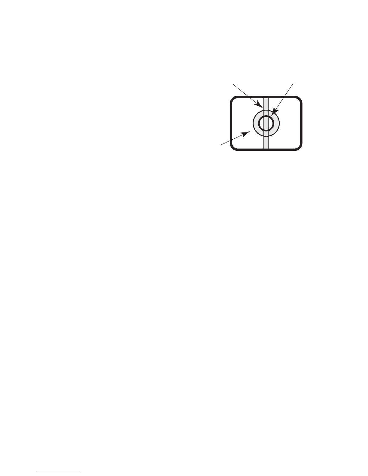
Do not aim this product at strong light
sources.
A light source such as a spot light causes a
blooming (light bleeding) or a smear (vertical
lines).
Cleaning this product body
Turn the power off when c l e a ning t h i s
pro d uc t . Do not us e s tro n g ab ra s ive
deter gent when cleaning this produ ct.
Otherwise, it may cause discoloration.
Synchronous mode setting
Image synchronous mode of this camera
indicates internal synchronization (INT) only.
Set the multiplex vertical driver (VD2) as OFF
when the camera is connected to the system
controller of the company.
Blooming
Smear Bright subject

9
Precautions for installation
Avoid installing this product in the following locations.
•
Location where it may get wet from rain or
water splash.
•
Locations where a chemical agent is
used such as a swimming pool.
•
Locations subject to steam and oil
smoke such as a kitchen, Locations near
flammable gas or vapor.
•
Locations where radiation or x-ray
emissions are produced.
•
Locations where corrosive gas is
produced, Locations where it may be
damaged by briny air such as seashores.
•
Locations where the temperature is not
within –10 °C to +50 °C.
•
Locations subject to vibrations (This
product is not designed for on-vehicle
use.)
Avoid moist or dusty places to install this
system.
Otherwise, lifetime of the internal parts may
be shortened.
Avoid installing this product in a place
with a high level of noise.
Installation near an air conditioner, an air
cleaner, a vending machine, or the like
causes noise.
Be sure to remove this product if it is not
in use.
Keep the camera cable away from the
lighting cable.
Failure to observe this may cause noise.
The following points as well as the
contents of "Warning" and "Caution"
shall be observed.
Panasonic assumes no responsibility
for injuries or property damage resulting
from failures arising out of improper
installation or operation inconsistent with
this documentation.
Installation work shall be performed in
accordance with the technology standard
of the electric installation.
This product is designed to be used
indoors.
This product is not operable outdoors.
Do not expose the product to direct sunlight
for hours and do not install the product near
a heater or an air conditioner. Otherwise, it
may cause deformation, discoloration and
malfunction. Keep the product away from
water and moisture.
Installing place
Contact your dealer for assistance if you
are unsure of an appropriate place in your
particular environment.
•
Make sure that the installation area is
strong enough to hold the product, such
as a concrete ceiling.
•
Install the camera in the foundation area
of the architecture or where sufficient
strength is assured.
•
If a ceiling board such as plaster board is
too weak to support the total weight, the
area shall be sufficiently reinforced.

10
Radio interference
When the camera is used near TV/radio
antenna, strong electric field or magnetic
field (near a motor or a transformer), images
may be distorted and noise sound may be
produced. In such a case, run the camera
cable through specialized steel conduit
tubes.
Locally procure the screws
Screws are not supplied with this product.
Prep a re the sc rew s a c cord i ng to t he
material, structure, strength and other factors
of the mounting area and the total weight of
objects to be mounted.
Screw tightening
•
The screws and bolts must be tightened
with an appropriate tightening torque
according to the material and strength of
the installation area.
•
Do not use an impact driver. Failure to
observe this may cause overtightening
and consequently damage to the screws.
•
When a screw is tightened, make the
screw at a right angle to the surface. After
tightening the screws or bolts, perform
visual check to ensure tightening is
enough and there is no backlash.
11
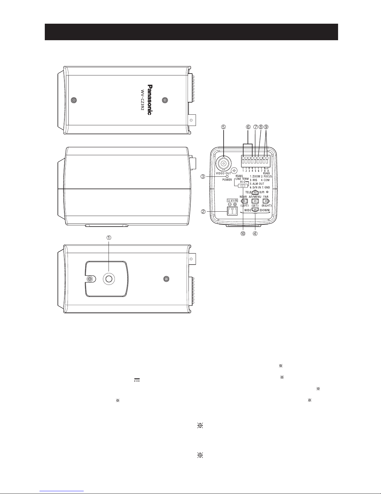
Major operating controls
1
Tripod mount base
2
DC power terminal [12V
IN]
3
Power indicator [POWER
]
4
Operation buttons
1
5
Video output connector
6
Lens control terminal
2
7
Alarm output terminal
2
8
Day/Night input terminal [D/N IN]
2
9
RS485 data In/Output terminal
2
!
RS485 terminal select switch
1:
Zoom, Focus and Auto Focus can
be controlled by setting button if the
setup menu is not opened.
2:
For more information about 6 ~ 9,
refer to page 14.
12
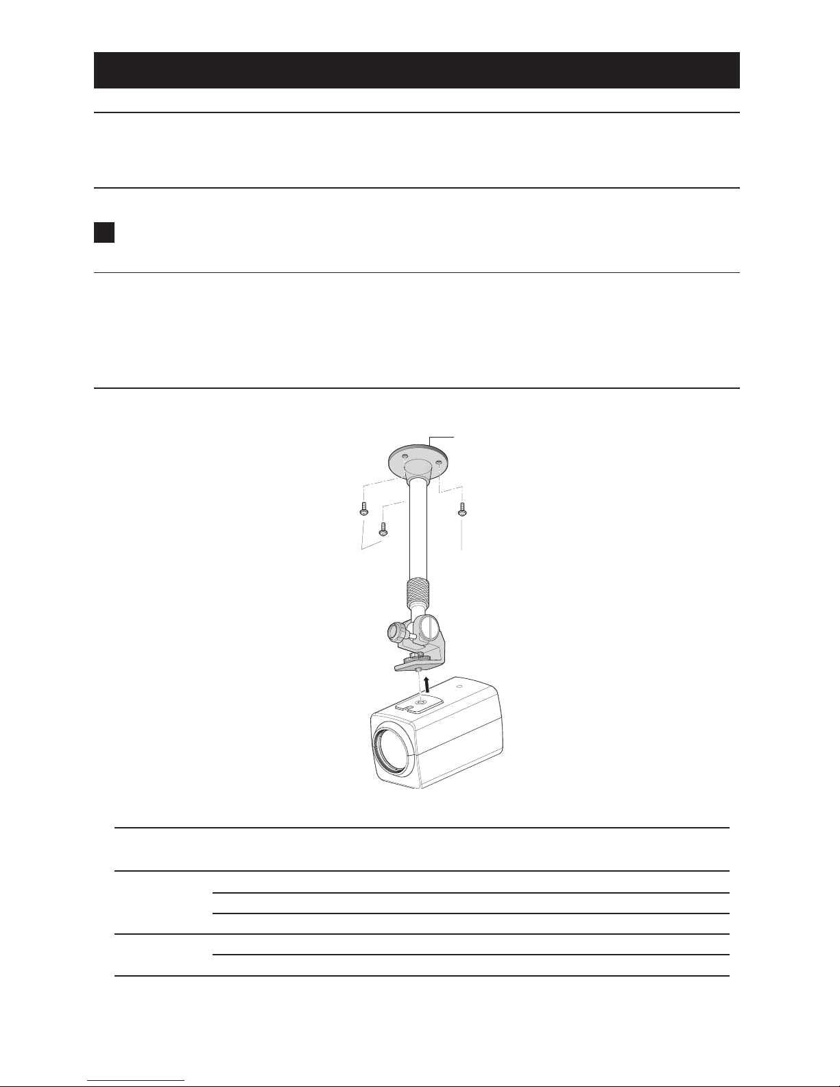
Installation and connection
Important:
•
The following installing and connections should be made by qualified service personnel or
system installers in accordance with all local codes.
1
Secure the camera mount bracket (option) to an installation position, and mount the
camera on the camera mount bracket.
Important:
•
The camera mount bracket shall be mounted on the foundation part of the construction or
a part with adequate strength.
•
When installing on the ceiling, select "ON" for "UPSIDE-DOWN" setting on the setup menu
(refer to page 29).
<Installation sample on a ceiling>
•
The mounting conditions of the camera mount bracket are described as follows:
Installation
place
Applicable
mount bracket
Recommended
screw
Number of
screw
Minimum pull-out
strength (per 1 pc.)
On ceiling WV-7011 M6 4 pcs. 196 N
WV-7010 M8 3 pcs. 196 N
WV-7012 M6 3 pcs. 196 N
On wall WV-831 M8 4 pcs. 921 N
WV-7013 M6 3 pcs. 2.25 kN
For some applicable mount brackets, "A" is attached to the model number. The mounting
conditions are the same even for the A-attached models.
Camera mount
bracket (option)
Screws
(locally procured)
Screws
(locally procured)
 Loading...