

Panasonic WV-CM2080 User Manual
Before attempting to connect or operate this product,
please read these instructions carefully and save this manual for future use.
ENGLISH
DEUTSCHFRANÇAISESPAÑOL
Model No. WV-CM2080
WV-CM1780
WV-CM1480
Colour Monitor
Operating Instructions
POWER
Video
Monitor
WV-CM
2080
O
N
O
F
F
AUDIO
MENU
STANDBY
INPUT
SELECT

2
The lightning flash with arrowhead symbol, within an equilateral triangle, is
intended to alert the user to the presence
of uninsulated "dangerous voltage" within
the product's enclosure that may be of
sufficient magnitude to constitute a risk of
electric shock to persons.
The exclamation point within an equilateral triangle is intended to alert the user
to the presence of important operating
and maintenance (servicing) instructions
in the literature accompanying the appliance.
WARNING:
To reduce the risk of fire or electric shock, do not expose this appliance to rain or moisture.
CAUTION: TO REDUCE THE RISK OF ELECTRIC SHOCK,
DO NOT REMOVE COVER (OR BACK).
NO USER-SERVICEABLE PARTS INSIDE.
REFER SERVICING TO QUALIFIED SERVICE PERSONNEL.
CAUTION
RISK OF ELECTRIC SHOCK
DO NOT OPEN
FOR YOUR SAFETY PLEASE READ THE FOLLOWING TEXT CAREFULLY.
This appliance is supplied with a moulded three pin mains plug for your
safety and convenience.
A 10 amp fuse is fitted in this plug.
Should the fuse need to be replaced please ensure that the replacement
fuse has a rating of 10 amp and that it is approved by ASTA or BSI to
BS1362.
Check for the ASTA mark
H or the BSI mark G on the body of the
fuse.
If the plug contains a removable fuse cover you must ensure that it is
refitted when the fuse is replaced.
If you lose the fuse cover the plug must not be used until a replacement
cover is obtained.
A replacement fuse cover can be purchased from your local Panasonic
Dealer.
IF THE FITTED MOULDED PLUG IS UNSUITABLE FOR THE SOCKET OUTLET IN YOUR HOME THEN THE FUSE SHOULD BE
REMOVED AND THE PLUG CUT OFF AND DISPOSED OF SAFELY.
THERE IS A DANGER OF SEVERE ELECTRICAL SHOCK IF THE
CUT OFF PLUG IS INSERTED INTO ANY 13 AMP SOCKET.
If a new plug is to be fitted please observe the wiring code as shown
below.
If in any doubt please consult a qualified electrician.
WARNING: This apparatus must be earthed.
IMPORTANT
The wires in this mains lead are coloured in accordance with the following code.
Green-and-yellow: Earth
Blue: Neutral
Brown: Live
As the colours of the wire in the mains lead of this appliance may not
correspond with the coloured markings identifying the terminals in your
plug, proceed as follows.
The wire which is coloured green-and-yellow must be connected to
the terminal in the plug which is marked with the letter E or by the earth
symbol
I or coloured green or green-and-yellow.
The wire which is coloured blue must be connected to the terminal in
the plug which is marked with the letter N or coloured black.
The wire which is coloured brown
must be connected to the terminal in
the plug which is marked with the letter L or coloured red.
How to replace the fuse
Open the fuse compartment with
a screwdriver and replace the fuse
and fuse cover.
For U.K.
The serial number of this product may be found on the
rear of the unit.
You should note the serial number of this unit in the
space provided and retain this book as a permanent
record of your purchase to aid identification in the event
of theft.
Model No.
Serial No.
Wij verklaren als enige aansprakelijke, dat het product waarop deze
verklaring betrekking heeft, voldoet aan de volgende normen of
andere normatieve documenten, overeenkomstig de bepalingen
van Richtlijnen 73/23/EEC en 89/336/EEC.
Vi erklærer os eneansvarlige for, at dette produkt, som denne
deklaration omhandler, er i overensstemmelse med standarder eller
andre normative dokumenter i følge bestemmelserne i direktivene
73/23/EEC og 89/336/EEC.
Vi deklarerar härmed värt fulla ansvar för att den produkt till vilken
denna deklaration hänvisar är i överensstämmelse med standarddokument, eller andra normativa dokument som framställs i EECdirektiv nr. 73/23 och 89/336.
Ilmoitamme yksinomaisella vastuullamme, että tuote, jota tämä
ilmoitus koskee, noudattaa seuraavia standardeja tai muita ohjeellisia asiakirjoja, jotka noudattavat direktiivien 73/23/EEC ja 89/
336/EE. säädöksiä.
Vi erklærer oss alene ansvarlige for at produktet som denne
erklæringen gjelder for, er i overensstemmelse med følgende
normer eller andre normgivende dokumenter som følger bestemmelsene i direktivene 73/23/EEC og 89/336/EEC.
We declare under our sole responsibility that the product to which
this declaration relates is in conformity with the standards or other
normative documents following the provisions of Directives EEC/
73/23 and EEC/89/336.
Noi dichiariamo sotto nostra esclusiva responsabilità che il prodotto
a cui si riferisce la presente dichiarazione risulta conforme ai
seguenti standard o altri documenti normativi conformi alle disposizioni delle direttive CEE/73/23 e CEE/89/336.

3
CONTENTS
PREFACE .................................................................................................................................................... 4
FEATURES .................................................................................................................................................. 4
PRECAUTIONS ........................................................................................................................................... 4
MAJOR OPERATING CONTROLS AND THEIR FUNCTIONS .................................................................... 5
INSTALLATION ........................................................................................................................................... 7
CONNECTIONS .......................................................................................................................................... 8
SETUP PROCEDURES ............................................................................................................................... 10
OPERATING PROCEDURES ...................................................................................................................... 12
OPERATING PROCEDURES (with the System Controller) ......................................................................... 15
APPENDIX .................................................................................................................................................. 16
SPECIFICATIONS ....................................................................................................................................... 18
ACCESSORIES ........................................................................................................................................... 19
ENGLISH VERSION
ENGLISH
The model numbers listed in this Operating Instructions have no suffixed attached to it.

4
The Panasonic WV-CM2080, WV-CM1780 and WV-CM1480
Colour Monitor’s high resolution S-video input assures high
definition picture quality.
All monitor functions, except for power and input selection,
can be controlled from an onscreen menu. Provided with
power saving feature as well as standard BNC and S-video
input connectors for connection to CCTV equipment.
PREF ACE
• Refer all work related to the installation of this product to qualified service personnel or system
installers.
• Do not block the ventilation opening or slots on the
cover.
To prevent the appliance from overheating, place it at
least 5 cm (2 inches) away from the wall.
• Do not drop metallic parts through slots.
This could permanently damage the appliance. Turn
the power off immediately and contact qualified service
personnel for service.
• Do not attempt to disassemble the appliance.
To prevent electric shock, do not remove screws or
covers.
There are no user-serviceable parts inside. Contact
qualified service personnel for maintenance.
• Handle the appliance with care.
Do not strike or shake it, as this may damage the appliance.
• Do not expose the appliance to water or moisture,
nor try to operate it in wet areas.
Take immediate action if the appliance becomes wet.
Turn the power off and refer servicing to qualified service personnel. Moisture may damage the appliance
and also cause electric shock.
• Do not use strong or abrasive detergents when
cleaning the appliance body.
Use a dry cloth to clean the appliance when it is dirty.
When the dirt is hard to remove, use a mild detergent
and wipe gently. Afterwards, wipe off the remained part
of the detergent in it with a dry cloth.
• Do not operate the appliance beyond its specified
temperature, humidity or power source ratings.
Use the appliance at temperatures within –10°C +50°C (14°F - 122°F) and a humidity below 90 %.
The input power source for this appliance is 220 V 240 V AC 50 Hz.
PRECAUTIONS
FEATURES
• Approx. 508 mm (20-inch) viewable area with a horizontal resolution of 500 TV lines (WV-CM2080)
• Approx. 406 mm (16-inch) viewable area with a horizontal resolution of 800 TV lines (WV-CM1780)
• Approx. 356 mm (14-inch) viewable area with a horizontal resolution of 750 TV lines (WV-CM1480)
• Three selectable inputs, including two composite and
one S-video input
• Two standby modes for power saving: lower display
brightness and blackout
• Maximum speaker output of 0.7 W
• The monitor can be controlled with the specified system controller using PS•Data (Panasonic Security Data)
mode.
• Onscreen Setup menu
• Supplied with rack mounting brackets for mounting in a
rack (WV-CM2080)
The WV-CM2080, WV-CM1780 or WV-CM1480, and other
devices compatible with Panasonic Security Data mode the
bear logo
.
5
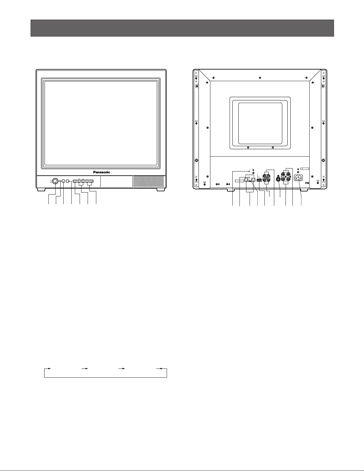
MAJOR OPERATING CONTROLS AND THEIR FUNCTIONS
ON
OFF
POWER
STANDBY
INPUT
SELECT
MENU
–+
AUDIO
Video Monitor WV-CM
2080
q w e
t
y
u
r
* The above figures represent model WV-CM2080.
q Power Button (POWER ON/OFF)
This button turns the power of the monitor on and off.
w Power Indicator
Is on when the power of the monitor is turned on, also
in standby mode.
On: Green light
Standby: Orange light
e Standby Button (STANDBY)
Pressing this button toggles the display mode on the
monitor screen as shown below.
On: Normal display
Standby (Mode 1): Low display brightness
Standby (Mode 2): No display (blackout)
r Input Selection Button (INPUT SELECT)
Selects input in the sequence shown below.
t Menu Button (MENU)
Pressing this button opens the Display Setting menu for
changing the monitor’s display settings.
Pressing this button for 5 seconds or more opens the
COMMUNICATION SETUP menu.
● Front View
AUDIO
VIDEO
OUTIN OUT
AINB
IN
AINB
IN
OUT OUT
AC IN
S-VIDEO
G
STANDBY
ON
STANDBY
OFF
ON OFF
TERMINATION
FOCUS
DATA
PS·Data
!6
@1
!8
!5
!7
!4!3
!1
!2
!9@0
● Rear View
y Direction Button (C, D)
These buttons move the cursor to the item parameters
in the Display Setting and Setup menus.
C: Down
D: Up
u Decrement/Increment Button (AUDIO -, +)
Press these buttons to increase or decrease the audio
volume.
These buttons also select the item parameter or level in
the Display Setting and Setup menu.
!1 Focus Control (FOCUS)
This control adjusts the screen focus.
!2 Screen Control
This control is preset at the factory.
!3 Data Ports (DATA)
These ports are used to exchange control data with the
System Controller in Panasonic Security Data mode.
!4 Data Termination Selector (TERMINATION ON/OFF)
This selector is used to enable termination of the monitor’s data port.
VIDEO IN A VIDEO IN B S-VIDEO IN

6
!5 Standby Control Terminal (STANDBY ON/STANDBY
OFF/G)
This terminal accepts input from an outboard device to
control the standby mode.
It operates as follows:
STANDBY ON: Establishes the specified standby
mode.
STANDBY OFF: Releases standby mode (normal dis-
play).
!6 Audio Input Connectors (AUDIO IN A/B)
For audio input from an outboard device
!7 Audio Output Connectors (AUDIO OUT A/B)
The audio input signal connected to the Audio Input
Connector is looped through to this connector.
!8 S-Video Input Connector (S-VIDEO IN)
For input of S-video signal from an outboard device.
!9 Video Input Connectors (VIDEO IN A/B)
For input of composite video signal from an outboard
device.
@0 Video Output Connectors (VIDEO OUT A/B)
The video input signal connected to the Video Input
Connector is looped through to this connector and terminated automatically.
@1 AC Inlet Socket (AC IN)
Plug the power cord (supplied as a standard accessory) into this socket and connect it to an AC outlet.
 Loading...