

Page 1
Colour Monitor
WV-CM2000
Before attempting to connect or operate this product, please read these instructions completely
DEUTSCHFRANÇAIS ENGLISH
D
Page 2
The serial number of this product may be found on the
bottom of the unit.
You should note the serial number of this unit in the
space provided and retain this book as a permanent
record of your purchase to aid identification in the event
of theft.
Model No.
Serial No.
THIS APPARATUS MUST BE EARTHED.
To ensure safe operation the three-pin plug supplied must be inserted only into a standard three-pin power point which is effectively
earthed through the normal household wiring. Extension cords used
with the equipment must be three-core and be correctly wired to provide connection to earth. Wrongly wired extension cords are a major
cause of fatalities.
The fact that the equipment operates satisfactorily does not imply
that the power point is earthed and that the installation is completely
safe. For your safety, if in any doubt about the effective earthing of
the power point, consult a qualified electrician.
The lightning flash with arrowhead symbol, within an equilateral triangle, is
interned to alert the user to the presence
of uninsulated "dangerous voltage" within
the product's enclosure that may be of
sufficient magnitude to constitute a risk of
electric shock to persons.
The exclamation point within an equilateral triangle is intended to alert the user
to the presence of important operating
and maintenance (servicing) instructions
in the literature accompanying the appliance.
WARNING:
TO PREVENT FIRE OR SHOCK HAZARD, DO NOT EXPOSE THIS APPLIANCE TO RAIN OR MOISTURE.
CAUTION:
TO REDUCE THE RISK OF ELECTRIC SHOCK,
DO NOT REMOVE COVER (OR BACK), NO USER
SERVICEABLE PARTS INSIDE.
REFER SERVICING TO QUALIFIED SERVICE
PERSONNEL.
CAUTION
RISK OF ELECTRIC SHOCK
DO NOT OPEN
For Australia
FOR YOUR SAFETY PLEASE READ THE FOLLOWING TEXT CAREFULLY.
This appliance is supplied with a moulded three pin mains plug for your
safety and convenience.
A 13 amp fuse is fitted in this plug.
Should the fuse need to be replaced please ensure that the replacement
fuse has a rating of 13 amp and that it is approved by ASTA or BSI to
BS1362.
Check for the ASTA mark
H or the BSI mark G on the body of the
fuse.
If the plug contains a removable fuse cover you must ensure that it is
refitted when the fuse is replaced.
If you lose the fuse cover the plug must not be used until a replacement
cover is obtained.
A replacement fuse cover can be purchased from your local Panasonic
Dealer.
IF THE FITTED MOULDED PLUG IS UNSUITABLE FOR THE SOCKET OUTLET IN YOUR HOME THEN THE FUSE SHOULD BE
REMOVED AND THE PLUG CUT OFF AND DISPOSED OF SAFELY.
THERE IS A DANGER OF SEVERE ELECTRICAL SHOCK IF THE
CUT OFF PLUG IS INSERTED INTO ANY 13 AMP SOCKET.
If a new plug is to be fitted please observe the wiring code as shown
below.
If in any doubt please consult a qualified electrician.
WARNING: This apparatus must be earthed.
IMPORTANT
The wires in this mains lead are coloured in accordance with the following code.
Green-and-yellow: Earth
Blue: Neutral
Brown: Live
As the colours of the wire in the mains lead of this appliance may not
correspond with the coloured markings identifying the terminals in your
plug, proceed as follows.
The wire which is coloured green-and-yellow must be connected to
the terminal in the plug which is marked with the letter E or by the earth
symbol
I or coloured green or green-and-yellow.
The wire which is coloured blue must be connected to the terminal in
the plug which is marked with the letter N or coloured black.
The wire which is coloured brown must be connected to the terminal
in the plug which is marked with the letter L or coloured red.
How to replace the fuse
Open the fuse compartment with
a screwdriver and replace the fuse
and fuse cover.
For U.K.
ENGLISH VERSION
We declare under our sole responsibility that the product to which
this declaration relates is in conformity with the standards or other
normative documents following the provisions of Directive
EEC/89/336.
Nosotros declaramos bajo nuestra ùnica responsabilidad que el
producto a que hace referencia esta declaraciòn està conforme con
las normas u otros documentos normativos siguiendo las estipulaciones de la directiva CEE/89/336.
Noi dichiariamo sotto nostra esclusiva responsabilità che il prodotto
a cui si riferisce la presente dichiarazione risulta conforme ai
seguenti standard o altri documenti normativi conformi alle disposizioni della direttiva CEE/89/336.
Wij verklaren als enige aansprakelijke, dat het product waarop deze
verklaring betrekking heeft, voldoet aan de volgende normen of
andere normatiefve dokumenten, overeenkomstig de bepalingen
van Richtlijn 89/336/EEC.
Vi erklærer os eneansvarlige for, at dette produkt, som denne
deklaration omhandler, er i overensstemmelse med den følgende
standarder eller andre normative dokumenter i følge bestemmelserne i direktiv 89/336/EEC.
Vi deklarerar härmed värt fulla ansvar för att den produkt till vilken
denna deklaration hänvisar är i överensstämmelse med standarddokument, eller andra normativa dokument som framstölls i Direktiv
89/336/EEC.
Ilmoitamme yksinomaisella vastuullamme, että tuote, jota tämä
ilmoitus koskee, noudattaa seuraavia standardeja tai muita ohjeellisia asiakirjoja, jotka noudattavat direktiivin 89/336/EEC. säädöksiä.
Vi erklærer oss alene ansvarlige for at produktet som denne
erklæringen gjelder for, er i overensstemmelse med følgende
normer eller andre normgivende dokumenter som fælger bestemmelsene i direktiv 89/336/EEC.
Page 3

-1-
PREFACE
The Panasonic's Colour Monitor WV-CM2000 has a high
resolution S-VIDEO INPUT to ensure high definition picture
quality for a PAL/NTSC/M-NTSC (Modeified NTSC) signal.
All controls except for power and Input Signal Selection
Switch are covered by a push door to give a sleek appearance on the front. The master controls for Tint, Colour,
Brightness and Contrast are provided with sub controls to
permit adjustment of preset levels.
Standard BNC and S-Video input and output connectors
enabled WV-CM2000 to be used with other CCTV monitors
or Panasonic video tape recorder.
FEATURES
• Approx. 54.8 cm (21" diagonal)
• Switchable of AFC time constant
• Looping through BNC connectors for video input and
output
• Looping through S-video connectors for S-video input
and output.
• Looping through RCA pin jack for audio input and output
• PAL/NTSC/M-NTSC selectable
• 3.58 MHz Trap On/Off Switch for NTSC
• Stand-by On/Off Switch is provided for energy saving
• Picture Selection Switch is provided.
• Max. 1.3W for speaker output
• Selectable of 1-4 channel for input and output signal.
PRECAUTIONS
• Do not block the ventilation slots.
• Do place the video monitor at least 5cm (2”) apart
from the wall.
• Do not expose the monitor to water or moisture.
• Do not operate the monitor if it becomes wet.
• Do take immediate action if ever the monitor does
become wet. Turn power off and refer service personnel. Moisture can damage the monitor and also create the danger of electric shock.
• Do not drop metallic parts through slots. This action
could permanently damage the monitor. Do turn
power off immediately and refer servicing to qualified
service personnel.
• Do not attempt to disassemble the monitor. To prevent electric shock, do not remove screws or cover.
There are no user serviceable parts inside. Refer servicing to qualified service personnel.
• Do not use the monitor beyond its temperature,
humidity or power source ratings.
(a) Ambient temperature must not range beyond −10°C -
+50°C.
(b) Avoid using the monitor when humidity is above 90%.
(c) The input power must be 220-240 VAC at 50Hz.
ENGLISH
SYSTEM CONNECTIONS .................................................. 6
APPEARANCE ................................................................... 7
SPECIFICATIONS .............................................................. 8
CONTENTS
PREFACE .......................................................................... 1
FEATURES ........................................................................ 1
PRECAUTIONS ................................................................. 1
MAJOR OPERATING CONTROLS AND
THEIR FUNCTIONS ........................................................... 2
CABLE INFORMATIONS ................................................... 5
Page 4
-2-
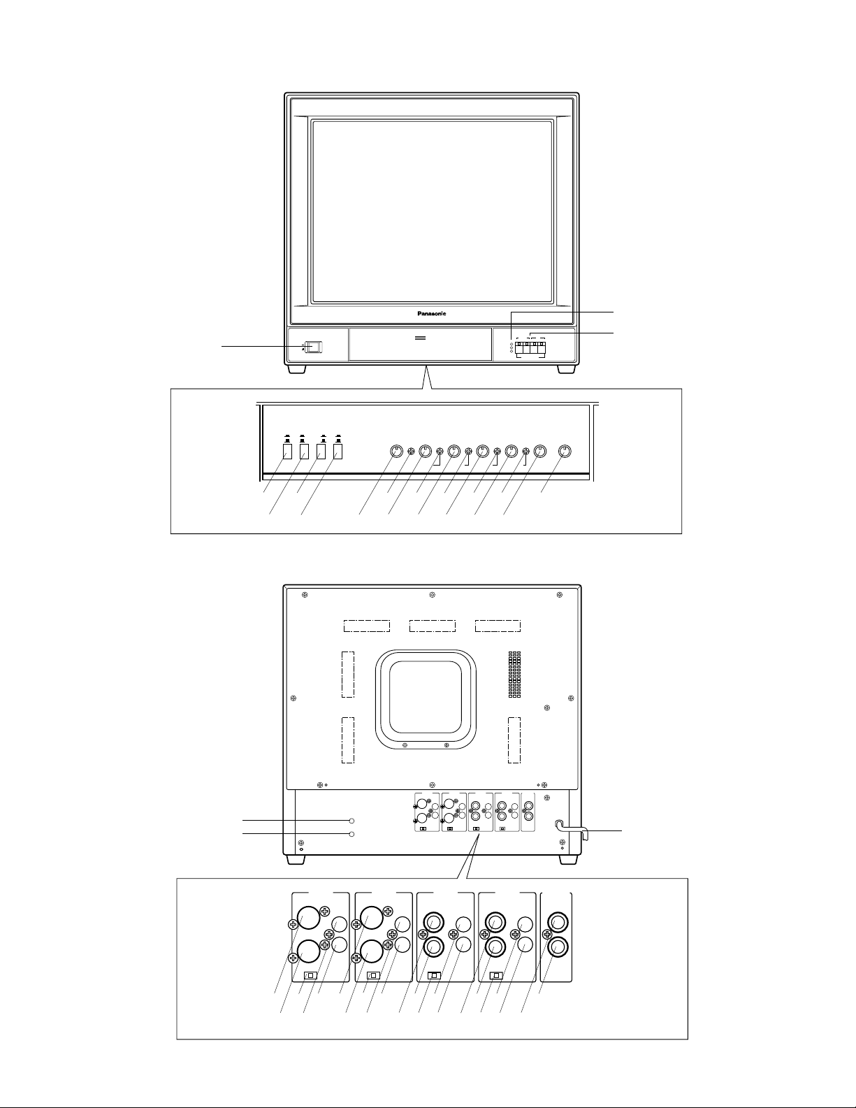
MAJOR OPERATING CONTROLS AND THEIR FUNCTIONS
q
wer
ty
uio
!0
!1
!2
!3 !5
!66
!7
!4
!8
!9
@3
@2 @4
@5
@6
@8
@7 @9
#0
#1
#2
#3 #5
#4 #6
#7
#8
$2
$3 $0
#9 $1
@0
@1
$4
STAND
POWER
ON
OFF
ON
LONG
OFFONNARROW
OFF
SHORT
WIDE
3.58
AFC
TRAP
PICTURE
BY
V-HOLD H-HOLD
PUSH
Video Monitor WV-CM 2000
COLOUR BRIGHT CONTRAST PICTURE AUDIO
TINT
VIDEO Y/C
1 2 3 4
PAL
NTSC
(3.58)
M.NTSC
(4.43)
INPUT SELECT
MIN MAX
INPUT 4
S-VIDEOINAUDIO
FOCUS
IN
INPUT 3
S-VIDEOINAUDIO
IN
INPUT 4
S-VIDEOINAUDIO
IN
OUT
OUT
Hiz
INPUT 2
VIDEOINAUDIO
S-VIDEOINAUDIO
OUT
75Ω75Ω 75Ω 75ΩHiz
INPUT 3
INPUT 2
VIDEOINAUDIO
IN
IN
OUT
OUT OUT
OUT
Hiz
INPUT 1
VIDEOINAUDIO
IN
INPUT 1
VIDEOINAUDIO
IN
OUT
OUT
Hiz
STAND BY
IN
IN
STAND BY
IN
OUT
75Ω 75Ω75Ω75ΩHiz
OUT
OUT
Hiz
OUT
OUT
OUT OUT
OUT
Hiz
OUT
Hiz
Page 5

-3-
1. Power Switch (POWER ON/OFF)
This is a push-push type switch which turns the power
of the monitor on and off.
Press once and the switch remains down (
) for turning on the power of monitor.
Press again, the switch comes up (
) for turning off
the power of the monitor.
2. Stand-by On/Off Switch (STAND BY ON/OFF)
This is a push-push type switch which turns on/off this
switch.
Press once and the switch remains down (
) for turning on this switch.
Press again, the switch comes up (
) for turning off
this switch.
When selecting the Standby On/Off mode by using the
external signal, set this switch to the ON position.
3. AFC time Selection Switch (AFC, LONG/SHORT)
This is a push-push type switch which selects the AFC
time. Press once, then the switch remains down (
)
for selecting the LONG position.
Press again, then the switch comes up (
) for selecting the SHORT position.
Normally (standard video signal), set this switch to the
SHORT position.
When the video signal is jittery, set this switch to the
LONG position.
4. 3.58 MHz Trap Filter On/Off Switch
(3.58 TRAP, ON/OFF)
This is a push-push type switch which turns on/off the
3.58 MHz Trap Filter.
Press once, then the switch remains down (
) for
tuning off the 3.58 MHz Trap Filter.
Press again, then the switch remains down (
) for
turning on the 3.58 MHz Trap Filter function.
Note: When decreasing the colour dots noise on the
monitor screen, turn on this switch.
5. Picture Selection Switch (PICTURE NARROW/
WIDE)
NARROW: Select this position when the video source
is come from the high resolution camera or the
like.
WIDE: Select this position when the video source is
come from the low resolution VTR.
6. Vertical Hold Control (V-HOLD)
This control is used to adjust the picture in vertically.
7. Horizontal Hold Control (H-HOLD)
This control is used to lock the picture in horizontally.
8. Tint Control (TINT)
Turn this control clockwise for purplish colour of the
picture and turn this counterclockwise for greenish
colour of the picture.
9. Tint Subcontrol
10. Colour Control (COLOUR)
Turn this control clockwise to increase the picture
colour and turn this control counterclockwise to
decrease the picture colour.
11. Colour Subcontrol
12. Bright Control (BRIGHT)
Turn this control clockwise to increase the picture
brightness and turn this control counterclockwise to
decrease the picture brightness.
13. Bright Subcontrol
14. Contrast Control (CONTRAST)
Turn this control clockwise to increase the picture contrast and turn this control counterclockwise to
decrease the picture contrast.
15. Contrast Subcontrol
16. Picture Adjustment (PICTURE)
Turn this control clockwise for sharp picture and turn
this control counterclockwise for soft picture.
17. Audio Volume (AUDIO, MIN/MAX)
Turn this volume clockwise to increase the audio level
and turn this volume counterclockwise to decrease the
audio level.
18. Power Indicator/Broadcast System Indicator
(PAL, NTSC, M-NTSC)
When turning on the power of this monitor without any
input signals, PAL LED indicator lights in red.
The NTSC LED indicator lights in green with the NTSC
input signal.
The M-NTSC LED indicator light in orange with the MNTSC input signal.
These indicators are switched by the difference in the
broadcasting system connected to this monitor.
In the Stand-by mode, PAL and NTSC LEDs light
together.
19. Input Signal Selection Switches (INPUT 1/2/3/4)
By pressing the desired switch, both Video (S-Video)
and Audio input signals are selected.
Note : The video and audio input signal selected once
will be kept even if the power of this monitor is
turned off.
20. Focus Control (FOCUS)
POWER
ON
OFF
VIDEO Y/C
1 2 3 4
PAL
NTSC
(3.58)
M.NTSC
(4.43)
INPUT SELECT
Page 6

-4-
21. Screen Control
This control is preset at the factory.
Do not adjust this control.
When the adjustment of this control is required, refer
to the qualified service personnel.
22. S-Video Input Connector (INPUT 4, S-VIDEO IN)
This connector accepts a S-Video (PAL/NTSC) signal.
23. S-Video Output Connector (INPUT 4, S-VIDEO OUT)
The S-Video input signal connected to the S-Video
Input Connector (22) is looped through to this connector.
24. S-Video Termination Switch (INPUT 4, 75Ω/Hi-z)
When bridging or looping through the S-Video signal,
set this switch to Hi-z position, and other cases this
switch should be set to 75Ω position.
25. Audio Input Connector (INPUT 4, AUDIO IN)
−8 dB/Hi-z audio signal can be supplied to this input
connector.
26. Audio Output Connector (INPUT 4, AUDIO OUT)
The audio input signal connected to the Audio Input
Connector (25) is looped through to this connector.
27. S-Video Input Connector (INPUT 3, S-VIDEO IN)
This connector accepts a S-Video (PAL/NTSC) signal.
28. S-Video Output Connector (INPUT 3, S-VIDEO OUT)
The S-Video input signal connected to the S-Video
Input Connector (27) is looped through to this connector.
29. S-Video Termination Switch (INPUT 3, 75Ω/Hi-z)
When bridging or looping through the video signal, set
this switch to Hi-z position, and other cases this switch
should be set to 75Ω position.
30. Audio Input Connector (INPUT 3, AUDIO IN)
−8 dB/Hi-z audio signal can be supplied to this input
connector.
31. Audio Output Connector (INPUT 3, AUDIO OUT)
The audio input signal connected to the Audio Input
Connector (30) is looped through to this connector.
32. Video Input Connector (INPUT 2, VIDEO IN)
This connector accepts a composite PAL/NTSC/MNTSC video signal.
33. Video Output Connector (INPUT 2, VIDEO OUT)
The video input signal connected to the Video Input
Connector (32) is looped through to this connector.
34. Video Termination Switch (INPUT 2, 75Ω/Hi-z)
When bridging or looping through the video signal, set
this switch to Hi-z position, and other cases this switch
should be set to 75Ω position.
35. Audio Input Connector (INPUT 2, AUDIO IN)
−8 dB/Hi-z audio signal can be supplied to this input
connector.
36. Audio Output Connector (INPUT 2, AUDIO OUT)
The audio input signal connected to the Audio Input
Connector (35) is looped through to this connector.
37. Video Input Connector (INPUT 1, VIDEO IN)
This connector accepts a composite PAL/NTSC/MNTSC video signal.
38. Video Output Connector (INPUT 1, VIDEO OUT)
The video input signal connected to the Video Input
Connector (37) is looped through to this connector.
39. Video Termination Switch (INPUT 1, 75Ω/Hi-z)
When bridging or looping through the video signal, set
this switch to Hi-z position, and other cases this switch
should be set to 75Ω position.
40. Audio Input Connector (INPUT 1, AUDIO IN)
−8 dB/Hi-z audio signal can be supplied to this input
connector.
41. Audio Output Connector (INPUT 1, AUDIO OUT)
The audio input signal connected to the Audio Input
Connector (40) is looped through to this connector.
42. Standby Input Connector (STAND BY IN)
Supply the control signal to select the Standby On/Off
mode to this connector.
Only when setting the Stand-by On/Off Switch to the
ON position, this control signal can be functioned.
When the coaxial cable from this connector is grounded, the picture is appeared on the screen.
43. Standby Output Connector (STAND BY OUT)
This connector is looped through to the Standby Input
Connector(42).
44. Power Cord
CAUTION: The supplied power cord is designed for
use on the supplied 220-240V AC supply only.
Page 7

-5-
CABLE INFORMATIONS
Power Cord
1. Keep the Power Switch (1) in the OFF position during
installation.
2. Connect the Power Cord to a grounded electrical outlet.
Video Cable
1. Use 75-ohm coaxial cable [RG-59/U (3C-2V), RG-6/U
(5C-2V), RG-14/U (7C-2V), RG-15/U (10C-2V)]
2. Up to 10 monitors can be hooked up in this configuration before signal loss occurs. Total cable length
should not exceed 150m.
3. Wiring Precautions :
• Do not bend coaxial cable into a curve whose
radius is smaller than 10 times of its diameter.
• Never crush or pinch the cable.
All these will change the impedance of the cable and
cause poor picture quality.
Type of RG-59/U RG-6U RG-11/U RG-15/U
coaxial cable (3C-2V) (5C-2V) (7C-2V) (10C-2V)
Recommended (ft) 825 1,650 1,980 2,640
maximum
cable length (m) 250 500 600 800
Page 8

-6-
SYSTEM CONNECTIONS
1. Single Monitor Connection
• Connect the coaxial cable between the S-Video
Output connector of the camera or VTR and the SVideo Input Connector (22) or (27) of this monitor.
• Connect the coaxial cable between the Video Output
connector of the camera or VTR and the Video Input
Connector (32) or (37) of this monitor.
• Set the S-Video Termination Switch (24) or (29) to
75Ωposition.
• Set the Video Termination Switch (34) or (39) to 75Ω
position.
• Connect the coaxial cable to the Standby Input
Connector (42) when the Standby On/Off mode is
selected by the external signal.
2. Multiple Monitor Connection
• Connect the coaxial cable between the S-Video or
Video Output terminal of the camera or VTR and the SVideo or Video Input Connector (22), (27), (32) or (37)
of this monitor.
• Connect the coaxial cable between the S-Video/Video
Output Connector (23), (28), (33) or (38) on the first
monitor and the S-Video/Video Input Connector (22),
(27), (32) or (37) on the second monitor, and continue
until all monitors are connected.
• Set the S-Video/Video Termination Switch (24), (29),
(34) or (39) of the first and intermediate monitors to HiZ position. Then set the S-Video/Video Termination
Switch (24), (29), (34) or (39) of the last monitor to 75Ω
position.
• Connect the coaxial cable to the Standby Input
Connector (42) when the Standby On/Off mode is
selected by the external signal.
• Connect the coaxial cable between the Standby
Output Connector (43) on the first monitor and the
Standby Input Connector (42) on the second monitor,
and continue until all monitors are connected.
3. Audio Circuit Signal
• Connect the coaxial cable between the Video or SVideo Output connector of VTR or camera and the SVideo/Video Input Connector (22), (27), (32) or (37) on
this monitor.
• Connect the audio cable between the Audio Output
Connector of VTR and the Audio Input Connector (25),
(30), (35) or (40) of this monitor, and connect the
audio cable between the Audio Input Terminal of
audio amplifier to the Audio Output Connector (26),
(31), (36) or (41) of this monitor.
• Set the S-Video/Video Termination Switch (24), (29),
(34), or (39) to 75Ω position.
VIDEO OUT
AC Mains
AC Mains
AC Mains
AC Mains
VTR/Video Disc Player
Camera
Camera
Speaker
Amp
Coax.
Cable
Coax.
Cable
Coax.
Cable
Coax.
Cable
S-VIDEO
OUT
S-VIDEO
OUT
S-VIDEO
OUT
S-VIDEO
OUT
AUDIO
OUT
FOCUS
75Ω Hiz
S-VIDEOINAUDIO
OUT
75Ω 75Ω 75Ω 75ΩHiz
INPUT 4
IN
OUT
INPUT 3
INPUT 2
VIDEOINAUDIO
S-VIDEOINAUDIO
IN
IN
OUT
OUT OUT
OUT
OUT
Hiz
Hiz
75Ω Hiz
VIDEOINAUDIO
OUT
STAND BY
INPUT 1
IN
IN
OUT
Hiz
75Ω Hiz
FOCUS
INPUT 4
INPUT 3
S-VIDEOINAUDIO
S-VIDEOINAUDIO
IN
OUT
OUT
OUT
Hiz
75Ω75Ω 75Ω 75ΩHiz
75Ω Hiz
IN
OUT
INPUT 2
VIDEOINAUDIO
IN
OUT
OUT OUT
Hiz
VIDEOINAUDIO
OUT
STAND BY
INPUT 1
IN
IN
OUT
Hiz
FOCUS
75Ω Hiz
FOCUS
75Ω Hiz
INPUT 4
S-VIDEOINAUDIO
OUT
INPUT 4
S-VIDEOINAUDIO
OUT
75Ω 75Ω 75Ω 75ΩHiz
INPUT 3
INPUT 2
STAND BY
INPUT 1
VIDEOINAUDIO
VIDEOINAUDIO
S-VIDEOINAUDIO
IN
IN
IN
OUT
Hiz
IN
IN
OUT
OUT OUT
OUT
OUT
OUT
OUT
75Ω75Ω 75Ω 75ΩHiz
Hiz
Hiz
INPUT 3
INPUT 2
STAND BY
INPUT 1
VIDEOINAUDIO
VIDEOINAUDIO
S-VIDEOINAUDIO
IN
IN
IN
OUT
IN
IN
OUT
OUT OUT
OUT
OUT
OUT
OUT
Hiz
Hiz
Hiz
Page 9
-7-
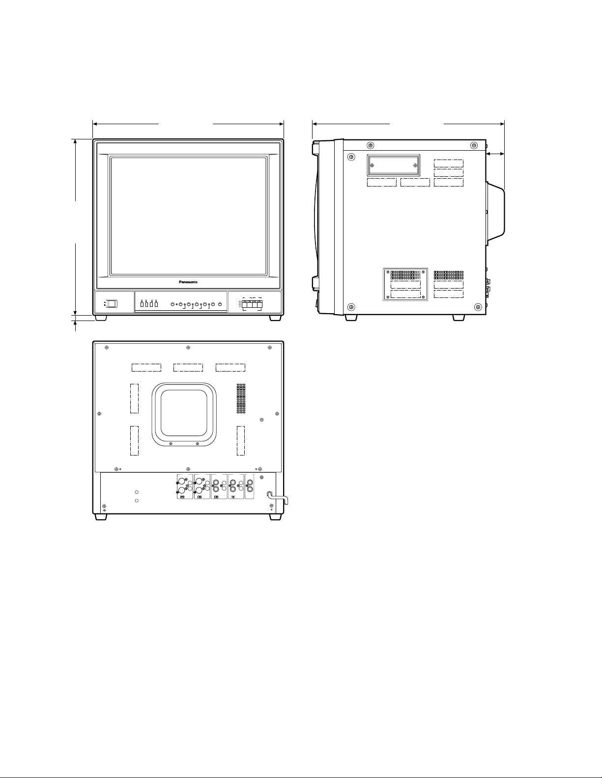
APPEARANCE
Unit: mm (inches)
500 (19-11/16)
49
(1-13/16)
500 (19-11/16)
460 (18-1/8)
14 (9/16)
POWER
ON
OFF
ON
LONG
OFFONNARROW
OFF
SHORT
WIDE
3.58
STAND
AFC
BY
TINT
V-HOLD H-HOLD
PICTURE
TRAP
COLOUR BRIGHT CONTRAST PICTURE AUDIO
MIN MAX
VIDEO Y/C
1 2 3 4
PAL
NTSC
(3.58)
M.NTSC
(4.43)
INPUT SELECT
INPUT 4
INPUT 3
INPUT 2
S-VIDEOINAUDIO
FOCUS
OUT
VIDEOINAUDIO
S-VIDEOINAUDIO
IN
IN
OUT
OUT
OUT
OUT
75Ω75Ω 75Ω 75ΩHiz
Hiz
Hiz
INPUT 1
VIDEOINAUDIO
IN
IN
OUT OUT
OUT
OUT
Hiz
STAND BY
IN
Page 10

-8-
SPECIFICATIONS
Power Source : WV-CM2000/A, WV-CM2000/B, WV-CM2000/G: 220 - 240V AC 50Hz
Power Consumption : Approx. 99 watts
Video Input/Output : 1.0 Vp-p composite/75 ohms or Hi-z looping through
S-Video Input/Output : Y : 1.0 Vp-p/75 ohms or Hi-z looping through (PAL/NTSC)
C : 0.3 Vp-p 75 ohms or Hi-z looping through (PAL)
C : 0.286 Vp-p 75-ohms Hi-z looping through (NTSC)
Scanning Size : Approx. 8%
CRT Size : 54.8 cm (21" diagonal)
Actual Visual Size : 51 cm (20-1/16" diagonal)
Audio Input/Output : −8dB/Hi-z
Speaker Output : 1.3 watts
Resolution : 500 lines or more (at centre)
Sweep Linearity : Horizntal : 5% or less
Vertical : 5% or less
Sweep Giometory : 2% or less
Stand-by : Manual/External control
AFC Speed : Short/Long switchable
3.58 MHz Trap : On/Off switchable
Picture Selection : Narrow/Wide switchable
Ambient Operating Temperature : −10°C - +50°C (14°F - 122°F)
Ambient Operating Humidity : Less than 90%
Dimensions : 500 (W) x 474 (H) x 500 (D) mm
19-11/16”(W) x 18-11/16”(H) x 19-11/16”(D)
Weight : 30 kg (66 lbs.)
Weight and dimensions shown are approximate.
Specifications are subject to change without notice.
Page 11

-9-
DEUTSCHE AUSGABE
(GERMAN VERSION)
VORWORT ....................................................................... 10
MERKMALE ..................................................................... 10
VORSICHTSMASSNAHMEN ........................................... 10
WICHTIGE BEDIENUNGSELEMENTE UND
IHRE FUNKTIONEN ................................................... 11
KABEL-INFORMATIONEN .............................................. 14
SYSTEMANSCHLÜSSE ................................................... 15
MASSZEICHNUNG ......................................................... 16
TECHNISCHE DATEN ..................................................... 17
INHALT
DEUTSCH
Das Blitzzeichen mit Pfeil im gleichseitigen Dreieck soll den Benutzer auf das
Vorhandensein von nichtisolierter "gefährlicher Spannung" innerhalb des Gehäuses hinweisen, die so groß sein
kann, daß sie Gefahr eines elektrischen
Schlags darstellt.
Das Ausrufezeichen im gleichseitigen
Dreieck soll den Benutzer auf wichtige
Bedienungs- und Wartungsanweisungen in den Unterlagen hinweisen, die
dem Gerät beiliegen.
Die Fabriknummer dieses Gerätes ist auf dessen Bodenabdeckung angegeben.
Sie sollten die Fabriknummer dieses Gerätes in den
dafür vorgesehenen Raum eintragen und diese
Anleitung als Kaufsunterlage aufbewahren, um im Falle
eines Diebstahls die ldentifizierung zu erleichtern.
Modellnummer
Fabriknummer
WARNUNG: UM DIE GEFAHR VON BRAND ODER STROMSCHLAG ZU VERHÜTEN, DIESES GERÄT WEDER REGEN
NOCH FEUCHTIGKEIT AUSSETZEN.
WARNUNG:
WEDER DECKEL NOCH RÜCKPLATTE ABNEHMEN,
UM DIE GEFAHR EINES ELEKTRISCHEN SCHLAGS
ZU VERMEIDEN. DAS GERÄT ENTHÄLT KEINE
BAUTEILE, DIE VOM KUNDEN GEWARTET WERDEN
KÖNNEN.
CAUTION
RISK OF ELECTRIC SHOCK
DO NOT OPEN
HINWEIS:
Die in diesem Gerät entstehende Röntgenstrahlung ist
ausreichend abgeschirmt. Beschieunigungsspannung
mas. 29,5 kV.
Wir erklären in alleiniger Verantwortung, daß das Produkt,
auf das sich diese Erklärung bezieht, mit der folgenden
Normen oder normativen Dokumenten übereinstimmt.
Gemäß den Bestimmungen der Richtlinite 89/336/EEC.
Die in dieser Bedienungsanleitung aufgeführten Modellnummern weisen keinen Anhang auf.
Page 12

-10-
VORWORT
Der für PAL/NTSC/M-NTSC (modifiziertes NTSC-Signal)
vorgesehene Farbmonitor WV-CM2000 von Panasonic
zeichnet sich durch eine hohe Auflösung aus, um scharfe
Bilder in hoher Qualität zu gewährleisten.
Mit Ausnahme des Netzschalters und EingangssignalWahlschalters sind alle anderen Bedienungselemente mit
einer Klappe abgedeckt, um der Frontseite ein schlankes
Aussehen zu verleihen. Die Hauptregler für Farbton,
Farbsättigung, Helligkeit und Kontrast sind mit Hilfsreglern
versehen, die eine Einstellung der vorgegebenen Pegel
gestatten.
Standard-BNC- und S-Video-Eingangs- und -Ausgangssteckverbinder ermöglichen die Verwendung des Modells
WV-CM2000 mit anderen CCTV-Monitoren oder Panasonic
Videorecordern.
MERKMALE
• 54,8 cm (21 Zoll Diagonale)
• Umschaltbare AFC-Zeitkonstante
• Durchschleifen durch BNC-Steckverbinder für VideoEingang und -Ausgang
• Durchschleifen durch S-Video-Steckverbinder für SVideo-Eingang und -Ausgang
• Durchschleifen durch Cinch-Buchsen für AudioEingang und -Ausgang
• PAL/NTSC/M-NTSC wählbar
• 3,58MHz-Sperrfilter-Ein/Aus-Schalter für NTSC
• Ausgerüstet mit Bereitschafts-Ein/Aus-Schalter für
Energieeinsparung
• Ausgerüstet mit Bildwahlschalter
• Lautsprecher-Ausgangsleistung max. 1,3 W
• Kanäle 1 - 4 für Eingangs- und Ausgangssignale
wählbar
VORSICHTSMASSNAHMEN
• Niemals die Belüftungsschlitze abdecken.
• Den Video-Monitor so aufstellen, daß ein Abstand von
mindestens 5 cm zur Wand eingehalten wird.
• Den Monitor niemals Wasser oder Feuchtigkeit aussetzen.
• Den Monitor nicht betreiben, wenn dieser naß wird.
• Falls der Monitor naß wird, sofort geeignete
Gegenmaß nahmen treffen. Die Stromversorgung
ausschalten, und den Monitor von einem qualifizierten
Wartungstechniker überprüfen lassen.
Feuchtigkeit kann den Monitor beschädigen und zu
elektrischen Schlägen führen.
• Keine Metallteile durch die Belüftungsschlitze fallen
lassen, da sonst der Monitor permanent beschädigt
werden kann. Sofort die Stromversorgung ausschalten, und den Monitor von einem qualifizierten
Wartungstechniker überprüfen lassen.
• Niemals den Monitor zu zerlegen versuchen.
Schrauben und Deckel dürfen nicht abgenommen
werden, um elektrischen Schlägen vorzubeugen. Im
Inneren des Gerätes befinden sich keine vom
Anwender zu wartenden Teile. Wartungsarbeiten nur
von einem qualifizierten Wartungstechniker ausführen
lassen.
• Bei der Verwendung des Monitors immer die
zulässige Temperatur, Luftfeuchtigkeit und Stromquelle einhalten.
(a) Die Umgebungstemperatur muß im Bereich von
−10°C bis +50°C liegen.
(b) Den Monitor nicht verwenden, wenn die Luft-
feuchtigkeit mehr als 90% beträgt.
(c) Der Monitor darf nur mit Netzstrom von 220 - 240
V, 50 Hz, betrieben werden.
Page 13

-11-
WICHTIGE BEDIENUNGSELEMENTE UND IHRE FUNKTIONEN
q
wer
ty
uio
!0
!1
!2
!3 !5
!66
!7
!4
!8
!9
@3
@2 @4
@5
@6
@8
@7 @9
#0
#1
#2
#3 #5
#4 #6
#7
#8
$2
$3 $0
#9 $1
@0
@1
$4
STAND
POWER
ON
OFF
ON
LONG
OFFONNARROW
OFF
SHORT
WIDE
3.58
AFC
TRAP
PICTURE
BY
V-HOLD H-HOLD
PUSH
Video Monitor WV-CM 2000
COLOUR BRIGHT CONTRAST PICTURE AUDIO
TINT
VIDEO Y/C
1 2 3 4
PAL
NTSC
(3.58)
M.NTSC
(4.43)
INPUT SELECT
MIN MAX
INPUT 4
S-VIDEOINAUDIO
FOCUS
IN
INPUT 3
S-VIDEOINAUDIO
IN
INPUT 4
S-VIDEOINAUDIO
S-VIDEOINAUDIO
IN
OUT
OUT
Hiz
75Ω75Ω 75Ω 75ΩHiz
INPUT 2
VIDEOINAUDIO
INPUT 3
IN
OUT
OUT
IN
INPUT 2
VIDEOINAUDIO
IN
OUT
OUT OUT
Hiz
VIDEOINAUDIO
INPUT 1
VIDEOINAUDIO
OUT
Hiz
INPUT 1
STAND BY
IN
IN
OUT
STAND BY
IN
IN
OUT
75Ω 75Ω75Ω75ΩHiz
OUT
OUT
Hiz
OUT
OUT
Hiz
OUT OUT
OUT
OUT
Hiz
Page 14

-12-
1. Netzschalter (POWER ON/OFF)
Hierbei handelt es sich um einen Drucktastenschalter,
mit dem die Stromversorgung des Monitors ein- und
ausgeschaltet wird.
Den Schalter durch einmaliges Drücken einrasten
(
), um die Stromversorgung des Monitors einzuschalten.
Den Schalter durch nochmaliges Drücken ausrasten
(
), um die Stromversorgung auszuschalten.
2. Bereitschafts-Ein/Aus-Schalter
(STAND BY ON/ OFF)
Dieser Drucktastenschalter dient für das Ein- und
Ausschalten der Bereitschaftsfunktion.
Den Schalter durch einmaliges Drücken einrasten
(
), um die Bereitschaftsfunktion einzuschalten.
Den Schalter durch nochmaliges Drücken ausrasten
(
) um die Bereitschaftsfunktion auszuschalten.
Wenn der Bereitschafts-Ein/Aus-Modus unter Verwendung eines externen Signals gewählt wird, diesen
Schalter auf die Position ON stellen.
3. AFC-Zeitwahlschalter (AFC, LONG/SHORT)
Mit diesem Drucktastenschalter wird die AFC-Zeit
gewählt. Den Schalter durch einmaliges Drücken einrasten (
), um die lange Horizontalzeit (LONG) zu
wählen.
Den Schalter durch nochmaliges Drücken ausrasten
(
), um die kurze Horizontalzeot (SHORT) zu wählen.
Diesen Schalter normalerweise (normales Videosignal)
auf die kurze Horizontalzeit (SHORT) einstellen.
Falls das Videosignal Synchronisationsstörungen
aufweist, diesen Schalter auf die lange Horizontalzeit
(LONG) einstellen.
4. 3,58MHz-Sperrfilter-Ein/Aus-Schalter
(3.58 TRAP, ON/OFF)
Dieser Drucktastenschalter dient zum Ein- und Ausschalten des 3,58MHz-Sperrfilters.
Den Schalter durch einmaliges Drücken einrasten
(
), um das 3,58MHz-Sperrfilter auszuschalten.
Den Schalter durch nochmaliges Drücken ausrasten
(
), um das 3,58MHz-Sperrfilter einzuschalten.
Hinweis: Um das Farbpunktrauschen am Monitor-
Bildschirm zu vermindern, diesen Schalter einschalten.
5. Bildwahlschalter (PICTURE NARROW/WIDE)
NARROW: Diese Position wählen, wenn die Video-
quelle eine Kamera mit hoher Auflösung oder dgl.
ist.
WIDE: Diese Position wählen, wenn die Videoquelle
ein Videorecorder mit niedriger Auflösung ist.
6. Vertikaler Bildfangregler (V-HOLD)
Dieser Regler wird verwendet, um ein vertikal durchlaufenden Bild zu stebilisieren.
7. Horizontaler Bildfangregler (H-HOLD)
Dieser Regler wird verwendet, ium das Bild horizontal
zu verriegeln.
8. Farbtonregler (TINT)
Diesen Regler für ein rotstichiges Bild im
Uhrzeigersinn bzw. für ein grünstichiges Bild entgegen dem Uhrzeigersinn drehen.
9. Farbton-Hilfsregler
10. Farbsättigungsregler (COLOUR)
Diesen Regler zum Erhöhen der Farbsättigung des
Bildes im Uhrzeigersinn bzw. zum Verringern der
Farbsättigung des Bildes entgegen dem
Uhrzeigersinn drehen.
11. Farbsättigungs-Hilfsregler
12. Helligkeitsregler (BRIGHT)
Diesen Regler zum Erhöhen der Helligkeit des Bildes
im Uhrzeigersinn bzw. zum Verringern der Helligkeit
des Bildes entgegen dem Uhrzeigersinn drehen.
13. Helligkeits-Hilfsregler
14. Kontrastregler (CONTRAST)
Diesen Regler zum Erhöhen des Bildkontrastes im
Uhrzeigersinn bzw. zum Verringern des
Bildkonstrastes entgegen dem Uhrzeigersinn drehen.
15. Kontrast-Hilfsregler
16. Regler für Bildeinstellung (PICTURE)
Diesen Regler für ein scharfes Bild im Uhrzeigersinn
bzw. für ein weiches Bild entgegen dem
Uhrzeigersinn drehen.
17. Lautstärkeregler (AUDIO, MIN/MAX)
Diesen Regler zum Erhöhen des Lautstärkepegels im
Uhrzeigersinn bzw. zum Absenken des Lautstärkepegels entgegen dem Uhrzeigersinn drehen.
18. Einschaltanzeige/Sendesystemanzeige
(PAL, NTSC, M-NTSC)
Wenn die Stromversorgung dieses Monitors ohne
Eingangssignale eingeschaltet wird, leuchtet die PALLeuchtdiodenanzeige rot auf.
Die NTSC-Leuchdiodenanzeige leuchtet grün auf,
wenn das NTSC-Eingangssignal anliegt.
Die M-NTSC-Leuchtdiodenanzeige leuchtet orangefarben auf, wenn das M-NTSC-Eingangssignal anliegt.
POWER
ON
OFF
VIDEO Y/C
1 2 3 4
PAL
NTSC
(3.58)
M.NTSC
(4.43)
INPUT SELECT
Page 15

-13-
Diese Anzeigen werden durch die Unterschiede zwischen den an diesen Monitor angeschlossenen
Sendesysteme umgeschaltet.
In dem Bereitschafts-Ein-Modus leuchten die PALund NTSC-LEDs gleichzeitig.
19. Eingangssignal-Wahlschalter (INPUT 1/2/3/4)
Durch Drücken des gewünschten Schalters werden
die Video- (S-Video) und audio-Eingangssignale
gewählt.
Hinweis: Die gewählten Video- und Audio-Eingangs-
signale werden auch erhalten, wenn die
Stromversorgung des Monitors aus- und danach
wieder eingeschaltet wird.
20. Fokussierregler (FOCUS)
21. Bildschirmregler
Dieser Regler wurde im Werk voreingestellt.
Diesen Regler nicht verstellen.
Wenn eine Einstellung dieses Reglers erforderlich ist,
wenden Sie sich bitte an einen qualifizierten
Wartungstechniker.
22. S-Video-Eingangssteckverbinder
(INPUT 4, S-VIDEO IN)
Ein S-Video-Signal (PAL/NTSC) kann an diesen
Eingangs-Steckverbinder angelegt werden.
23. S-Video-Ausgangssteckverbinder
(INPUT 4, S-VIDEO OUT)
Das an den S-Video-Eingangssteckverbinder (22)
angelegte S-Video-Eingangssignal wird an diesen
Steckverbinder durchgeschleift.
24. S-Video-Abschluß schalter (INPUT 4, 75Ω/Hi-z)
Für das Überbrücken oder Durchschleifen des SVideo-Signals ist dieser Schalter auf die Position Hi-z
einzustellen; für andere Fälle sollte dieser Schalter auf
die Position 75Ω eingestellt werden.
25. Audio-Eingangssteckverbinder
(INPUT 4, AUDIO IN)
Das −8dB/Hi-z-Audio-Signal kann an diesen Eingangssteckverbinder angelegt werden.
26. Audio-Ausgangssteckverbinder
(INPUT 4, AUDIO OUT)
Das an den Audio-Eingangssteckverbinder (25)
angelegte Audio-Eingangssignal wird an diesen
Steckverbinder durchgeschleift.
27. S-Video-Eingangssteckverbinder
(INPUT 3, S-VIDEO IN)
Ein S-Video-Signal (PAL/NTSC) kann an diesen
Eingangssteckverbinder angelegt werden.
28. S-Video-Ausgangssteckverbinder
(INPUT 3, S-VIDEO OUT)
Das an den S-Video-Eingangssteckverbinder (27)
angelegte S-Video-Eingangssignal wird an diesen
Steckverbinder durchgeschleift.
29. S-Video-Abschluß schalter (INPUT 3, 75Ω/Hi-z)
Für das Überbrücken oder Durchschleifen des des
Video-Signals ist dieser Schalter auf die Position Hi-z
einzustellen; für andere Fälle sollte dieser Schalter auf
die Position 75Ω eingestellt werden.
30. Audio-Eingangssteckverbinder
(INPUT 3, AUDIO IN)
Das −8dB/Hi-z-Audio-Signal kann an diesen Eingangssteckverbinder angelegt werden.
31. Audio-Ausgangssteckverbinder
(INPUT 3, AUDIO OUT)
Das an den Audio-Eingangssteckverbinder (30)
angelegte Audio-Eingangssignal wird an diesen
Steckverbinder durchgeschleift.
32. Video-Eingangssteckverbinder
(INPUT 2, VIDEO IN)
Ein PAL/NTSC/M-NTSC-Video-Signalgemisch kann an
diesen Eingangssteckverbinder angelegt werden.
33. Video-Ausgangssteckverbinder
(INPUT 2, VIDEO OUT)
Das an den Video-Eingangssteckverbinder (32)
angelegte Video-Eingangssignal wird an diesen
Steckverbinder durchgeschleift.
34. Video-Abschluß schalter (INPUT 2, 75Ω/Hi-z)
Für das Überbrücken oder Durchschleifen des VideoSignals ist dieser Schalter auf die Position Hi-z
einzustellen; für andere Fälle sollte dieser Schalter auf
die Position 75Ω eingestellt werden.
35. Audio-Eingangssteckverbinder
(INPUT 2, AUDIO IN)
Das −8dB/Hi-z-Audio-Signal kann an diesen Eingangssteckverbinder angelegt werden.
36. Audio-Ausgangssteckverbinder
(INPUT 2, AUDIO OUT)
Das an den Audio-Eingangssteckverbinder (35)
angelegte Audio-Eingangssignal wird an diesen
Steckverbinder durchgeschleift.
37. Video-Eingangssteckverbinder
(INPUT 1, VIDEO IN)
Ein PAL/NTSC/M-NTSC-Video-Signalgemisch kann an
diesen Eingangssteckverbinder angelegt werden.
38. Video-Ausgangssteckverbinder
(INPUT 1, VIDEO OUT)
Das an den Video-Eingangssteckverbinder (37)
angelegte Video-Eingangssignal wird an diesen
Steckverbinder durchgeschleift.
39. Video-Abschluß schalter (INPUT 1, 75Ω/Hi-z)
Für das Überbrücken oder Durchschleifen des VideoSignals ist dieser Schalter auf die Position Hi-z
einzustellen; für andere Fälle sollte dieser Schalter auf
die Position 75Ω eingestellt werden.
40. Audio-Eingangssteckverbinder
(INPUT 1, AUDIO IN)
Das −8dB/Hi-z-Audio-Signal kann an diesen Eingangssteckverbinder angelegt werden.
Nur wenn der Bereitschafts-Ein/Aus-Schalter auf
Position ON gestellt ist, kann dieses Steuersignal
angelegt werden.
Page 16

-14-
KABEL-INFORMATIONEN
Netzkabel
1. Den Netzschalter (1) auf die Position OFF einstellen,
während die Anschlüsse hergestellt werden.
2. Das Netzkabel an eine geerdete Netzsteckdose
anschließ en.
Video-Kabel
1. Nur 75-Ohm-Koaxialkabel [RG-59/U (3C-2V), RG-6/U
(5C-2V), RG-14/U (7C-2V), RG-15/U (10C-2V)] verwenden.
2. Bis zu 10 Monitore können in dieser Konfiguration
angeschlossen werden, bevor es zu Signalverlusten
kommt. Die gesamte Kabellänge sollte jedoch 150 m
nicht übersteigen.
3. Vorsichtsmaß nahmen bei der Verdrahtung:
• Beim Abbiegen eines Koaxialkabels muß der
Biegeradius mindestens dem 10-fachen Durchmesser entsprechen.
• Niemals ein Kabel plattdrücken oder einklemmen.
Durch diese Vorgänge wird die Impedanz des Kabels
geändert, was zu einer schlechten Bildqualität führt.
Typ des RG-59/U RG-6U RG-11/U RG-15/U
Koaxial-Kabels (3C-2V) (5C-2V) (7C-2V) (10C-2V)
Empfohlene (ft) 825 1.650 1.980 2.640
max.
Kabellänge (m) 250 500 600 800
Vorsicht: Bas als Zubehör mitgelieferte Netzkabel
ist für eine Netzspannung von 220 bis 240 V
ausgelegt.
41. Audio-Ausgangssteckverbinder
(INPUT 1, AUDIO OUT)
Das an den Audio-Eingangssteckverbinder (40)
angelegte Audio-Eingangssignal wird an diesen
Steckverbinder durchgeschleift.
42. Bereitschafts-Eingangssteckverbinder
(STAND BY IN)
Das Steuersignal anlegen, um den BereitschaftsEin/Aus-Modus dieses Steckverbinders zu wählen.
Wenn das Koaxialkabel von diesem Steckverbinder
geerdet wird, erscheint das Bild am Bildschirm.
43. Bereitschafts-Ausgangssteckverbinder
(STAND BY OUT)
Die Signale werden von dem Bereitschafts-Eingangssteckverbinder (42) an diesen Steckver-binder durchgeschleift.
44. Netzkabel
Page 17

-15-
SYSTEMANSCHLÜSSE
1. Anschluß eines einzigen Monitors
• Den S-Video-Ausgangssteckverbinder der Kamera
oder des Videorecorders mit einem Koxialkabel mit
dem S-Video-Eingangssteckverbinder (22) oder (27)
dieses Monitors verbinden.
• Den Video-Ausgangssteckverbinder der Kamera oder
des Videorecorders mit einem Koaxialkabel mit dem
Video-Eingangssteckverbinder (32) oder (37) dieses
Monitors verbinden.
• Den S-Video-Abschluß schalter (24) oder (29) auf die
Position 75Ω einstellen.
• Den Video-Abschluß schalter (34) oder (39) auf die
Position 75Ω einstellen.
• Ein Koaxialkabel an den Bereitschafts-Eingangssteckverbinder (42) anschließen, wenn der
Bereitschafts-Ein/Aus-Modus durch ein externes
Signal gewählt wird.
2. Anschluß von mehreren Monitoren
• Den S-Video- oder Video-Ausgangssteckverbinder
der Kamera oder des Videorecorders mit einem
Koaxialkabel mit dem S-Video- oder Video-Eingangssteckverbinder (22), (27), (32) oder (37) dieses
Monitors verbinden.
• Den S-Video- oder Video-Ausgangssteckverbinder
(23), (28), (33) oder (38) des ersten Monitors mit
einem Koaxialkabel mit dem S-Video- oder VideoEingangssteckverbinder (22), (27), (32) oder (37) des
zweiten Monitors verbinden. Das Herstellen dieser
Anschlüsse sinngemäß fortsetzen, bis alle Monitore
miteinander verbunden sind.
• Den S-Video- oder Video-Abschluß schalter (24), (29),
(34) oder (39) des ersten Monitors oder der dazwischenliegenden Monitore auf die Position Hi-z einstellen. Dann den S-Video- oder Video-Abschluß
schalter (24), (29), (34) oder (39) des letzten Monitors
auf die Position 75Ω einstellen.
• Ein Koaxialkabel an den Bereitschafts-Eingangssteckverbinder (42) anschließen, wenn der Bereitschafts-Ein/Aus-Modus durch ein externes Signal
gewählt wird.
• Das Koaxialkabel zwischen dem Bereitschafts-Ausgangssteckverbinder (43) des ersten Monitors und
dem Bereitschafts-Eingangssteckverbinder (42) des
zweiten Steckverbinders anschließen, und diese
Anschlüsse sinngemäß fortsetzen, bis alle Monitore
angeschlossen sind.
3. Audio-Schaltkreissignal
• Den Video- oder S-Video-Ausgangssteckverbinder
des Videorecorders oder der Kamera mit einem
Koaxialkabel mit dem S-Video- oder Video-Eingangssteckverbinder (22), (27), (32) oder (37) dieses
Monitors verbinden.
• Den Audio-Ausgangssteckverbinder des Videorecorders mit einem Koaxialkabel mit dem AudioEingangssteckverbinder (25), (30), (35) oder (40)
dieses Monitors verbinden. Auß erdem den AudioEingangssteckverbinder des Tonfrequenzverstärkers
mit einem Koaxialkabel mit dem Audio-Ausgangssteckverbinder (26), (31), (36) oder (41) dieses
Monitors verbinden.
• Den S-Video- oder Video-Abschluß schalter (24), (29),
(34) oder (39) auf die Position 75Ω einstellen.
Kamera
Lautsprecher
Verstärker
Koaxalkabel
Koaxal-
kabel
Netzsteckdose
Netzsteckdose
VIDEO OUT
S-VIDEO
OUT
S-VIDEO
OUT
S-VIDEO
OUT
AUDIO
OUT
Kamera
Koaxalkabel
Koaxalkabel
Netzsteckdose
Videorecorder/Bildplattenspieler
S-VIDEO
OUT
Netzsteckdose
FOCUS
75Ω 75Ω 75Ω 75ΩHiz
75Ω Hiz
S-VIDEOINAUDIO
OUT
INPUT 4
IN
OUT
INPUT 3
INPUT 2
VIDEOINAUDIO
S-VIDEOINAUDIO
IN
IN
OUT
OUT OUT
OUT
OUT
Hiz
Hiz
75Ω Hiz
VIDEOINAUDIO
OUT
STAND BY
INPUT 1
IN
IN
OUT
Hiz
FOCUS
75Ω Hiz
FOCUS
75Ω 75Ω 75Ω 75ΩHiz
75Ω Hiz
S-VIDEOINAUDIO
OUT
S-VIDEOINAUDIO
OUT
INPUT 4
INPUT 3
INPUT 2
STAND BY
INPUT 1
VIDEOINAUDIO
VIDEOINAUDIO
S-VIDEOINAUDIO
IN
IN
OUT
S-VIDEOINAUDIO
OUT
IN
IN
OUT
OUT OUT
OUT
OUT
OUT
75Ω75Ω 75Ω 75ΩHiz
Hiz
Hiz
INPUT 3
INPUT 2
STAND BY
INPUT 1
VIDEOINAUDIO
VIDEOINAUDIO
IN
IN
IN
IN
OUT
OUT OUT
OUT
OUT
OUT
Hiz
Hiz
Hiz
IN
OUT
Hiz
INPUT 4
IN
OUT
FOCUS
75Ω Hiz
INPUT 4
INPUT 3
S-VIDEOINAUDIO
S-VIDEOINAUDIO
IN
OUT
OUT
OUT
Hiz
75Ω75Ω 75Ω 75ΩHiz
75Ω Hiz
IN
OUT
INPUT 2
VIDEOINAUDIO
OUT
OUT OUT
Hiz
STAND BY
INPUT 1
VIDEOINAUDIO
IN
IN
IN
OUT
OUT
Hiz
Page 18

-16-
MASSZEICHNUNG
Einheit: mm
500
49
460
14
500
POWER
ON
OFF
ON
LONG
OFFONNARROW
OFF
SHORT
WIDE
3.58
STAND
AFC
BY
TINT
V-HOLD H-HOLD
PICTURE
TRAP
COLOUR BRIGHT CONTRAST PICTURE AUDIO
MIN MAX
VIDEO Y/C
1 2 3 4
PAL
NTSC
(3.58)
M.NTSC
(4.43)
INPUT SELECT
INPUT 4
INPUT 3
INPUT 2
STAND BY
INPUT 1
VIDEOINAUDIO
Hiz
IN
OUT
IN
OUT
OUT OUT
75Ω75Ω 75Ω 75ΩHiz
VIDEOINAUDIO
OUT
Hiz
IN
IN
OUT
S-VIDEOINAUDIO
S-VIDEOINAUDIO
IN
FOCUS
OUT
OUT
OUT
Hiz
Page 19

-17-
TECHNISCHE DATEN
Stromquelle: WV-CM2000/A, WV-CM2000/B, WV-CM2000/G: 220 - 240 V Netzstrom, 50 Hz
Leistungsaufnahme: Ungefähr 99 Watt
Video-Eingang/Ausgang: 1,0 Vss Signalgemisch/75 Ohm oder Hi-z-Durchschleifung
S-Video-Eingang/Ausgang: Y: 1,0 Vss/75 Ohm oder Hi-z-Durchschleifung (PAL/NTSC)
C: 0,3 Vss/75 Ohm oder Hi-z-Durchschleifung (NTSC)
C: 0,286 Vss/75 Ohm oder Hi-z-Durchschleifung (PAL)
Abtastgröß e: Ungefähr 8%
Kathodenstrahlröhre: 54,8 cm (21 Zoll Diagonale)
Tatsächliche Bildgröße: 51 cm (20-1/16 Zoll Diagonale)
Audio-Eingang/Ausgang: −8 dB/Hiz
Lautsprecher-Ausgang: 1,3 Watt
Auflösung: 500 Zeilen oder mehr (in Bildmitte)
Ablenklinearität: Horizontal : 5% oder weniger
Vertikal : 5% oder weniger
Ablenkgeometrie: 2% oder weniger
Bereitschaft: Manuelle/externe Steuerung
AFC-Zeit: Kurz/lang umschaltbar
3,58 MHz Trap: Ein/Aus umschaltbar
Bildwahl: schmal/breit umschaltbar
Zulässige Betriebstempe-ratur: −10°C bis +50°C
Zulässige Luftfeuchtig-keit: Weniger als 90%
Abmessungen: 500 (B) x 474 (H) x 500 (T) mm
Gewicht: 30 kg
Gewicht und Abmessungen sind ungefähre Angaben.
Änderungen der technischen Daten jederzeit vorbehalten.
Page 20

PRÉFACE ........................................................................ 19
CARACTÉRISTIQUES DOMINANTES ............................. 19
MESURES DE PRÉCAUTION .......................................... 19
PRINCIPAUX ORGANES DE COMMANDE ET
LEURS FONCTIONS .................................................. 20
RENSEIGNEMENTS RELATIFS AUX CÂBLES ................ 23
BRANCHEMENT DE SYSTÈME ....................................... 24
ASPECT EXTÉRIEUR ....................................................... 25
CARACTÉRISTIQUES TECHNIQUES .............................. 26
AVERTISSEMENT: N E J A M AIS EXPOSER CET APPAREIL À LA PLUIE NI LE LAISSER DANS UN LIEU HUMIDE
SOUS PEINE DE CRÉER UN AMORÇAGE ÉLECTRIQUE OU UNE ÉLECTROCUTION.
VERSION FRANÇAISE
(FRENCH VERSION)
L'éclair à extrémité fléchée placé dans
un triangle équilatéral est destiné à attirer l'attention de l'utilisateur sur la présence d'une "tension potentionellement
dangereuse" et non isolée se trouvant
dans les limites du coffret de l'appareil
dont la puissance est suffisante pour
constituer un risque important d'électrocution.
Le point d'exclamation placé dans un
triangle équilatéral sert à attirer l'attention de l'utilisateur sur des instructions
de fonctionnement et d'entretien (de
dépannage) à caractère important dans
la brochure qui accompagne l'appareil.
Le numéro de série de l'appareil se trouve sur la plaque de
fond.
Nous vous conseillons de relever le numéro de série de
votre appareil dans l'espace réservé ci-dessous et de conserver précieusement votre notice d'instructions en tant que
justificatif d'achat aux fins d'identification en cas de vol.
No. de modèle
No. de série
Cet appareil est conforme aux prescriptions de la directive
87/308/C.E.E. (concernant les interférences radio).
La Société PANASONIC-FRANCE, importateur du matériel
MATSUSHITA-JAPON déclare que cet appareil est conforme aux prescriptions de la directive 87/308/ C.C.E. modifiée par la directive 82/499/CEE.
Les numéros de modèle qui sont mentionnés dans les
instructions d'utilisation n'ont aucun suffixe indiqué.
ATTENTION:
POUR ÉVITER TOUT RISQUE D'ÉLECTROCUTION,
LE COUVERCLE (OU LE PANNEAU ARRIÈRE) NE
DOIT JAMAIS ÊTRE DÉMONTÉ. AUCUNE PIÈCE
DESTINÉE À L'UTILISATEUR SE TROUVE À L'INTÉRIEUR DE L'APPAREIL. CONFIER LES RÉGLAGES ET LES RÉPARATIONS À UN DÉPANNEUR PROFESSIONNEL.
CAUTION
RISK OF ELECTRIC SHOCK
DO NOT OPEN
-18-
TABLE DES MATIÈRES
Page 21

-19-
PRÉFACE
Le moniteur vidéo couleur WV-CM2000 Panasonic est un
un modèle à haute résolution et fonction S-VIDEO, ce qui
permet d’obtenir des images à haute définition des signaux PAL/NTSC/M-NTSC (NTSC modifié).
Toutes les commandes, à l’exception de l’interrupteur d’alimentation et du sélecteur de signal d’entrée, sont
masquées par une trappe escamotable par pression afin
de donner à l’appareil des lignes extérieures attrayantes
de sa façade. Les commandes principales de nuance
chromatique, couleur, luminosité et de contraste sont
complétées par des commandes de réglage secondaire
afin de pouvoir effectuer un réglage de niveaux
préprogrammés.
Connecteurs d'entrée et de sortie standard BNC et S-vidéo
permettant au WV-CM2000 d'être utilisé avec d'autres
moniteurs vidéo à circuit fermé ou un magnétoscope
Panasonic.
CARACTÉRISTIQUES DOMINANTES
• 54,8 cm en diagonal.
• Constante de temps de contrôle automatique de
fréquence commutable.
• Bouclage réalisé par connecteurs BNC pour les
entrées et sorties vidéo.
• Bouclé réalisé par connecteurs S-vidéo pour les
entrées et sorties S-vidéo.
• Bouclage réalisé par cordon de raccordement à fiches Cinch pour les entrées et sorties son.
• Standard PAL/NTSC/M-NTSC commutable.
• Interrupteur marche-arrêt de filtre de 3,58 MHz pour le
standard NTSC.
• Interrupteur marche-arrêt de veille aux fins
d'économie d'énergie électrique.
• Présence d'un sélecteur d'image.
• Puissance admissible maximum de haut-parleur de
1,3 W.
• Sélection des canaux 1 à 4 pour les signaux d’entrée
et de sortie.
MESURES DE PRÉCAUTION
• Ne pas obturer les ouvertures d’aération.
• Ne pas approcher le moniteur vidéo couleur plus près
que 5 cm d’un mur.
• Ne jamais exposer le moniteur vidéo couleur à la pluie
ni à l’humidité.
• Ne jamais mettre l’appareil en marche s’il a été
mouillé.
• Prendre immédiatement les mesures qui s’imposent si
le moniteur vidéo couleur a été mouillé. Couper l’alimentation et faire appel aux services d’un dépanneur
professionnel. L’humidité risque d’endommager l’appareil et même de constituer un risque de décharge
électrique.
• Ne laisser tomber aucun objet métallique à l’intérieur
par les fentes d’aération. En effet, ceci risque d’endommager définitivement le moniteur vidéo couleur.
Couper l’alimentation et faire appel aux services d’un
dépanneur professionnel.
• Ne jamais chercher à démonter le moniteur vidéo
couleur. Pour éviter tout risque de décharge
électrique, ne jamais retirer les vis de fixation ni les
couvercles de protection. Aucun composant ni
aucune pièce à l’usage de l’utilisateur n’ont été placés
dans l’appareil. Le dépannage et les réglages doivent
être confiés à un dépanneur professionnel.
• L’appareil doit être mis en service dans des limites de
température, d’humidifté ou d’alimentation pour
lesquelles il a été conçu.
(a) La température ambiante doit se situer entre
−10°C et + 50°C.
(b) Éviter de mettre le moniteur vidéo couleur en ser-
vice en présence d’un taux d’humidité supérieur à
90 %.
(c) Le courant d’alimentation secteur doit être de 220
- 240 V, 50 Hz.
FRANÇAIS
Page 22

-20-
PRINCIPAUX ORGANES DE COMMANDE ET FONCTION
q
wer
ty
uio
!0
!1
!2
!3 !5
!66
!7
!4
!8
!9
@3
@2 @4
@5
@6
@8
@7 @9
#0
#1
#2
#3 #5
#4 #6
#7
#8
$2
$3 $0
#9 $1
@0
@1
$4
STAND
POWER
ON
OFF
ON
LONG
OFFONNARROW
OFF
SHORT
WIDE
3.58
AFC
TRAP
PICTURE
BY
V-HOLD H-HOLD
PUSH
Video Monitor WV-CM 2000
COLOUR BRIGHT CONTRAST PICTURE AUDIO
TINT
VIDEO Y/C
1 2 3 4
PAL
NTSC
(3.58)
M.NTSC
(4.43)
INPUT SELECT
MIN MAX
INPUT 4
S-VIDEOINAUDIO
FOCUS
IN
INPUT 3
S-VIDEOINAUDIO
IN
INPUT 4
S-VIDEOINAUDIO
IN
OUT
OUT
Hiz
INPUT 2
VIDEOINAUDIO
INPUT 3
S-VIDEOINAUDIO
OUT
75Ω75Ω 75Ω 75ΩHiz
OUT
IN
INPUT 2
VIDEOINAUDIO
VIDEOINAUDIO
IN
IN
OUT
OUT OUT
Hiz
INPUT 1
VIDEOINAUDIO
INPUT 1
IN
OUT
OUT
Hiz
STAND BY
IN
IN
STAND BY
IN
OUT
75Ω 75Ω75Ω75ΩHiz
OUT
OUT
Hiz
OUT
OUT
OUT OUT
OUT
Hiz
OUT
Hiz
Page 23

-21-
1. Interrupteur d’alimentation (POWER ON/OFF)
Il s’agit d’un interrupteur marche-arrêt de type pushpush qui permet de mettre l’appareil sous tension et
de l’arrêter.
Une première pression enclenche l’interrupteur (
)),
ce qui met le moniteur vidéo couleur sous tension.
Une seconde pression libère l’interrupteur (
), ce qui
coupe l’alimentation du moniteur vidéo couleur.
2. Interrupteur marche-arrêt de veille
(STAND BY ON/OFF)
Il s'agit d'un interrupteur push-pull qui joue le rôle de
mise en fonction et mise à l'arrêt pour cet interrupteur.
Une première pression de l'interrupteur a pour effet de
l'enclencher (
) et de mettre en fonction.
Une deuxième pression de l'interrupteur a pour effet
de le libérer (
) et de mettre à l'arrêt.
Lorsque le mode de veille est choisi à partir d'un signal extérieur, placer l'interrupteur en position
enclenchée.
3. Sélecteur de constante de temps de contrôle
automatique de fréquence (AFC, LONG/SHORT)
Il s’agit d’un sélecteur de type push-push qui permet
de sélectionner la durée de contrôle automatique de
fréquence. Une première pression du sélecteur l’enclenche (
) et permet de passer en position LONG.
Une seconde pression permet de libérer le sélecteur
(
) et de passer en position SHORT.
Normalement, (signal vidéo standard) le sélecteur doit
être placé en position SHORT.
Si une instabilité verticale de l’image se manifeste,
placer le sélecteur en position LONG.
4. Interrupteur marche-arrêt de filtre 3,58 MHz
(3.58 TRAP, ON/OFF)
Il s’agit d’un interrupteur marche-arrêt de type pushpush qui permet de mettre le filtre 3,58 MHz en fonction ou de l’arrêter.
Une première pression enclenche l’interrupteur (
),
ce qui met le filtre 3,58 MHz hors service.
Une seconde pression libère l’interrupteur (
), ce qui
met le filtre 3,58 MHz en service.
Remarque: Mettre l'interrupteur en fonction pour
atténuer le bruit des points couleur sur l'écran du
moniteur vidéo.
5. Sélecteur d'image
(PICTURE NARROW/WIDE)
NARROW: Choisir cette position lorsque les signaux
de source vidéo proviennent d'une caméra vidéo
à haute définition ou d'un appareil de même type.
WIDE: Choisir cette position lorsque les signaux de
source vidéo proviennent d'un magnétoscope à
basse définition.
6. Commande de synchronisation verticale (V-HOLD)
Cette commande peut être utilisée pour apporter des
modifications à la hauteur de l'image.
8. Réglage de teinte (TINT)
Tourner cette commande dans le sens des aiguilles
d’une montre pour accentuer le violet et la tourner
dans le sens inverse des aiguilles d’une montre pour
l’atténuer.
9. Réglage secondaire de teinte
10. Réglage de couleur (COLOUR)
Tourner cette commande dans le sens des aiguilles
d’une montre pour accentuer la couleur et la tourner
dans le sens inverse des aiguilles d’une montre pour
l’atténuer.
11. Réglage secondaire de couleur
12. Réglage de luminosité (BRIGHT)
Tourner cette commande dans le sens des aiguilles
d’une montre pour accentuer la luminosité des images
et la tourner dans le sens inverse des aiguilles d’une
montre pour l’atténuer.
13. Réglage secondaire de luminosité
14 Réglage de contraste (CONTRAST)
Tourner cette commande dans le sens des aiguilles
d’une montre pour accentuer le contraste des images
et la tourner dans le sens inverse des aiguilles d’une
montre pour l’atténuer.
15. Réglage secondaire de contraste
16. Réglage de l’image (PICTURE)
Tourner cette commande dans le sens des aiguilles
d’une montre pour rendre l’image plus nette et la
tourner dans le sens inverse des aiguilles d’une montre pour atténuer les contours.
17. Réglage de volume (AUDIO, MIN/MAX)
Tourner cette commande dans le sens des aiguilles
d’une montre pour augmenter le niveau de sortie son
et la tourner dans le sens inverse des aiguilles d’une
montre pour réduire le niveau de sortie son.
18. Témoin d’alimentation/témoin de standard de
système de télévision (PAL, NTSC, M-NTSC)
Lorsque le moniteur vidéo couleur est mis sous tension sans qu’il soit appliqué de signal d’entrée, le
témoin PAL s’allume en rouge.
Le témoin NTSC s’allume en vert quand un signal
d’entrée NTSC est appliqué à l’appareil.
Le témoin M-NTSC s’allume en orange quand un signal d’entrée M-NTSC est appliqué à l’appareil.
Ces témoins sont commutés par la différence de
système d’émission appliqué au moniteur vidéo
couleur.
Les diodes électroluminescentes PAL et NTSC s'allument simultanément au cours du mode de veille.
19. Sélecteurs de signal d’entrée (INPUT 1/2/3/4)
Lorsqu'un sélecteur est pressé, les deux types de signaux sont choisis, vidéo (S-vidéo) et son.
Remarque: Le signal d'entrée vidéo et audio
sélectionné en une seule fois sera maintenu en
vigueur même après avoir coupé l'alimentation du
moniteur vidéo.
20. Commande de focalisation (FOCUS)
7. Commande de synchronisation horizontale
(H-HOLD)
Cette commande peut être utilisée pour apporter des
modifications à la largeur de l'image.
POWER
ON
OFF
VIDEO Y/C
1 2 3 4
PAL
NTSC
(3.58)
M.NTSC
(4.43)
INPUT SELECT
Page 24

-22-
21. Commande de réglage d’écran
Cette commande est précalée en usine.
Ne pas modifier le réglage de cette commande.
Quand le réglage de cette commande est nécessaire,
faire appel aux services d’un dépanneur professionnel.
22. Connecteur d’entrée S-vidéo (INPUT 4, S-VIDEO IN)
Cette entrée accepte un signal S-vidéo (PAL/NTSC).
23. Connecteur de sortie S-vidéo
(INPUT 4, S-VIDEO OUT)
Le signal d’entrée S-vidéo appliqué au connecteur
d’entrée S-vidéo (22) est bouclé par l’intermédiaire de
ce connecteur.
24. Commutateur de terminaison S-vidéo
(INPUT 4, 75Ω/Hi-z)
Quand un pontage ou un bouclage est réalisé par l’intermédiaire du signal S-vidéo, placer le commutateur
en position Hi-z et dans tous les autres cas, en position 75Ω.
25. Connecteur d’entrée audio (INPUT 4, AUDIO IN)
Le signal audio −8 dB/HI-z peut être appliqué à ce
connecteur d’entrée.
26. Connecteur de sortie audio (INPUT 4, AUDIO OUT)
Le signal d’entrée audio appliqué au connecteur d’entrée audio (25) est bouclé par l’intermédiaire de ce
connecteur.
27. Connecteur d’entrée S-vidéo (INPUT 3, S-VIDEO IN)
Cette entrée accepte un signal S-vidéo (PAL/NTSC).
28. Connecteur de sortie S-vidéo
(INPUT 3, S-VIDEO OUT)
Le signal d’entrée S-vidéo appliqué au connecteur
d’entrée S-vidéo (27) est bouclé par l’intermédiaire de
ce connecteur.
29. Commutateur de terminaison S-vidéo
(INPUT 3, 75Ω/Hi-z)
Quand un pontage ou un bouclage est réalisé par l’intermédiaire du signal S-vidéo, placer le commutateur
en position Hi-z et dans tous les autres cas, en position 75Ω.
30. Connecteur d’entrée audio (INPUT 3, AUDIO IN)
Le signal audio −8 dB/HI-z peut être appliqué à ce
connecteur d’entrée.
31. Connecteur de sortie audio (INPUT 3, AUDIO OUT)
Le signal d’entrée audio appliqué au connecteur d’entrée audio (30) est bouclé par l’intermédiaire de ce
connecteur.
32. Connecteur d’entrée vidéo (INPUT 2, VIDEO IN)
Cette entrée accepte un signal vidéo composite
PAL/NTSC/M-NTSC.
33. Connecteur de sortie vidéo (INPUT 2, VIDEO OUT)
Le signal d’entrée vidéo appliqué au connecteur d’entrée vidéo (32) est bouclé par l’intermédiaire de ce
connecteur.
34. Commutateur de terminaison vidéo
(INPUT 2, 75Ω/Hi-z)
Quand un pontage ou un bouclage est réalisé par l’intermédiaire du signal vidéo, placer le commutateur en
position Hi-z et dans tous les autres cas, en position
75Ω.
35. Connecteur d’entrée audio (INPUT 2, AUDIO IN)
Le signal d’entrée audio −8 dB/HI-z peut être appliqué
à ce connecteur d’entrée.
36. Connecteur de sortie audio (INPUT 2, AUDIO OUT)
Le signal d’entrée audio appliqué au connecteur d’entrée audio (35) est bouclé par l’intermédiaire de ce
connecteur.
37. Connecteur d’entrée vidéo (INPUT 1, VIDEO IN)
Cette entrée accepte un signal vidéo composite
PAL/NTSC/M-NTSC.
38. Connecteur de sortie vidéo (INPUT 1, VIDEO OUT)
Le signal d’entrée vidéo appliqué au connecteur d’entrée vidéo (37) est bouclé par l’intermédiaire de ce
connecteur.
39. Commutateur de terminaison vidéo
(INPUT 1, 75Ω/Hi-z)
Quand un pontage ou un bouclage est réalisé par l’intermédiaire du signal vidéo, placer le commutateur en
position Hi-z et dans tous les autres cas, en position
75Ω.
40. Connecteur d’entrée audio (INPUT 1, AUDIO IN)
Le signal d’entrée audio −8 dB/HI-z peut être appliqué
à ce connecteur d’entrée.
41. Connecteur de sortie audio (INPUT 1, AUDIO OUT)
Le signal d’entrée audio appliqué au connecteur d’entrée audio (40) est bouclé par l’intermédiaire de ce
connecteur.
42. Connecteur d'entrée de veille (STAND BY IN)
Applique le signal de commande à ce connecteur
pour autoriser la sélection du mode marche-arrêt de
veille.
Ce signal de commande ne devient opérationnel que
lorsque l'interrupteur marche-arrêt de veille est mis en
fonction.
Lorsque le câble coaxial provenant de ce connecteur
est mis à la masse, l'image est obtenue sur l'écran du
moniteur vidéo.
43. Connecteur de sortie de veille (STAND BY OUT)
Ce connecteur relié à un circuit en boucle avec le
connecteur d'entrée de veille (42).
44. Cordon d'alimentation
ATTENTION: Le cordon d'alimentation qui est fourni
est conçu pour servir avec une alimentation
secteur de 220 à 240 V.
Page 25

-23-
RENSEIGNEMENTS RELATIFS AUX
CÂBLES
Cordon d’alimentation
1. Conserver l’interrupteur d’alimentation (1) en position
OFF pendant la durée de l’installation.
2. Raccorder le cordon d’alimentation à une prise de
sortie secteur reliée à la terre.
Câble vidéo
1. Se servir d’un câble coaxial de 75 ohms [RG-59/U
(3C-2V), RG-6/U (5C-2V), RG-14/U (7C-2V), RG-15/U
(10C-2V)]
2. Un nombre maximum de 10 moniteurs vidéo peut être
utilisé avec cette configuration avant qu’une perte de
signal se produise. La longueur totale du câble ne doit
pas dépasser 150 m.
3. Mesures de précaution à prendre avec les câbles:
• Ne jamais former de courbure avec les câbles ni
former de boucle dont le rayon est inférieur à 10
fois son diamètre.
• Ne jamais écraser ni pincer le câble.
Toutes ces conditions font varier l’impédance du
câble et affecte la qualité des images.
Type de RG-59/U RG-6U RG-11/U RG-15/U
câble coaxial (3C-2V) (5C-2V) (7C-2V) (10C-2V)
Longueur (ft) 825 1 650 1 980 2 640
maximum
recommandée (m) 250 500 600 800
Page 26

-24-
BRANCHEMENT DE SYSTÈME
1. Branchement à un seul moniteur vidéo
couleur
• Raccorder le câble coaxial entre le connecteur de sortie S-vidéo de la caméra vidéo de surveillance ou du
magnétoscope et le connecteur d’entrée S-vidéo (22)
ou (27) de ce moniteur vidéo couleur.
• Raccorder le câble coaxial entre le connecteur de sortie vidéo de la caméra vidéo ou du magnétoscope et
le connecteur d’entrée vidéo (32) ou (37) de ce moniteur vidéo couleur.
• Commuter le commutateur de terminaison S-vidéo
(24) ou (29) sur la position 75 ohms.
• Commuter le commutateur de terminaison vidéo (34)
ou (39) sur la position 75 ohms.
• Raccorder le câble coaxial au connecteur d'entrée de
veille (42) quand le mode de veille marche-arrêt est
choisi par un signal extérieur.
2. Branchement à plusieurs moniteurs vidéo
couleur
• Raccorder le câble coaxial entre la borne de sortie
vidéo de la caméra vidéo de surveillance ou du
magnétoscope et le connecteur d’entrée S-vidéo ou
vidéo (22), (27), (32) ou (37) de ce moniteur vidéo
couleur.
• Raccorder le câble coaxial entre le connecteur de sortie vidéo S-vidéo/vidéo (23), (28), (33) ou (38) du premier moniteur vidéo couleur et le connecteur d’entrée
S-vidéo/vidéo (22), (27), (32) ou (37) du deuxième
moniteur vidéo couleur et continuer les branchements
ainsi jusqu’à ce que tous les moniteurs vidéo couleur
soient branchés.
• Commuter le commutateur de terminaison S-vidéo/
vidéo (24), (29), (34) ou (39) du premier et des moniteurs vidéo couleur intermédiaires sur la position Hi-z.
Ensuite, commuter le commutateur de terminaison Svidéo/vidéo (24), (29), (34) ou (39) du dernier moniteur
vidéo couleur sur la position 75 ohms.
• Raccorder le câble coaxial au connecteur d'entrée de
veille (42) quand le mode de veille marche-arrêt est
choisi par un signal extérieur.
• Raccorder le câble coaxial entre le connecteur de sortie de mode de veille (43) du premier moniteur vidéo
et le connecteur d'entrée de mode de veille (42) du
deuxième moniteur vidéo et continuer ainsi jusqu'à ce
que tous les moniteurs vidéo soient raccordés.
3. Signal de circuit audio
• Raccorder le câble coaxial entre le connecteur de sortie vidéo ou S-vidéo du magnétoscope ou de la
caméra vidéo de surveillance et le connecteur d’entrée S-vidéo/vidéo (22), (27), (32) ou (37) de ce moniteur vidéo couleur.
• Raccorder le câble coaxial entre le connecteur de sortie audio du magnétoscope et le connecteur d’entrée
audio (25), (30), (35) ou (40) de ce moniteur vidéo
couleur et raccorder le câble coaxial entre la borne
d’entrée audio de l’amplificateur audio au connecteur
de sortie audio (26), (31), (36) ou (41) de ce moniteur
vidéo couleur.
• Commuter le commutateur de terminaison S-vidéo/
vidéo (24), (29), (34) ou (39) sur la position 75 ohms.
Sectuer
Secteur
Caméra
Caméra
Haut-parleur
Amplificatuer
Câble
coaxial
Sectuer
Câble
coaxial
Câble
coaxial
VIDEO OUT
S-VIDEO
OUT
S-VIDEO
OUT
S-VIDEO
OUT
AUDIO
OUT
Câble
coaxial
Magnétoscope/lecteur de vidEeodisque
S-VIDEO
OUT
Sectuer
FOCUS
75Ω Hiz
S-VIDEOINAUDIO
OUT
75Ω 75Ω 75Ω 75ΩHiz
INPUT 4
IN
OUT
INPUT 3
INPUT 2
VIDEOINAUDIO
S-VIDEOINAUDIO
IN
IN
OUT
OUT OUT
OUT
OUT
Hiz
Hiz
75Ω Hiz
VIDEOINAUDIO
OUT
STAND BY
INPUT 1
IN
IN
OUT
Hiz
FOCUS
75Ω Hiz
FOCUS
75Ω 75Ω 75Ω 75ΩHiz
INPUT 4
S-VIDEOINAUDIO
OUT
INPUT 4
S-VIDEOINAUDIO
OUT
INPUT 3
INPUT 2
STAND BY
INPUT 1
VIDEOINAUDIO
VIDEOINAUDIO
S-VIDEOINAUDIO
IN
IN
IN
OUT
Hiz
IN
IN
OUT
OUT OUT
OUT
OUT
OUT
OUT
75Ω75Ω 75Ω 75ΩHiz
Hiz
Hiz
INPUT 3
INPUT 2
STAND BY
INPUT 1
VIDEOINAUDIO
VIDEOINAUDIO
S-VIDEOINAUDIO
IN
IN
IN
OUT
IN
IN
OUT
OUT OUT
OUT
OUT
OUT
OUT
Hiz
Hiz
Hiz
FOCUS
75Ω Hiz
INPUT 4
INPUT 3
S-VIDEOINAUDIO
S-VIDEOINAUDIO
IN
OUT
OUT
OUT
Hiz
75Ω75Ω 75Ω 75ΩHiz
75Ω Hiz
INPUT 2
INPUT 1
VIDEOINAUDIO
VIDEOINAUDIO
IN
IN
IN
OUT
OUT
OUT
OUT
OUT
Hiz
Hiz
STAND BY
IN
OUT
75Ω Hiz
Page 27

-25-
ASPECT EXTÉRIEUR
Unité: mm
500
49
460
14
500
POWER
ON
OFF
ON
LONG
OFFONNARROW
OFF
SHORT
WIDE
3.58
STAND
AFC
BY
TINT
V-HOLD H-HOLD
PICTURE
TRAP
COLOUR BRIGHT CONTRAST PICTURE AUDIO
MIN MAX
VIDEO Y/C
1 2 3 4
PAL
NTSC
(3.58)
M.NTSC
(4.43)
INPUT SELECT
INPUT 4
INPUT 3
INPUT 2
STAND BY
INPUT 1
VIDEOINAUDIO
Hiz
IN
OUT
75Ω75Ω 75Ω 75ΩHiz
IN
OUT
OUT OUT
VIDEOINAUDIO
OUT
Hiz
IN
IN
OUT
S-VIDEOINAUDIO
S-VIDEOINAUDIO
IN
FOCUS
OUT
OUT
OUT
Hiz
Page 28

-26-
CARACTÉRISTIQUES TECHNIQUES
Source d’alimentation: WV-CM2000/A, WV-CM2000/B, WV-CM2000/G:Secteur alternatif 220 - 240 V,
50 Hz
Puissance consommée: Environ 99 watts
Entrée/sortie vidéo: Signal vidéo composite de 1,0 Vcc/75 ohms, bouclage Hi-z
Entrée/sortie S-vidéo: Y: Signal de 1,0 Vcc/75 ohms ou bouclage Hi-z (PAL/NTSC)
C: Signal de 0,3 Vcc/75 ohms ou bouclage Hi-z (NTSC)
C: Signal de 0,286 Vcc/75 ohms ou bouclage Hi-z (PAL)
Dimension d’analyse: Environ 8 %
Tube à rayons cathodiques: 54,8 cm (21) en diagonal
Surface visuelle réelle: 51 cm (20-1/16") en diagonal
Entrée/sortie audio: −8 dB/Hi-z
Sortie haut-parleur: 1,3 watts
Résolution: 500 lignes ou mieux (mesuré au centre)
Linéarité de balayage: Horizontale : 5 % ou moins
Verticale : 5 % ou moins
Géométrie de balayage: 2 % ou moins
Veille: Commande manuelle/extérieure
Vitesse de CAF: Commutable lente/rapide
Filtre 3,58 MHz: Commutable marche-arrêt
Sélection d'image: Commutable étroite/large
Limites de température ambiante en service: −10°C - + 50°C
Limites de taux d’humidité ambiante: Moins de 90 %
Encombrement: 500 (L) x 474 (H) x 500 (P) mm
Poids: 30 kg
Les poids et dimensions sont approximatifs.
Sous réserve de modification des renseignements techniques sans préavis.
Page 29

Matsushita Electric Industrial Co., Ltd.
Central P.O. Box 288, Osaka 530-91, Japan
N0594-3125 YWV8QA3284DN Printed in Japan
N 13 Gedruckt in Japan
Imprimé au Japon
 Loading...