

Page 1
Colour Video Monitor
WV-CM1430
Before attempting to connect or operate this product, please read these instructions completely
FRANÇAIS
DEUTSCH
ENGLISH
ESPAÑOL
Page 2
FOR YOUR SAFETY PLEASE READ THE FOLLOWING TEXT CAREFULLY.
This appliance is supplied with a moulded three pin mains plug for your
safety and convenience.
A 13 amp fuse is fitted in this plug.
Should the fuse need to be replaced please ensure that the replacement
fuse has a rating of 13 amp and that it is approved by ASTA or BSI to
BS1362.
Check for the ASTA mark
H or the BSI mark G on the body of the
fuse.
If the plug contains a removable fuse cover you must ensure that it is
refitted when the fuse is replaced.
If you lose the fuse cover the plug must not be used until a replacement
cover is obtained.
A replacement fuse cover can be purchased from your local Panasonic
Dealer.
IF THE FITTED MOULDED PLUG IS UNSUITABLE FOR THE SOCKET OUTLET IN YOUR HOME THEN THE FUSE SHOULD BE
REMOVED AND THE PLUG CUT OFF AND DISPOSED OF SAFELY.
THERE IS A DANGER OF SEVERE ELECTRICAL SHOCK IF THE
CUT OFF PLUG IS INSERTED INTO ANY 13 AMP SOCKET.
If a new plug is to be fitted please observe the wiring code as shown
below.
If in any doubt please consult a qualified electrician.
WARNING: This apparatus must be earthed.
IMPORTANT
The wires in this mains lead are coloured in accordance with the following code.
Green-and-yellow: Earth
Blue: Neutral
Brown: Live
As the colours of the wire in the mains lead of this appliance may not
correspond with the coloured markings identifying the terminals in your
plug, proceed as follows.
The wire which is coloured green-and-yellow must be connected to
the terminal in the plug which is marked with the letter E or by the earth
symbol
I or coloured green or green-and-yellow.
The wire which is coloured blue must be connected to the terminal in
the plug which is marked with the letter N or coloured black.
The wire which is coloured brown must be connected to the terminal
in the plug which is marked with the letter L or coloured red.
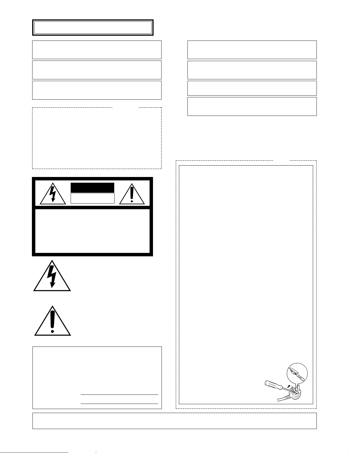
How to replace the fuse
Open the fuse compartment with
a screwdriver and replace the fuse
and fuse cover.
The serial number of this product may be found on the
bottom of the unit.
You should note the serial number of this unit in the
space provided and retain this book as a permanent
record of your purchase to aid identification in the event
of theft.
Model No.
Serial No.
THIS APPARATUS MUST BE EARTHED.
To ensure safe operation the three-pin plug supplied must be inserted only into a standard three-pin power point which is effectively
earthed through the normal household wiring. Extension cords used
with the equipment must be three-core and be correctly wired to provide connection to earth. Wrongly wired extension cords are a major
cause of fatalities.
The fact that the equipment operates satisfactorily does not imply
that the power point is earthed and that the installation is completely
safe. For your safety, if in any doubt about the effective earthing of
the power point, consult a qualified electrician.
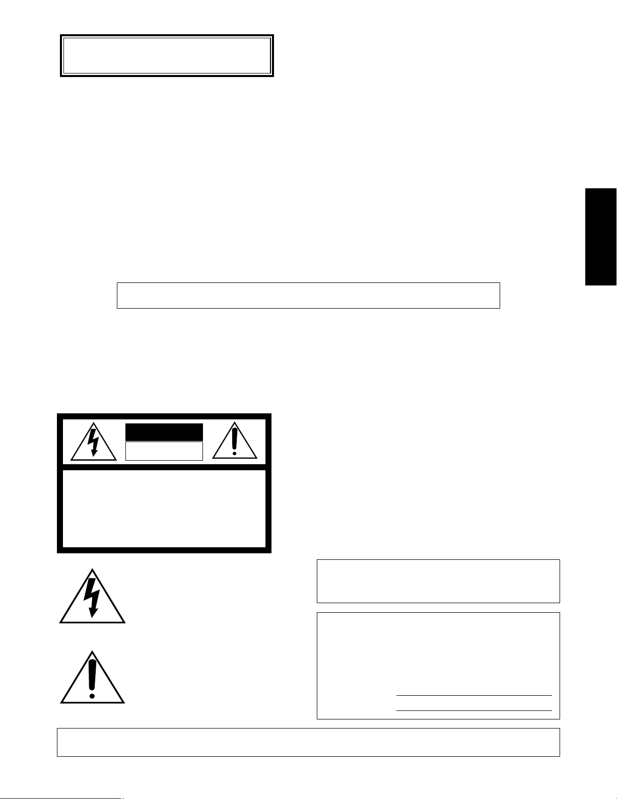
The lightning flash with arrowhead symbol, within an equilateral triangle, is
interned to alert the user to the presence
of uninsulated "dangerous voltage" within
the product's enclosure that may be of
sufficient magnitude to constitute a risk of
electric shock to persons.
The exclamation point within an equilateral triangle is intended to alert the user
to the presence of important operating
and maintenance (servicing) instructions
in the literature accompanying the appliance.
WARNING:
TO PREVENT FIRE OR SHOCK HAZARD, DO NOT EXPOSE THIS APPLIANCE TO RAIN OR MOISTURE.
CAUTION:
TO REDUCE THE RISK OF ELECTRIC SHOCK,
DO NOT REMOVE COVER (OR BACK), NO USER
SERVICEABLE PARTS INSIDE.
REFER SERVICING TO QUALIFIED SERVICE
PERSONNEL.
CAUTION
RISK OF ELECTRIC SHOCK
DO NOT OPEN
For U.K.
For Australia
ENGLISH VERSION
We declare under our sole responsibility that the product to which
this declaration relates is in conformity with the standards or other
normative documents following the provisions of Directive
EEC/89/336.
Dichiariamo sotto nostra esclusiva responsabilità che il prodotto a
cui si riferisce la presente dichiarazione è conforme agli standard o
altri documenti normativi ottemperanti alle disposizioni della direttiva
CEE/89/336.
Wij verklaren als enige aansprakelijke, dat het product waarop deze
verklaring betrekking heeft, voldoet aan de normen of andere normatieve documenten, overeenkomstig de bepalingen van Richtlijn
89/336/EEC.
Vi erklærer os eneansvarlige for, at dette produkt, som denne
deklaration omhandler, er i overensstemmelse med standarder eller
andre normative dokumenter i følge bestemmelserne i direktiv
89/336/EEC.
Vi deklarerar härmed värt fulla ansvar för att den produkt till vilken
denna deklaration hänvisar är i överensstämmelse med standarddokument, eller andra normativa dokument som framställs i EECdirektiv nr. 89/336.
Ilmoitamme yksinomaisella vastuullamme, että tuote, jota tämä
ilmoitus koskee, noudattaa seuraavia standardeja tai muita ohjeellisia asiakirjoja, jotka noudattavat direktiivin 89/336/EEC säädöksiä.
Vi erklærer oss alene ansvarlige for at produktet som denne
erklæringen gjelder for, er i overensstemmelse med følgende
normer eller andre normgivende dokumenter som følger bestemmelsene i direktiv 89/336/EEC.
Page 3

-1-
PREFACE
The WV-CM1430 is a colour monitor that ensure high-definition picture quality. All controls except for power are covered with a push door to give a sleek appearance on the
front. The main controls of Colour, Brightness, and
Contrast, are provided with sub controls to permit adjustment of preset levels. The ruggedly built metal cabinet is
rack-mountable using optional bracket WV-Q104.
Standard BNC-type input and output connectors enables
WV-CM1430 to be used with other CCTV monitors or
Panasonic video tape recorder.
FEATURES
• 37 cm (14") diagonal CRT size
(Approx. 13" diagonal actual visual size)
• Looping through BNC connectors for video input and
output with 75Ω auto termination
• Looping through RCA pin jack for audio input and output.
• Max. of 1.0W speaker output
• Selectable of A or B channel for input and output signals.
• Rack mountable using optional Rack Angle Bracket.
PRECAUTIONS
• Do not block the ventilation slots.
• Do place the video monitor at least 5cm (2”) apart from
the wall.
• Do not expose the monitor to water or moisture.
• Do not operate the monitor if it becomes wet.
• Do take immediate action if ever the monitor becomes
wet. Turn the power off and refer servicing to qualified
service personnel. Moisture can damage the monitor
and also create the danger of electric shock.
• Do not drop metallic parts in the slots. This action
could permanently damage the monitor. Turn the
power off immediately and refer servicing to qualified
service personnel.
• Do not attempt to disassemble the monitor. In order to
prevent electric shock, do not remove screws or cover.
There are no user-serviceable parts inside. Refer servicing to qualified service personnel.
• Do not operate the monitor beyond its temperature,
humidity or power source ratings.
Use the monitor under conditions where temperatures
are within −10°C - +50°C (14°F - 122°F), and humidity
is below 90%.
The input power source is 220 - 240V AC 50Hz.
CONTENTS
PREFACE .............................................................................................................................................................................................. 1
FEATURES ............................................................................................................................................................................................ 1
PRECAUTIONS ..................................................................................................................................................................................... 1
MAJOR OPERATING CONTROLS AND THEIR FUNCTIONS .............................................................................................................. 2
INSTALLATION ..................................................................................................................................................................................... 4
CABLE INFORMATION ........................................................................................................................................................................ 4
SYSTEM CONNECTIONS ..................................................................................................................................................................... 5
APPEARANCE ...................................................................................................................................................................................... 6
SPECIFICATIONS ................................................................................................................................................................................. 6
OPTIONAL ACCESSORY ..................................................................................................................................................................... 6
The model numbers listed in this Operating Instructions have no suffixed attached to it.
Page 4
-2-
Video Monitor WV-CM
1430
POWER
ON
OFF
AUDIOPICTURECONTRASTBRIGHTCOLOUR
A
B
V-HOLD
INPUT
SELECT
PUSH
FOCUS
OUT
VIDEOINAUDIO
IN
INPUT B
OUT OUT
VIDEOINAUDIO
IN
INPUT A
OUT
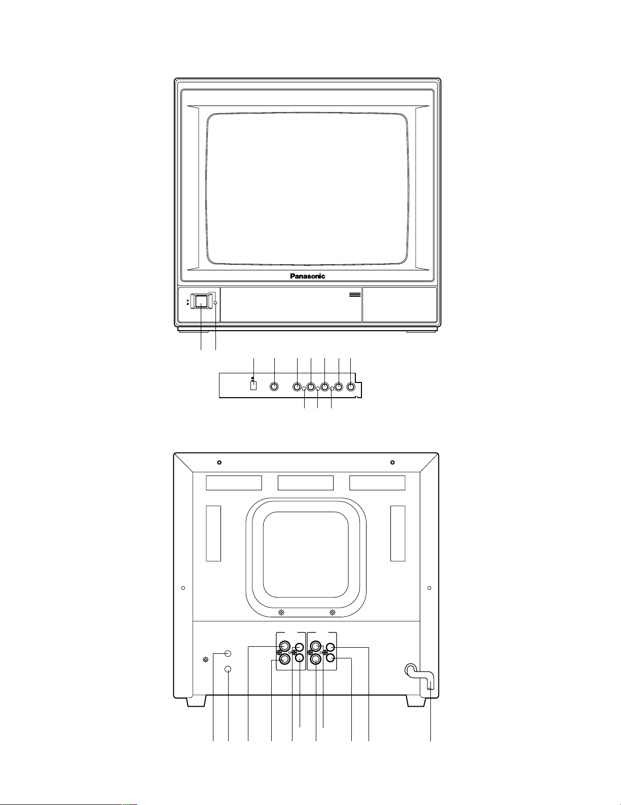
MAJOR OPERATING CONTROLS AND THEIR FUNCTIONS
qw
er tyuio
!0
!1 !2
@0 @1 @2 @3
!3
!4 !5 !6 !7
!8 !9
Page 5
-3-
1. Power Switch (POWER)
This is a push-push type switch which turns the power
of the monitor on and off.
Press once and the switch remains down (;) for turn-
ing on the power of monitor.
Press again, the switch comes up (l) for turning off
the power of the monitor.
2. Power Indicator
This indicator lights up when the monitor is turned on.
3. Input Selection Switch (INPUT SELECT A/B)
This is a push-push type switch which selects the signal input to A or B.
Press once and the switch remains down (;) for
selecting the INPUT B signal.
Press again, the switch comes up (l) for selecting
the INPUT A signal.
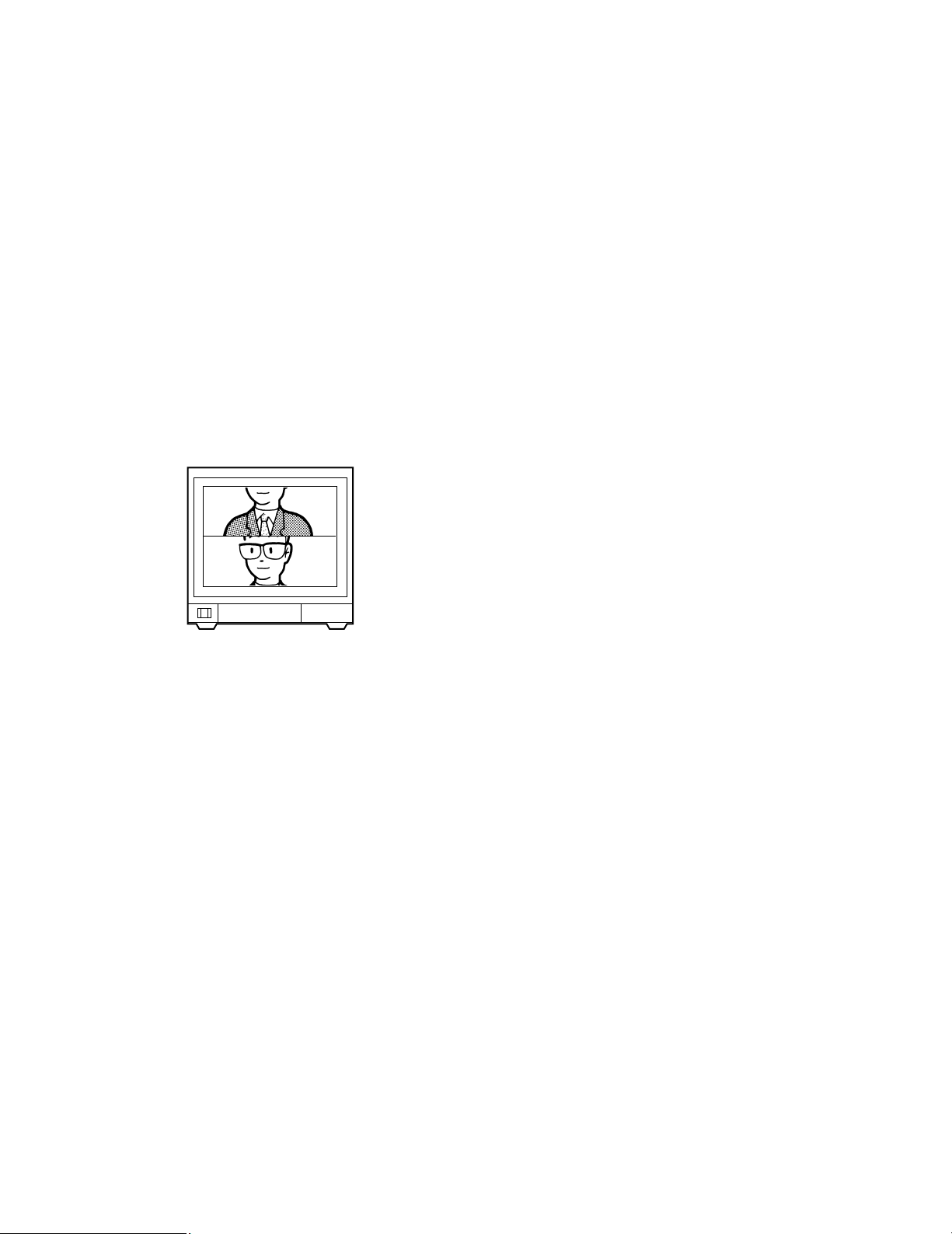
4. Vertical Hold Control (V-HOLD)
This control is used to adjust the picture in vertically.
12. Audio Volume (AUDIO)
Turn this volume clockwise to increase the audio level
and turn this volume counterclockwise to decrease the
audio level.
13. Focus Control (FOCUS)
This control is preset at the factory.
14. Screen Control
This control is preset at the factory. Do not adjust this
control. When the adjustment of this control is required,
refer to the qualified service personal.
15. Video Input Connector (INPUT B - VIDEO IN)
This input accepts a composite PAL video signal with
75Ω auto termination.
16. Video Output Connector (INPUT B - VIDEO OUT)
The video input signal connected to the Video Input
Connector (15) is looped through to this connector.
This connector becomes unterminated by connecting
a coaxial cable to it.
17. Audio Input Connector (INPUT B - AUDIO IN)
−8dB/Hi-Z audio signal can be supplied to this input
connector.
18. Audio Output Connector (INPUT B - AUDIO OUT)
The audio input signal connected to the Audio Input
Connector (17) is looped through to this connector.
19. Video Input Connector (INPUT A - VIDEO IN)
This input accepts a composite PAL video signal with
75Ω auto termination.
20. Video Output Connector (INPUT A - VIDEO OUT)
The video input signal connected to the Video Input
Connector (19) is looped through to this connector.
This connector becomes unterminated by connecting
a coaxial cable to it.
21. Audio Input Connector (INPUT A - AUDIO IN)
−8dB/Hi-Z audio signal can be supplied to this input
connector.
22. Audio Output Connector (INPUT A - AUDIO OUT)
The audio input signal connected to the Audio Input
Connector (21) is looped through to this connector.
23. Power Cord
5. Colour Control (COLOUR)
Turn this control clockwise to increase the picture's
colour and turn this control counterclockwise to
decrease the picture's colour.
6. Colour Subcontrol
This control is preset at the factory.
7. Bright Control (BRIGHT)
Turn this control clockwise to increase the picture's
brightness and turn this control counterclockwise to
decrease the picture's brightness.
8. Bright Subcontrol
This control is preset at the factory.
9. Contrast Control (CONTRAST)
Turn this control clockwise to increase the picture's
contrast and turn this control counterclockwise to
decrease the picture's contrast.
10. Contrast Subcontrol
This control is preset at the factory.
11. Picture Adjustment (PICTURE)
Turn this control clockwise for sharp picture and turn
this control counterclockwise for soft picture.
Page 6
-4-
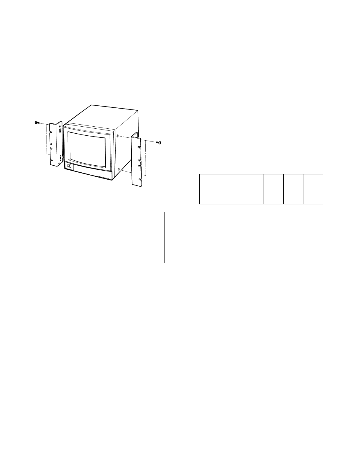
INSTALLATION
The Rack Angle Bracket WV-Q104 is provided for mounting
the Colour Video Monitor WV-CM1430 on the standard 19"
EIA rack.
(1) Remove four screws on both side of WV-CM1430.
These screws are no use after this.
(2) Fix the Rack Angle Bracket by using the supplied four
screws (M4 x 12).
(3) Mount the WV-CM1430 onto the rack by using the
eight screws (local procurement).
• Do not block the ventilation opening or slots on the
cover to prevent the monitor from rising temperature. Always keep the temperature in the rack within
50°C (122°F).
• Secure the rear of the monitor to the rack by using
the additional mounting angles (procured locally)
when the vibration is added to the rack.
Cautions
M4 x 12
(4 pcs.)
CABLE INFORMATION
Power Cable
1. Keep the Power Switch (1) in the OFF position during
installation.
2. Connect the Power Cord to a grounded electrical outlet.
Video Cable
1. Use 75-ohm coaxial cable. [RG-59/U (3C-2V), RG-6/U
(5C-2V), RG-11/U (7C-2V), RG-15/U (10C-2V)]
2. Up to 10 monitors can be hooked up in this configuration before signal loss occurs. Total cable length
should not exceed 150m (500 feet).
3. Wiring Precautions:
• Do not bend coaxial cable into a curve whose
radius is smaller than 10 times of its diameter:
• Never crush or pinch the cable.
All these will change the impedance of the cable and
cause poor picture quality.
Type of RG-59/U RG-6U RG-11/U RG-15/U
coaxial cable (3C-2V) (5C-2V) (7C-2V) (10C-2V)
Recommended (m) 250 500 600 800
maximum
cable length (ft) 825 1,650 1,980 2,640
Page 7
-5-
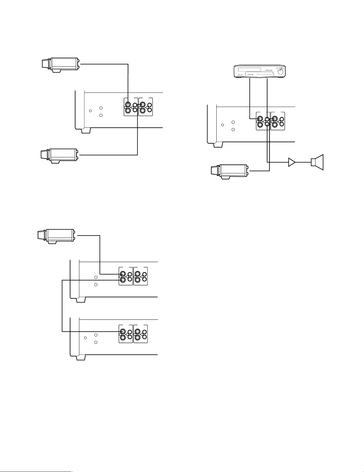
SYSTEM CONNECTIONS
1. Single monitor Connection
• Connect the Video Output terminal of the camera or
VTR to the Video Input Connector (15) or (19) of the
monitor with 75-ohm coaxial cable.
2. Multiple Monitor Connection
• Connect the Video Output terminal of the camera or
VTR to the Video Input Connector (15) or (19) of the
video monitor with 75-ohm coaxial cable.
• Connect the Video Output Connector (16) or (20) on
the first monitor to the Video Input Connector (15) or
(19) on the second monitor with 75-ohm coaxial cable,
and continue until all monitors are connected.
Note: Properly check the connections in the input and
output, because the monitor will not be properly
terminated if the connections are wrong.
3. Audio circuit signal
• Connect the Video Out Terminal of VTR or camera to
the Video Input Connector (15) or (19) of this monitor
with 75-ohm coaxial cable.
• Connect the Audio Out Terminal of VTR to the Audio
Input Connector (17) or (21) of this monitor and connect the Audio Input Terminal of the audio amplifier to
the Audio Output Connector (18) or (22) of this monitor
with a audio cable.
FOCUS
OUT
VIDEOINAUDIO
IN
INPUT B
OUT OUT
VIDEOINAUDIO
IN
INPUT A
OUT
FOCUS
OUT
VIDEOINAUDIO
IN
INPUT B
OUT OUT
VIDEOINAUDIO
IN
INPUT A
OUT
FOCUS
OUT
VIDEOINAUDIO
IN
INPUT B
OUT OUT
VIDEOINAUDIO
IN
INPUT A
OUT
FOCUS
OUT
VIDEOINAUDIO
IN
INPUT B
OUT OUT
VIDEOINAUDIO
IN
INPUT A
OUT
VIDEO OUT
Camera
Coax.
Cable
Coax.
Cable
VIDEO
OUT
Coax.
Cable
Coax.
Cable
VIDEO
OUT
VTR/Video Disc Player
Camera
Speaker
Amp
VIDEO
OUT
AUDIO
OUT
Camera
Page 8
-6-
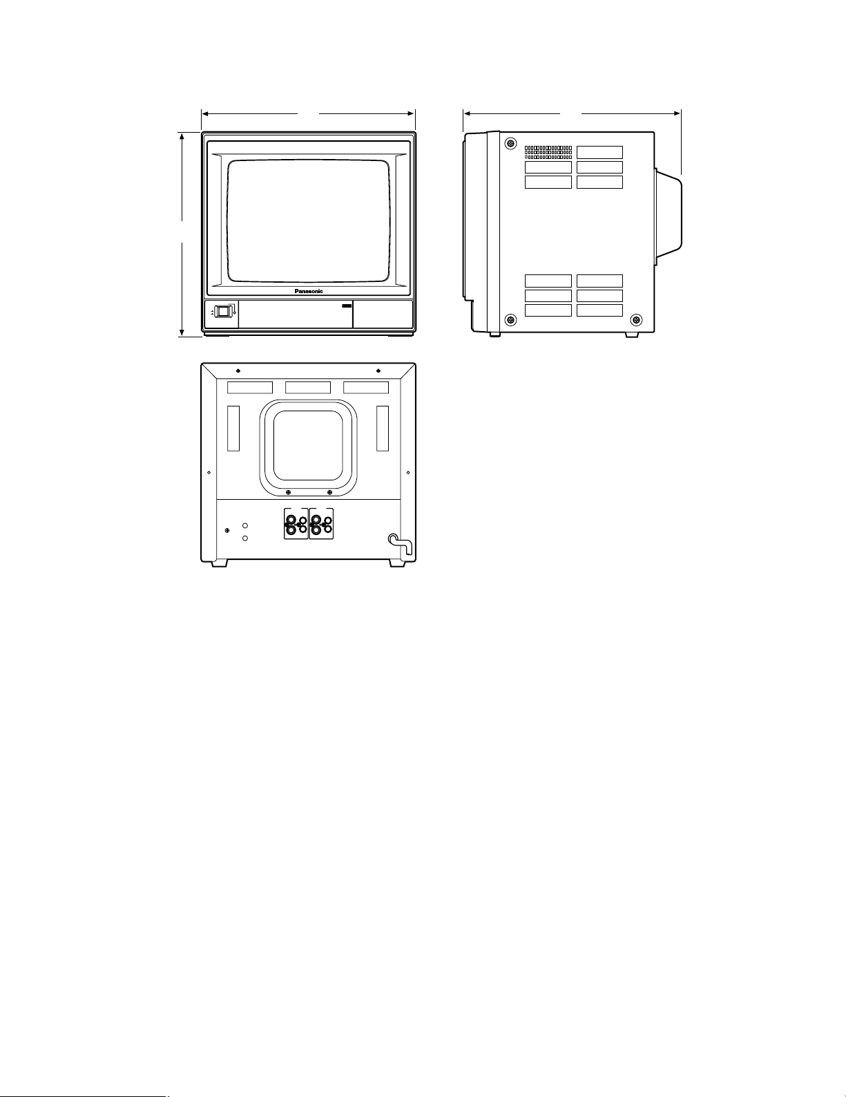
APPEARANCE
Unit: mm
SPECIFICATIONS
Power Source: WV-CM1430/A, WV-CM1430/B, WV-CM1430/G: 220 - 240V AC 50Hz
Power Consumption: Approx. 57 watts
Video Input/Output: 1.0 Vp-p composite/75Ω Auto Termination
Sweep Linearity: Less than 5%
Sweep Geometry: Less than 2%
Scanning Size: Approx. 8% (Overscanning)
CRT Size: 368.2 mm (14”) diagonal
Actual Visual Size: 335.4 mm (13”) diagonal
Audio Input/Output: −8dB/Hi-Z
Ambient Operating Temperature: −10°C - +50°C (14°F - 122°F)
Ambient Operating Humidity: Less than 90%
Dimensions: 370 (W) x 354 (H) x 371 (D) mm
Weight: 12.0kg
Weight and dimensions shown are approximate.
Specifications are subject to change without notice.
OPTIONAL ACCESSORY
Rack Angle Bracket .............................................. WV-Q104
Video Monitor WV-CM
1430
POWER
ON
OFF
PUSH
FOCUS
OUT
VIDEOINAUDIO
IN
INPUT B
OUT OUT
VIDEOINAUDIO
IN
INPUT A
OUT
371370
354
Page 9
-7-
INHALT
VORWORT ............................................................................................................................................................................................ 8
MERKMALE .......................................................................................................................................................................................... 8
VORSICHTSMAßNAHMEN ................................................................................................................................................................... 8
WICHTIGE BEDIENUNGSELEMENTE UND IHRE FUNKTIONEN ........................................................................................................ 9
EINBAU .............................................................................................................................................................................................. 11
KABEL-INFORMATIONEN .................................................................................................................................................................. 11
SYSTEMANSCHLÜSSE ...................................................................................................................................................................... 12
MAßZEICHNUNG ............................................................................................................................................................................... 13
TECHNFISCHE DATEN ...................................................................................................................................................................... 13
SONDERZUBEHÖR ............................................................................................................................................................................ 13
DEUTSCHE AUSGABE
(GERMAN VERSION)
Das Blitzzeichen mit Pfeil im gleichseitigen Dreieck soll den Benutzer auf das
Vorhandensein von nichtisolierter "gefährlicher Spannung" innerhalb des Gehäuses hinweisen, die so groß sein
kann, daß sie Gefahr eines elektrischen
Schlags darstellt.
Das Ausrufezeichen im gleichseitigen
Dreieck soll den Benutzer auf wichtige
Bedienungs- und Wartungsanweisungen in den Unterlagen hinweisen, die
dem Gerät beiliegen.
Die Fabriknummer dieses Gerätes ist auf dessen Bodenabdeckung angegeben.
Sie sollten die Fabriknummer dieses Gerätes in den dafür
vorgesehenen Raum eintragen und diese Anleitung als
Kaufsunterlage aufbewahren, um im Falle eines Diebstahls
die ldentifizierung zu erleichtern.
Modellnummer
Fabriknummer
WARNUNG: UM DIE GEFAHR VON BRAND ODER STROMSCHLAG ZU VERHÜTEN, DIESES GERÄT WEDER REGEN
NOCH FEUCHTIGKEIT AUSSETZEN.
WARNUNG:
WEDER DECKEL NOCH RÜCKPLATTE ABNEHMEN,
UM DIE GEFAHR EINES ELEKTRISCHEN SCHLAGS
ZU VERMEIDEN. DAS GERÄT ENTHÄLT KEINE
BAUTEILE, DIE VOM KUNDEN GEWARTET WERDEN
KÖNNEN.
CAUTION
RISK OF ELECTRIC SHOCK
DO NOT OPEN
Die in dieser Bedienungsanleitung aufgeführten Modellnummern weisen keinen Anhang auf.
DEUTSCH
HINWEIS:
Die in diesem Gerät entstehende Röntgenstrahlung ist
ausreichend abgeschirmt. Beschieunigungsspannung
mas. 25,5 kV.
Wir erklären in alleiniger Verantwortung, daß das Produkt, auf
das sich diese Erklärung bezieht, mit der folgenden Normen
oder normativen Dokumenten übereinstimmt.
Gemäß den Bestimmungen der Richtlinite 89/336/EEC.
Page 10

-8-
VORWORT
Bei dem Modell WV-CM1430 handelt es sich um einen
Farbmonitor mit hoher Auflösung und ausgezeichneter
Bildqualität. Alle Regler, ausgenommen Netzschalter, sind
mit einer Klappe abgedeckt,
wodurch die Frontseite schlank erscheint. Die Hauptregler
für Farbsättigung, Helligkeit und kontrast sind mit Hilfsregler versehen, die eine Einstellung der voreingestellten
Pegel gestatten. Das robuste Metallgehäuse kann unter
Verwendung der als Sonderzubehör erhältlichen Halterung
WV-Q104 in ein Rack eingebaut werden. Standard BNCEin- und -Ausgangsbuchsen gestatten die
Verwendung des Modells WV-CM1430 in Verbindung mit
anderen CCTV-Nonitoren oder Panasonic Videorecordern.
MERKMALE
• Bildschirmdiagonale 368,2 mm.
(Ungefähre Bilddiagonale 335,4 mm)
• Durchschleifen durch BNC-Steckverbinder für VideoEingang und -Ausgang mit automatischem Abschluß
von 75 Ohm.
• Durchschleifen durch Cinch-Buchsen für AudioEingang und -Ausgang
• Lautsprecher-Ausgangsleistung max. 1,0 W
• A- oder B-Kanal wählbar für Eingangs- und Ausgangssignale
• Rack-Einbau mit als Sonderzubehör erhältlichem RackEinbauwinkel.
VORSICHTSMAßNAHMEN
• Niemals die Belüftungsschlitze abdecken.
• Den Video-Monitor so aufstellen, daßein Abstand von
mindestens 50 mm zur Wand eingehalten wird.
• Den Monitor niemals Wasser oder Feuchtigkeit aussetzen.
• Den Monitor nicht einschalten, wenn dieser naßist.
• Falls der Monitor naßwird, sofort geeingnete
Gegenmanahmen treffen. Die Stromversorgung ausschalten und den Monitor von einem qualifizierten
Wartungstechniker überprüfen lassen.
Feuchtigkeit kann den Monitor beschädigen und zu
elektrischen Schlägen führen.
• Darauf achten, daßkeine Metallteile durch die
Belüftungsschlitze in das Innere des Gerätes kommen,
da sonst der Monitor permanent beschädigt werden
kann. Sofort die
Strombersorgung ausschalten und den Monitor von
einem qualifizierten Wartungstechniker überprüfen
lassen.
• Niemals den Monitor zu zerlegen versuchen.
Schrauben und Deckel dürfen nicht abgenommen werden, um elektrischen Schlägen vorzubeugen. Im
Inneren des Gerätes befinden sich keine vom
Anwender zu wartenden Teile. Wartungsarbeiten nur
von einem qualifizierten Wartungstechniker ausführen
lassen.
• Bei der Verwendung des Monitors immer die zulässige
Temperatur, Feuchtigkeit und Stromquelle einhalten.
Den Monitor nur im Temperaturbereich −10°C bis
+50°C und bei einer Luftfeuchtigkeit von weniger als
90% verwenden.
Die Stromversorgung muß 220 bis 240 V Wechselstrom, 50 Hz, betragen.
Page 11

-9-
Video Monitor WV-CM
1430
POWER
ON
OFF
AUDIOPICTURECONTRASTBRIGHTCOLOUR
A
B
V-HOLD
INPUT
SELECT
PUSH
FOCUS
OUT
VIDEOINAUDIO
IN
INPUT B
OUT OUT
VIDEOINAUDIO
IN
INPUT A
OUT
WICHTIGE BEDIENUNGSELEMENTE UND IHRE FUNKTIONEN
qw
er tyuio
!0
!1 !2
@0 @1 @2 @3
!3
!4 !5 !6 !7
!8 !9
Page 12

-10-
1. Netzschalter (POWER)
Dieser Drucktastenschalter dient für das Ein- und
Ausschalten der Stromversorgung des Monitors.
Die Taste einrasten (;), um die Stromversorgung
einzuschalten.
Die Taste durch nochmaliges Drücken wieder aus- rasten (l), um die Stromversorgung auszuschalten.
2. Netzstrom-Anzeige
Diese Anzeige leuchtet auf, wenn die Stromversorgung
des Monitors eingeschaltet ist.
3. Eingangs-Wahlschalter (INPUT SELECT A/B)
Dieser Drucktastenschalter wählt die Eingangssignale
A oder B an.
Die Taste einrasten (;), um das INPUT B Signal zu
wählen.
Die Taste durch nochmaliges Drücken wieder ausrasten (l), um das INPUT A Signal zu wählen.
4. Vertikaler Bildfang (V-HOLD)
Dieser Regler ist zu verwenden, um das vertikal durchlaufende Bild zu stabilisieren.
11. Bildeinstellung (PICTURE)
Diesen Regler für ein scharfes Bild im Uhrzeigersinn
bzw. für ein weiches Bild gegen den Uhrzeigersinn
drehen.
12. Audio-Lautstärke (AUDIO)
Diesen Regler im oder gegen den Uhrzeigersinn
drehen, um den Audio-Lautstärkepegel zu erhöhen
bzw. zu vermindern.
13. Fokussierregler (FOCUS)
Dieser Regler wurde im Werk voreingestellt.
14. Bildschirmregler
Dieser Regler wurde im Werk voreingestellt. Diesen
Regler nicht selbst einstellen. Falls eine Einstellung
dieses Reglers erforderlich ist, die Einstellung von
gualifiziertem Kundendienstpersonal ausführen lassen.
15. Video-Eingangsbuchse (INPUT B - VIDEO IN)
An diesen Eingang wird das PAL-Video-Kompositsignal mit automatischem Abschluß von 75 Ohm
angelegt.
16. Video-Ausgangsbuchse (INPUT B - VIDEO OUT)
Das an die Video-Eingangsbuchse (15) angeschlossene Video-Eingangssignal wird an diese Buchse
durchgeschleift.
Diese Buchse wird nicht abgeschlossen, wenn ein
Koaxialkabel angeschlossen wird.
17. Audio-Eingangsbuchse (INPUT B - AUDIO IN)
Ein −8 dB/Hi-Z Audiosignal kann an diese Eingangsbuchse angelegt werden.
18. Audio-Ausgangsbuchse (INPUT B - AUDIO OUT)
Das an die Audio-Eingangsbuchse (17) angeschlossene Audio-Eingangssignal wird an diese Buchse
durchgeschleift.
19. Video-Eingangsbuchse (INPUT A - VIDEO IN)
An diesen Eingang wird das PAL-Video-Kompositsignal mit automatischem Abschluß von 75 Ohm
angelegt.
20. Video-Ausgangsbuchse (INPUT A - VIDEO OUT)
Das an die Video-Eingangsbuchse (19) angeschlossene Video-Eingangssignal wird an diese Buchse
durchgeschleift.
Diese Buchse wird nicht abgeschlossen, wenn ein
Koaxialkabel angeschlossen wird.
21. Audio-Eingangsbuchse (INPUT A - AUDIO IN)
Ein −8 dB/Hi-Z Audiosignal kann an diese Eingangsbuchse angelegt werden.
22. Audio-Ausgangsbuchse (INPUT A - AUDIO OUT)
Das an die Audio-Eingangsbuchse (21) angeschlossene Audio-Eingangssignal wird an diese Buchse
durchgeschleift.
23. Netzkabel
5. Farbsättigungsregler (COLOUR)
Diesen Regler im oder gegen den Uhrzeigersinn
drehen, um die Farbsättigung zu erhöhen bzw. zu vermindern.
6. Farbsättigungs-Hilfsregler
Dieser Regler wurde im Werk voreingestellt.
7. Helligkeitsregler (BRIGHT)
Diesen Regler im oder gegen den Uhrzeigersinn
drehen, um den Bildhelligkeit zu erhöhen bzw. zu vermindern.
8. Helligkeits-Hilfsregler
Dieser Regler wurde im Werk voreingestellt.
9. Kontrastregler (CONTRAST)
Diesen Regler im oder gegen den Uhrzeigersinn
drehen, um den Bildkontrast zu erhöhen bzw. zu vermindern.
10. Kontrast-Hilfsregler
Dieser Regler wurde im Werk voreingestellt.
Page 13

-11-
EINBAU
Die Rack-Einbauwinkel WV-Q104 werden für den Einbau
des Video-Farbmonitors WV-CM1430 in ein EIA 19-Zoll
Standard-Rack mitgeliefert.
(1) Vier Schrauben von beiden Seiten des Monitors WV-
CM1430 abnehmen. Diese Schrauben werden danach
nicht mehr benötigt.
(2) Die Rack-Einbauwinkel mit Hilfe der vier mitgelieferten
Schrauben (M4 x 12) am Monitor anbringen.
(3) Den Monitor WV-CM1430 unter Verwendung von acht
Schrauben (örtlich beschafft) in das Rack einbauen.
• Die Belüftungsöffnungen oder -schlitze an der
Abdeckung nicht blockieren, um ein Ansteigen der
Temperatur im Monitor zu vermeiden. Immer darauf
achten, daß die Temperatur im Rack nicht mehr als
50°C beträgt.
• Die Rückseite des Monitors mit zusätzlichen
Einbauwinkeln (örtlich beschafft) am Rack sichern,
wenn das Rack Vibrationen ausgesetzt ist.
Vorsicht
M4 x 12
(4 Stück)
KABEL-INFORMATIONEN
Netzkabel
1. Den Netzschalter (1) auf die Position OFF einstellen,
während die Anschlüsse hergestellt werden.
2. Das Netzkabel an eine geerdete Netzsteckdose
anschließ en.
Video-Kabel
1. Nur 75-Ohm-Koaxialkabel [RG-59/U (3C-2V), RG-6/U
(5C-2V), RG-11/U (7C-2V), RG-15/U (10C-2V)] verwenden.
2. Bis zu 10 Monitore können in dieser Konfiguration
angeschlossen werden, bevor es zu Signalverlusten
kommt. Die gesamte Kabellänge sollte jedoch 150 m
nicht übersteigen.
3. Vorsichtsmaß nahmen bei der Verdrahtung:
• Beim Abbiegen eines Koaxialkabels muß der
Biegeradius mindestens dem 10-fachen Durchmesser entsprechen.
• Niemals ein Kabel plattdrücken oder einklemmen.
Durch diese Vorgänge wird die Impedanz des Kabels
geändert, was zu einer schlechten Bildqualität führt.
Typ des RG-59/U RG-6U RG-11/U RG-15/U
Koaxial-Kabels (3C-2V) (5C-2V) (7C-2V) (10C-2V)
Empfohlene
max. (m) 250 500 600 800
Kabellänge
Page 14

FOCUS
OUT
VIDEOINAUDIO
IN
INPUT B
OUT OUT
VIDEOINAUDIO
IN
INPUT A
OUT
FOCUS
OUT
VIDEOINAUDIO
IN
INPUT B
OUT OUT
VIDEOINAUDIO
IN
INPUT A
OUT
FOCUS
OUT
VIDEOINAUDIO
IN
INPUT B
OUT OUT
VIDEOINAUDIO
IN
INPUT A
OUT
FOCUS
OUT
VIDEOINAUDIO
IN
INPUT B
OUT OUT
VIDEOINAUDIO
IN
INPUT A
OUT
-12-
SYSTEMANSCHLÜSSE
1. Anschlußeines Monitors
• Die Video-Ausgangsbuchse der Kamera oder des
Videorecorders mit einem 75-Ohm Koaxial-Kabel mit
der Video-Eingangsbuchse (15) oder (19) des
Monitors verbinden.
2. Anschlußvon mehreren Monitoren
• Die Video-Ausgangsbuchse der Kamera oder des
Videorecorders mit einem 75-Ohm Koaxial-Kabel mit
der Video-Eingangsbuchse (15) oder (19) des
Monitores verbinden.
• Die Video-Ausgangsbuchse (16) oder (20) des ersten
Monitors mit einem 75-Ohm Koaxial-Kabel mit der
Video-Eingangsbuchse (15) oder (19) des zweiten
Monitors verbinden. Diese Anschlüsse sinngemäßeinhalten, bis alle Monitore verbunden sind.
Hinweis: Die Anschlüsse an den Eingangs- und
Ausgangsbuchsen richtig überprüfen, da der
Monitor nicht richtig abgeschlossen wird, wenn
die Anschlüsse falsch sind.
3. Audio-Schaltkreisignal
• Die Video-Ausgangsbuchse des Videorecorders oder
der Kamera mit einem 75-Ohm Koaxial-Kabel mit der
Video-Eingangsbuchse (15) oder (19) dieses Monitors
verbinden.
• Die Audio-Ausgangsbuchse des Videorecorders mit
einem 75-Ohm Koaxial-Kabel mit der Audio-Eingangsbuchse (17) oder (21) dieses Monitors und die AudioEingangsbuchse (18) oder (22) dieses Monitors
verbinden.
VIDEO OUT
Kamera
KoaxialKabel
VIDEO
OUT
VIDEO
OUT
Videorecorder/Video-Plattenspieler
Kamera
Lautsprecher
Verstärker
VIDEO
OUT
AUDIO
OUT
Kamera
KoaxialKabel
KoaxialKabel
KoaxialKabel
Page 15

-13-
MAßZEICHNUNG
Einheit: mm
TECHNISCHE DATEN
Stromquelle: WV-CM1430/A, WV-CM1430/B, WV-CM1430/G: 220 - 240 V Wechselstrom, 50 Hz
Leistungsaufnahme: Etwa 57 Watt
Video-Eingang/Ausgang: 1,0 Vs-s Komposit/automatischer Abschluß von 75 Ohm
Kipplinearität: Weniger als 5%
Kippgeometrie: Weniger als 2%
Überabtastung: Etwa 8%
Bildschirmdiagonale: 368,2 mm
Tatsächliche Bilddiagonale: 335,4 mm
Audio-Eingang/Ausgang: −8 dB/Hi-Z
Zulässige Betriebstemperatur: −10°C bis +50°C
Zulässige Luftfeuchtigkeit: Weniger als 90%
Abmessungen: 370 (B) x 354 (H) x 371 (T) mm
Gewicht: 12 kg
Gewicht und Abmessungen sind ungefähre Werte.
Änderungen der technischen Daten ohne Vorankündigung vorbehalten.
SONDERZUBEHÖR
Rack-Einbauwinkel ................................................ WV-Q104
Video Monitor WV-CM
1430
POWER
ON
OFF
PUSH
FOCUS
OUT
VIDEOINAUDIO
IN
INPUT B
OUT OUT
VIDEOINAUDIO
IN
INPUT A
OUT
371370
354
Page 16

-14-
TABLE DES MATIÈRES
PRÉFACE ............................................................................................................................................................................................ 15
CARACTÉRISTIQUES DOMINANTES ................................................................................................................................................ 15
MESURES DE PRÉCAUTION ............................................................................................................................................................. 15
PRINCIPAUX ORGANES DE RÉGLAGE ET LEURS FONCTIONS ..................................................................................................... 16
INSTALLATION ................................................................................................................................................................................... 18
RENSEIGNEMENTS RELATIFS AUX CÂBLES ................................................................................................................................... 18
RACCORDEMENT DE SYSTÈME ....................................................................................................................................................... 19
ASPECT EXTÉRIEUR .......................................................................................................................................................................... 20
CARACTERISTIQUES TECHNIQUES ................................................................................................................................................. 20
ACCESSOIRE OPTIONNEL ................................................................................................................................................................ 20
AVERTISSEMENT: NE JAMAIS EXPOSER CET APPAREIL À LA PLUIE NI LE LAISSER DANS UN LIEU HUMIDE
SOUS PEINE DE CRÉER UN AMORÇAGE ÉLECTRIQUE OU UNE ÉLECTROCUTION.
VERSION FRANÇAISE
(FRENCH VERSION)
L'éclair à extrémité fléchée placé dans
un triangle équilatéral est destiné à attirer l'attention de l'utilisateur sur la présence d'une "tension potentiellement
dangereuse" et non isolée se trouvant
dans les limites du coffret de l'appareil
dont la puissance est suffisante pour
constituer un risque important d'élec-trocution.
Le point d'exclamation placé dans un
triangle équilatéral sert à attirer l'attention de l'utilisateur sur des instructions
de fonctionnement et d'entretien (de
dépannage) à caractère important dans
la brochure qui accompagne l'appareil.
Le numéro de série de l'appareil se trouve sur la plaque de
fond.
Nous vous conseillons de relever le numéro de série de
votre appareil dans l'espace réservé ci-dessous et de conserver précieusement votre notice d'instructions en tant que
justificatif d'achat aux fins d'identification en cas de vol.
No. de modèle
No. de série
ATTENTION:
POUR ÉVITER TOUT RISQUE D'ÉLECTROCUTION,
LE COUVERCLE (OU LE PANNEAU ARRIÈRE)NE
DOIT JAMAIS ÊTRE DÉMONTÉ. AUCUNE PIÈCE
DESTINÉE À L'UTILISATEUR SE TROUVE À
L'INTÉRIEUR DE L'APPAREIL. CONFIER LES
RÉGLAGES ET LES RÉPARATIONS À UN DEPANNEUR PROFESSIONNEL.
CAUTION
RISK OF ELECTRIC SHOCK
DO NOT OPEN
Les numéros de modèle qui sont mentionnés dans les instructions d'utilisation n'ont aucune suffixe indiqué.
Nous déclarons sous notre seule responsabilitè que le produit
auquel se référe cette dèclaration est conforme à aux normes
ou autres documents normatif conformèment aux dispositions
de la Directive 89/336/CEE.
Page 17

-15-
PRÉFACE
Le modèle WV-CM1430 est un moniteur vidéo couleur à
haute rèsolution permettant d’obtenir des images d’excellente qualité. Toutes les commandes sont protégées par un
volet à l’exception de la touche d’alimentation afin de donner à la façade un aspect plus élégant. Les commandes
principales de réglage de couleur, luminosité et contraste
sont complétées de commandes secondaires qui permettent d’effectuer des réglages sur les niveaux préréglés. Le
robuste coffret métallique peut s’installer en rack quand il
est fait usage du rack standard optionnel WV-Q104. Les
connecteurs d’entrée et de sortie de type BNC standard
permettent au WV-CM1430 d’être utilisé avec d’autres
moniteurs vidéo de circuit fermé de télévision (CCTV) ou
avec un magnétoscope d’enregistrement Panasonic.
CARACTÉRISTIQUES DOMINANTES
• Tube à rayons cathodiaques de 368,2 mm (14 pouces)
en diagonal.
(Surface de visionnement réelle en diagonal de 335,4
mm (13 pouces) en diagonal)
• Connecteurs BNC de connexion en boucle pour des
entrées et sorties vidéo et terminaison automatique en
75 ohms.
• Bouclage réalisé par prise Cinch pour les entrées et
sorties son.
• Puissance maximum de 1,0 W pour la sortie haut-parler
• On peut commuter du canal A au canal B.
• Possibilité d’installation en rack avec cornière d'installation en bâti optionnel.
MESURES DE PRÉCAUTION
• Ne jamais obturer les fentes d’aération de l’appareil.
• Placer le moniteur vidéo à plus de 5 cm du mur.
• Ne jamais exposer le moniteur vidéo à la pluie ni le
soumettre à l’humidité.
• Le moniteur vidéo ne doit pas être mis en fonction s’il
est humide.
• Prendre immédiatement les mesures qui s’imposent si
le moniteur vidéo a été humidifié.
Couper tout d’abord l’alimentation et consulter un personnel qualifié. Non seulement l’humidité risque d’endommager le moniteur vidéo, mais ceci peut également être un risque d’électroction dans les pires cas.
• Ne laisser aucun objet métallique par les fentes
d’aération du moniteur vidéo. En effet, ceci risque
d’endommager le moniteur vidéo. Couper immédiatement l’alimentation et consulater un personnel qualifié.
• Ne jamais essayer de démonter le moniteur vidéo.
Pour éviter tout risque d’électrocution, ne jamais retirer
les vis de fixation ni les éléments du coffret. Aucun
composant destiné à l’utilisateur de l’appareil n’a été
placé à l’intérieur.
• Ne pas mettre le moniteur vidéo en service en dehors
des limites de température, d’humidité ou de puissance de courant d’alimentation.
Le moniteur vidéo doit être mis en service dans
deslimites de température ambiante se situant entre
−10°C et +50°C et un taux d'humidité inférieur à 90%.
Le courant d'alimentation secteur doit se trouver dans
les limites de 220 et 240V, à 50 Hz.
FRANÇAIS
Page 18

-16-
Video Monitor WV-CM
1430
POWER
ON
OFF
AUDIOPICTURECONTRASTBRIGHTCOLOUR
A
B
V-HOLD
INPUT
SELECT
PUSH
FOCUS
OUT
VIDEOINAUDIO
IN
INPUT B
OUT OUT
VIDEOINAUDIO
IN
INPUT A
OUT
PRINCIPAUX ORGANES DE RÉGLAGE ET LEURS FONCTIONS
qw
er tyuio
!0
!1 !2
@0 @1 @2 @3
!3
!4 !5 !6 !7
!8 !9
Page 19

-17-
1. Interrupteur d’alimentation (POWER)
Il s’agit d’un interrupteur poussoir qui permet de mettre
le moniteur vidéo sous tension et hors tension.
Appuyer une seule fois pour que l’interrupteur s’enclenche (;) et mette le moniteur vidéo sous tension.
Appuyer encore une fois pour débrayer l’interrupteur
(l) et coupe l’alimentation du moniteur vidéo.
2. Témoin d’alimentation
Lorsque le moniteur vidéo est mis sous tension, ce
témoin s'allume.
3. Sélecteur d’entrée (INPUT SELECT A/B)
Il s’agit d’un interrupteur poussoir qui permet de
sélectionner l’entrée A ou B.
Appuyer une seule fois pour que l’interrupteur s’enclenche (;) et sélectionne le signal d’entrée B.
Appuyer encore une fois pour débrayer l’interrupteur
(l) et sélectionner le signal d’entrée A.
4. Commande de réglage de stabilité verticale
(V-HOLD)
Cette commande de réglage est utilisée pour effectuer
un réglage de stabilité verticale de l'image.
11. Réglage de l’image (PICTURE)
Tourner le potentiomètre dans le sens des aiguilles
d’une montre pour rendre les images plus nettes et le
tourner dans le sens inverse pour atténuer les images.
12. Réglage volume (AUDIO)
Tourner cette commande de réglage de volume dans
le sens des aiguilles d'une montre pour augmenter le
niveau audio et la tourner dans le sens inverse des
aiguilles d'une montre pour le réduire.
13. Réglage de mise au point (FOCUS)
Ce réglage est préréglé en usine.
14. Réglage d’écran
Ce réglage est préréglé en usine.
Ne pas modifier le réglage de cette commande. Si
toutefois un réglage de cette commande s'avèrait
nécessaire, confier ce travail à un dépanneur qualifié.
15. Connecteur d’entrée vidéo (INPUT B - AUDIO IN)
Ce connecteur accepte un signal d'entrée vidéo PAL
composite à terminaison automatique de 75 ohms.
16. Connecteur de sortie vidéo (INPUT B - VIDEO OUT)
Le signal d’entrée vidéo qui est relié au connecteur
d’entrée vidéo (15) est bouclé par l’intermédiaire de ce
connecteur.
Ce connecteur n'est plus terminé quand un câble
coaxial lui est raccordé.
17. Connecteur d’entrée audio (INPUT B - AUDIO IN)
Un signal audio de −8 dB/Hi-Z peut être envoyé à ce
connecteur d’entrée.
18. Connecteur de sortie audio (INPUT B - AUDIO OUT)
Le signal d’entrée audio qui est relié au connecteur
d’entrée audio (17) est bouclé par l’intermédiaire de ce
connecteur.
19. Connecteur d’entrée vidéo (INPUT A - VIDEO IN)
Ce connecteur accepte un signal d'entrée vidéo PAL
composite à terminaison automatique de 75 ohms.
20. Connecteur de sortie vidéo (INPUT A - VIDEO OUT)
Le signal d’entrée vidéo qui est relié au connecteur
d’entrée vidéo (19) est bouclé par l’intermédiaire de ce
connecteur.
Ce connecteur n'est plus terminé quand un câble
coaxial lui est raccordé.
21. Connecteur d’entrée audio (INPUT A - AUDIO IN)
Un signal audio de −8 dB/Hi-Z peut être envoyé à ce
connecteur d’entrée.
22. Connecteur de sortie audio (INPUT A - AUDIO OUT)
Le signal d’entrée audio qui est relié au connecteur
d’entrée audio (21) est bouclé par l’intermédiaire de ce
connecteur.
23. Cordon d’alimentation
5. Réglage de couleur (COLOUR)
Tourner cette commande dans le sens des aiguilles
d'une montre pour accentuer la couleur et la tourner
dans le sens inverse des aiguilles d'une montre pour
atténuer la couleur de l'image.
6. Réglage secondaire de couleur
Ce réglage est préréglé en usine.
7. Réglage de luminosité
Tourner cette commande dans le sens des aiguilles
d'une montre pour accentuer la luminosité des images
et la tourner dans le sens inverse des aiguilles d'une
montre pour l'atténuer.
8. Réglage secondaire de luminosité (BRIGHT)
Ce réglage est préréglé en usine.
9. Réglage de contraste (CONTRAST)
Tourner cette commande dans le sens des aiguilles
d'une montre pour accentuer le contraste des images
et la tourner dans le sens inverse des aiguilles d'une
montre pour l'atténuer.
10. Réglage secondaire de contraste
Ce réglage est préréglé en usine.
Page 20

-18-
INSTALLATION
La cornière d'installation en bâti de 19 pouces aux normes
EIA WV-Q104 doit être utilisée pour effectuer l'installation
du moniteur vidéo couleur WV-CM1430.
(1) Retirer les quatre vis de fixation des flancs du moniteur
vidéo WV-CM1430. Ces vis de fixation ne sont pas
réutilisées ultérieurement.
(2) Installer les cornières d'installation en bâti en utilisant
les quatre vis de fixation qui sont fournies (M4 x 12).
(3) Installer le moniteur vidéo WV-CM1430 dans le bâti en
utilisant les huit vis de fixation (à se procurer localement).
• Ne pas obturer les ouvertures ni les fentes
d'aération du couvercle car ceci aurait pour effet de
provoquer un accroisseement de la température
interune. La température intérieure du bâti doit être
maintenue à moins de 50°C.
• Immobiliser l'arrière du moniteur vidéo en installant
des cornières supplémentaires (à se procurer
localement) si le bâti subit des vibrations.
Attention
M4 x 12
(4 él)
RENSEIGNEMENTS RELATIFS AUX CÂBLES
Cordon d’alimentation
1. Conserver l’interrupteur d’alimentation (1) en position
OFF pendant la durée de l’installation.
2. Raccorder le cordon d’alimentation à une prise de
sortie secteur reliée à la terre.
Câble vidéo
1. Se servir d’un câble coaxial de 75 ohms [RG-59/U
(3C-2V), RG-6/U (5C-2V), RG-11/U (7C-2V), RG-15/U
(10C-2V)]
2. Un nombre maximum de 10 moniteurs vidéo peut être
utilisé avec cette configuration avant qu’une perte de
signal se produise. La longueur totale du câble ne doit
pas dépasser 150 m.
3. Mesures de précaution à prendre avec les câbles:
• Ne jamais former de courbure avec les câbles ni
former de boucle dont le rayon est inférieur à 10
fois son diamètre.
• Ne jamais écraser ni pincer le câble.
Toutes ces conditions font varier l’impédance du
câble et affecte la qualité des images.
Type de RG-59/U RG-6U RG-11/U RG-15/U
câble coaxial (3C-2V) (5C-2V) (7C-2V) (10C-2V)
Longueur (m) 250 500 600 800
maximum
recommandée (ft) 825 1 650 1 980 2 640
Page 21

FOCUS
OUT
VIDEOINAUDIO
IN
INPUT B
OUT OUT
VIDEOINAUDIO
IN
INPUT A
OUT
FOCUS
OUT
VIDEOINAUDIO
IN
INPUT B
OUT OUT
VIDEOINAUDIO
IN
INPUT A
OUT
FOCUS
OUT
VIDEOINAUDIO
IN
INPUT B
OUT OUT
VIDEOINAUDIO
IN
INPUT A
OUT
FOCUS
OUT
VIDEOINAUDIO
IN
INPUT B
OUT OUT
VIDEOINAUDIO
IN
INPUT A
OUT
-19-
RACCORDEMENT DE SYSTÈME
1. Branchement d’un seul moniteur vidéo
• Raccorder la prise de sortie vidéo de la caméra vidéo
ou du magnétoscope au connecteur d’entrée vidéo
(15) ou (19) du moniteur vidéo avec un câble coaxial
de 75 ohms.
2. Branchement de plusieurs moniteurs vidéo
• Raccorder la prise de sortie vidéo de la caméra vidéo
ou du magnétoscope au connecteur d’entrée vidéo
(15) ou (19) du moniteur vidéo avec un câble coaxial
de 75 ohms.
• Raccorder le connecteur de sortie vidéo (16) ou (20)
du premier moniteur vidéo au connecteur d’entrée
vidéo (15) ou (19) du deuxième moniteur vidéo avec
un câble coaxial de 75 ohms et continuer ainsi jusqu’à
ce que tous les moniteurs vidéo soient raccordés.
3. Signal de circuit audio
• Raccorder la prise de sortie vidéo du magnétoscope
ou de la caméra vidéo au connecteur d’entrée vidéo
(15) ou (19) du moniteur vidéo avec un câble coaxial
de 75 ohms.
• Raccorder la prise de sortie audio du magnétoscope
au connecteur d’entrée audio (17) ou (21) du moniteur
vidéo avec un câble cinch et relier la prise d’entrée
audio de l’amplificateur audio au connecteur de sortie
audio (18) ou (22) du moniteur vidéo avec un câble
cinch.
VIDEO OUT
Caméra
Câble
coaxial
VIDEO
OUT
VIDEO
OUT
Magnétoscope/lecteur de vidéodisque
Caméra
Haut-parleur
Amplificateur
VIDEO
OUT
AUDIO
OUT
Caméra
Câble
coaxial
Câble
coaxial
Câble
coaxial
Remarque: Vérifier minutieusement les raccordements
des entrées et des sorties parce que la terminaison ne sera pas réalisée correctement si les
branchements sont mal faits.
Page 22

-20-
ASPECT EXTÉRIEUR
Unité: mm
CARACTERISTIQUES TECHNIQUES
Source d’alimentation: WV-CM1430/A, WV-CM1430/B, WV-CM1430/G: 220 - 240 V CA, 50 Hz
Puissance consommée: Environ 57 watts
Entrée/sortie vidéo: Signal composite de 1,0 Vcc/terminaison automatique en 75 ohms
Linéarité de balayage: Moins de 5 %
Géométrie de balayage: Moins de 2 %
Balayage: Surbalayage (Environ 8 %)
Taille du tube à rayons cathodiques: 368,2 mm (14 pouces) en diagonal
Taille de la surface de visionnement réelle: 335,4 mm (13 pouces) en diagonal
Entrée/sortie audio: −8 dB/Hi-Z
Température de fonctionnement: −10°C à +50°C
Humidité ambiante: Moins de 90 %
Dimensions: 370 (L) x 354 (H) x 371 (P) mm
Poids: 12 kg
Le poids et les dimensions sont approximatifs.
Sous réserve de modification des renseignements techniques à des fins d’amélioration sans préavis.
ACCESSOIRE OPTIONNEL
Cornière de fixation en bâti ................................... WV-Q104
Video Monitor WV-CM
1430
POWER
ON
OFF
PUSH
FOCUS
OUT
VIDEOINAUDIO
IN
INPUT B
OUT OUT
VIDEOINAUDIO
IN
INPUT A
OUT
371370
354
Page 23

-21-
ATENCION: PARA EVITAR INCENDIOS O EL PELIGRO DE SACUDIDA ELÉCTRICA, NO EXPONGA ESTE APARATO A
LA LLUVIA NI A LA HUMEDAD.
EI símbolo del relámpago con cabeza de
flecha, dentro de un triángulo equilátero,
tiene la función de llamar la atención del
usuario a la presencia de "tensión peligrosa" no aislada dentro de la caja del
producto que puede ser de intensidad
suficiente para constituir un riesgo de
sacudidas eléctricas a las personas.
EI símbolo del punto de exclamación
dentro de un triángulo equilátero tiene la
función de llamar la atención del usuario
a la presencia de importantes instrucciones de mantenimiento (servicio) en la
literatura que acompaña el equipo.
EI número de serie de este producto está estampado en la
tapa inferior del aparato.
Asegúrese de apuntar el número de serie de este aparato
en el blanco señalado y de guardar este manual de instrucciones como un registro permanente de su compra para
ayudar la identificación en el caso de robo.
N° de modelo
N° de serie
VERSION ESPAÑOLA
(SPANISH VERSION)
Los números de modelo enumerados en este manual de instrucciones no tienen sufijos adicionados.
CAUTION
RISK OF ELECTRIC SHOCK
DO NOT OPEN
ATENCION:
PARA REDUCIR EL RIESGO DE SACUDIDAS ELECTRICAS, NO QUITE LA TAPA SUPERIOR
(OTRASERA). NO HAY NINGUNA PIEZA SUSCEPTIBLE A MANTENIMIENTO POR EL USUARIO.
SOLICITE LOS SERVICIOS TECNICOS A PERSONAL CUALIFICADO.
ESPAÑOL
INDICE
PREFACIO .......................................................................................................................................................................................... 22
CARACTERISTICAS ........................................................................................................................................................................... 22
PRECAUCIONES ................................................................................................................................................................................ 22
CONTROLES PRINCIPALES DE OPERACION Y SUS FUNCIONES .................................................................................................. 23
INSTALACION .................................................................................................................................................................................... 25
INFORMACION DE CABLES .............................................................................................................................................................. 25
CONEXIONES DEL SISTEMA ............................................................................................................................................................. 26
ASPECTO EXTERIOR ......................................................................................................................................................................... 27
ESPECIFICACIONES .......................................................................................................................................................................... 27
ACCESORIOS OPCIONALES ............................................................................................................................................................. 27
Nosotros declaramos bajo nuestra ùnica responsabilidad
que el producto a que hace referencia esta declaraciòn
està conforme con las normas u otros documentos normativos siguiendo las estipulaciones de la directiva
CEE/89/336.
Page 24

-22-
PREFACIO
El WV-CM1430 es un monitor en colour de alta definición
que asegura una calida de imagen de muy buena definición. Todos los controles, excepto el de la alimentación,
están cubierta con una puerta tipo presión para proporcionar un aspecto exterior elegante en la parte frontal. Los
controles principales del colour, brillo, y contraste están
provistos de controles secundarios para permitir el ajuste
de los niveles preajustados. El exterior metálico de gran
resistencia puede montarse en un bastidor usando la
ménsula opcional WV-Q104. Los conectores de entrada y
salida tipo BNC estándar permiten utilizar el WV-CM1430
con otros monitores CCTV o una videograbadora
Panasonic.
CARACTERISTICAS
• Tamaño del tubo de rayos catódicos de 37 cm (14") en
diagonal.
(Aprox. 13” de tamaño de visión real en diagonal)
• Bucle mediante conectores BNC para entrada y salida
de vídeo con terminación automática de 75Ω
• Bucle mediante clavija RCA para entrada y salida de
audio
• Máx. 1,0W para salida de altavoz
• Canal A o B seleccionable para señales de entrada y
salida
• Pueden montarse en un bastidor usando la ménsula
angular para bastidor opcional
PRECAUCIONES
• No bloquee las ranuras de ventilación.
• Coloque el monitor de vídeo por lo menos a 5 cm de la
pared.
• No exponga el motor al agua ni a la humedad.
• No ponga en funcionamiento el motor si se ha mojado.
• Tome una acción inmediatamente con el monitor en
caso de mojarse. Desconecte la alimentación y llévelo
a un centro de servicio técnico cualificado. La
humedad puede dañar el monitor y crear el peligro de
descargas eléctricas.
• No deje caer objetos metálicos por las ranuras, porque
podría dejar dañado permanentemente el monitor.
Desconecte inmediatamente la alimentación y llévelo a
un centro de servicio técnico cualificado.
• No intente desmontar el monitor. Con el fin de evitar
descargas eléctricas, no extraiga los tornillos i la
cubierta. No hay partes en el interior que pueda
reparar el usuario. Llévelo a un centro de servicio
técnico cualificado.
• No opere el monitor fuera de sus límites de temperatura, humedad y de alimentación.
Opere el monitor bajo condiciones en las que las temperaturas estén dentro de −10°C a +50°C y la
humedad sea de menos del 90%.
La alimentación de entrada es de 220-240V CA, 50 Hz.
Page 25

-23-
Video Monitor WV-CM
1430
POWER
ON
OFF
AUDIOPICTURECONTRASTBRIGHTCOLOUR
A
B
V-HOLD
INPUT
SELECT
PUSH
FOCUS
OUT
VIDEOINAUDIO
IN
INPUT B
OUT OUT
VIDEOINAUDIO
IN
INPUT A
OUT
CONTROLES PRINCIPALES DE OPERACION Y SUS FUNCIONES
qw
er tyuio
!0
!1 !2
@0 @1 @2 @3
!3
!4 !5 !6 !7
!8 !9
Page 26

-24-
1. Interruptor de la alimentación (POWER)
Es un interruptor del tipo presión que conecta y
desconecta la alimentación del monitor.
Presiónelo una vez de modo que quede presionado
(;) para conectar la alimentación del monitor.
Presiónelo de nuevo, de modo que quede salido (l)
para desconectar la alimentación del monitor.
2. Indicador de la alimentación
Este indicador se enciende cuando se conecta la alimentación del monitor.
3. Selector de entrada (INPUT SELECT A/B)
Es un selector tipo presión que selecciona la entrada
de señal a A o B.
Presiónelo una vez y quedará presionado (;) para
seleccionar la señal de INPUT B.
Presiónelo de nuevo, de modo que quede salido (l)
para seleccionar la señal de INPUT A.
4. Control de retención vertical (V-HOLD)
Este control se usa para ajustar verticalmente la imagen.
11. Ajuste de la imagen (PICTURE)
Gire este control hacia la derecha para aumentar la
nitidez de la imagen, y gírelo hacia la izquierda para
reducir la nitidez de la imagen.
12. Volumen del sonido (AUDIO)
Gire este control hacia la derecha para aumentar el
nivel de sonido, y gírelo hacia la izquierda para reducir
el nivel de sonido.
13. Control del enfoque (FOCUS)
Este control está preajustado en fábrica.
14. Este control está preajustado en fábrica.
No lo ajuste. Cuando se requiere el ajuste de este control, consulte a personal de servicio técnico cualificado.
15. Conector de entrada de vídeo
(INPUT B - VIDEO IN)
Esta entrada acepta una señal de vídeo PAL compuesta con terminación automática de 75Í.
16. Conector de salida de vídeo (INPUT B - VIDEO OUT)
La señal de vídeo conectada al conector de entrada
de vídeo (15) se pone en bucle mediante este conector.
Este conector pasa a quedar sin terminar conectándole un cable coaxial.
17. Conector de entrada de audio (INPUT B - AUDIO IN)
Puede suministrarse a este conector de entrada una
señal de audio de −8 dB/Hi-Z.
18. Conector de salida de audio
(INPUT B - AUDIO OUT)
La señal de audio conectada al conector de entrada
de audio (17) se pone en bucle mediante este conector.
19. Conector de entrada de vídeo
(INPUT A - VIDEO IN)
Esta entrada acepta una señal de vídeo PAL compuesta con terminación automática de 75Í.
20. Conector de salida de vídeo (INPUT A - VIDEO OUT)
La señal de vídeo conectada al conector de entrada
de vídeo (19) se pone en bucle mediante este conector.
Este conector pasa a quedar sin terminar conectándole un cable coaxial.
21. Conector de entrada de audio (INPUT A - AUDIO IN)
Puede suministrarse a este conector de entrada una
señal de audio de −8 dB/Hi-Z.
22. Conector de salida de audio
(INPUT A - AUDIO OUT)
La señal de audio conectada al conector de entrada
de audio (21) se pone en bucle mediante este conector.
23. Cable de la alimentación
5. Control del colour (COLOUR)
Gire este control hacia la derecha para aumentar el
colour de la imagen, y gírelo hacia la izquierda para
reducir el colour de la imagen.
6. Control secundario del colour
Este control está preajustado en fábrica.
7. Control del brillo (BRIGHT)
Gire este control hacia la derecha para aumentar el
brillo de la imagen, y gírelo hacia la izquierda para
reducir el brillo de la imagen.
8. Control secundario del brillo
Este control está preajustado en fábrica.
9. Control del contraste (CONTRAST)
Gire este control hacia la derecha para aumentar el
contraste de la imagen, y gírelo hacia la izquierda para
reducir el contraste de la imagen.
10. Control secundario del contraste
Este control está preajustado en fábrica.
Page 27

-25-
INSTALACION
La ménsula angular para bastidor WV-Q104 se suministra
para montar el monitor de vídeo en colour WV-CM1430 al
bastidor EIA de 19” estándar.
(1) Extraiga los cuatro tornillos de ambos lados del WV-
CM1430. Estos tornillos no se usan después.
(2) Fije la ménsula angular para bastidor usando los cua-
tro tornillos suministrados (M4 x 12).
(3) Monte el WV-CM1430 en el bastidor usando los ocho
tornillos (de venta local).
• No bloquee las aberturas ni ranuras de ventilación
de la cubierta para evitar que aumente la temperatura del monitor. Mantenga siempre la temperatura del bastidor dentro de 50°C.
• Fije la parte posterior del monitor al bastidor usando los ángulos de montaje adicionales (de venta
local) cuando se producen vibraciones en el bastidor.
Precauciones
M4 x 12
(4 pcs.)
INFORMACION DE CABLES
Cable de la alimentación
1. Mantenga el interruptor de la alimentación (1) en la
posición OFF durante la instalación.
2. Conecte el cable de alimentación a una toma de corriente con toma de tierra.
Cable de vídeo
1. Emplee cable coaxial de 75 ohmios [RG-59/U (3C-2V),
RG-6/U (5C-2V), RG-11/U (7C-2V), RG-15/U (10C-2V)].
2. Pueden conectarse hasta 10 monitores en esta configuración antes de ocurrir la pérdida de la señal. La longitud total del cable no debe exceder de 150 m.
3. Precauciones para las conexiones:
• No doble el cable coaxial en una curva cuyo radio
sea menos de 10 veces su diámetro.
• No prense ni pellizque el cable.
Todo esto cambiaría la impedancia del cable y
causaría mala calidad de imagen.
Tipo de RG-59/U RG-6U RG-11/U RG-15/U
cable coaxial (3C-2V) (5C-2V) (7C-2V) (10C-2V)
Longitud máxima (m) 250 500 600 800
del cable
recomendada (ft) 825 1 650 1 980 2 640
Page 28

FOCUS
OUT
VIDEOINAUDIO
IN
INPUT B
OUT OUT
VIDEOINAUDIO
IN
INPUT A
OUT
FOCUS
OUT
VIDEOINAUDIO
IN
INPUT B
OUT OUT
VIDEOINAUDIO
IN
INPUT A
OUT
FOCUS
OUT
VIDEOINAUDIO
IN
INPUT B
OUT OUT
VIDEOINAUDIO
IN
INPUT A
OUT
• Conecte el terminal de salida de vídeo de la cámera o
vídeo al conector de entrada de vídeo (15) o (19) del
monitor usando cable coaxial de 75 ohmios.
• Conecte el terminal de salida de audio del vídeo al
conector de entrada de audio (17) o (21) de este monitor y conecte el terminal de entrada de audio del
amplificador de audio al conector de salida de audio
(18) o (22) de este monitor usando cable de audio.
FOCUS
OUT
VIDEOINAUDIO
IN
INPUT B
OUT OUT
VIDEOINAUDIO
IN
INPUT A
OUT
-26-
CONEXIONES DEL SISTEMA
1. Conexión de un solo monitor
• Conecte el terminal de salida de vídeo de la cámara o
vídeo al conector de entrada de vídeo (15) o (19) del
monitor usando cable coaxial de 75 ohmios.
2. Conexión de varios monitores
• Conecte el terminal de salida de vídeo de la cámara o
vídeo al conector de entrada de vídeo (15) o (19) del
monitor usando cable coaxial de 75 ohmios.
• Conecte el conector de salida de vídeo (16) o (20) del
primer monitor del conector de entrada de vídeo (15) o
(19) del segundo monitor usando cable coaxial de 75
ohmios, y continúe hasta que se hayan conectado
todos los monitores.
Nota: Compruebe si las conexiones de entada y de
salida son correctas, porque el monitor no estará
correctamente terminado si las conexiones son
erróneas.
3. Señal del circuito de audio
VIDEO OUT
Cámara
Cable
coaxial
Cable
coaxial
VIDEO
OUT
Cable
coaxial
Cable
coaxial
VIDEO
OUT
Vídeo/reproductor de videodiscos
Cámara
Altavoz
Amplificador
VIDEO
OUT
AUDIO
OUT
Cámara
Page 29

-27-
ASPECTO EXTERIOR
Unidad: mm
ESPECIFICACIONES
Alimentación: WV-CM1430/A,, WV-CM1430/B, WV-CM1430/G: 220 - 240V CA, 50 Hz
Consumo de energía: Aprox. 57 vatios
Entrada/salida de vídeo: 1,0 Vp-p compuesta/terminacción automática de 75Ω
Linealidad de barrido: Menos del 5%
Geometría de barrido: Menos del 2%
Tamaño de exploración: Aprox. el 8% (sobreexploración)
Tamaño del tubo de rayos catódicos: 368,2 mm (14”) en diagonal
Tamaño de imagen real: 335,4 mm (13”) en diagonal
Entrada/salida de audio: −8 dB/Hi-Z
Temperatura ambiental de operación: −10°C - +50°C
Humedad ambiental de operación: Menos del 90%
Dimensiones: 370 (An) x 354 (Al) x 371 (Prf) mm
Peso: 12,0 kg
El peso y las diensiones mostradas son aproximados.
Especificaciones sujetas a cambios sin previo aviso.
ACCESORIOS OPCIONALES
Ménsula angular para bastidor ............................. WV-Q104
Video Monitor WV-CM
1430
POWER
ON
OFF
PUSH
FOCUS
OUT
VIDEOINAUDIO
IN
INPUT B
OUT OUT
VIDEOINAUDIO
IN
INPUT A
OUT
371370
354
Page 30

Matsushita Electric Industrial Co., Ltd.
Central P.O. Box 288, Osaka 530-91, Japan
N0495-1125 YWV8QA4034CN Printed in Japan
N 19 Gedruckt in Japan
Imprimé au Japon
Impreso en Japón
 Loading...