

Page 1

ctions
Color Monitor
WV-CM143
Page 2
CONTENTS
PREFACE............................................................................................................................................................................................. 1
FEATURES........................................................................................................................................................................................... 1
PRECAUTIONS.................................................................................................................................................................................... 1
MAJOR OPERATING CONTROLS AND THEIR FUNCTIONS ........................................................................................................... 2
OPERATING PROCEDURES .............................................................................................................................................................. 5
SETUP OPERATION ........................................................................................................................................................................... 9
CONNECTIONS.................................................................................................................................................................................. 12
SYSTEM CONNECTION .................................................................................................................................................................... 16
SPECIFICATIONS ............................................................................................................................................................................. 18
CAUTION:
Before attempting to connect or operate this product,
please read the label on the bottom.
CAUTION
RISK OF ELECTRIC SHOCK
CAUTION;
TO REDUCE THE RISK OF ELECTRIC SHOCK, DO
NOT REMOVE COVER (OR BACK). NO USER SER
VICEABLE PARTS INSIDE.
REFER SERVICING TO QUALIFIED SERVICE PER
SONNEL.
The lightning flash with arrowhead sym
bol, within an equilateral triangle, is
intended to alert the user to the pres
ence of uninsulated "dangerous voltage"
A
SA 1965
SA 1966
within the product's enclosure that may
be of sufficient magnitude to constitute a
risk of electric shock to persons.
The exclamation point within an equilat
eral triangle is intended to alert the user
to the presence of important operating
and maintenance (servicing) instructions
in the literature accompanying the appli
ance.
-------------------------------------------------------------------------------------For U.S.A --I
Warning:
This equipment generates and uses radio frequency ener
gy and if not installed and used properly, i.e., in strict
accordance with the instruction manual, may cause harmful
interference to radio communications. It has been tested
and found to comply with the limits for a Class A computing
device pursuant to Subpart J of Part 15 of FCC Rules,
which are designed to provide reasonable protection
against such interference when operated in a commercial
environment.
The serial number of this product may be found on the bot
tom of the unit.
You should note the serial number of this unit in the space
provided and retain this book as a permanent record of your
purchase to aid identification in the event of theft.
Model No.
Serial No.______________________________________
_____________________________________
WARNING:
TO PREVENT FIRE OR SHOCK HAZARD, DO NOT EXPOSE THIS APPLIANCE TO RAIN OR MOISTURE.
Page 3

PREFACE
The Panasonic's WV-CI\/1143 Color Monitor is designed for
use with the specified Color CCTV Camera.
Up to four cameras can be connected with this monitor
sequential or manual switching for these cameras is avail
able.
FEATURES
As many as 4 Solid State Color Cameras can be con
nected to Color Monitor WV-CM143 with an alarm fea
ture. This Color Cameras can be added by using the
Camera Extension Unit WV-AD110A.
One video output displays each camera in sequence
and any camera switched to the spot monitor position
for the use of an additional monitor or video tape
recorder.
Monitor has 14' diagonal screen (13" diagonal actual
visual size)
Sequential switching interval selectable from 1, 2, 3, 4,
5, 6, 7, 8, 9, 10, 15, 20, 25 or 30 sec.
Built-in protection circuit for any misconnection.
STANDBY mode for no picture on the monitor during
the sequential switching.
Alarm control output for a buzzer or chime.
Alarm period selectable from 1, 5, 10,20, 30, 40, 50 or
60 sec.
The CCTV camera with microphone can be connected
with this monitor,
VTR playback picture can be observed.
And also by the combination with the intercom or sensor
unit, CCTV system enables.
Reset input for sequential switching from Time Lapse
VTR.
Automatic bypass circuit for skipping no camera con
nection.
Built-in Automatic Reset Selection function for Spot
Monitor Control Input. The automatic reset time is pre
set to approx. 60 seconds.
The following functions are available by using the Set
Up menu.
• Camera Identification Display
• Audio Selection
• Timing Selection
• Sequential Time Adjustment
• Alarm Buzzer Setting
• Alarm Time Adjustment
• Automatic Reset
• Bright Compensation Setting
The specified Color CCTV System Camera (Multiplex
ed VD (VD2) with gen-lock) can be used with this mon
itor due to the Camera Power Selection Switch. (CAM
ERA INPUT 1 Connector)
PRECAUTIONS
Do not block the ventilation slots.
Do place the color monitor at least 5 cm apart from the
wall.
Do not expose the monitor to water or moisture.
Do not operate the monitor if it becomes wet. Do take
immediate action if ever the monitor does become wet.
Turn power off and refer servicing to qualified service
personnel. Moisture can damage the monitor and also
create the danger of electric shock.
Do not attempt to disassemble the monitor. To prevent
electric shock, do not remove screws or cover. There
are no user-serviceable parts inside. Refer servicing to
qualified service personnel.
Do not drop the metallic parts through slots.
This action could permanently damage the monitor.
Do turn power off immediately and refer servicing to
qualified service personnel.
-1-
Page 4
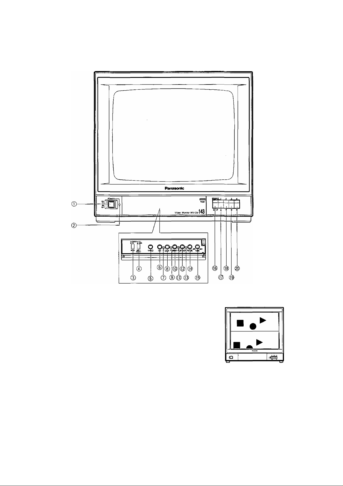
MAJOR OPERATING CONTROLS AND THEIR FUNCTIONS
FRONT VIEW
1. Power Switch (POWER)
This is a push-push type switch which turns the power
of the monitor on and off.
Press once and the switch remains down for turn
ing on the power of monitor.
Press again, the switch comes up (X) for turning off
the power of the monitor.
2. Power Indicator
3. Mode Selection Switch (STAND BY (^)/ ON (X))
ON: The picture of the camera will appear on the moni
tor.
STAND BY: The picture of the camera will not appear
on the monitor in the sequence mode, however the
picture can be observed at Video Output
Connector.
4. Input Selection Switch (EXT(^) CAMERA(X))
This selects the picture displayed on the monitor as ;
EXT: VTR playback picture which connected to Video
Input Connector can be observed.
CAMERA: Camera picture which is connected to
Camera Input Connectors can be observed.
5. Vertical Hold Control (V-HOLD)
This control is used to adjust the picture in vertically.
6. Tint Control (TINT)
Turn this control clockwise for purplish color of the pic
ture and turn this counterclockwise for greenish color
of the picture.
7. Tint Subcontrol
8. Color Control (COLOR)
Turn this control clockwise to increase the picture color
and turn this control counterclockwise to decrease the
picture color.
9. Color Subcontrol
-2-
Page 5
10. Bright Control (BRIGHT)
Turn this control clockwise to increase the picture
brightness and turn this control counterclockwise to
decrease the picture brightness.
15. Audio Controi (AUDIO, MIN/MAX)
Turn this control clockwise to increase the audio level
and turn this control counterclockwise to decrease the
audio level,
11. Bright Subcontrol
12. Contrast Control (CONTRAST)
Turn this control clockwise to increase the picture con
trast and turn this control counterclockwise to
decrease the picture contrast.
13. Contrast Subcontrol (CONTRAST)
14. Picture Adjustment (PICTURE)
Turn this control clockwise for sharp picture and turn
this control clockwise for soft picture.
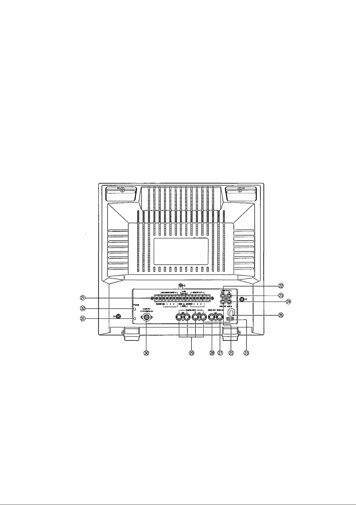
REAR VIEW
16. Sequence / Setup Selection Switch
(SEQUENCE/SETUP)
Press this switch more than 2 seconds to display the
Set Up menu.
17. Camera Selection Switch (1)/ Up Switch (A)
18. Camera Selection Switch (2) / Down Switch (T)
19. Camera Selection Switch (3) / Left Switch (<^)
20. Camera Selection Switch (4) / Right Switch (►)
21. External Control Connection Terminals
RECOVER
When the picture of the camera is selected by the
signal of Spot Monitor Control In, the monitor only
displays the picture of the selected camera.
To reset the picture of the selected camera and to
set to the sequence operation for the Color CCTV
System, use the reset signal from the time lapse
VTR.
SPOT MONITOR CONTROL IN
The terminals of the Spot Monitor Control In are
used to connect the intercom or alarm sensors for
the spot monitoring by short circuit between termi
nal 1,2, 3 or 4 and ground.
When the Camera Extension Unit is used, the
same spot monitoring are proceeded for terminal
5, 6 and 7 of the camera extension unit.
If the terminal 1 is shorted to the ground by inter
com or alarm sensors, the camera No.1 is select
ed and its picture is observed as spot monitoring.
The picture of the camera No.2, 3, 4, 5, 6, or 7
can be observed as the same way when the
Camera Extension Unit is used.
Note: The voltage of short circuit for terminal should be
0 - 0.2 volt when the intercom or alarm sensor is
activated.
ALARM CONTROL OUT
The terminals of the Alarm Control Out are used to
connect the buzzer or chime for sounding when
the terminals of the Spot Monitor Control In is
shorted to ground by intercom or alarm sensor.
-3-
Page 6

STANDBY-GND Connection
The connected buzzer or chime will sound when
the Mode Selection Switch is positioned at
STANDBY and the intercom or alarm is activated,
ALL MODE-GND Connection
The connected buzzer or chime will sound at
either position oi the Mode Selection Switch when
the intercom or alarm is activated.
REMOTE OUT Connection
The terminals for the Remote Out are used to con
nect the Remote Out are also used to connect the
Spot Monitor Control In for the Spot monitoring by
short circuit of terminal 1, 2, 3 or 4 when the two
color monitor is connected with Remote Controi
Unit for Auto Panning Head.
The power rate of the alarm should be DC 24V,
max. 100 mA.
If the power capacity of the remote is less than
100 mA at DC24V, the remote load can be con
nected at DC 24V, the remote load can not be
connected at the terminal directly. In this case, the
relay circuit should be used for the remote load.
22. Timing Select Output Connector
(TIMING SELECT, OUT)
This output connector produces the timing pulse sig
nals for switching the sequence operation of other
extensible systems such as another Color CCTV
Systems or sequential switcher system,
23. Timing Select Input Connector
(TIMING SELECT, IN)
This input connector is provided for the sequence
operation with timing pulses from the time lapse VTR or
another Color CCTV System.
24. Audio Input Connector (AUDIO IN)
Accepts the audio signal from the video camera with
microphone.
You can hear the VTR sound by setting the Input
Selection Switch to the EXT position.
25. Audio Output Connector (AUDIO OUT)
The audio signal is supplied from this connector to the
VTR.
29. Camera Input Connectors (CAMERA INPUT, 1/2/3/4)
The BNC type connectors are used to provide the
video output signal of the cameras to the additional
video tape recorder.
This connector supplies DC power and vertical drive
pulse to the camera and receive the video informations
from the cameras.
Notes:
• Be sure to connect only the specified camera.
• Connect the camera after making sure that the
monitor is off.
When the camera is connected while the monitor is on,
the camera will not be functioned by activating the pro
tection circuit for misconnection.
Caution:
The CAMERA INPUT 1 connector only can accept
the multiplexed VD (VD2) signal from the specified
Color Mini CCTV System Camera.
Even if the multiplexed VD (VD2) signal will be
supplied to the CAMERA INPUT 2, 3 or 4, this
monitor can not work correctly.
30. Camera Extension Input Connector
(CAMERA EXTENSION IN)
This is a 12-pin connector for the Camera Extension
unit when it is used for extending additional 3 cameras,
and the information are as;
Pin 1
Pin 2
Pin 3
Pin 4
Pin 5
Pin 6
Pin 7
Pin 8
Pin 9
Pin 10
Pin 11
Pin 12
31. Screen Control
This control is preset at the factory.
Do not adjust this control.
When the adjustment of this control is required, refer to
the qualified service personnel.
Logic Signal for Sequence
Logic Signal for Sequence
Logic Signal for Sequence
Video Input Signal
Ground
Logic Signal for Sequence
Logic Signal for Sequence
Logic Signal for Sequence
Logic Signal for Sequence
Logic Signal for Sequence
Vertical Drive Output Signal
DC Voltage for Cable Compensation
26. Power Cord
Caution: 120V AC supply only.
27. Video Input Connector (VIDEO IN)
This is a video input connector from VTR for playback
picture.
When you would like to observe the VTR playback pic
ture on this monitor, set the Input Selection Switch to
the EXT position and Mode Selection Switch to the ON
position.
28. Video Output Connector (VIDEO OUT)
The BNC type connector is used to provide the video
output signal of the cameras to the additional monitor
or video tape recorder.
The video output signal of the camera is provided from
this connector even when the Mode Selection Switch is
the STD BY position.
32. Focus Control (FOCUS)
This control is preset at the factory.
33. Camera Power On/Off Selection Switch
(CAMERA POWER, ON/OFF)
ON: Set this position to use with the specified Color
CCTV Camera.
OFF: Set this position to use with the specified Color
System Camera (Multiplexed VD (VD2) with gen
lock).
No power supply to the camera.
Caution:
Be sure to set this switch before camera connec
tion.
-4-
Page 7
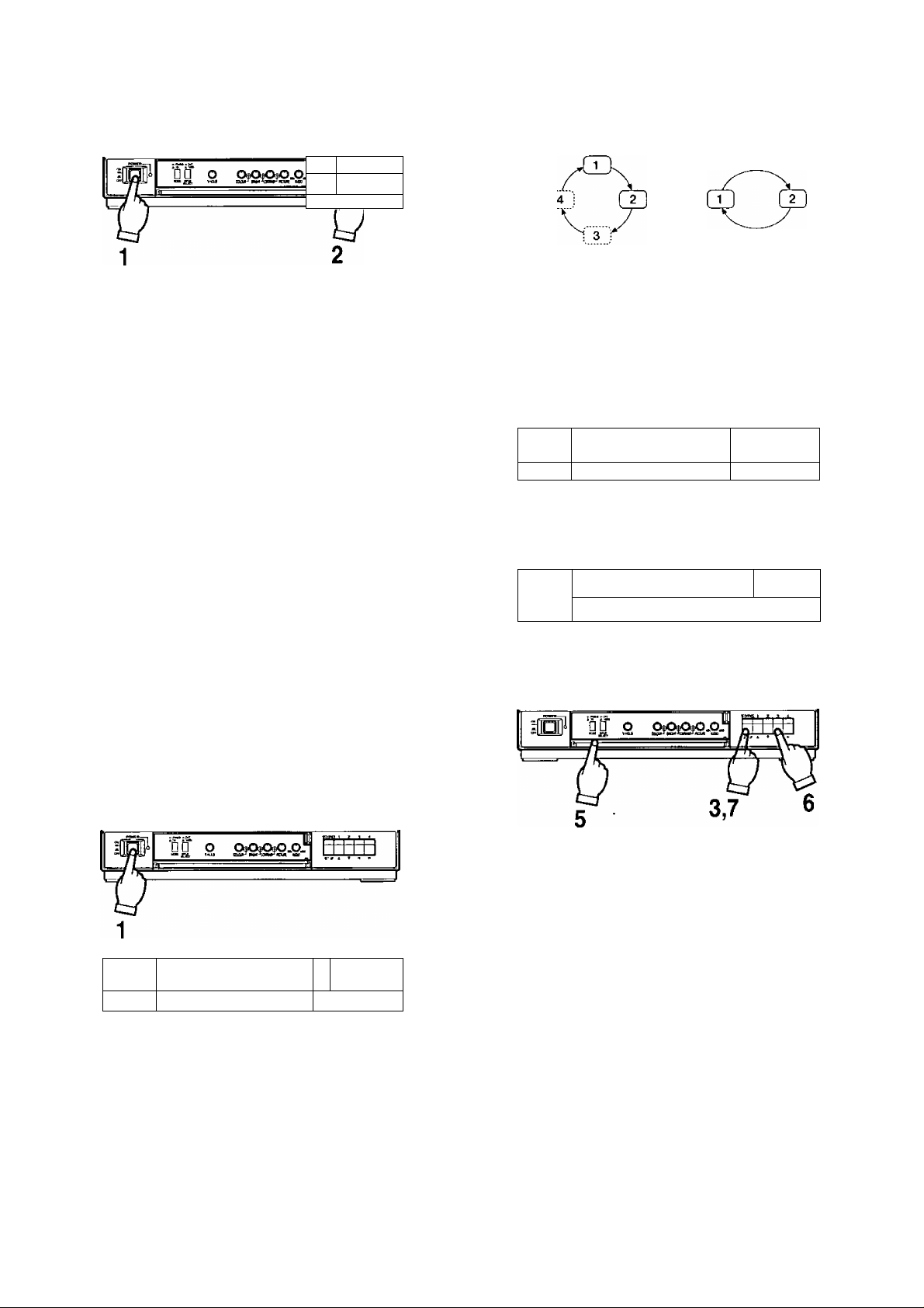
OPERATING PROCEDURES
i 5
I i 1 1
JaLU
------
/
Selection of Camera
1, Set the Power Switch on the front panel to the ON posi
tion by pressing once.
2. Press the desired Camera Selection Switch.
Notes :
1. The normal picture will not be displayed for a few
seconds after turning on the power of the monitor.
2. This monitor is in the sequence mode automatical
ly by turning on the power of this unit.
3. The desired camera can be observed on the mon
itor by pressing the desired Camera Selection
Switch even if this monitor is in the sequence
mode.
4. Also desired camera picture can be observed on
the monitor by pressing the desired Camera
Selection Switch even if this monitor is in the
Standby mode.
4. Set the desired sequential switching interval time with
the Set Up menu.
Note: The sequential switching features the automatic
bypass circuit by detecting the presence of the
DC power for the camera so that the input connec
tor with no camera connection is automatically
skipped.
Standby mode Monitoring picture
rjrai
e
----------------------
□ □ о 0teC3^O.O_
"2ft '«и ÉVI
до о ОрОшОвО.ОЛ
Ш-/ 1 . iH
-----------------------------------------------------------
1
Caution :
When the power switch of monitor is turned ON and
OFF repeatedly in the short period of time, the camera
may not be turned ON due to the operation of misconnection protection circuit.
In this case, leave the switch in the OFF position for a
few seconds before turning On again.
Sequence Mode (more than two cameras)
я| 1 1Ì 1J1 ^ 1
e
1. Set the Power Switch to the ON position by pressing
once.
2. Set the Mode Selection Switch to the ON position.
3. Press the Sequence / Set up Selection Switch more
than 2 seconds.
Д □ О OtóOteOfO.Ojh
fit Ruu'-^parti-'uaHiiiHPCiui ык
P
1. Set the Power Switch to the On position by pressing
once.
2. Set the Mode Selection Switch to the ON position.
3. Press the Sequential / Set Up Switch.
4. Set the Sequential switching interval with the Set Up
menu,
5. Set the Mode Selection Switch to the STDBY position.
The picture on the monitor disappears, however the
sequential switching is actually carried and the picture
can be observed at Video Output Connector on rear of
monitor by connecting additional monitor.
6. When the picture of the desired camera is observed /
monitored, press the desired Camera Selection Switch.
7. By pressing the Sequence / Set up Selection Switch
again, the picture on the monitor disappears and back
to the sequential switching at Standby mode.
-5-
Page 8

Connect the sensor switches and the Time Lapse VTR with the proper cables. The sensor should have an open-collector out
put or non-voltage contact.
\s
cm
Time Lapse VTR
ALARM I
REStIINRECOVER
OUT
GNO OUT
QND
Alarnn Input Connector (provided)
Pin No.
1
2
3 ch3 Input
4
5
6
7
8
9 chi earth
10 ch2 earth
11
12
13
14
15
Signals Wire Color
chi Input
ch2 Input
Brown
Red
Orange
ch4 Input
ch5 Input
Yellow
Green
ch6 Input Blue
ch7 Input
ch8 Input
Purple
Grey
Black
Black
ch3 earth Black
ch4 earth Black
ch5 earth
Black
ch6 earth Black
ch7 earth
Black
16 ch8 earth Black
Note: Be sure to insulate the wire(s) which is (are) not con
nected.
Alarm Input Connector
(provided)
The capacity of the Alarm Output Connector is 30V
DC maximum, 100mA or less
ALARM OUT
-6-
Page 9

1. Single Connection
A. Without VCR
ALARM/SEQ ALARM/SPOT
2. Parallel Connection
C. Without VCR
B. with VCR
ALARM/SEQ
D. With VCR
ALARM/SEQ
AU\RM/SPOT
ALARM/SPOT AURM/SEQ
-7-
Page 10

3-3. Timing Selection (TIMING SELECT) 3-7. Automatic Reset On/Off Setting (AUTO RESET)
** SET UP
CAMERA ID
AUDIO SELECT SEQ
TIMING SELECT
SEQ TIME ADJ 1 SEC SEQ TIME ADJ
ALARM BUZZER
ALARM TIME ADJ
AUTO RESET ON AUTO RESET
BRIGHT COMP
END SET UP
MENU ••
12 3 4 CAMERA ID
1 CAMERA
INTJ
OH ALARM BUZZER
60 SEC ALARM TIME ADJ
12 3 4 BRIGHT COMP
DISABLE
J j
The video / audio switching timing can be selected
from INT {internal) or EXT (external).
3-4. Sequential Time Adjustment (SEQ TIME ADJ)
** SET UP MENU
CAMERA ID
AUDIO SELECT
TIMING SELECT
SEQ TIME ADJ
ALARM BUZZER
ALARM TIME ADJ
AUTO RESET
BRIGHT COMP
END SET UP
The sequential time of the camera picture can be
selected.
12 3 4
L CAMERA
SEQ
INT
llTSECt
ON
60 SEC
ON
12 3 4
DISABLE
f
** SET UP
AUDIO SELECT SEQ
TIMING SELECT INT
END SET UP
Selects the Automatic Reset On/Off mode.
3-8. Bright Compensation Setting (BRIGHT COMP)
The bright adjustment can be made at each channel.
** SET UP MENU
CAMERA ID
AUDIO SELECT
TIMING SELECT
SEQ TIME ADJ
ALARM BUZZER
ALARM TIME ADJ
AUTO RESET
BRIGHT COMP
END SET UP
MENU **
1 CAMERA
[Il.2_3-4l
12 3 4
1 CAMERA
1 SEC
ON
60 SEC
tON}
12 3 4
DISABLE
12 3 4
SEQ
INT
1 SEC
ON
60 SEC
ON
DISABLE
3-5. Alarm Sound On/Off Setting (ALARM BUZZER)
** SET UP MENU
CAMERA ID
AUDIO SELECT
TIMING SELECT
SEQ TIME ADJ
ALARM BUZZER
ALARM TIME ADJ
AUTO RESET
BRIGHT COMP
END SET UP
12 3 4
1 CAMERA
SEQ
INT
1 SEC
tON]
60 SEC
ON
12 3 4
DISABLE
Alarm Buzzer On/Off mode can be selected in the
Alarm ON mode.
3-6. Alarm Time Adjustment (ALARM TIME ADJ)
** SET UP MENU **
CAMERA ID
AUDIO SELECT
TIMING SELECT
SEQ TIME ADJ
ALARM BUZZER
ALARM TIME ADJ
AUTO RESET
BRIGHT COMP
END SET UP
12 3 4
1 CAMERA
SEQ
INT
1 SEC
ON _
reo^sEC^j
ON
12 3 4
DISABLE
Selects the interval time of alarm signals at 1 to 60 sec
onds.
-8-
Page 11

SETUP OPERATION
Before entering the Set Up menu, remember the ALL
RESET operation in order to escape from the confusion as
follows.
(1) Confirm that the Mode Selection Switch is set to the
ON position, the Input Selection Switch is set to the
CAMERA position and Set Up menu is not displayed.
(2) Turn off the power of this monitor.
(3) Turn on the power of this monitor while pressing the
Set Up Switch and Right Switch simultaneously.
All adjustments and selections are reset to the factory
setup condition.
• Entering Setup Menu
Editing Set Up menu
f
** SET UP MENU
CAMERA ID 12 3 4
AUDIO SELECT SEQ
TIMING SELECT INT
SEQ TIME ADJ 1 SEC
ALARM BUZZER ON
ALARM TIME ADJ 60 SEC
AUTO RESET ON
BRIGHT COMP 1 . . 4
END -► SET UP
Press the Set Up Switch.
>
* *
1 CAMERA
DISABLE:
)
Mr
r
•• SET UP MENU **
CAMERA ID 12 3 4
AUDIO SELECT SEQ
TIMING SELECT INT
SEQ TIME ADJ 1 SEC
ALARM BUZZER ON
ALARM TIME ADJ 60 SEC
AUTO RESET ON
BRIGHT COMP 12 3 4
El ID SET UP DISABLE
Blinking
Press the Camera Selection Switches which is con
nected with the camera.
By pressing the Set Up Switch for more 2 seconds, the
“SET UP” menu is displayed on the monitor screen as
shown below.
By observing this menu, you can check the present
condition.
Refer to the following sections for details of each item.
After confirming the present condition and further
resetting of each item is not required, move the cursor
to the “END” position on the left bottom line and press
the Set Up Switch to return to the normal camera pic
ture mode.
Important notice
When the “SET UP DISABLE” is displayed on the
bottom line of the Set up menu, you can not enter
the actual mode setting. This prevents mis-opera-
tion of the mode setting.
1 CAMERA
r
** SET UP MENU
CAMERA ID 12 3 4
AUDIO SELECT
TIMING SELECT INT
SEQ TIME ADJ 1 SEC
ALARM BUZZER ON
ALARM TIME ADJ 60 SEC
AUTO RESET ON
BRIGHT COMP 1 . . 4
END SET UP
1 CAMERA
* *
SEQ
ENABLE ^
>
)
To enable the set up menu editing (resetting / readjust
ment), move the cursor to the bottom line by using the
Up Switch and Down Switch and move to the “SET UP
DISABLE” position by using the Right Switch or Left
Switch and press the Set Up Switch. “SET UP
ENABLE” is displayed.
Move the cursor to the desired item to be reset for
readjust through the “END” position.
Important Notice:
When the cursor is moved to the next position
(next item) after changing the data (ex. ON - OFF),
the latest data is written on the memory (Electronic
Erasable) and Programmable Read Only Memory
(EEPROM) and it remains until the further data
write is made even if the camera power is
switched off.
-9-
Page 12

Setting Procedure
1. Camera Identification Setting
(CAMERA ID)
** SET UP MENU •*
CAMERA ID ill 2 3 4 ^
AUDIO SELECT SEQ
TIMING SELECT INT
SEQ TIME ADJ 1 SEC
ALARM BUZZER OH
ALARM TIME ADJ 60 SEC
AUTO RESET OH
BRIGHT COMP 12 3 4
END SET UP DISABLE
Press the Down Switch (T).
** SET UP MENU **
CAMERA ID
AUDIO SELECT
TIMING SELECT
SEQ TIME ADJ
ALARM BUZZER
ALARM TIME ADJ
AUTO RESET
BRIGHT COMP
END SET UP
1 CAMERA
12 3 4
ll CAMERA
SEQ
INT
1 SEC
ON
SO SEC
ON
12 3 4
DISABLE
1-1. Move the cursor to the CAMERA ID and select the desired camera
by using the Left (■<) or Right {►) Switch.
To set the Camera ID Display On/Off mode, press the Setup
Switch.
1-2, After completing the procedure of item 1, move the cursor to the
second line by using the Down {T) Switch,
Set the Camera Identification according to the following procedure
(1-3) and press the Setup Switch.
To register the Camera Identification, put back the cursor to the
CAMERA ID.
Note: The Camera Identification setting is not memorized unless
the CAMERA ID is selected again.
1 -3. Selectable characters are shown in the following.
J
(-) (+)
0123456789;;ABCDEFGHIJKLMN
OPQRSTUVWXYZ"#'()
* + ,-./ = —> • (blank)
Character selection can be made with the Up (A) or Down {▼)
Switch.
Column selection can be made by the Left (-^) or Right {►)
Switch.
After completing the selection, press the Setup Switch.
To change the Camera ID of the other camera, press the Left (-^)
or Right {►) Switch.
Press the Setup Switch.
r
*• SET UP MENU **
CAMERA ID
AUDIO SELECT
TIMING SELECT
SEQ TIME ADJ
ALARM BUZZER
ALARM TIME ADJ
AUTO RESET
BRIGHT COMP
END SET UP
After completing the selection,
press the Setup Switch.
Г
** SET DP MEND **
CAMERA ID 12 3 4
AUDIO SELECT SEQ
TIMING SELECT INT
SEQ TIME ADJ 1 SEC
ALARH BUZZER ON
ALARH TIME ADJ 60 SEC
AUTO RESET ON
BRIGHT COMP 12 3 4
END SET UP DISABLE
Ч
Press the Right Switch (►■).
f
** SET DP MENU **
CAMERA ID 12 3 4
AUDIO SELECT
TIMING SELECT
SEQ TIME ADJ
ALARH BUZZER OH
ALARH TIME ADJ
AUTO RESET ON
BRIGHT COMP 12 3 4
END SET UP DISABLE
12 3 4
L 'camera
SEQ
INT
1 SEC
ON
60 SEC
ON
12 3 4
DISABLE
ll CAMERA
2]
SEQ
IHT
1 SEC
60 SEC
2. Audio Selection (AUDIO SELECT)
SET UP MENU **
CAMERA ID
AUDIO SELECT
TIMING SELECT
SEQ TIME ADJ
ALARM BUZZER
ALARM TIME ADJ
AUTO RESET
BRIGHT COMP
END SET UP
12 3 4
1 CAMERA
tSEQ': ^
IHT
1 SEC
ON
60 SEC
OH
12 3 4
DISABLE
2-1. Move the cursor to the “AUDIO SELECT” position.
Select the Sequential (SEQ) or Fixing (1,2,3 or 4) mode by using
the Left (◄) or Right (►) Switch.
2-2. In the Sequential mode, the audio signal is also switched accord
ing to the channel switching.
2-3. In the Fixing mode, the audio signal is fixed to the selected chan
nel,
3. Timing Selection (TIMING SELECT)
/
3-1. Move the cursor to the TIMING SELECT,
3-2. Select the Interna! Timing (INT) or External Timing (EXT) by using
the Left (4) or Right (►) Switch.
Note: Set this item to the “EXT” when this timing signal is input
from the other video monitor or time lapse VTR.
•• SET UP MEND **
CAMERA ID
AUDIO SELECT
TIMING SELECT
SEQ TIME ADJ
ALARM BUZZER
ALARM TIME ADJ
AUTO RESET
BRIGHT COMP
END SET UP
12 3 4
1 CAMERA
SEQ
[iNTj -4
1 SEC
ON
60 SEC
ON
12 3 4
DISABLE
-10-
Page 13

4. Sequential Time Adjustment
(SEQ TIME ADJ)
** SET UP MENU ••
CAMERA ID
AUDIO SELECT
TIMING SELECT
SEQ TIME ADJ
ALARM BUZZER
ALARM TIME ADJ
AUTO RESET
BRIGHT COMP
END SET UP
12 3 4
1 CAMERA
SEQ
lOT
И^ЗЕСЦ]
OH
60 SEC
ON
12 3 4
DISABLE
4-1. Move the cursor to the SEQ TIME ADJ.
4-2. Select the sequential time by using the Left (
or
Right (►) SvAfitch,
Sequential time can be selected from approx. 1, 2, 3,
4, 5, 6, 7. 8, 9, 10, 15, 20, 25 or 30 sec.
5. Alarm Sound On/Off (ALARM BUZZER)
SET UP MENU **
CAMERA ID
AUDIO SELECT
TIMING SELECT
SEQ TIME ADJ
ALARM BUZZER
ALARM TIME ADJ
AUTO RESET
BRIGHT COMP
END SET UP
12 3 4
L CAMERA
SEQ
INT
1 SEC
[ONj
60 SEC
ON
12 3 4
DISABLE
7. Auto Reset Setting (AUTO RESET)
SET UP MENU **
CAMERA ID
AUDIO SELECT
TIMING SELECT
SEQ TIME ADJ
ALARM BUZZER
ALARM TIME ADJ
AUTO RESET
BRIGHT COMP
END SET UP
12 3 4
L CAMERA
SEQ
INT
1 SEC
ON
60 SEC
[ON]
12 3 4
DISABLE
7-1. Move the cursor to AUTO RESET.
7-2. Auto Reset On/Off nnode can be selected by using the
Left (-^) or Right (►) Switch.
The alarm mode will be reset automatically at 60 sec,
after the sensor signal is received.
8. Bright Compensation Setting
(BRIGHT COMP)
8-1. Move the cursor to the “BRIGHT COMP”.
8-2. The desired camera can be selected by using the Left
{◄) or Right {►) Switch.
8-3. Bright Compensation On/Off mode can be selected by
using the Set Up Switch.In the sequential mode, this
function can give the suitable condition to the picture
during the sequential mode.
5-1 Move the cursor to the ALARM BUZZER.
5-2. Alarm Sound On/Off mode can be selected by using
the Left (-<) or Right (►) Switch.
This monitor sounds the alarm for the preset time when
an alarm signal is received.
6. Alarm Time Adjustment
(ALARM TIME ADJ)
SET UP MENU **
CAMERA ZD
AUDIO SELECT
TIMING SELECT
SEQ TIME ADJ
ALARM BUZZER
ALARM TIME ADJ
AUTO RESET
BRIGHT COMP
END SET UP
6-1, Move the cursor to the ALARM TIME ADJ.
6-2. Set the time duration of the alarm buzzer by using the
Left {-^) or Right (►) Switch.
Alarm buzzer can be selected from approx, 1,5, 10,
20, 30, 40, 50 or 60 sec.
12 3 4
L CAMERA
SEQ
INT
1 SEC
ON
'60.SECD
ON
12 3 4
DISABLE
□
Л
о
SET UP MENU
CAMERA ID
AUDIO SELECT
TIMIHO SELECT
SEQ TIME ADJ
ALARM BUZZER
ALARM TIME ADJ
AUTO RESET
BRIGHT COMP
END SET UP
□
л
о
12 3 4
1 CAMERA
SEQ
INT
1 SEC
OH
60 SEC
OH
1 . . 4
DISABLE
fì.
“BRIGHCOMP" ON OFF OFF ON
Caution:
This function only works on the screen in the
sequential mode.
The video signal can not be supplied from Video
Output Connector.
When observing the playback picture, picture
adjustment should be made by using the Bright or
Contrast Control on the front panel.
-11-
Page 14

CONNECTIONS
Precautions:
1. These connections should be made by qualified service personnel or system installers.
2. Keep the power switch of the monitor, optional camera, optional camera extension unit and in the OFF position during the connection.
Connection with camera
Camera
Connect the single coaxial cables between the cam
eras and monitor (CAMERA INPUT). The maximum
coaxial cable length is as;
Coaxial
Cable Type
RG-59/U
RG-6/U
The maximum DC-resistance.. of „the., coaxial
between the cameras and video monitor is 20 a.
Maximum
Cable Length
200 m (660 ft.)
500 m (1650 ft.)
DC R/1000 ft. of
Inner Conductor
Less than 30
Less than 12 ii
Connection with Sequential Switcher
Color Monitor WV-CM143
cable
Color Monitor WV-CM143
Cautions
1. Keep the power switch to OFF position this monitor
during the camera connection.
2. Connect the specified cameras (multiplexed VP).
If other camera is connected, the Color CCTV system
will not be operated due to the protection circuit for
misconnection.
3. By setting the Camera power On/Off switch to the OFF
position, the specified camera (multiplexed VP) can be
connected.
This system allows to synchronize the timing pulse in the monitor side.
• Set Up menu setting
TIMING SELECT should be set to INT position.
• Sequential Switcher setting
Time Adjustment Control of the Sequential Switch should be set to
EXT VTR.
-12-
Page 15

Basic System with Optional Camera
Extension Unit
Connect the single coaxial cables between the cam
eras and monitor/camera extension unit (CAMERA
INPUT).
Connect the camera extension cable from the camera
extension unit at the Camera Extension Input
Connector on the monitor.
Camera Extension Units can be connected up to 31
units.
■ Additional Basic System
• Connect the coaxial cables between the cameras and
monitor.
• Connect the Sync Timing Cable between the monitors.
TIMING SELECT: INT
Color Monitor WV-CM143
Note: The Timing Selection of the master monitor is posi
tioned at INT and the Timing Selection of the slave
monitor is positioned at EXT.
Caution; The CAMERA INPUT 1 connector can accept the
Multiplexed VD (VD2) signal from the specified CCTV
System Color Camera.
Be sure to connect the camera after turning off the
Camera Power On/Off Selection Switch.
-13-
Page 16

Connection with the VTR
Color Monitor WV-CM143
Note: Avoid the following connection when monitoring the
playback picture of VTR.
Color Monitor
WV-CM143
BNC Connector
Coaxial Cable
VIDEO
OUTPUT
Time Lapse VTR
Connect a coaxial cable between the video output signal of
the VTR and the VIDEO IN of this monitor.
Connection with the Intercom and Alarm Sensors/Switches
Noise
The wiring for intercom system and alarm sensor
/switches should be two wires.
The power source for intercom system and alarm sen-
sors/switches should be less than DC 12V.
When the intercom or alarm sensor/switch is activated,
the line voltage for intercom or alarm sensor/switch
should be DC 0-0.2V.
Power source level
Less than 12V DC
Calling period or activated
V. r7
period (less than 0.2V)
OV
For example, the wiring length for intercom system is as fol
lows ;
Wires
(mm/Q‘ty)
0.18/12 22
Equivalent
AWG SWG
23 150m
0.18/20 20 21
0.18/30 18
0.18/50
19 400m
16
17 600m
Maximum
Wiring length
250m
AWG: American Wire Gauge
SWG; British Legal Standard Wire Gauge
The polarity for the intercom system and the Spot Monitor
Control In of the monitor should be matched. Make sure the
polarity of the intercom system by tester (meter).
Mater Unit
There is a limitation for the wiring length among the inter
com system, alarm sensors system, optional units and
video monitor.
-14-
Page 17

Do not connect the intercom system of AC power source.
Two modes for the Alarm Control Out are selected.
STD BY: This terminal is performed at only Standby mode
of the Mode Selection Switch when the SPOT MONI
TOR CONTROL IN is activated by intercom or alarm
sensor/switch.
ALL MODE: This terminal is performed at either Standby or
On Mode of the Mode Selection Switch when the SPOT
MONITOR CONTROL IN is activated by intercom or
alarm sensor/switch.
The polarity for the alarm and Alarm Control Output of the
monitor should be matched.
The power rate of the alarm should be DC24V, max.
100mA.
If the power capacity of the alarm is less than 100mA at DC
24V, the alarm can be connected at the terminal of Alarm
Control Out directly.
If the power capacity of the alarm is more than 100mA at
DC24V, the alarm can not be connected at terminal direct
ly. In this case, the relay circuit should be used for the
alarm.
-15-
Page 18

SYSTEM CONNECTION
■ Connection with Time Lapse VTR
Main Unit
Notes:
1. When the alarm signal operation will be made in this system, the alarm signal should be supplied from the Time Lapse VTR.
2. When you want to cancel the alarm signal from the monitor side, supply the reset signal of this monitor to the RESET IN con
nector of the VTR.
In this connection, the polarity of both signals should be positive,
3. Refer to the Operating Instructions of Time Lapse VTR for the recording detail.
-16-
Page 19

Remote Control for Video Monitor
Notes:
1, When the alarm signal operation will be made in this
system Connect the Time Date Generator according to
the need.
2. When the alarm signal operation will be made in this
system, the alarm signal should be supplied from the
Time Lapse VTR.
Refer to the Operating Instructions of Time Lapse VTR
for details.
VTR mode
Recording
Playback
Monitor (A)
CAMERA
EXT EXT
Setting Position
Monitor (B)
EXT
3. Input Selection Switch of this monitor should be set as
shown below.
4. The Color Monitor WV-CM143 (B) can not connect to
the camera.
5. The Color Monitor WV-CM143 (A) does not allow the
Color Monitor WV-CM143 (B) to recover into the
sequential mode,
6. Refer to the Operating Instructions of Time Lapse VTR
for the recording detail.
-17-
Page 20

SPECIFICATIONS
Power Source:
Power Consumption:
CRT Size:
Actual Visual Size:
Camera Input:
Video Input:
Video Output:
Power Supply for Camera:
Camera Switching:
Sequential Switching :
Skip :
Auto Reset:
Resolution :
Sweep Linearity :
Sweep Distortion ■
Scanning Frequency:
Audio Input:
Audio Output :
Speaker Output:
Intercom / Sensor Input:
Alarm Output
Video Standby mode :
Standby mode:
Alarm time:
Timing :
Extension Adaptor Input:
Camera Extension Length
Ambient Operating Temperature
Dimension :
Weight :
120V AC 60 Hz
Approx, 110W
36.8 cm (14* diagonal)
33.5 cm (13“ diagonal)
1.0 V[p-p]/75 n, composite x 4 (BNC)
1.0 V[p-p]/75 n, composite x 1 (3NC)
1.0 V[p-p]/75 ii, composite x 1 (BNC)
Regulated current multiplex method (INPUT 1: selectable Camera Power On/Off)
Manual/Auto (sequence) with auto bypass
Approx. 1,2, 3, 4, 5, 6, 7, 8, 9, 10, 15, 20, 25, 30 sec. (selectable with Set Up menu)
Automatically
Automatic reset circuit can function at 60 sec. after receiving the sensor signal.
(Auto reset on/off mode can be selected with set up menu)
More than 370 lines at center
Horizontal: 5% or less
Vertical: 5% or less
Horizontal: 15.734 kHz
Vertical: 59.94 Hz
-8 dB/Hi-z (pin-jack)
-10 dB/100 Q (pin-jack)
1.0 W
1 circuit par each camera
1 circuit
1 circuit
Approx. 1,5, 10, 20, 30, 40, 50, 50 sec. (selectable with Set Up menu)
Internal / External (electable with Set Up menu)
12-pin connector
Coaxial Maximum DC R/1000 ft. of
Cable Type Cable Length Inner Conductor
RG-59/U 200 m (660 ft.) Less than 30 ii
RG-6/U 500 m (1650 ft.) Less than 12 ii
The maximum DC-resistance of the coaxial cable between the cameras and video
monitor is 20
-10“C - +50°C (14°F - +122°F)
370 (W) X 354 (H) X 389 (D) mm [14-9/16"(W) x 13-1/2"(H) x 15-5/16"(D)]
Approx. 11 kg (2.4 lbs.)
Weights and dimensions shown are approximate.
Specifications are subject to change without notice.
-18-
Page 21

Page 22

Panasonic
Broadcast & Television Systems Company
Division of Matsushita Electric Corporation of America
IMAGING SYSTEMS DIVISION
Executive Office: One Panasonic Way 3E-7, Secaucus, New Jersey 07094
Regional Offices;
Northeast: 43 Hartz Way, Secaucus, NJ 07094 (201 > 346-7303
Southeast: 1225 Northbrook Parkway, Suite 1-160, Suwanee, GA 30174 {770> 338-6835
Midwest: 1707 North Randall Road, Elgin, IL 60123 (708) 468-5200
Southwest: 4500 Amon Carter Blvd., Fort Worth, TX 76155 (817) 685-1117
Western: 6550 Katetia Ave. 17A-5, Cypress, CA 90630 (714) 373-7265
MATSUSHITA ELECTRIC OF CANADA LIMITED
5770 Ambler Drive, Mississauga, Ontario, L4W 2T3 Canada (905)624-5010
PANASONIC SALES COMPANY
DIVISION OF MATSUSHITA ELECTRIC OF PUERTO RICO, INC.
San Gabriel Industrial Park, 65th Infantry Ave. KM. 9,5 Carolina, Puerto Rico 00630 (809)750-4300
N0496-0
YWV8ÛA4273AN Printed in Japan
(N) 13
 Loading...