

Page 1

Colour Monitor
WV-CM143
Before attempting to connect or operate this product, please read these instructions completely
FRANÇAIS DEUTSCH ENGLISHESPAÑOL
Page 2
The serial number of this product may be found on the
bottom of the unit.
You should note the serial number of this unit in the
space provided and retain this book as a permanent
record of your purchase to aid identification in the event
of theft.
Model No.
Serial No.
THIS APPARATUS MUST BE EARTHED.
To ensure safe operation the three-pin plug supplied must be inserted only into a standard three-pin power point which is effectively
earthed through the normal household wiring. Extension cords used
with the equipment must be three-core and be correctly wired to provide connection to earth. Wrongly wired extension cords are a major
cause of fatalities.
The fact that the equipment operates satisfactorily does not imply
that the power point is earthed and that the installation is completely
safe. For your safety, if in any doubt about the effective earthing of
the power point, consult a qualified electrician.
The lightning flash with arrowhead symbol, within an equilateral triangle, is
interned to alert the user to the presence
of uninsulated "dangerous voltage" within
the product's enclosure that may be of
sufficient magnitude to constitute a risk of
electric shock to persons.
The exclamation point within an equilateral triangle is intended to alert the user
to the presence of important operating
and maintenance (servicing) instructions
in the literature accompanying the appliance.
WARNING:
TO PREVENT FIRE OR SHOCK HAZARD, DO NOT EXPOSE THIS APPLIANCE TO RAIN OR MOISTURE.
CAUTION:
TO REDUCE THE RISK OF ELECTRIC SHOCK,
DO NOT REMOVE COVER (OR BACK), NO USER
SERVICEABLE PARTS INSIDE.
REFER SERVICING TO QUALIFIED SERVICE
PERSONNEL.
CAUTION
RISK OF ELECTRIC SHOCK
DO NOT OPEN
For Australia
FOR YOUR SAFETY PLEASE READ THE FOLLOWING TEXT CAREFULLY.
This appliance is supplied with a moulded three pin mains plug for your
safety and convenience.
A 13 amp fuse is fitted in this plug.
Should the fuse need to be replaced please ensure that the replacement
fuse has a rating of 13 amp and that it is approved by ASTA or BSI to
BS1362.
Check for the ASTA mark
H or the BSI mark G on the body of the
fuse.
If the plug contains a removable fuse cover you must ensure that it is
refitted when the fuse is replaced.
If you lose the fuse cover the plug must not be used until a replacement
cover is obtained.
A replacement fuse cover can be purchased from your local Panasonic
Dealer.
IF THE FITTED MOULDED PLUG IS UNSUITABLE FOR THE SOCKET OUTLET IN YOUR HOME THEN THE FUSE SHOULD BE
REMOVED AND THE PLUG CUT OFF AND DISPOSED OF SAFELY.
THERE IS A DANGER OF SEVERE ELECTRICAL SHOCK IF THE
CUT OFF PLUG IS INSERTED INTO ANY 13 AMP SOCKET.
If a new plug is to be fitted please observe the wiring code as shown
below.
If in any doubt please consult a qualified electrician.
WARNING: This apparatus must be earthed.
IMPORTANT
The wires in this mains lead are coloured in accordance with the following code.
Green-and-yellow: Earth
Blue: Neutral
Brown: Live
As the colours of the wire in the mains lead of this appliance may not
correspond with the coloured markings identifying the terminals in your
plug, proceed as follows.
The wire which is coloured green-and-yellow must be connected to
the terminal in the plug which is marked with the letter E or by the earth
symbol
I or coloured green or green-and-yellow.
The wire which is coloured blue must be connected to the terminal in
the plug which is marked with the letter N or coloured black.
The wire which is coloured brown must be connected to the terminal
in the plug which is marked with the letter L or coloured red.
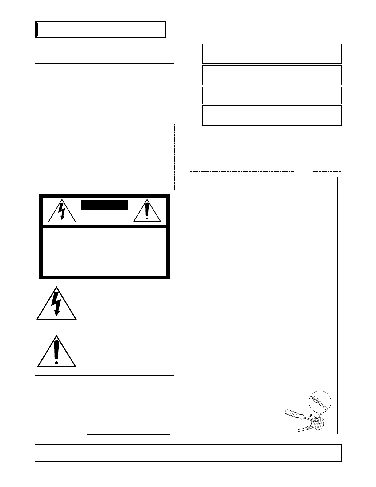
How to replace the fuse
Open the fuse compartment with
a screwdriver and replace the fuse
and fuse cover.
For U.K.
ENGLISH VERSION
We declare under our sole responsibility that the product to which
this declaration relates is in conformity with the standards or other
normative documents following the provisions of Directive
EEC/89/336.
Noi dichiariamo sotto nostra esclusiva responsabilità che il prodotto
a cui si riferisce la presente dichiarazione risulta conforme ai
seguenti standard o altri documenti normativi conformi alle disposizioni della direttiva CEE/89/336.
Wij verklaren als enige aansprakelijke, dat het product waarop deze
verklaring betrekking heeft, voldoet aan de volgende normen of
andere normatiefve dokumenten, overeenkomstig de bepalingen
van Richtlijn 89/336/EEC.
Vi erklærer os eneansvarlige for, at dette produkt, som denne
deklaration omhandler, er i overensstemmelse med den følgende
standarder eller andre normative dokumenter i følge bestemmelserne i direktiv 89/336/EEC.
Vi deklarerar härmed värt fulla ansvar för att den produkt till vilken
denna deklaration hänvisar är i överensstämmelse med standarddokument, eller andra normativa dokument som framstölls i Direktiv
89/336/EEC.
Ilmoitamme yksinomaisella vastuullamme, että tuote, jota tämä
ilmoitus koskee, noudattaa seuraavia standardeja tai muita ohjeellisia asiakirjoja, jotka noudattavat direktiivin 89/336/EEC. säädöksiä.
Vi erklærer oss alene ansvarlige for at produktet som denne
erklæringen gjelder for, er i overensstemmelse med følgende
normer eller andre normgivende dokumenter som fælger bestemmelsene i direktiv 89/336/EEC.
Page 3

CONTENTS
PREFACE ............................................................................................................................................................................................ 1
FEATURES .......................................................................................................................................................................................... 1
PRECAUTIONS ................................................................................................................................................................................... 1
MAJOR OPERATING CONTROLS AND THEIR FUNCTIONS ............................................................................................................ 2
OPERATING PROCEDURES .............................................................................................................................................................. 5
SETUP OPERATION ........................................................................................................................................................................... 9
CONNECTION .................................................................................................................................................................................... 12
SYSTEM CONNECTION .....................................................................................................................................................................16
SPECIFIACATIONS ............................................................................................................................................................................ 18
The model numbers listed in this Operating Instructions have no suffixed attached to it.
ENGLISH
Page 4

-1-
FEATURES
• As many as 4 Solid State Colour Cameras can be connected to Colour Monitor WV-CM143 with an alarm feature. This Colour Cameras can be added by using the
Camera Extension Unit WV-AD110A.
• One video output displays each camera in sequence
and any camera switched to the spot monitor position
for the use of an additional monitor or video tape
recorder.
• Monitor has 14" diagonal screen (13" diagonal actual
visual size)
• Sequential switching interval selectable from 1, 2, 3, 4,
5, 6, 7, 8, 9, 10, 15, 20, 25 or 30 sec.
• Built-in protection circuit for any misconnection.
• STANDBY mode for no picture on the monitor during
the sequential switching.
• Alarm control output for a buzzer or chime.
• Alarm period selectable from 1, 5, 10,20, 30, 40, 50 or
60 sec.
• The CCTV camera with michrophone can be connected with this monitor.
• VTR playback picture can be observed.
PRECAUTIONS
• Do not block the ventilation slots.
Do place the colour monitor at least 5 cm apart from
the wall.
• Do not expose the monitor to water or moisture.
Do not operate the monitor if it becomes wet. Do take
immediate action if ever the monitor does become wet.
Turn power off and refer servicing to qualified service
personnel. Moisture can damage the monitor and also
create the danger of electric shock.
PREFACE
The Panasonic's WV-CM143 Colour Monitor is designed
for use with the specified Colour CCTV Camera.
Up to four cameras can be connected with this monitor
sequential or manual switching for these cameras is available.
And also by the combination with the intercom or sensor
unit, CCTV system enables.
• Reset input for sequential switching from Time Lapse
VTR.
• Automatic bypass circuit for skipping no camera connection.
• Built-in Automatic Reset Selection function for Spot
Monitor Control Input. The automatic reset time is preset to approx. 60 seconds.
• The following functions are available by using the Set
Up menu.
• Camera Identification Display
• Audio Selection
• Timing Selection
• Sequential Time Adjustment
• Alarm Buzzer Setting
• Alarm Time Adjustment
• Automatic Reset
• Bright Compensation Setting
• The specified Colour CCTV System Camera (Multiplexed VD (VD2) with gen-lock) can be used with this monitor due to the Camera Power Selection Switch. (CAMERA INPUT 1 Connector)
• Do not attempt to disassemble the monitor. To prevent
electric shock, do not remove screws or cover. There
are no user-serviceable parts inside. Refer servicing to
qualified service personnel.
• Do not drop the metallic parts through slots.
This action could permanently damage the monitor.
Do turn power off immediately and refer servicing to
qualified service personnel.
Page 5

ON
OFF
POWER
SEQUENCE
1 2 3 4
SET UP
PUSH
Video Monitor WV-CM
143
CAMERA
EXT
INPUT
SELECT
ON
STAND BY
MODE
V-HOLD
COLOR BRIGHT
CONTRAST
PICTURE AUDIO
.MAXMIN.
COLOR
TINT
-2-
MAJOR OPERATING CONTROLS AND THEIR FUNCTIONS
■ FRONT VIEW
q
w
e
r
t
yuio!0
!1
!2
!3
!4
!5
!6
!7
!8
6. Colour Control (COLOUR)
Turn this control clockwise to increase the picture
colour and turn this control counterclockwise to
decrease the picture colour.
7. Colour Subcontrol
8. Bright Control (BRIGHT)
Turn this control clockwise to increase the picture
brightness and turn this control counterclockwise to
decrease the picture brightness.
5. Vertical Hold Control (V-HOLD)
This control is used to adjust the picture in vertically.
1. Power Switch (POWER)
This is a push-push type switch which turns the power
of the monitor on and off.
Press once and the switch remains down (
) for turning on the power of monitor.
Press again, the switch comes up (
) for turning off
the power of the monitor.
2. Power Indicator
3. Mode Selection Switch (STAND BY
/ ON )
ON: The picture of the camera will appear on the moni-
tor.
STAND BY: The picture of the camera will not appear
on the monitor in the sequence mode, however the
picture can be observed at Video Output
Connector (26).
4. Input Selection Switch (EXT(
) CAMERA( )
This selects the picture displayed on the monitor as ;
EXT: VTR playback picture which connected to Video
Input Connector(25) can be observed.
CAMERA: Camera picture which is connected to
Camera Input Connectors (27) can be observed.
POWER
ON
OFF
VIDEO Y/C
1 2 3 4
PAL
NTSC
(3.58)
M.NTSC
(4.43)
INPUT SELECT
Page 6

-3-
■ REAR VIEW
9. Bright Subcontrol
10. Contrast Control (CONTRAST)
Turn this control clockwise to increase the picture contrast and turn this control counterclockwise to
decrease the picture contrast.
11. Contrast Subcontrol (CONTRAST)
12. Picture Adjustment (PICTURE)
Turn this control clockwise for sharp picture and turn
this control clockwise for soft picture.
13. Audio Control (AUDIO, MIN/MAX)
Turn this control clockwise to increase the audio level
and turn this control counterclockwise to decrease the
audio level.
14. Sequence / Setup Selection Switch (SEQUENCE /
SETUP)
Press this switch more than 2 seconds to display the
Set Up menu.
15. Camera Selection Switch (1)/ Up Switch (D)
16. Camera Selection Switch (2) / Down Switch (C)
17. Camera Selection Switch (3) / Left Switch (A)
18. Camera Selection Switch (4) / Right Switch (B)
@0
@1
@2
@3 #1
@4
@5 @6 @7 @8
@9
!9
19. External Control Connection Terminals
RECOVER
When the picture of the camera is selected by the
signal of Spot Monitor Control In, the monitor only
displays the picture of the selected camera.
To reset the picture of the selected camera and to
set to the sequence operation for the Colour CCTV
System, use the reset signal from the time lapse
VTR.
SPOT MONITOR CONTROL IN
The terminals of the Spot Monitor Control In are
used to connect the intercom or alarm sensors for
the spot monitoring by short circuit between terminal 1, 2, 3 or 4 and ground.
When the Camera Extension Unit is used, the
same spot monitoring are proceeded for terminal
5, 6 and 7 of the camera extension unit.
If the terminal 1 is shorted to the ground by intercom or alarm sensors, the camera No.1 is selected and its picture is observed as spot monitoring.
The picture of the camera No.2, 3, 4, 5, 6, or 7
can be observed as the same way when the
Camera Extension Unit is used.
Note: The voltage of short circuit for terminal should be
0 - 0.2 volt when the intercom or alarm sensor is
activated.
ALARM CONTROL OUT
The terminals of the Alarm Control Out are used to
connect the buzzer or chime for sounding when
the terminals of the Spot Monitor Control In is
shorted to ground by intercom or alarm sensor.
#0
FOCUS
CAMERA
EXTENSION IN
4321
ALARM
CONTROL
STDBY
MODE
4 3 2 1
SPOT MONITOR CONTROL IN
GNDRECOVER
REMOTE OUT
4321
RESETGNDALL
CAMERA INPUT
TIMING SELECT
OUT
AUDIO OUT AUDIO IN
VIDEO OUT VIDEO IN
IN
CAMERA POWER
ON
OFF
Page 7

-4-
STANDBY-GND Connection
The connected buzzer or chime will sound when
the Mode Selection Switch is positioned at
STANDBY and the intercom or alarm is activated.
ALL MODE-GND Connection
The connected buzzer or chime will sound at
either position of the Mode Selection Switch (3)
when the intercom or alarm is activated.
REMOTE OUT Connection
The terminals for the Remote Out are used to connect the Remote Out are also used to connect the
Spot Monitor Control In for the Spot monitoring by
short circuit of terminal 1, 2, 3 or 4 when the two
colour monitor is connected with Remote Control
Unit for Auto Panning Head.
The power rate of the alarm should be DC 24V,
max. 100 mA.
If the power capacity of the remote is less than
100 mA at DC24V, the remote load can be connected at DC 24V, the remote load can not be
connected at the terminal directly. In this case, the
relay circuit should be used for the remote load.
20. Timing Select Output Connector (TIMING SELECT,
OUT)
This output connector produces the timing pulse signals for switching the sequence operation of other
extensible systems such as another Colour CCTV
Systems or sequential switcher system.
21. Timing Select Input Connector (TIMING SELECT,
IN)
This input connector is provided for the sequence
operation with timing pulses from the time lapse VTR or
another Colour CCTV System.
22. Audio Input Connector (AUDIO IN)
Accepts the audio signal from the video camera with
microphone.
You can hear the VTR sound by setting the Input
Selection Switch to the EXT position.
23. Audio Output Connector (AUDIO OUT)
The audio signal is supplied from this connector to the
VTR.
24. Power Cord
Caution: The supplied power cord is designed for use
on the supplied 220-240V AC supply only.
25. Video Input Connector (VIDEO IN)
This is a video input connector from VTR for playback
picture.
When you would like to observe the VTR playback picture on this monitor, set the Input Selection Switch to
the EXT position and Mode Selection Switch to the ON
position.
26. Video Output Connector (VIDEO OUT)
The BNC type connector is used to provide the video
output signal of the cameras to the additional monitor
or video tape recorder.
The video output signal of the camera is provided from
this connector even when the Mode Selection Switch is
the STD BY position.
27. Camera Input Connectors (CAMERA INPUT, 1/2/3/4)
The BNC type connectors are used to provide the
video output signal of the cameras to the additional
video tape recorder.
This connector supplies DC power and vertical drive
pulse to the camera and receive the video informations
from the cameras.
Notes:
• Be sure to connect only the specified camera.
• Connect the camera after making sure that the
monitor is off.
When the camera is connected while the monitor is on,
the camera will not be functioned by activating the protection circuit for misconnection.
Caution:
The CAMERA INPUT 1 connector only can accept
the multiplexed VD (VD2) signal from the specified
Colour Mini CCTV System Camera.
Even if the multiplexed VD (VD2) signal will be
supplied to the CAMERA INPUT 2, 3 or 4, this
monitor can not work correctly.
28. Camera Extension Input Connector
This is a 12-pin connector for the Camera Extension
unit when it is used for extending additional 3 cameras,
and the information are as;
Pin 1 : Logic Signal for Sequence
Pin 2 : Logic Signal for Sequence
Pin 3 : Logic Signal for Sequence
Pin 4 : Video Input Signal
Pin 5 : Ground
Pin 6 : Logic Signal for Sequence
Pin 7 : Logic Signal for Sequence
Pin 8 : Logic Signal for Sequence
Pin 9 : Logic Signal for Sequence
Pin 10 : Logic Signal for Sequence
Pin 11 : Vertical Drive Output Signal
Pin 12 : DC Voltage for Cable Compensation
29. Screen Control
This control is preset at the factory.
Do not adjust this control.
When the adjustment of this control is required, refer to
the qualified service personnel.
30. Focus Control (FOCUS)
This control is preset at the factory.
31. Camera Power On/Off Selection Switch
(CAMERA POWER, ON/OFF)
ON: Set this position to use with the specified Colour
CCTV Camera.
OFF: Set this position to use with the specified Colour
System Camera (Multiplexed VD(VD2) with genlock).
No power supply to the camera.
Caution:
Be sure to set this switch before camera connection.
Otherwise, it may damage this monitor.
Page 8

-5-
OPERATING PROCEDURES
Selection of Camera
1. Set the Power Switch (1) on the front panel to the ON
position by pressing once.
2. Press the desired Camera Selection Switch.
Notes :
1. The normal picture will not be displayed for a few
seconds after turning on the power of the monitor.
2. This monitor is in the sequence mode automatically by turning on the power of this unit.
3. The desired camera can be observed on the monitor by pressing the desired Camera Selection
Switch even if this monitor is in the sequence
mode.
4. Also desired camera picture can be observed on
the monitor by pressing the desired Camera
Selection Switch even if this monitor is in the
Standby mode.
Caution :
When the power switch of monitor is turned ON and
OFF repeatedly in the short period of time, the camera
may not be turned ON due to the operation of misconnection protection circuit.
In this case, leave the switch in the OFF position for a
few seconds before turning On again.
Sequence Mode (more than two cameras)
1. Set the Power Switch (1) to the ON position by pressing once.
2. Set the Mode Selection Switch (3) to the ON position.
3. Press the Sequence / Set up Selection Switch (14)
more than 2 seconds.
Note: The sequential switching features the automatic
bypass circuit by detecting the presence of the
DC power for the camera so that the input connector with no camera connection is automatically
skipped.
Standby mode Monitoring picture
1. Set the Power Switch(1) to the On position by pressing
once.
2. Set the Mode Selection Switch (3) to the ON position.
3. Press the Sequential / Set Up Switch.
4. Set the Sequential switching interval with the Set Up
menu.
5. Set the Mode Selection Switch (3) to the STDBY position.
The picture on the monitor disappears. however the
sequential switching is actually carried and the picture
can be observed at Video Output Connector on rear of
monitor by connecting additional monitor.
6. When the picture of the desired camera is observed /
monitored, press the desired Camera Selection Switch.
7. By pressing the Sequence / Set up Selection Switch
(14) again, the picture on the monitor disappears and
back to the sequential switching at Standby mode.
4. Set the desired sequential switching interval time with
the Set Up menu.
ON
OFF
1
POWER
MODE
STAND BY
ON
EXT
CAMERA
INPUT
V-HOLD
COLOUR BRIGHT
SELECT
CONTRAST
PICTURE AUDIO
SEQUENCE
1 2 3 4
.MAXMIN.
SET UP
2
1
42
12
3
POWER
ON
OFF
STAND BY
ON
MODE
EXT
CAMERA
INPUT
V-HOLD
COLOUR BRIGHT
SELECT
CONTRAST
PICTURE AUDIO
SEQUENCE
1 2 3 4
.MAXMIN.
SET UP
1
POWER
ON
OFF
STAND BY
ON
MODE
EXT
CAMERA
INPUT
V-HOLD
COLOUR BRIGHT
SELECT
CONTRAST
PICTURE AUDIO
SEQUENCE
1 2 3 4
.MAXMIN.
SET UP
POWER
ON
OFF
STAND BY
ON
MODE
EXT
CAMERA
INPUT
V-HOLD
COLOUR BRIGHT
SELECT
CONTRAST
PICTURE AUDIO
SEQUENCE
1 2 3 4
.MAXMIN.
SET UP
1
POWER
ON
OFF
STAND BY
ON
MODE
EXT
CAMERA
INPUT
V-HOLD
COLOUR BRIGHT
SELECT
CONTRAST
2
PICTURE AUDIO
SEQUENCE
1 2 3 4
.MAXMIN.
SET UP
3
2
POWER
ON
OFF
STAND BY
ON
MODE
EXT
CAMERA
INPUT
V-HOLD
COLOUR BRIGHT
SELECT
CONTRAST
5
PICTURE AUDIO
3,7
SEQUENCE
1 2 3 4
.MAXMIN.
SET UP
6
Page 9

-6-
Priority of SPOT MONITOR CONTROL IN
The selection of the camera by SPOT MONITOR CONTROL
IN is set as first come, first served.
The Camera Selection Switch has a first priority against the
selection signal.
VTR Playback Mode
1. Set the Power Switch (1) to the ON position by pressing once. The switch remains down (
) keeping the
monitor and cameras ON.
2. Set the Mode Selection Switch (3) to the ON position.
3. Set the Input Selection Switch (4) to the EXT position
for observing the playback picture.
Automatic Reset function for Spot Monitor
Mode
This monitor has built-in automatic reset circuit. When the
AUTO RESET on the Set Up menu is set to the ON, the spot
monitoring mode is automatically reset to the sequential
switching mode at approx. 60sec. after the spot monitor
input signal received.
The automatic reset circuit is functioned according to the
spot monitor control input signals as ;
1. Alarm Sensors Signal
The selection of the camera by the alarm sensors signal is automatically reset at approx. 60 sec. and the
selection of the camera is returned to the sequential
switching.
2. Intercom Signal
(a) Intercom Communication
The selection of the camera by the intercom calling
signal is being held during intercom communication
and is reset to the sequential switching after intercom
communication is over.
(b) Intercom Calling
The selection of the camera by intercom calling signal
only is automatically reset at approx. 60 sec. and the
selection of the camera is returned to the sequential
switching.
3. Time Lapse VTR
When the Time Lapse VTR is connected with Colour
Mini CCTV System, the selection of the camera by
alarm sensors/intercom is automatically reset according to the reset time of Time Lapse VTR and the selection of the camera is returned to the sequential switching.
Page 10

-7-
2. SETUP ORDER
When the camera setup is required, proceed it according
to the following steps.
(1) Display the SETUP menu.
(2) Camera Identification setting
(3) Audio Selection
(4) Timing Selection
(5) Sequential Time Adjustment
(6) Alarm Sound On/Off Setting
(7) Alarm Time Adjustment
(8) Automatic Reset Setting
(9) Bright Compensation setting
3-2. Audio Selection (AUDIO SELECT)
1. SETUP MENU
This monitor utilizes various user setup menu by using the on-screen character display.
This setup menu is shown in the following.
This menu is described in the following section 3 “SETUP MENU DESCRIPTION” in detail.
A setup operations performed by the following switches on
the front panel.
Up Switch : The cursor moves upwards.
Down Switch : The cursor moves downwards.
Right Switch : The cursor moves right. The mode is
selected by this switch.
The adjustment of certain levels can be
made by this switch.
Left Switch : The cursor moves left. The mode is select-
ed by this switch. The adjustment of certain levels can be made by this switch.
Setup Switch : The mode is set this switch. The menu is
changed by this switch.
Right Switch (18)
Left Switch (17)
Setup Switch
(14)
Down Switch (16)
Up Switch (15)
SET UP menu
Camera
ID
ON/OFF
Audio
Select
Timing
Select
Auto
Reset
Sequence
Time
Adjust
Alarm
Time
Adjust
SETUP DISABLE → SETUP ENABLE →
Alarm
Buzzer
ON/OFF
Bright
Compensation
ON/OFF
3. SETUP MENU DESCRIPTION
3-1. Camera Identification (CAMERA ID)
Up to 8 of alphabetic/number characters for camera
identification characters can be displayed on the top
line of the picture.
The ID display On or Off can be set on the first line of
this item and the editing of displayed characters can
be made in the second line.
Note: Refer to the SETUP OPERATION section for
detailed procedure.
Select the audio signal from SEQ or SPOT (1, 2, 3, 4).
SEQUENCE
1 2 3 4
SET UP
** SET UP MENU **
CAMERA ID 1 2 3 4
1 CAMERA
AUDIO SELECT SEQ
TIMING SELECT INT
SEQ TIME ADJ 1 SEC
ALARM BUZZER ON
ALARM TIME ADJ 60 SEC
AUTO RESET ON
BRIGHT COMP 1 2 3 4
END SET UP DISABLE
** SET UP MENU **
CAMERA ID 1 2 3 4
1 CAMERA
AUDIO SELECT SEQ
TIMING SELECT INT
SEQ TIME ADJ 1 SEC
ALARM BUZZER ON
ALARM TIME ADJ 60 SEC
AUTO RESET ON
BRIGHT COMP 1 2 3 4
END SET UP DISABLE
Page 11

-8-
3-4. Sequential Time Adjustment (SEQ TIME ADJ)
3-8. Bright Compensation Setting (BRIGHT COMP)
The bright adjustment can be made at each channel.
3-3. Timing Selection (TIMING SELECT)
3-5. Alarm Sound On/Off Setting (ALARM BUZZER)
Alarm Buzzer On/Off mode can be selected in the
Alarm ON mode.
3-6. Alarm Time Adjustment (ALARM TIME ADJ)
Selects the interval time of alarm signals at 1 to 60 seconds.
Selects the Automatic Reset On/Off mode.
3-7. Automatic Reset On/Off Setting (AUTO RESET)
The video / audio switching timing can be selected
from INT(internal) or EXT(external).
The sequential time of the camera picture can be
selected.
** SET UP MENU **
CAMERA ID 1 2 3 4
1 CAMERA
AUDIO SELECT SEQ
TIMING SELECT INT
SEQ TIME ADJ 1 SEC
ALARM BUZZER ON
ALARM TIME ADJ 60 SEC
AUTO RESET ON
BRIGHT COMP 1 2 3 4
END SET UP DISABLE
** SET UP MENU **
CAMERA ID 1 2 3 4
1 CAMERA
AUDIO SELECT SEQ
TIMING SELECT INT
SEQ TIME ADJ 1 SEC
ALARM BUZZER ON
ALARM TIME ADJ 60 SEC
AUTO RESET ON
BRIGHT COMP 1 2 3 4
END SET UP DISABLE
** SET UP MENU **
CAMERA ID 1 2 3 4
1 CAMERA
AUDIO SELECT SEQ
TIMING SELECT INT
SEQ TIME ADJ 1 SEC
ALARM BUZZER ON
ALARM TIME ADJ 60 SEC
AUTO RESET ON
BRIGHT COMP 1 2 3 4
END SET UP DISABLE
** SET UP MENU **
CAMERA ID 1 2 3 4
1 CAMERA
AUDIO SELECT SEQ
TIMING SELECT INT
SEQ TIME ADJ 1 SEC
ALARM BUZZER ON
ALARM TIME ADJ 60 SEC
AUTO RESET ON
BRIGHT COMP 1 2 3 4
END SET UP DISABLE
** SET UP MENU **
CAMERA ID 1 2 3 4
1 CAMERA
AUDIO SELECT SEQ
TIMING SELECT INT
SEQ TIME ADJ 1 SEC
ALARM BUZZER ON
ALARM TIME ADJ 60 SEC
AUTO RESET ON
BRIGHT COMP 1 2 3 4
END SET UP DISABLE
** SET UP MENU **
CAMERA ID 1 2 3 4
1 CAMERA
AUDIO SELECT SEQ
TIMING SELECT INT
SEQ TIME ADJ 1 SEC
ALARM BUZZER ON
ALARM TIME ADJ 60 SEC
AUTO RESET ON
BRIGHT COMP 1 2 3 4
END SET UP DISABLE
Page 12

-9-
Editing Set Up menu
To enable the set up menu editing (resetting / readjustment), move the cursor to the bottom line by using the
Up Switch (15) and Down Switch (16) and move to the
“SET UP DISABLE” position by using the Right Switch
(18) or Left Switch (17) and press the Set Up Switch
(14). “SET UP ENABLE” is displayed.
Move the cursor to the desired item to be reset for
readjust through the “END” position.
Important Notice :
When the cursor is moved to the next position
(next item) after changing the data (ex. ON - OFF),
the latest data is written on the memory(Electronic
Erasable) and Programmable Read Only Memory
(EEPROM) and it remains until the further data
write is made even if the camera power is
switched off.
SETUP OPERATION
Before entering the Set Up menu, remember the ALL
RESET operation in order to escape from the confusion as
follows.
(1) Confirm that the Mode Selection Switch (3) is set to the
ON position, the Input Selection Switch (4) is set to the
CAMERA position and Set Up menu is not displayed.
(2) Turn off the power of this monitor.
(3) Turn on the power of this monitor while pressing the
Set Up Switch (14) and Right Switch (18) simultaneously.
All adjustments and selections are reset to the factory
setup condition.
• Entering Setup Menu
Press the Camera Selection Switches which is connected with the camera.
By pressing the Set Up Switch (14) for more 2 seconds, the “SET UP” menu is displayed on the monitor
screen as shown below.
By observing this menu, you can check the present
condition.
Refer to the following sections for details of each item.
After confirming the present condition and further
resetting of each item is not required, move the cursor
to the “END” position on the left bottom line and press
the Set Up Switch (14) to return to the normal camera
picture mode.
Important notice
When the “SET UP DISABLE” is displayed on the
bottom line of the Set up menu, you can not enter
the actual mode setting. This prevents mis-operation of the mode setting.
Brinking
Press the Set Up Switch (14).
** SET UP MENU **
CAMERA ID 1 2 3 4
1 CAMERA
AUDIO SELECT SEQ
TIMING SELECT INT
SEQ TIME ADJ 1 SEC
ALARM BUZZER ON
ALARM TIME ADJ 60 SEC
AUTO RESET ON
BRIGHT COMP 1 . . 4
END SET UP DISABLE
** SET UP MENU **
CAMERA ID 1 2 3 4
1 CAMERA
AUDIO SELECT SEQ
TIMING SELECT INT
SEQ TIME ADJ 1 SEC
ALARM BUZZER ON
ALARM TIME ADJ 60 SEC
AUTO RESET ON
BRIGHT COMP 1 2 3 4
END SET UP DISABLE
** SET UP MENU **
CAMERA ID 1 2 3 4
1 CAMERA
AUDIO SELECT SEQ
TIMING SELECT INT
SEQ TIME ADJ 1 SEC
ALARM BUZZER ON
ALARM TIME ADJ 60 SEC
AUTO RESET ON
BRIGHT COMP 1 . . 4
END SET UP ENABLE
Page 13

-10-
1-1. Move the cursor to the CAMERA ID and select the desired camera
by using the Left (A)(17) or Right (B)(18) Switch.
To set the Camera ID Display On/Off mode, press the Setup Switch
(14).
1-2. After completing the procedure of item 1, move the cursor to the
second line by using the Down (C)(18) Switch.
Set the Camera Identification according to the following procedure
(1-3) and press the Setup Switch (14).
To register the Camera Identification, put back the cursor to the
CAMERA ID.
Note: The Camera Identification setting is not memorized unless
the CAMERA ID is selected again.
1-3.Selectable characters are shown in the following.
2-1.Move the cursor to the “AUDIO SELECT” position.
Select the Sequential (SEQ) or Fixing (1,2,3 or 4) mode by using
the Left (A)(17) or Right (B)(18) Switch.
2-2. In the Sequential mode, the audio signal is also switched accord-
ing to the channel switching.
2-3.In the Fixing mode, the audio signal is fixed to the selected chan-
nel.
3. Timing Selection (TIMING SELECT)
3-1.Move the cursor to the TIMING SELECT.
3-2. Select the Internal Timing (INT) or External Timing (EXT) by using
the Left (A)(17) or Right (B)(18) Switch.
Note: Set this item to the “EXT” when this timing signal is input
from the other video monitor or time lapse VTR.
Setting Procedure
1. Camera Identification Setting (CAMERA ID)
Press the Setup Switch (14).
Press the Down Switch (C)(16).
After completing the selection,
press the Setup Switch (14).
Press the Right Switch (18).
← (−) (+) →
0 1 2 3 4 5 6 7 8 9 : ; A B C D E F G H I J K L M N
O P Q R S T U V W X Y Z U Ä Ü Ö Æ Ñ Å Ø " # ' ( )
* + , - . / ← = →.(blank)
Character selection can be made with the Up (D)(15) or Down
(C)(16) Switch.
Column selection can be made by the Left (A)(17) or Right
(B)(18) Switch.
After completing the selection, press the Setup Switch (14).
To change the Camera ID of the other camera, press the Left
(A)(17) or Right (B)(18) Switch.
2. Audio Selection (AUDIO SELECT)
** SET UP MENU **
CAMERA ID 1 2 3 4
1 CAMERA
AUDIO SELECT SEQ
TIMING SELECT INT
SEQ TIME ADJ 1 SEC
ALARM BUZZER ON
ALARM TIME ADJ 60 SEC
AUTO RESET ON
BRIGHT COMP 1 2 3 4
END SET UP DISABLE
** SET UP MENU **
CAMERA ID 1 2 3 4
1 CAMERA
AUDIO SELECT SEQ
TIMING SELECT INT
SEQ TIME ADJ 1 SEC
ALARM BUZZER ON
ALARM TIME ADJ 60 SEC
AUTO RESET ON
BRIGHT COMP 1 2 3 4
END SET UP DISABLE
** SET UP MENU **
CAMERA ID 1 2 3 4
1 CAMERA
AUDIO SELECT SEQ
TIMING SELECT INT
SEQ TIME ADJ 1 SEC
ALARM BUZZER ON
ALARM TIME ADJ 60 SEC
AUTO RESET ON
BRIGHT COMP 1 2 3 4
END SET UP DISABLE
** SET UP MENU **
CAMERA ID 1 2 3 4
1 CAMERA
AUDIO SELECT SEQ
TIMING SELECT INT
SEQ TIME ADJ 1 SEC
ALARM BUZZER ON
ALARM TIME ADJ 60 SEC
AUTO RESET ON
BRIGHT COMP 1 2 3 4
END SET UP DISABLE
** SET UP MENU **
CAMERA ID 1 2 3 4
2
AUDIO SELECT SEQ
TIMING SELECT INT
SEQ TIME ADJ 1 SEC
ALARM BUZZER ON
ALARM TIME ADJ 60 SEC
AUTO RESET ON
BRIGHT COMP 1 2 3 4
END SET UP DISABLE
** SET UP MENU **
CAMERA ID 1 2 3 4
1 CAMERA
AUDIO SELECT SEQ
TIMING SELECT INT
SEQ TIME ADJ 1 SEC
ALARM BUZZER ON
ALARM TIME ADJ 60 SEC
AUTO RESET ON
BRIGHT COMP 1 2 3 4
END SET UP DISABLE
** SET UP MENU **
CAMERA ID 1 2 3 4
1 CAMERA
AUDIO SELECT SEQ
TIMING SELECT INT
SEQ TIME ADJ 1 SEC
ALARM BUZZER ON
ALARM TIME ADJ 60 SEC
AUTO RESET ON
BRIGHT COMP 1 2 3 4
END SET UP DISABLE
Page 14

-11-
4. Sequential Time Adjustment (SEQ TIME ADJ)
4-1. Move the cursor to the SEQ TIME ADJ.
4-2. Select the sequential time by using the Left (A)(17) or
Right (B)(18) Switch.
Sequential time can be selected from approx. 1, 2, 3,
4, 5, 6, 7, 8, 9, 10, 15, 20, 25 or 30 sec.
5. Alarm Sound On/Off (ALARM BUZZER)
5-1 Move the cursor to the ALARM BUZZER.
5-2. Alarm Sound On/Off mode can be selected by using
the Left (A)(17) or Right (B)(18) Switch.
This monitor sounds the alarm for the preset time when
an alarm signal is received.
6. Alarm Time Adjustment (ALARM TIME ADJ)
6-1. Move the cursor to the ALARM TIME ADJ.
6-2. Set the time duration of the alarm buzzer by using the
Left (A)(17) or Right (B)(18) Switch.
Alarm buzzer can be selected from approx. 1, 5, 10,
20, 30, 40, 50 or 60 sec.
7. Auto Reset Setting (AUTO RESET)
7-1. Move the cursor to AUTO RESET.
7-2. Auto Reset On/Off mode can be selected by using the
Left (A)(17) or Right (B)(18) Switch.
The alarm mode will be reset automatically at 60 sec.
after the sensor signal is received.
8. Bright Compensation Setting (BRIGHT COMP)
8-1. Move the cursor to the “BRIGHT COMP”.
8-2. The desired camera can be selected by using the Left
(A)(17) or Right (B)(18) Switch.
8-3. Bright Compensation On/Off mode can be selected by
using the Set Up Switch.In the sequential mode, this
function can give the suitable condition to the picture
Caution:
This function only works on the screen in the
sequential mode.
The video signal can not be supplied from Video
Output Connector (26).
When observing the playback picture, picture
adjustment should be made by using the Bright
(8) or Contrast (10) Control on the front panel.
** SET UP MENU **
CAMERA ID 1 2 3 4
1 CAMERA
AUDIO SELECT SEQ
TIMING SELECT INT
SEQ TIME ADJ 1 SEC
ALARM BUZZER ON
ALARM TIME ADJ 60 SEC
AUTO RESET ON
BRIGHT COMP 1 2 3 4
END SET UP DISABLE
** SET UP MENU **
CAMERA ID 1 2 3 4
1 CAMERA
AUDIO SELECT SEQ
TIMING SELECT INT
SEQ TIME ADJ 1 SEC
ALARM BUZZER ON
ALARM TIME ADJ 60 SEC
AUTO RESET ON
BRIGHT COMP 1 2 3 4
END SET UP DISABLE
** SET UP MENU **
CAMERA ID 1 2 3 4
1 CAMERA
AUDIO SELECT SEQ
TIMING SELECT INT
SEQ TIME ADJ 1 SEC
ALARM BUZZER ON
ALARM TIME ADJ 60 SEC
AUTO RESET ON
BRIGHT COMP 1 2 3 4
END SET UP DISABLE
1234
** SET UP MENU **
CAMERA ID 1 2 3 4
1 CAMERA
AUDIO SELECT SEQ
TIMING SELECT INT
SEQ TIME ADJ 1 SEC
ALARM BUZZER ON
ALARM TIME ADJ 60 SEC
AUTO RESET ON
BRIGHT COMP 1 2 3 4
END SET UP DISABLE
** SET UP MENU **
CAMERA ID 1 2 3 4
1 CAMERA
AUDIO SELECT SEQ
TIMING SELECT INT
SEQ TIME ADJ 1 SEC
ALARM BUZZER ON
ALARM TIME ADJ 60 SEC
AUTO RESET ON
BRIGHT COMP 1 . . 4
END SET UP DISABLE
1234
"BRIGH COMP" ON
OFF OFF ON
Page 15

-12-
CONNECTIONS
Precautions :
1. These connections should be made by qualified service personnel or system installers.
2. Keep the power switch of the monitor , optional camera, optional camera extension unit and in the OFF position during the connection.
■ Connection with camera
• Connect the single coaxial cables between the cameras and monitor (CAMERA INPUT). The maximum
coaxial cable length is as;
Cautions
1. Keep the power switch to OFF position this monitor
during the camera connection.
2. Connect the specified cameras (multiplexed VP).
If other camera is connected, the Colour CCTV system
will not be operated due to the protection circuit for
misconnection.
3. By setting the Camera power On/Off switch (31) to the
OFF position, the spcified camera (multiplexed VP) can
be connected.
This system allows to synchronize the timing pulse in the monitor side.
• Set Up menu setting
TIMING SELECT should be set to INT position.
• Sequential Switcher setting
Time Adjustment Control of the Sequential Switch should be set to
EXT VTR.
■ Connection with Sequential Switcher
4 3 2 1
CAMERA INPUT
VIDEO OUT VIDEO IN
AUDIO OUT AUDIO IN
OUT
TIMING SELECT
IN
REMOTE OUT
ALARM
CONTROL
SPOT MONITOR CONTROL IN
4321
RESETGNDALL
MODE
STDBY
4321
GNDRECOVER
CAMERA
EXTENSION IN
FOCUS
CAMERA POWER
ON
OFF
Coaxial Maximum DC R/1000 ft. of
Cable Type Cable Length Inner Conductor
RG-59/U 660 ft. (200 m) Less than 30 ohms
RG-6/U 1650 ft. (500 m) Less than 12 ohms
TIME
EXT
VTR
MAX
4 3 2 1
CAMERA INPUT
VIDEO OUT VIDEO IN
AUDIO OUT AUDIO IN
OUT
TIMING SELECT
IN
REMOTE OUT
ALARM
CONTROL
SPOT MONITOR CONTROL IN
4321
RESETGNDALL
MODE
STDBY
4321
GNDRECOVER
CAMERA
EXTENSION IN
FOCUS
CAMERA POWER
ON
OFF
Tiing Select Output
Colour Monitor WV-CM143
VIDEO INPUT
Sync Timing Cable (option)
CAMERA INPUT
Sequential Switcher
WJ-521 etc.
Timing Input Connector
Other Monitor
Colour Monitor WV-CM143
CAMERA INPUT
BNC Connector
Camera
Coaxial Cable
(terminated at 75 ohms)
The maximum DC-resistance of the coaxial cable
between the cameras and video monitor is 20 ohms.
Page 16

-13-
■ Basic System with Optional Camera
Extension Unit
• Connect the single coaxial cables between the cameras and monitor/camera extension unit (CAMERA
INPUT).
• Connect the camera extension cable from the camera
extension unit at the Camera Extension Input
Connector on the monitor.
• Camera Extension Units can be connected up to 31
units.
Note: The Timing Selection of the master monitor is posi-
tioned at INT and the Timing Selection of the slave
monitor is positioned at EXT.
Caution: The CAMERA INPUT 1 connector can accept the
Multiplexed VD (VD2) signal from the specified CCTV
System Colour Camera.
Be sure to connect the camera after turning off the
Camera Power On/Off Selection Switch (31).
Camera Extension Unit
WV-AD110A or WV-AD110
Colour Monitor WV-CM143
Coaxial Cable
Additional Camera
Coaxial Cable
Camera Extension Unit
WV-AD110A or WV-AD110
■ Additional Basic System
• Connect the coaxial cables between the cameras and
monitor.
• Connect the Sync Timing Cable between the monitors.
Colour Monitor WV-CM143
Colour Monitor WV-CM143
Coaxial Cable
Coaxial Cable
TIMING SELECT: INT
TIMING SELECT: EXT
FOCUS
CAMERA
EXTENSION IN
SPOT MONITOR CONTROL IN
CONTROL
STDBY
4321
GNDRECOVER
4 3 2 1
ALARM
MODE
REMOTE OUT
RESETGNDALL
CAMERA INPUT
4321
AUDIO OUT AUDIO IN
VIDEO OUT VIDEO IN
TIMING SELECT
OUT
IN
CAMERA POWER
ON
OFF
FOCUS
EXTENSION IN
ALARM
SPOT MONITOR CONTROL IN
4321
GNDRECOVER
CAMERA
REMOTE OUT
CONTROL
4321
RESETGNDALL
STDBY
MODE
CAMERA INPUT
4 3 2 1
AUDIO OUT AUDIO IN
VIDEO OUT VIDEO IN
TIMING SELECT
OUT
IN
CAMERA POWER
ON
OFF
AUDIO OUT AUDIO IN
VIDEO OUT VIDEO IN
TIMING SELECT
OUT
IN
CAMERA POWER
ON
OFF
SPOT MONITOR CONTROL IN
FOCUS
CAMERA
EXTENSION IN
GNDRECOVER
4321
ALARM
REMOTE OUT
CONTROL
4321
RESETGNDALL
STDBY
MODE
CAMERA INPUT
4 3 2 1
Page 17

-14-
■ Connection with the VTR
Colour Monitor WV-CM143
Time Lapse VTR
VIDEO
OUTPUT
Coaxial Cable
BNC Connector
■ Connection with the Intercom and Alarm Sensors/Switches
Connect a coaxial cable between the video output signal of
the VTR and the VIDEO IN of this monitor.
Power source level
Calling period or activated
period (less than 0.2V)
Less than 12V DC
0V
Intercom
Mater Unit
DC Voltmeter
There is a limitation for the wiring length among the intercom system, alarm sensors system, optional units and
video monitor.
Intercom
Mater Unit
• The wiring for intercom system and alarm sensor
/switches should be two wires.
• The power source for intercom system and alarm sensors/switches should be less than DC 12V.
• When the intercom or alarm sensor/switch is activated,
the line voltage for intercom or alarm sensor/switch
should be DC 0 -0.2V.
For example, the wiring length for intercom system is as follows ;
Wires Equivalent Maximum
(mm/Q'ty) AWG SWG Wiring length
0.18/12 22 23 150m
0.18/20 20 21 250m
0.18/30 18 19 400m
0.18/50 16 17 600m
AWG: American Wire Gauge
SWG: British Legal Standard Wire Gauge
The polarity for the intercom system and the Spot Monitor
Control In of the monitor should be matched. Make sure the
polarity of the intercom system by tester (meter).
GND
(+)
Colour Monitor
WV-CM143
Time Lapse VTR
Other Monitor
VIDEO
OUTPUT
VIDEO
OUTPUT
VIDEO
INPUT
VIDEO
INTPUT
Noise
Note: Avoid the following connection when monitoring the
playback picture of VTR.
SPOT MONITOR CONTROL IN
4321
CAMERA
EXTENSION IN
GNDRECOVER
FOCUS
ALARM
REMOTE OUT
CONTROL
4321
RESETGNDALL
STDBY
MODE
CAMERA INPUT
4 3 2 1
AUDIO OUT AUDIO IN
VIDEO OUT VIDEO IN
TIMING SELECT
OUT
IN
CAMERA POWER
ON
OFF
TL
Video Monitor WV-CM
1 2 3 4
143
TL
SPOT MONITOR CONTROL IN
4321
GNDRECOVER
FOCUS
CAMERA
EXTENSION IN
ALARM
CONTROL
STDBY
MODE
SPOT MONITOR CONTROL IN
STDBY
4321
GNDRECOVER
4 3 2 1
ALARM
CONTROL
MODE
RESETGNDALL
RESETGNDALL
CAMERA INPUT
REMOTE OUT
4321
REMOTE OUT
4321
AUDIO OUT AUDIO IN
VIDEO OUT VIDEO IN
TIMING SELECT
OUT
CAMERA POWER
ON
IN
OFF
Page 18

-15-
The polarity for the alarm and Alarm Control Output of the
monitor should be matched.
The power rate of the alarm should be DC24V, max.
100mA.
If the power capacity of the alarm is less than 100mA at DC
24V, the alarm can be connected at the terminal of Alarm
Control Out directly.
If the power capacity of the alarm is more than 100mA at
DC24V, the alarm can not be connected at terminal directly. In this case, the relay circuit should be used for the
alarm.
24V Relay
Diode for
reverse
current
to Alarm
+24V
Alarm
(−)
(−)
(+)
(+)
Do not connect the intercom system of AC power source.
Two modes for the Alarm Control Out are selected.
STD BY: This terminal is performed at only Standby mode
of the Mode Selection Switch when the SPOT MONITOR CONTROL IN is activated by intercom or alarm
sensor/switch.
ALL MODE: This terminal is performd at either Standby or
On Mode of the Mode Selection Switch when the SPOT
MONITOR CONTROL IN is activated by intercom or
alarm sensor/swtich.
ALARM
CONTROL
STDBY
SPOT MONITOR CONTROL IN
4321
GNDRECOVER
MODE
REMOTE OUT
4321
RESETGNDALL
STDBY
ALARM
CONTROL
MODE
SPOT MONITOR CONTROL IN
4321
GNDRECOVER
REMOTE OUT
4321
RESETGNDALL
NC NO
C
Page 19

-16-
SYSTEM CONNECTION
Main Unit
Colour Monitor WV-CM143
Camera 1
Intercom
Coaxial Cable
Intercom 2
Intercom 3
Intercom 4
Ground
Intercom 1
BNC Connector
RCA Connector
TIMING SELECT IN
Recover Switch
Time Lapse VTR
CAMERA SW OUT
Camera 2
Camera 3
Camera 4
220 - 240V
50 Hz
■ Connection with Time Lapse VTR
Setup Menu Setting is;
TIMING SELECT → EXT
AUTO RESET → OFF
Notes:
1. When the alarm signal operation will be made in this
system, the alarm signal should be supplied from the
Time Lapse VTR.
2. Refer to the Operating Instructions of Time Lapse VTR
for the recording detail.
A1
A2
1
2
1
2
1
2
1
2
FOCUS
CAMERA
EXTENSION IN
ALARM
SPOT MONITOR CONTROL IN
CONTROL
STDBY
4321
GNDRECOVER
MODE
4 3 2 1
B1
B2
C1
C2
D1
D2
TIMING SELECT
REMOTE OUT
4321
RESETGNDALL
CAMERA INPUT
OUT
AUDIO OUT AUDIO IN
VIDEO OUT VIDEO IN
IN
CAMERA POWER
ON
OFF
VIDEO IN
RECOVER OUT
ALARM IN
EARTH (GND)
AUDIO IN
IN
GND
AUDIO OUT
VIDEO OUT
ALARM
RECOVER
RESET
GND OUT
OUT
IN
Page 20

-17-
A1
A2
1
2
B1
B2
1
2
C1
C2
1
2
D1
D2
1
2
4 3 2 1
CAMERA INPUT
VIDEO OUT VIDEO IN
AUDIO OUT AUDIO IN
OUT
TIMING SELECT
IN
REMOTE OUT
ALARM
CONTROL
SPOT MONITOR CONTROL IN
4321
RESETGNDALL
MODE
STDBY
4321
GNDRECOVER
CAMERA
EXTENSION IN
FOCUS
4 3 2 1
CAMERA INPUT
VIDEO OUT VIDEO IN
AUDIO OUT AUDIO IN
OUT
TIMING SELECT
IN
REMOTE OUT
ALARM
CONTROL
SPOT MONITOR CONTROL IN
4321
RESETGNDALL
MODE
STDBY
4321
GNDRECOVER
CAMERA
EXTENSION IN
FOCUS
IN
GND
RESET
IN
RECOVER
OUT
GND OUT
ALARM
CAMERA POWER
OFF
CAMERA POWER
OFF
Main Unit
Colour Monitor
WV-CM143 (B)
Camera 1
Intercom
Coaxial Cable
Camera 2
Camera 3
Camera 4
Colour Monitor WV-CM143 (A)
BNC Connector
RCA pin plug
Recover Switch
Time Lapse VTR
CAMERA
SW OUT
220 - 240V
50 Hz
BNC Connector
Video
Distributor
220 - 240V
50 Hz
220 - 240V
50 Hz
Time Date
Generator
OUT
IN
OUT
IN
OUT
VIDEO IN
VIDEO OUT
Ground
Intercom 4
Intercom 3
Intercom 2
Intercom 1
Ground
Recover
Manual Select 4
Manual Select 3
Manual Select 2
Manual Select 1
■ Remote Control for Video Monitor
Setup Menu Setting is;
TIMING SELECT → EXT
AUTO RESET → OFF
Setup Menu Setting is;
TIMING SELECT → EXT
AUTO RESET → OFF
Notes:
1. When the alarm signal operation will be made in this
system Connect the Time Date Generator according to
the need.
2. When the alarm signal operation will be made in this
system, the alarm signal should be supplied from the
Time Lapse VTR.
Refer to the Operating Instructions of Time Lapse VTR
for details.
3. Input Selection Switch (4) of this monitor should be set
as shown below.
4. The Colour Monitor WV-CM143 (B) can not connect to
the camera.
5. The Colour Monitor WV-CM143 (A) does not allow the
Colour Monitor WV-CM143 (B) to recover into the
sequential mode.
6. Refer to the Operating Instruactions of Time Lapse VTR
for the recording detail.
VTR mode Setting Position
Monitor (A) Monitor (B)
Recording CAMERA EXT
Playback EXT EXT
Page 21

-18-
The maximum DC-resistance of the coaxial cable between the cameras and video
monitor is 20 ohms
Ambient Operating Temperature : −10°C - +50°C
Dimension : 370 (W) x 354 (H) x 389 (D) mm
Weight : Approx. 11 kg
Weights and dimensions shown are approximate.
Specifications are subject to change without notice.
Coaxial Maximum DC R/1000 ft. of
Cable Type Cable Length Inner Conductor
RG-59/U 660 ft. (200 m) Less than 30 ohms
RG-6/U 1650 ft. (500 m) Less than 12 ohms
SPECIFICATIONS
Power Source: WV-CM143/A, WV-CM143/B, WV-CM143/G: 220-240V AC 50 Hz
Power Consumption: Approx. 110W
CRT Size: 36.8 cm (14" diagonal)
Actual Visual Size: 33.5 cm (13" diagonal)
Camera Input: 1.0 Vp-p/75 ohms, composite × 4 (BNC)
Video Input: 1.0 Vp-p/75 ohms, composite × 1 (BNC)
Video Output: 1.0 Vp-p/75 ohms, composite × 1 (BNC)
Power Supply for Camera: Regulated current multiplex method (INPUT 1: selectable Camera Power On/Off)
Camera Switching : Manual/Auto (sequence) with auto bypass
Sequential Switching : Approx. 1, 2, 3, 4, 5, 6, 7, 8, 9, 10, 15, 20, 25, 30 sec. (selectable with Set Up menu)
Skip : Automatically
Auto Reset : Automatic reset circuit can function at 60 sec. after receiving the sensor signal.(Auto
reset on/off mode can be selected with set up menu)
Resolution : More than 330 lines at center
Sweep Linearity : Horizontal: 5% or less
Vertical: 5% or less
Sweep Distortion
Scanning Frequency: Horizontal: 15.625 kHz
Vertical: 50 Hz
Audio Input : −8 dB/Hi-z (pin-jack)
Audio Output : −10 dB/100 ohms (pin-jack)
Speaker Output : 1.0 W
Intercom / Sensor Input : 1 circuit par each camera
Alarm Output
Video Standby mode : 1 circuit
Standby mode : 1 circuit
Alarm time : Approx. 1, 5, 10, 20, 30, 40, 50, 60 sec. (selectable with Set Up menu)
Timing : Internal / External (electable with Set Up menu)
Extension Adaptor Input : 12-pin connector
Camera Extension Length :
Page 22

Matsushita Electric Industrial Co., Ltd.
Central P.O. Box 288, Osaka 530-91, Japan
N1095-3026 YWV8QA4090DN Printed in Japan
N 13 Gedruckt in Japan
Imprimé au Japon
Impreso en Japón
 Loading...