

Page 1
Before attempting to connect or operate this product,
please read these instructions carefully and save this manual for future use.
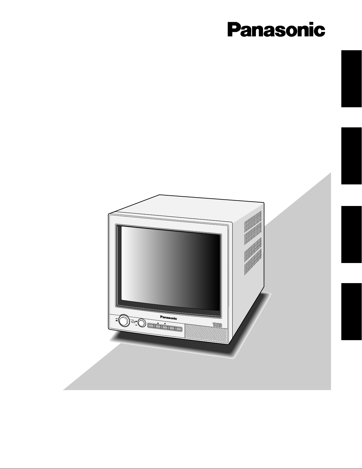
Model No. WV-CM1020
Video Monitor
Operating Instructions
ON
A
B
OFF
POWER INPUT
MENU
–+
AUDIO
Video Monitor WV-CM
ENGLISH
DEUTSCH
FRANÇAIS
ESPAÑOL
Page 2
2
ENGLISH VERSION
The lightning flash with arrowhead symbol, within an equilateral triangle, is
interned to alert the user to the presence
of uninsulated "dangerous voltage" within
the product's enclosure that may be of
sufficient magnitude to constitute a risk of
electric shock to persons.
The exclamation point within an equilateral triangle is intended to alert the user
to the presence of important operating
and maintenance (servicing) instructions
in the literature accompanying the appliance.
WARNING:
TO PREVENT FIRE OR ELECTRIC SHOCK HAZARD, DO NOT EXPOSE THIS APPLIANCE TO RAIN OR MOIS
TURE.
CAUTION:
TO REDUCE THE RISK OF ELECTRIC SHOCK,
DO NOT REMOVE COVER (OR BACK), NO USER
SERVICEABLE PARTS INSIDE.
REFER SERVICING TO QUALIFIED SERVICE
PERSONNEL.
CAUTION
RISK OF ELECTRIC SHOCK
DO NOT OPEN
FOR YOUR SAFETY PLEASE READ THE FOLLOWING TEXT CAREFULLY.
This appliance is supplied with a moulded three pin mains plug for your
safety and convenience.
A 5 amp fuse is fitted in this plug.
Should the fuse need to be replaced please ensure that the replacement
fuse has a rating of 5 amp and that it is approved by ASTA or BSI to
BS1362.
Check for the ASTA mark
H or the BSI mark G on the body of the
fuse.
If the plug contains a removable fuse cover you must ensure that it is
refitted when the fuse is replaced.
If you lose the fuse cover the plug must not be used until a replacement
cover is obtained.
A replacement fuse cover can be purchased from your local Panasonic
Dealer.
IF THE FITTED MOULDED PLUG IS UNSUITABLE FOR THE SOCKET OUTLET IN YOUR HOME THEN THE FUSE SHOULD BE
REMOVED AND THE PLUG CUT OFF AND DISPOSED OF SAFELY.
THERE IS A DANGER OF SEVERE ELECTRICAL SHOCK IF THE
CUT OFF PLUG IS INSERTED INTO ANY 10 AMP SOCKET.
If a new plug is to be fitted please observe the wiring code as shown
below.
If in any doubt please consult a qualified electrician.
WARNING: This apparatus must be earthed.
IMPORTANT
The wires in this mains lead are coloured in accordance with the following code.
Green-and-yellow: Earth
Blue: Neutral
Brown: Live
As the colours of the wire in the mains lead of this appliance may not
correspond with the coloured markings identifying the terminals in your
plug, proceed as follows.
The wire which is coloured green-and-yellow must be connected to
the terminal in the plug which is marked with the letter E or by the earth
symbol
I or coloured green or green-and-yellow.
The wire which is coloured blue must be connected to the terminal in
the plug which is marked with the letter N or coloured black.
The wire which is coloured brown
must be connected to the terminal in
the plug which is marked with the letter L or coloured red.
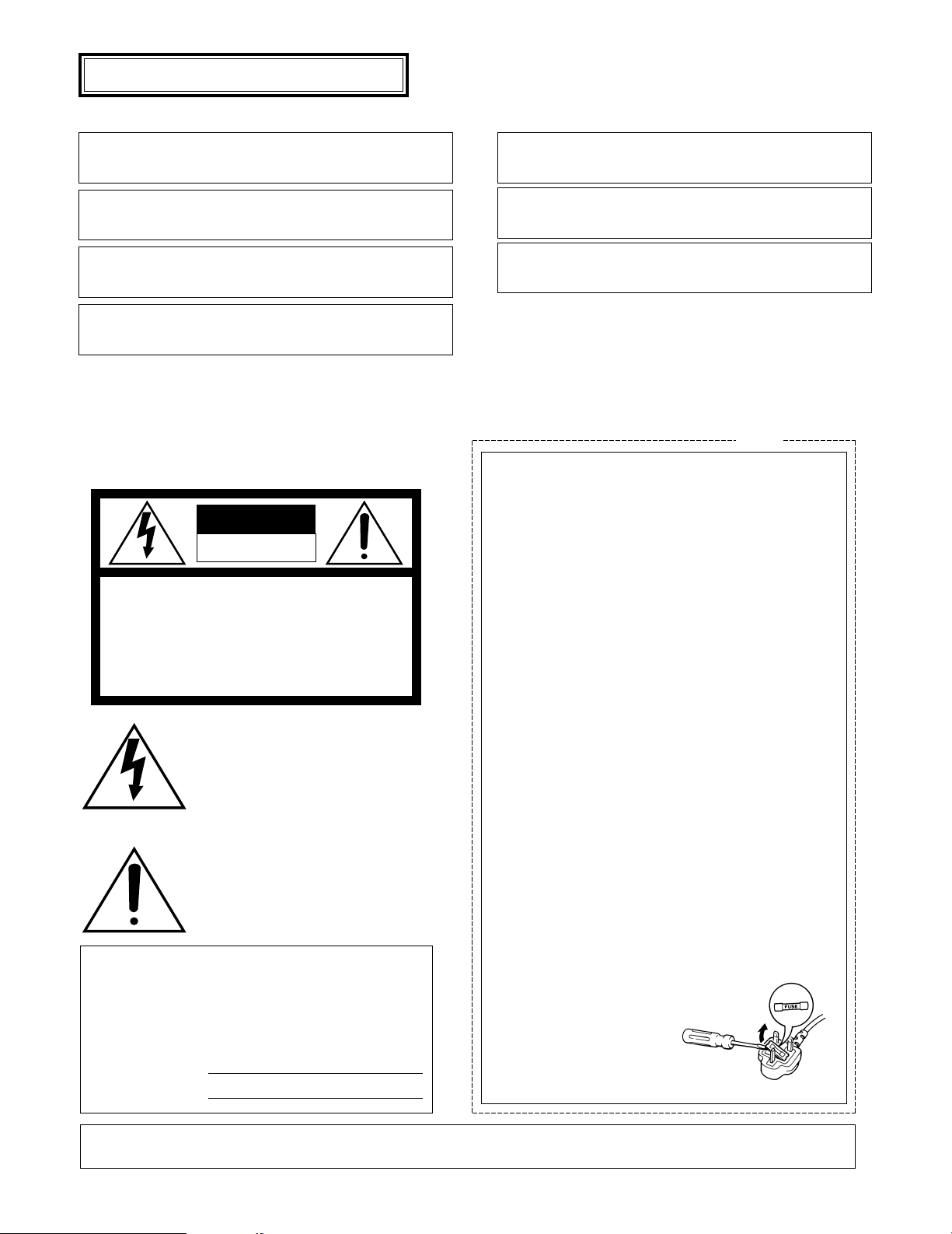
How to replace the fuse
Open the fuse compartment with
a screwdriver and replace the fuse
and fuse cover.
For U.K.
The serial number of this product may be found on the
rear of the unit.
You should note the serial number of this unit in the
space provided and retain this book as a permanent
record of your purchase to aid identification in the event
of theft.
Model No.
Serial No.
Wij verklaren als enige aansprakelijke, dat het product waarop deze
verklaring betrekking heeft, voldoet aan de volgende normen of andere
normatieve documenten, overeenkomstig de bepalingen van Richtlijnen
73/23/EEC en 89/336/EEC.
Vi erklærer os eneansvarlige for, at dette produkt, som denne
deklaration omhandler, er i overensstemmelse med standarder eller
andre normative dokumenter i følge bestemmelserne i direktivene
73/23/EEC og 89/336/EEC.
Vi deklarerar härmed värt fulla ansvar för att den produkt till vilken
denna deklaration hänvisar är i överensstämmelse med standarddokument, eller andra normativa dokument som framställs i EEC-direktiv nr.
73/23 och 89/336.
Ilmoitamme yksinomaisella vastuullamme, että tuote, jota tämä ilmoitus
koskee, noudattaa seuraavia standardeja tai muita ohjeellisia asiakirjoja,
jotka noudattavat direktiivien 73/23/EEC ja 89/336/EE. säädöksiä.
Vi erklærer oss alene ansvarlige for at produktet som denne erklæringen
gjelder for, er i overensstemmelse med følgende normer eller andre
normgivende dokumenter som følger bestemmelsene i direktivene
73/23/EEC og 89/336/EEC.
We declare under our sole responsibility that the product to which this
declaration relates is in conformity with the standards or other normative
documents following the provisions of Directives EEC/73/23 and
EEC/89/336.
Noi dichiariamo sotto nostra esclusiva responsabilità che il prodotto a
cui si riferisce la presente dichiarazione risulta conforme ai seguenti
standard o altri documenti normativi conformi alle disposizioni delle
direttive CEE/73/23 e CEE/89/336.
Page 3

3
CONTENTS
PREFACE ........................................................................................................................................................................................ 4
FEATURES ...................................................................................................................................................................................... 4
PRECAUTIONS ............................................................................................................................................................................... 4
MAJOR OPERATING CONTROLS AND THEIR FUNCTIONS ........................................................................................................ 5
CABLE INFORMATIONS ................................................................................................................................................................ 6
INSTALLATIONS ............................................................................................................................................................................ 6
SYSTEM CONNECTION ................................................................................................................................................................. 7
ADVANCED CONTROL OPERATION ............................................................................................................................................ 8
SPECIFICATIONS ........................................................................................................................................................................... 9
OPTIONAL ACCESSORY ............................................................................................................................................................... 9
ENGLISH
Page 4

4
The Panasonic‘s Video Monitor WV-CM1020 produces
sharp colour pictures and audio output.
PREF ACE
• Do not block the ventilation slots.
• Place the video monitor at least 5 cm (2 inches) apart
from the wall.
• Do not expose the monitor to water or moisture.
• Do not operate the monitor if it becomes wet.
• Take immediate action if ever the monitor becomes
wet. Turn power off and refer servicing to qualified service personnel. Moisture can damage the monitor and
also create the danger of electric shock.
• Do not drop metallic parts through slots. This action
could permanently damage the monitor. Turn power off
immediately and refer servicing to qualified service
personnel.
• Do not attempt to disassemble the monitor. To prevent
electric shock, do not remove screws or cover. There
are no user serviceable parts inside. Refer servicing to
qualified service personnel.
• Do not use the monitor beyond its temperature, humidity or power source ratings.
a) Ambient temperature must not range beyond
–10˚C - +50˚C (14˚F – 122˚F).
b) Avoid using the monitor when humidity is above
90 %.
c) The input power must be 220 - 240 V AC.
PRECAUTIONS
FEATURES
• Approx. 223 mm (8-3/4” inches) actual diagonal visual
size.
• A or B channel selectable for input and output signals.
• Looped through BNC connectors for video inputs and
outputs.
• Operations controlled by moving the cursor in the
setup menu.
• Automatic frequency control activated from setup
menu.
• Looped through RCA connectors for audio input and
output.
• Maximum 0.5 W speaker output.
• For mounting in optional 19” rack with adapter WVQ52AE (up to two monitors).
Page 5

5
MAJOR OPERATING CONTROLS AND THEIR FUNCTIONS
ON
A
B
OFF
POWER INPUT
MENU
– +
AUDIO
Video Monitor WV-CM
FOCUS
VIDEO B
IN
OUT
VIDEO AINAUDIO
IN
OUT OUT
AC IN
q u oi !5!0!1!2!3 !4w r t ye
q Power Switch (POWER, ON/OFF)
This is a push-push type switch which turns the power
of this monitor on and off.
Press once (switch remains down (;)) to turn on the
power of the monitor.
Press again (switch comes up (l)) to turn off the
power of the monitor.
Note: There may be a delay of several seconds until
the monitor display comes on.
w Power Indicator
Is on when the monitor‘s power is turned on.
e Input Signal Select Switch (INPUT A/B)
This is a push-push type switch which selects the signal input A or B.
Press once (switch remains down (;)) to select the
INPUT B signal.
Press again (switch comes up (l)) to select the
INPUT A signal.
r Menu Button (MENU)
Press to display the setup menu.
t Cursor Buttons (D, C)
Press these buttons to select a parameter by moving
the cursor up or down in the parameter rows.
y Increment/Decrement Buttons (AUDIO –, +)
• Setup screen adjustment (Menu displayed)
Press these buttons to adjust the level of an item
selected in the setup menu.
Note: If you select NORMAL SETTINGS in the Setup
menu, and press the Increment/Decrement button
(–) or (+), all menu parameters will be restored to
the factory default settings.
• Audio adjustment (Menu not displayed)
Press these buttons to increase or decrease the sound
volume.
u Focus Control (FOCUS)
This control adjusts the screen focus.
i Screen Control
This control is preset at the factory.
o Audio Input Connector (AUDIO IN)
For input of audio signal from an outboard device.
!0 Audio Output Connector (AUDIO OUT)
The audio input signal connected to the audio input
connector o is looped through to this connector.
Page 6

6
!1 Video A input Connector (VIDEO A IN)
For input of the PAL composite video signal from an
outboard device.
!2 Video A output Connector (VIDEO A OUT)
The video input signal connected to the video input
connector !1 is looped through to this connector and
terminated automatically.
!3 Video B input Connector (VIDEO B IN)
For input of the PAL composite video signal from an
outboard device.
■ Power Cable
1. Keep the Power Switch q in the OFF position during
installation.
2. Connect the Power Cord to a grounded electrical outlet.
■ Video Cable
1. Use RG-59/U (3C-2V), RG-6/U (5C-2V), RG-11/U (7C2V) or RG-15/U (10C-2V) coaxial cable.
2. Wiring Precautions:
• Do not bend a coaxial cable into a curve whose
radius is smaller than 10 times its diameter.
• Never crush or pinch the cable.
This will change the impedance of the cable and
cause poor picture quality.
Recommended maximum cable length
CABLE INFORMATION
!4 Video B output Connector (VIDEO B OUT)
The video input signal connected to the video input
connector !3 is looped through to this connector and
terminated automatically.
!5 AC Connector (AC IN)
Connector for AC power supply cord.
INSTALLATIONS
■ Mounting in the Rack
This monitor can be mounted in the rack as shown in the
figure. For more information, refer to the instructions of the
Rack Mount Bracket WV-Q52AE.
Rack Mount Screws
(Not provided)
Recommended
maximum
cable length
Cable
RG-59U
(3C-2V)
RG-6/U
(5C-2V)
RG-11/U
(7C-2V)
RG-15/U
(10C-2V)
250 m
(825 ft)
500 m
(1 650 ft)
600 m
(1 980 ft)
800 m
(2 650 ft)
P
O
W
E
R
IN
P
U
T
O
N
A
O
F
F
M
E
N
U
A
B
U
D
–+
V
id
e
o
M
o
n
it
o
r
IO
W
V
-
C
M
Page 7

7
■ Single Monitor Connection
● Connecting Cameras
1. Connect the Video Output terminal of the camera to the
Video Input Connector A or B of the monitor with a 75ohm coaxial cable.
Note: Keep the Power Switch in the OFF position before
connecting the camera.
● Connecting VTR
• Monitoring the Playback picture
Connect the Video Input terminal A or B of the monitor
to the Video Output Connector of the VTR with a 75ohm coaxial cable.
• Monitoring the sound
Connect the Audio Out Terminal of VTR to the Audio
Input Connector of the monitor.
● Multiple Monitor Connection
• Recording on the VTR
Connect the Video Output terminal A or B of the camera, to the Video Input Connector of the VTR with a 75ohm coaxial cable.
1. Connect the Video Output of the camera or the VTR to
the Video Input of monitor 1 with 75-ohm a coaxial
cable.
2. Connect the Video Output of the monitor 1 to the Video
Input of the monitor 2 with 75-ohm coaxial cable.
Notes:
• Automatic termination will not function if the con-
nections are not correct.
• Up to 10 monitors can be hooked up in this config-
uration before signal loss occurs. Total cable
length should not exceed 150 m (500 feet).
SYSTEM CONNECTION
TL
VIDEO OUT
VIDEO
IN
AUDIO
OUT
Camera
VTR
FOCUS
VIDEO B
IN
OUT
VIDEO AINAUDIO
IN
OUT OUT
AC IN
VIDEO OUT
FOCUS
VIDEO B
IN
OUT
VIDEO AINAUDIO
IN
OUT OUT
AC IN
VIDEO OUT
Monitor (1)
Monitor (2)
To another monitor
VIDEO IN
Camera
FOCUS
VIDEO B
IN
OUT
VIDEO AINAUDIO
IN
OUT OUT
AC IN
VIDEO OUT
Camera
Camera
VIDEO OUT
VIDEO OUT
FOCUS
VIDEO B
OUT
IN
VIDEO AINAUDIO
OUT OUT
IN
AC IN
Page 8

BRIGHT
8
Indicator
AFC
■ Displaying the Setup Menu
1. Press the power switch once (switch remains down (;)) to turn on the power of the monitor.
2. Power Indicator is on.
3. Select the input channel by pressing the input signal select switch.
Press the MENU button to open the setup menu.
It will close automatically if no operation takes place within about 3 seconds.
■ Adjustment
4. Move the cursor to LANGUAGE by pressing the (D) or (C) button.
5. Select the desired LANGUAGE parameter by pressing the (–) or (+) button. Pressing the button will toggle the language of
the setup menu as shown below.
6. Move the cursor to BRIGHT, CONTRAST, PICTURE, COLOUR or AFC by pressing the (D) or (C) button, then adjust the
level of the selected item by pressing the (–) or (+) button.
While the level of an item is being adjusted, the indicator displays the changed level as shown below.
ADVANCED CONTROL OPERATION
BRIGHT 0
CONTRAST 0
PICTURE 0
COLOUR 0
AFC SHORT
LANGUAGE ENGLISH
NORMAL SETTINGS
ENGLISH FRANÇAIS
+
–
DEUTSCH
Item Effect
CONTRAST
PICTURE
COLOUR
Darker Brighter
Less More
Soft
Sharp
Less More
Short Long
BRIGHT 20
CONTRAST 20
PICTURE 20
COLOUR 20
Page 9

9
BRIGHT 0
CONTRAST 0
PICTURE 0
COLOUR 0
AFC SHORT
LANGUAGE ENGLISH
NORMAL SETTINGS
– or +
BRIGHT -12
CONTRAST +8
PICTURE -16
COLOUR -6
AFC LONG
LANGUAGE ENGLISH
NORMAL SETTINGS
7. To reset the monitor to the default settings, move the cursor to NORMAL SETTINGS by pressing the (D) or (C) button.
Then press the (–) or (+) button to restore the factory default settings.
8. To exit the setup display, press the Menu button or wait for about 3 seconds until it closes automatically.
Power Source : 220 - 240 V AC, 50 Hz
Power Consumption : Approx. 47 W
Screen Size : 250 mm (9-13/16”) diagonal tube screen size, 90˚ deflection
223 mm (8-3/4”) diagonal actual visual size
Horizontal Resolution : 300 TV lines at center
Video Input : 1.0 V[p-p] composite/75 Ω, BNC with Auto Termination
Audio Input : –8 dB/Hi-z, RCA standard jack
Speaker Output : 0.5 W
Sweep Linearity : Horizontal: Less than 5 %
Vertical: Less than 5%
Sweep Geometry : Less than 2 %
Ambient Operating Humidity : Less than 90 %
Ambient Operating Temperature : –10˚C - +50˚C (14˚F – 122˚F)
Dimensions : 220(W) x 220 (H) x 309(D)mm [8-11/16”(W)x8-11/16”(H)x12-3/16”(D)]
Weight : 6.5
kg (14.3 lbs.)
Weights and dimensions shown are approximate.
Specifications are subject to change without notice.
SPECIFICATIONS
Rack Mount Bracket ........................................... WV-Q52AE
OPTIONAL ACCESSOR Y
Page 10

Matsushita Electric Industrial Co., Ltd.
Central P.O. Box 288, Osaka 530-91, Japan
N0999-1129 YWV8QA5238BN Printed in Japan
N 19 Gedruckt in Japan
Imprimé au Japon
Impreso en Japón
 Loading...