

Page 1
Before attempting to connect or operate this product,
please read these instructions carefully and save this manual for future use.
No model number suffix is shown in this manual.
(Lens: option)
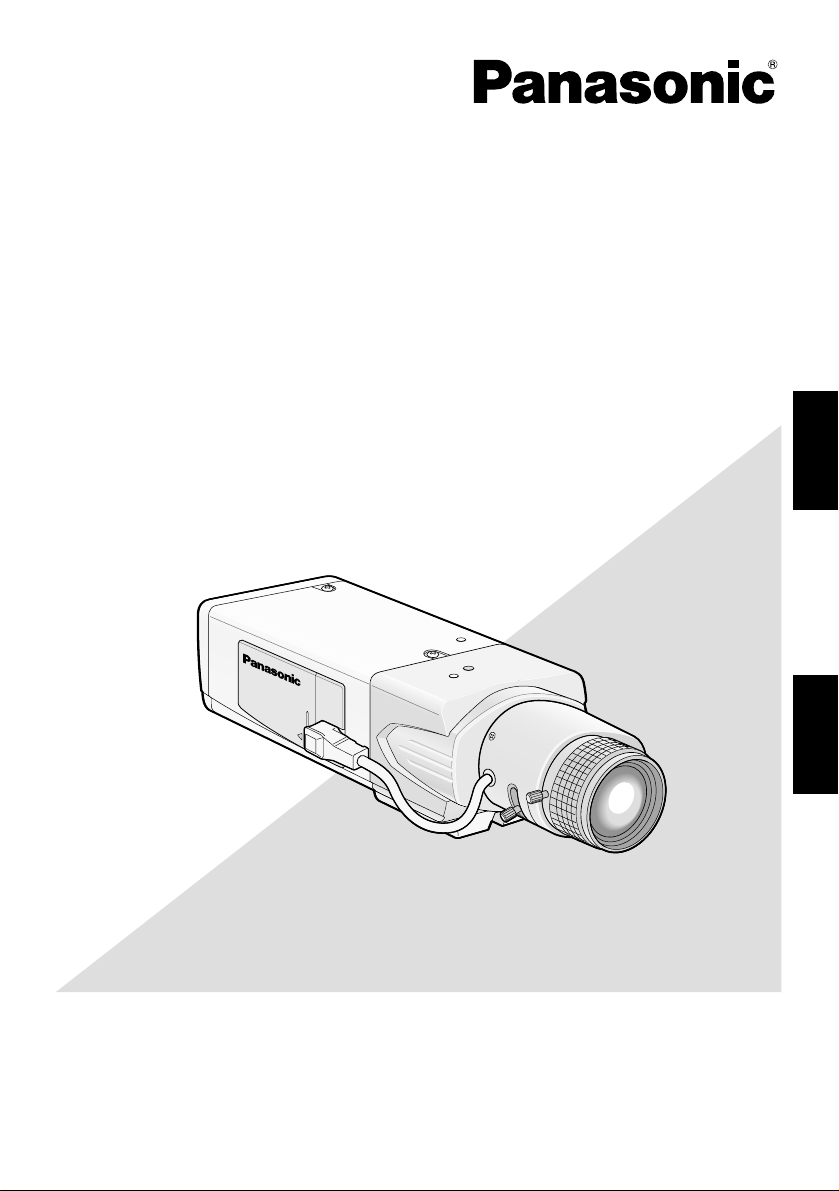
Color CCTV Cameras
Operating Instructions
Model Nos. WV-CL930
WV-CL934
ENGLISHFRANÇAIS
2X
TV LENS
WV-LZ80/2
6~12m
m
1:1.4
Page 2
2
ENGLISH VERSION
CAUTION: TO REDUCE THE RISK OF ELECTRIC SHOCK,
DO NOT REMOVE COVER (OR BACK).
NO USER-SERVICEABLE PARTS INSIDE.
REFER SERVICING TO QUALIFIED SERVICE PERSONNEL.
CAUTION
RISK OF ELECTRIC
SHOCK DO NOT OPEN
The lightning flash with arrowhead symbol, within an equilateral triangle, is intended to alert
the user to the presence of uninsulated "dangerous voltage"
within the product's enclosure
that may be of sufficient magnitude to constitute a risk of electric shock to persons.
The exclamation point within an
equilateral triangle is intended to
alert the user to the presence of
important operating and maintenance (servicing) instructions in
the literature accompanying the
appliance.
WARNING:
• This apparatus must be earthed.
• Apparatus shall be connected to a mains socket outlet with a protective earthing connection.
• The mains plug or an appliance coupler shall
remain readily operable.
• To prevent fire or electric shock hazard, do not
expose this apparatus to rain or moisture.
• The apparatus should not be exposed to dripping or splashing and that no objects filled with
liquids, such as vases, should be placed on the
apparatus.
• All work related to the installation of this product should be made by qualified service personnel or system installers.
• The connections should comply with local electrical code.
The serial number of this product may be found
on the surface of the unit.
You should note the model number and serial
number of this unit in the space provided and
retain this book as a permanent record of your
purchase to aid identification in the event of
theft.
Model No.
Serial No.
NOTE: This equipment has been tested and
found to comply with the limits for a Class A digital device, pursuant to Part 15 of the FCC Rules.
These limits are designed to provide reasonable
protection against harmful interference when the
equipment is operated in a commercial environment. This equipment generates, uses, and can
radiate radio frequency energy and, if not
installed and used in accordance with the instruction manual, may cause harmful interference to
radio communications.
Operation of this equipment in a residential area
is likely to cause harmful interference in which
case the user will be required to correct the interference at his own expense.
FCC Caution: To assure continued compliance,
(example - use only shielded interface cables
when connecting to computer or peripheral
devices). Any changes or modifications not
expressly approved by the party responsible for
compliance could void the user’s authority to
operate this equipment.
For U.S.A
For U.S.A
This Class A digital apparatus complies with
Canadian ICES-003.
For Canada
Power disconnection. Unit with or without ON-OFF
switches have power supplied to the unit whenever
the power cord is inserted into the power source;
however, the unit is operational only when the ONOFF switch is in the ON position. Unplug the power
cord to disconnect the main power for all units.
Page 3

3
CONTENTS
Important Safety Instructions ..................... 4
Limitation of Liability .................................. 5
Disclaimer of Warranty .............................. 5
Preface ...................................................... 6
Precautions ................................................ 7
Major Operating Controls and Their
Functions ................................................... 9
■ Side view ............................................. 9
■ Rear view ............................................. 9
Installations/Connections ........................... 11
Optional dedicated lens ........................... 11
Setting of external synchronization
switch ...................................................... 18
External terminal ..................................... 18
Setup Menus .............................................. 19
Setup menu list ........................................ 19
■ Basic operation .................................... 21
Camera Operation Setup [CAMERA
SETUP] ...................................................... 23
1. Camera title setting [CAMERA ID] ...... 23
2. Method of controlling quantity of light
[ALC/ELC] ........................................... 25
Backlight compensation ...................... 25
3. Electronic shutter setting
[SHUTTER] ......................................... 28
4. Gain control setting [AGC] ................... 29
5. Electronic sensitivity enhancement
setting [SENS UP] ............................... 30
6. Synchronization setting [SYNC] .......... 31
7. White balance setting [WHITE BAL] .... 35
8. Motion detector function setting
[MOTION DET] .................................... 36
9. Digital noise reduction function setting
[DNR] ................................................... 40
10. Image resolution setting
[RESOLUTION] ................................. 40
11. Settings in black-and-white mode
[BW MODE] ........................................40
12. Privacy zone setting [PRIVACY
ZONE] .............................................. 42
13. Image horizontal flip [MIRROR] ......... 43
14. Lens type setting [LENS-DRIVE] ....... 43
15. Image stabilizer setting
[STABILIZER] .................................... 44
Back focus setting [BACK-FOCUS
SETUP] ...................................................... 45
Special Menu Setup [SPECIAL SETUP] ... 47
Chroma level adjustment
[CHROMA GAIN] ..................................... 47
Aperture level adjustment [AP GAIN] ...... 47
Pedestal level adjustment [PEDESTAL] .. 47
Chroma phase level (hue)
adjustment [HUE] .................................... 48
Pixel compensation [PIX OFF] ................ 48
Communication configuration
[COMMUNICATION] ............................... 49
Default restoring [CAMERA RESET] ....... 49
Serial number viewing [SER.NO.] ........... 49
Language Selection
[LANGUAGE SETUP] ................................ 50
Shortcut Operation ..................................... 51
Troubleshooting ......................................... 52
Specifications ............................................. 54
Standard Accessories ................................ 55
ENGLISH
Page 4

4
Important Safety Instructions
1) Read these instructions.
2) Keep these instructions.
3) Heed all warnings.
4) Follow all instructions.
5) Do not use this apparatus near water.
6) Clean only with dry cloth.
7) Do not block any ventilation openings. Install in accordance with the manufacturer's
instructions.
8) Do not install near any heat sources such as radiators, heat registers, stoves, or other
apparatus (including amplifiers) that produce heat.
9) Do not defeat the safety purpose of the polarized or grounding-type plug. A polarized plug
has two blades with one wider than the other. A grounding type plug has two blades and a
third grounding prong. The wide blade or the third prong are provided for your safety. If the
provided plug does not fit into your outlet, consult an electrician for replacement of the
obsolete outlet.
10) Protect the power cord from being walked on or pinched particularly at plugs, convenience
receptacles, and the point where they exit from the apparatus.
11) Only use attachments/accessories specified by the manufacturer.
12) Use only with the cart, stand, tripod, bracket, or table specified by the manufacturer, or
sold with the apparatus. When a cart is used, use caution when moving the cart/apparatus
combination to avoid injury from tip-over.
13) Unplug this apparatus during lightning storms or when unused for long periods of time.
14) Refer all servicing to qualified service personnel. Servicing is required when the apparatus
has been damaged in any way, such as power-supply cord or plug is damaged, liquid has
been spilled or objects have fallen into the apparatus, the apparatus has been exposed to
rain or moisture, does not operate normally, or has been dropped.
S3125A
Page 5

5
Limitation of Liability
THIS PUBLICATION IS PROVIDED "AS IS"
WITHOUT WARRANTY OF ANY KIND,
EITHER EXPRESS OR IMPLIED, INCLUDING
BUT NOT LIMITED TO, THE IMPLIED WARRANTIES OF MERCHANTABILITY, FITNESS
FOR ANY PARTICULAR PURPOSE, OR
NON-INFRINGEMENT OF THE THIRD
PARTY'S RIGHT.
Disclaimer of Warranty
IN NO EVENT SHALL MATSUSHITA ELECTRIC INDUSTRIAL CO., LTD. BE LIABLE TO
ANY PARTY OR ANY PERSON, EXCEPT FOR
REPLACEMENT OR REASONABLE MAINTENANCE OF THE PRODUCT, FOR THE
CASES, INCLUDING BUT NOT LIMITED TO
BELOW:
(1) ANY DAMAGE AND LOSS, INCLUDING
WITHOUT LIMITATION, DIRECT OR
INDIRECT, SPECIAL, CONSEQUENTIAL
OR EXEMPLARY, ARISING OUT OF OR
RELATING TO THE PRODUCT;
(2) PERSONAL INJURY OR ANY DAMAGE
CAUSED BY INAPPROPRIATE USE OR
NEGLIGENT OPERATION OF THE USER;
(3) UNAUTHORIZED DISASSEMBLE,
REPAIR OR MODIFICATION OF THE
PRODUCT BY THE USER;
(4) INCONVENIENCE OR ANY LOSS ARIS-
ING WHEN IMAGES ARE NOT DISPLAYED, DUE TO ANY REASON OR
CAUSE INCLUDING ANY FAILURE OR
PROBLEM OF THE PRODUCT;
(5) ANY PROBLEM, CONSEQUENTIAL
INCONVENIENCE, OR LOSS OR DAMAGE, ARISING OUT OF THE SYSTEM
COMBINED BY THE DEVICES OF THIRD
PARTY;
(6) ANY CLAIM OR ACTION FOR DAM-
AGES, BROUGHT BY ANY PERSON OR
ORGANIZATION BEING A PHOTOGENIC SUBJECT, DUE TO VIOLATION
OF PRIVACY WITH THE RESULT OF
THAT SURVEILLANCE-CAMERA'S PICTURE, INCLUDING SAVED DATA, FOR
SOME REASON, BECOMES PUBLIC OR
IS USED FOR THE PURPOSE OTHER
THAN SURVEILLANCE.
THIS PUBLICATION COULD INCLUDE
TECHNICAL INACCURACIES OR TYPOGRAPHICAL ERRORS. CHANGES ARE
ADDED TO THE INFORMATION HEREIN, AT
ANY TIME, FOR THE IMPROVEMENTS OF
THIS PUBLICATION AND/OR THE CORRESPONDING PRODUCT (S).
Page 6

6
Preface
This product is a 1/2-inch type {1/2"} CCD color CCTV camera. Connection of this product to a
video monitor allows users to use this product as a monitoring camera. The main features are
described as follows:
Introduction of near-infrared CCD
This camera has the capacity to shoot pictures under the light source from the near-infrared
light region to the visible light region.
Auto back focus function (ABF) equipped
Moving the CCD inside the camera to an optimal position with the operation button of this unit
or the setup menu allows users to automatically adjust the back focus.
The back focus is adjustable with the setup menu through the system controller (option) even
after installation of this unit.
The auto back focus function also allows users to correct out of focus when changing between
color and black-and-white images.
High sensitivity achieved thanks to noise reduction function
As low as 0.09 lx (F1.4) has been accomplished for color images thanks to the introduction of
low noise circuit design.
Night monochrome image activation function equipped
No setting change is required at night because images automatically changes from the color
mode to the black-and-white mode at low illuminance.
Motion detector function equipped
If motion is observed in the monitor, the camera is covered with a cloth, a cap, or the like, or the
camera direction is changed during monitoring, an alarm signal is provided.
Note:
The motion detector function is not exclusively used for prevention of theft, fire, etc. We are
not responsible for any accidents or damages occurring in case.
Page 7
7
Precautions
This product has no power switch.
Power is supplied from an external 12 V DC/
24 V AC (WV-CL934) or 120 V AC (WVCL930) power-supply device. Refer to service personnel for how to turn on/off the
power.
To keep on using with stable performance
• Parts of this product may deteriorate and
it may shorten lifetime of this product
when using in locations subject to high
temperatures and high humidity. Do not
expose this product to direct heat
sources such as a heater.
• Use the product at temperature within
–10°C to +50°C {14°F to 122°F} and
humidity below 90 %. (When using this
product without turning the power off)
Do not rub the edges of metal parts with
your hand.
Failure to observe this may cause injury.
Do not attempt to disassemble this product.
To prevent electric shock, do not remove
screws or covers.
There are no user-serviceable parts inside.
Ask qualified service personnel for servicing.
Use this product for indoor use only.
Do not expose this product to direct sunlight
for hours and do not install the product near
a heater or an air conditioner. Otherwise, it
may cause deformation, discoloration and
malfunction. Keep this product away from
water.
Handle this product with care.
Do not abuse this product. Avoid striking,
shaking, etc. The product could be damaged
by improper handling or storage.
Cleaning this product body
Turn the power off when cleaning this product. Use a dry cloth to clean this product. Do
not use strong abrasive detergent when
cleaning this product. When the dirt is hard
to remove, use a mild detergent and wipe
gently. Then, wipe off the remaining detergent with a dry cloth.
Otherwise, it may cause discoloration. When
using a chemical cloth for cleaning, read the
caution provided with the chemical cloth
product.
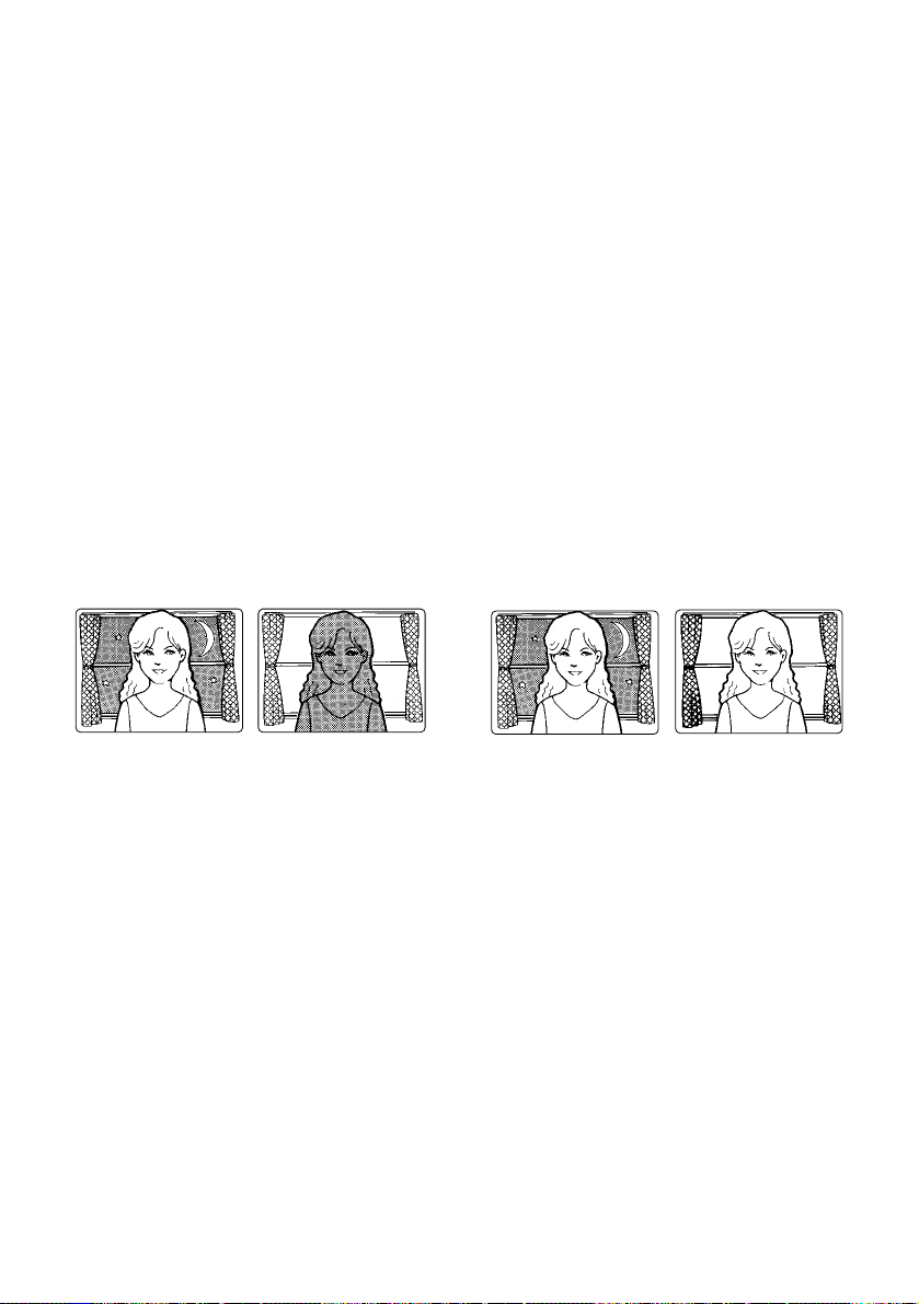
Noise on monitor
This product is equipped with a super sensitive CCD. Therefore, white dot noise may
appear on the monitor. This phenomenon is
not trouble.
Discoloration on the CCD color filter
When continuously shooting a bright light
source such as a spotlight, the color filter of
the CCD may have deteriorated and it may
cause discoloration. Even when changing the
fixed shooting direction after continuously
shooting a spotlight for a certain period, the
discoloration may remain.
Do not aim this product at strong light
sources.
A light source such as a spot light causes a
blooming (light bleeding) or a smear (vertical
lines).
Smear
Bright subject
Blooming
Page 8

8
Turn the circuit breaker off which supplies
this product with the power when abnormal conditions are encountered.
Avoid installing in the following locations.
• Locations where it may get wet from rain
or water splash
• Locations where a chemical agent is
used such as a swimming pool (not only
outdoor)
• Locations subject to steam and oil smoke
such as a kitchen
• Locations near flammable gas or vapor
• Locations where radiation or x-ray emissions are produced
• Locations subject to strong magnetic
field or radio waves
• Locations where corrosive gas is produced
• Locations where it may be damaged by
briny air such as seashores
• Locations where the temperature is not
within –10 °C to +50 °C {14°F to 122°F}.
• Locations subject to vibrations (This
product is not designed for on-vehicle
use.)
• Locations subject to condensation as the
result of severe changes in temperature
Installing place
Contact your dealer for assistance if you are
unsure of an appropriate place in your particular environment.
Make sure that the installation area is strong
enough to hold this product, such as a concrete ceiling.
Do not install this product in a humid or
dust-laden environment.
Otherwise, lifetime of the internal parts may
be shortened.
Be sure to remove this product if it is not
in use.
Radio interference
When this product is used near TV/radio
antenna, strong electric field or magnetic
field (near a motor or a transformer), images
may be distorted and noise sound may be
produced.
Mounting screws
Only the fixing screws are provided to fix this
product with the camera mounting base. It is
necessary to procure screws or bolts to
mount this product. Prepare them according
to the material and strength of the area where
this product is to be installed. The screws
and bolts must be tightened with an appropriate tightening torque according to the
material and strength of the installation area.
Do not operate this product beyond the
specified temperature, humidity or power
source ratings.
Use this product at temperatures within
–10 °C to +50 °C {14°F to 122°F}, and humidi-
ty below 90 %. The input power source is
12 V DC/24 V AC (WV-CL934) or 120 V AC
(WV-CL930).
Avoid connections during a lightning
storm.
Otherwise, an electric shock may be caused.
Page 9

9
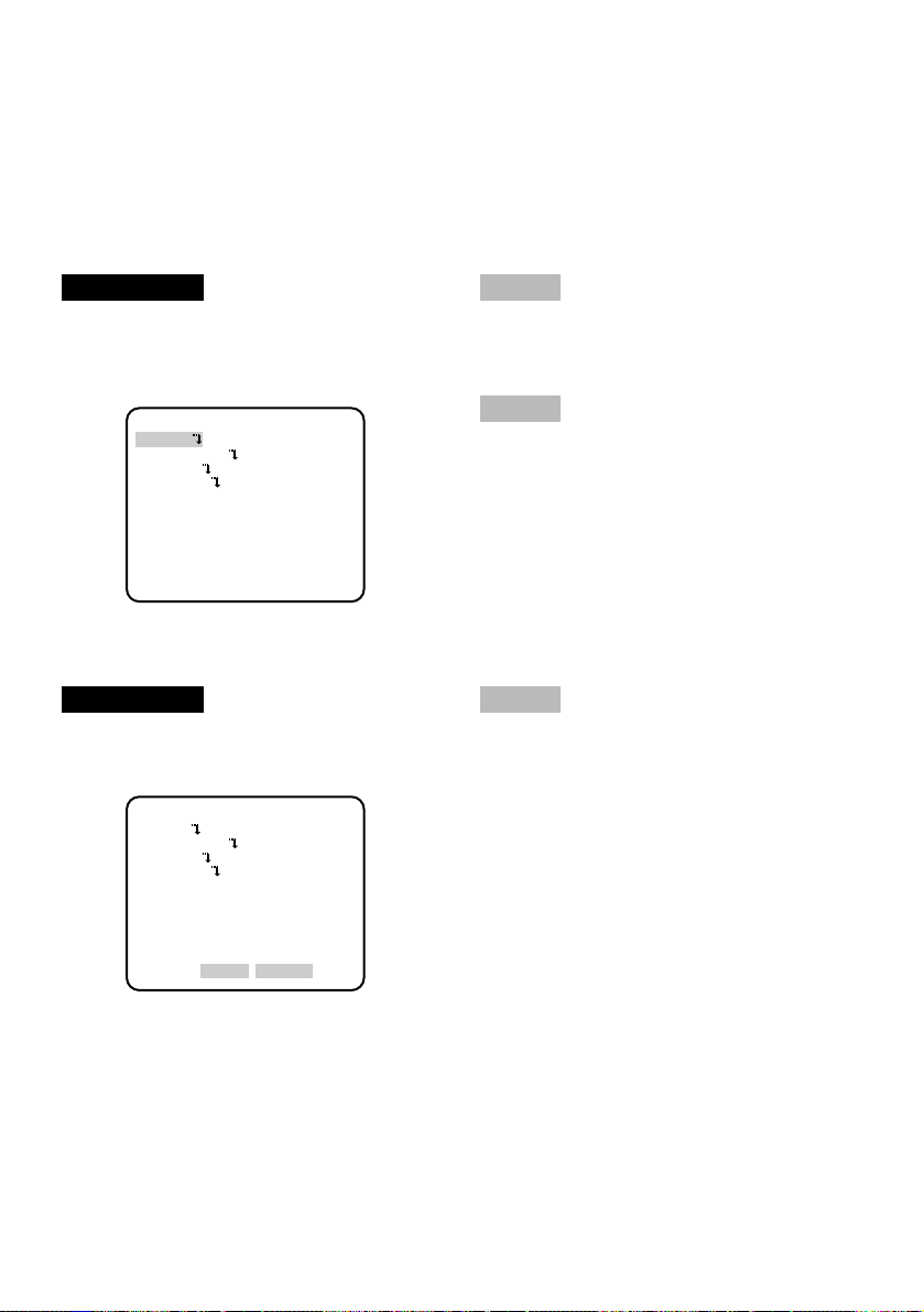
Major Operating Controls and Their Functions
AC 24V IN
DC 12V IN
GEN-LOCK VIDEO OUT
POWER
ALARM
2-N
1-L
DAY/
NIGHT
GND
GND
IN
OUT
<WV-CL930>
<WV-CL930/WV-CL934>
<WV-CL934>
Inside the side cover
(Slide the cover leftward to the lock position.)
(UP)
(LEFT)
(RIGHT)
(DOWN)
(SET)
FAR
ABF/MENU
Hi-Z
G /L75Ω
NEAR
120V ~ 60Hz
GEN-LOCK VIDEO OUT
POWER
ALARM
DAY/
NIGHT
GND
GND
IN
OUT
qwe
r
t
y
u
i
o
y
u
i
o
!1
!0 !2
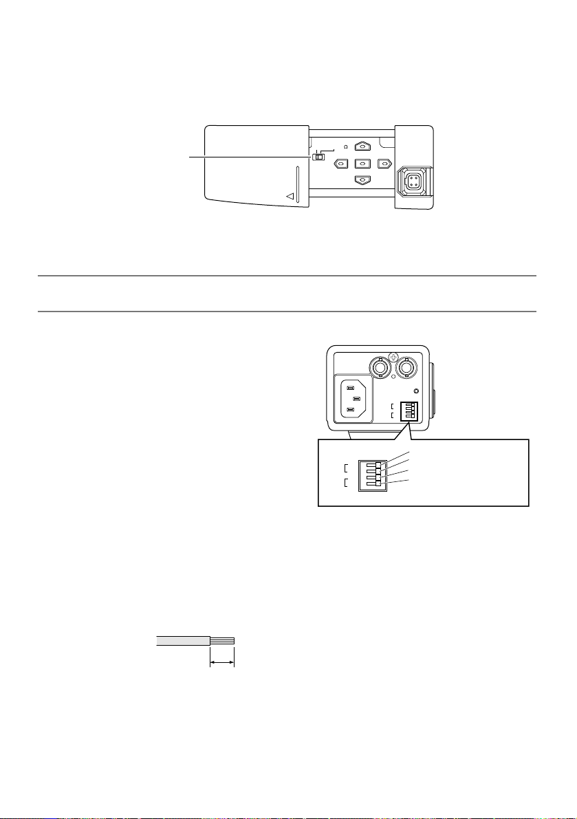
■ Side view
■ Rear view
Page 10

10
q Side cover
When the external synchronization switch
or operation buttons are used, the side
cover is slid leftward to the lock position.
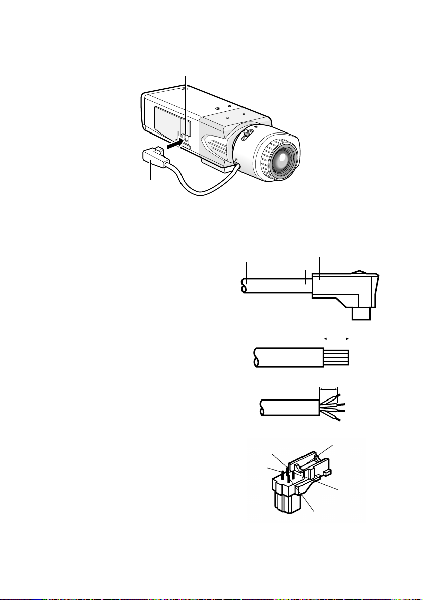
w ALC lens connector
The ALC connector is connected to this
ALC lens connector. If the connector
shape is a different type, replace the
connector with the ALC connector
(accessory).
e Tripod socket
This socket is used to mount the camera
mounting base (option). The tripod socket can be mounted on either top or bottom of the camera head.
(Tripod socket hole: 1/4-20 UNC for tripod)
r External synchronization switch
(☞ page 18)
t Operation buttons
This buttons are used to perform various
settings in the setup menu.
J: Up button (UP)
K: Down button (DOWN)
L: Left button (LEFT), NEAR
M: Right button (RIGHT), FAR
I: Setting button (SET), ABF/MENU
y External synchronization input con-
nector
(☞ page 14)
u Video output connector
The video output cable is connected to
this video output connector.
i Power indicator
This indicator lights up when the power is
on.
o External terminal
(☞ page 18)
!0 Power connector (only for WV-CL930)
The included power cord is connected to
this power connector.
!1 Signal ground terminal
(only for WV-CL934)
The ground wire is connected to this terminal.
!2 AC/DC power terminal
(only for WV-CL934)
The power supply of 24 V AC or 12 V DC
is connected to this terminal.
Page 11
11
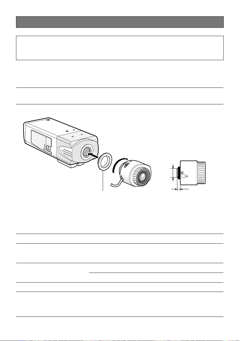
Installations/Connections
z Rotate the lens (option) clockwise slowly to mount the lens.
Important:
• For use of C-mount lens, use the C-mount adaptor (accessory).
Optional dedicated lens
Lens type Model No.
1/2-inch type {1/2"} variable
focal lens
1/2-inch type {1/2"} zoom lenses
2 x varifocal
6 x Motorized
10 x Motorized
WV-LZ80/2
WV-LZ81/6A
WV-LZ81/10
Caution:
• ONLY CONNECT WV-CL934 TO 24 V AC OR 12 V DC CLASS 2 POWER SUPPLY.
• Be sure to connect the grounding lead to the GND terminal.
Note:
It is recommended to use a lens whose F number is F1.2 or greater.
When using a lens whose F number is smaller than F1.2, sharpness of image may be
diminished.
ø20 mm {ø3/4"} or less
C-mount adaptor (accessory)
* Required for use of C-mount lens
C mount: 4.5 mm {5/32"} or less
CS mount: 4.5 mm {5/32"} or less
Page 12
12
x Connect the ALC connector (accessory) of the lens to the ALC lens connector of
the camera.
If an auto iris lens with a different shaped connector is used, replace the connector with the
ALC connector (accessory).
q Cut off the lens cable from the connector.
w Strip the end 8 mm {5/16"} of the lens cable
outside cover, and then, remove each cover
of the core wires by 2 mm {1/16"}.
e Solder the core wires to the pins of the ALC
connector securely.
Pin 1: Red (Power)
Pin 2: Not used
Pin 3: White (Video)
Pin 4: Black (Shield)
ALC lens connector
ALC connector
Lens cable
Lens cable
Pin 3
Pin 1
Cut here
ALC connector
Approx. 8 mm
Approx. 6 mm
Rib
Pin 4
Pin 2
Page 13
13
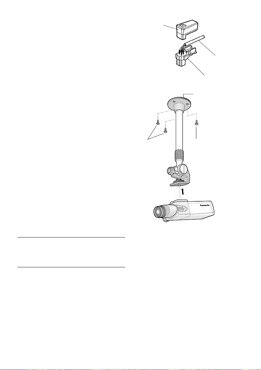
r Put the cover on the ALC connector so
that the lens cable is secured to the rib.
c Secure the camera mounting base
(option) to an installation position,
and mount the camera on the base.
• The mounting method of the camera
mounting base varies depending on the
material of the installation position.
Do not use wood screws or nails to
secure the camera mounting base.
• Steel products:
Secured with bolts and nuts
• Concrete wall:
Secured with anchor bolts or AY plug
bolts (M6 or M8) manufactured by
Matsushita Electric Works, Ltd.
(Recommended tightening torque
(M6): 5.0 N·m {3.7 lbf·ft}, recommended tightening torque (M8): 6.2
N·m {4.6 lbf·ft}
• The mounting conditions of the camera
mounting base are described as follows:
Important:
• If the total weight of the camera and lens
exceeds 1 kg, use a housing to take
measures against camera drop.
Cover
Lens cable
ALC connector
Screws
(locally procured)
Camera mounting
base (option)
Screw
(locally procured)
Page 14
14
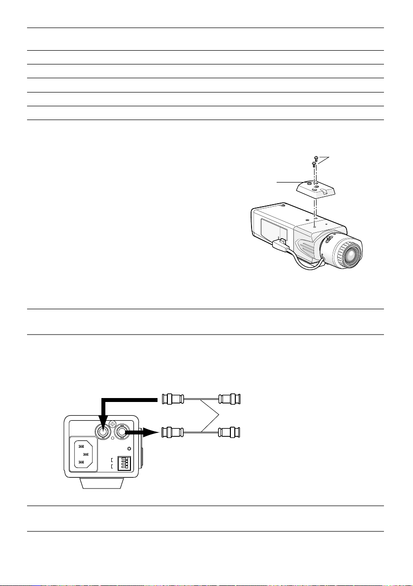
v Establish the connection of a coaxial cable (locally procured).
Important:
• Be sure to turn off the power of each device before connection.
Connect a coaxial cable (locally procured) to the video output connector. If the synchronizing signal input is provided from an external device, connect another coaxial cable to the
external synchronization input connector.
Important:
• Be sure to secure the coaxial cable connectors.
• When the tripod socket is mounted on
the top of the camera, be sure to use the
screws that were removed from the tripod socket. Use of longer or shorter
screws may cause drop or damage.
(Recommended tightening torque: 0.39
N·m {0.29 lbf·ft})
Applicable
mounting base
Installation
position
Recommend-
ed screw
Screw
quantity
Minimum pull-out
strength (per 1 screw)
WV-7011On ceiling M6 4 pieces 196 N {44 lbf}
WV-7010 M8 3 pieces 196 N {44 lbf}
WV-7012 M6 3 pieces 196 N {44 lbf}
WV-831On wall M8 4 pieces 921 N {207 lbf}
WV-7013 M6 3 pieces 2.25 kN {505 lbf}
For some applicable mounting bases, "A" is attached to the model number. The mounting conditions are the same even for the A-attached models.
Screws
Tripod socket hole:
1/4-20 UNC
Tripod socket
From external synchronization source
(VBS/VS)
Coaxial cables (locally procured)
120V ~ 60Hz
GEN-LOCK VIDEO OUT
POWER
GND
ALARM
OUT
GND
DAY/
NIGHT
IN
(This illustration represents WV-CL930.)
To video input (CAMERA IN)
Page 15
15
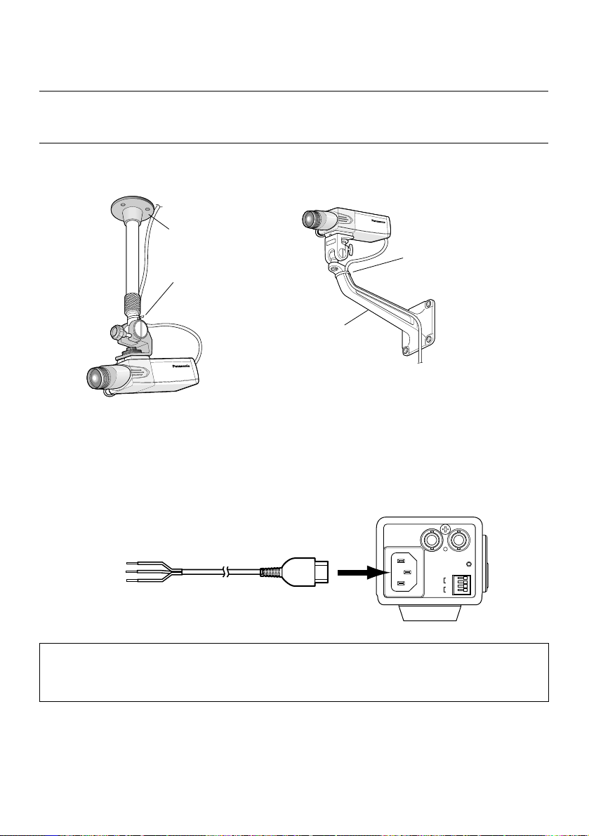
b Use a cable tie (locally procured) to attach the coaxial cable to the camera
mounting base.
Important:
• The cable tie shall be made of metallic or durable material to be strong enough because
the tie plays the role of camera drop prevention measures in case.
n Connect the power cord and turn on the power.
WV-CL930
Connect between the power connector on the rear side of the camera and a plug socket
with the supplied power cord.
Caution:
The camera shall be connected with cord set with plug.
Plug for respective country shall be mounted on the Power cord by a qualified electrical.
<Installation sample on a ceiling> <Installation sample on a wall>
Camera mounting
base (option)
The cable shall be tied to
the camera mounting
base.
Camera mounting base
(option)
The cable shall be tied to
the camera mounting
base.
120V ~ 50Hz
GEN-LOCK VIDEO OUT
POWER
GND
ALARM
OUT
GND
DAY/
NIGHT
IN
120 V AC,
60 Hz
Power cord (accessory)
Page 16

16
WV-CL934
Select either 24 V AC or 12 V DC for
power supply and connect the power
supply to the AC/DC power terminal.
m Adjust the camera angle by loosening the screw of the camera mounting base
while viewing the video monitor.
Be sure to loosen the screw of the camera mounting base when the camera angle is
adjusted. If the camera angle is changed when the screw is tight, excessive force is
applied to the camera mounting base and camera, and accordingly they may be damaged. Be sure to tighten the screw securely after camera angle adjustment.
, Adjust the focus.
When an auto iris lens is used, the originally adjusted focus may be slightly off depending
on the iris state resulting from the focal depth of the lens. In such a case, open the iris by
darkening the subject as much as possible and adjust the focus, and the focus-off state
can be prevented.
Use of "ABF" of "BACK-FOCUS SETUP" in the setup menu (☞ page 45) allows users to
adjust the focus optimally in the range of the capability to automatically follow the variation
in illuminance. (Note: The adjusted focal point is not necessarily the same as the optimal
focal point at the specified illuminance.)
• The out-of-focus level in the near-infrared light region may be higher than that in the
visible light region.
Setting "C/L ←→ B/W" of "BACK-FOCUS SETUP" to "AUTO" or "PRESET" in the setup
menu allows users to adjust the focus in both the near-infrared light and visible light
regions. (The variation in illuminance is not followed after focus adjustment.)
How to use varifocal lens/zoom lens
• Reset the back focus position to the CS mount default position before the back focus
adjustment. (Press the right and left buttons among the operation buttons simultaneously,
or move the cursor to "MANUAL-ADJ" of "BACK-FOCUS SETUP" in the setup menu and
press the right and left buttons simultaneously after pressing the setting button.)
• Be aware that the adjustment method varies with varifocal lens or zoom lens models. For
further information, refer to the operating instructions for the lens to be used.
Caution:
To prevent fire or electric shock hazard, use a UL listed cable (VW-1, style
1007) for the 24 V AC or 12 V DC
Input Terminal.
AC 24V IN
DC 12V IN
GEN-LOCK VIDEO OUT
1-L
2-N
ALARM
DAY/
NIGHT
POWER
GND
OUT
GND
IN
+
–
12 V DC or 24 V AC
Page 17

17
Notes:
• The adjustment procedure for general varifocal lenses is described as follows: For further
information, refer to the operating instructions for the lens to be used.
1. Display a subject that exists as far as possible (10 m or more recommended) to adjust
the back focus.
2. For 8-, or 10-fold magnification lenses, adjust the back focus after setting the zoom to
the WIDE end and setting the focus to the FAR end.
For 2-, or 3-fold magnification lenses, adjust the back focus after setting the zoom to
the TELE end and setting the focus to the FAR end.
3. Adjust the view angle and focus coarsely by adjusting the zoom and focus of the lens
to center a subject in the screen, and then perform the main adjustment of the back
focus (☞ pages 17 and 45).
• When a non-Panasonic lens that has an extended range for lens focusing is used, adjust
the back focus after setting the focus to a position at a short distance from the FAR end in
Step 2 described above. If adjustment is performed in the extended range, appropriate
adjustment cannot be obtained.
How to use fixed focus lens
• For a fixed focus lens with focus adjustment, adjust the back focus after setting the focus of
the lens to the FAR end.
. Adjusts the back focus.
Use the operation buttons (☞ page 9) for this operation.
The back focus is also adjustable in the setup menu. Refer to page 45 for how to operate
and detailed explanation.
q Press the setting button after adjusting the view angle while viewing the video monitor.
w The focus position indicator is displayed
in the lower part of the screen, and the
back focus is automatically adjusted.
e To perform fine adjustment of the back
focus after automatic back focus adjustment, use the right or left button.
Notes:
• No operation for more than 10 seconds automatically clears the focus position indicator.
• Pressing the right and left buttons simultaneously resets the back focus position to the CS
mount default position.
NEAR FAR
.........|..........
INDICATOR XXXX
Page 18
18
Setting of external synchronization switch
When an external synchronizing signal input is provided to the external synchronization input
connector on the rear side of the camera for loop through, select "Hi-Z". To terminate the connector, select "G/L 75 Ω". Select "G/L 75 Ω" for the normal situation, too.
External terminal
Important:
• Be sure to turn off the power of each device before connection.
Alarm output
Output specification: Open collector output
(max. voltage: 16 V DC)
Off: 2 to 4 V DC, internally pulled up
On: Output voltage 1 V DC or less (max. drive
current: 100 mA)
Color/black-and-white input
Input specification: No-voltage make contact
input (3 to 5 V DC, internally pulled up)
Color: Open or 3 to 5 V DC
Black and white: Make contact with GND
(required drive current: 0.2 mA or more)
* When color input or black-and-white input is
enabled, set the black-and-white switching, "BW MODE" to "EXT". (☞ page 40)
* When an external device is connected, exercise care to avoid exceeding the rating.
* Applicable wire: AWG22-AWG28, solid wire/stranded wire
Strip the end 9 to 10 mm {30" to 33"} of the wire and insert it.
G /L75
External synchronization switch
Hi-Z
NEAR
(LEFT)
ABF/MENU
(SET)
(UP)
FAR
(RIGHT)
(DOWN)
120V ~ 60Hz
GEN-LOCK VIDEO OUT
GND
ALARM
OUT
GND
DAY/
NIGHT
ALARM
DAY/
NIGHT
GND
OUT
GND
IN
* The external terminal is the same between
WV-CL930 and WV-CL934.
WV-CL930
POWER
IN
GND
ALARM (alarm output)
GND
DAY/NIGHT
(color input/BW input)
9 to 10 mm {30" to 33"}
Page 19

19
Setup Menus
Performing each setting item in the setup menu should be completed in advance to use this
unit. Perform the settings for each item in accordance with the conditions of the camera shooting area.
The following is an example of setup procedure when LANGUAGE is set to ENGLISH.
Setup menu list
CAMERA SETUP Performs the camera operation settings.
CAMERA ID Specifies the camera title. "CAMERA ID" creates the
camera title that indicates the camera location and
other information about the camera with alphanumeric, symbol, and displays on the screen.
ALC/ELC Selects the method of controlling the quantity of light
in accordance with the lens to be used.
SHUTTER Specifies the electronic shutter speed.
AGC Specifies gain adjustment.
SENS UP Specifies electronic sensitivity enhancement.
SYNC Specifies the synchronization type.
WHITE BAL Specifies white balance adjustment.
MOTION DET Selects the motion detector mode.
DNR Selects the level of the digital noise reduction function.
RESOLUTION Selects the level of image resolution.
BW MODE Performs each setting regarding the black-and-white
mode such as switching between color and black-
and-white images.
PRIVACY ZONE Hides undesired portions in the camera shooting area.
MIRROR Flips images horizontally.
LENS-DRIVE Selects the drive control type in accordance with the
lens to be used.
STABILIZER Decides whether or not to enable the image stabilizer.
BACK-FOCUS SETUP Selects the back focus setting type and performs fine
adjustment.
23
25
28
29
30
31
35
36
40
40
40
42
43
43
44
45
Setup item Description
Reference
pages
Page 20

20
SPECIAL SETUP
CHROMA GAIN Adjusts the chroma level.
AP GAIN Adjusts the aperture level.
PEDESTAL Adjusts the pedestal level.
HUE Adjusts the chroma phase (hue) level.
PIX OFF Corrects image defect such as flaws.
COMMUNICATION Performs the communication setting of the system with
a receiver into which this unit is integrated.
CAMERA RESET Restores the settings in the setup menu to the default
settings.
SER.NO. Displays the serial number of this unit.
LANGUAGE SETUP Selects a language to be used in the setup menu.
Setup item Description
Reference
pages
47
47
47
48
48
49
49
49
50
Page 21
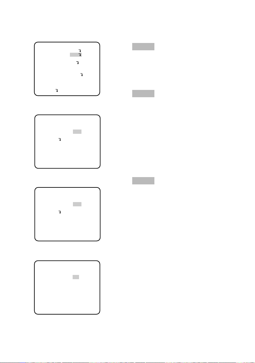
21
Screenshot 2
The setup mode changes to "ENABLE", and
the setup menu becomes ready to be set.
Step 3
Move the cursor to the item to be set, and
press the setting button.
Screenshot 1
Hold down the setting button for approx. 2
seconds to call up the top screen of the
setup menu.
Step 1
Press the up button or the down button to
move the cursor to "END".
Step 2
Press the right button to move the cursor to
"SETUP", and press the setting button to
change the setup mode from "DISABLE" to
"ENABLE".
■ Basic operation
The description below explains how to operate the setup menu basically.
The operations in the setup menu are performed with the operation buttons (☞ page 9) after
calling up the setup menu on the connected video monitor.
The operations in the setup menu can also be performed through the system controller (option).
MODEL WV-CL930 SERIES
CAMERA
BACK-FOCUS
SPECIAL
LANGUAGE
END SETUP DISABLE
MODEL WV-CL930 SERIES
CAMERA
BACK-FOCUS
SPECIAL
LANGUAGE
END SETUP ENABLE
Page 22
22
Screenshot 3
The selected setup screen in the setup menu
appears on the screen.
Notes:
• If the top screen of the setup menu is
called up while a camera image is displayed, the setup mode is always "DISABLE" to prevent operation errors. To
perform settings in the setup menu,
change the setup mode to "ENABLE".
• The cursor is a reversely highlighted
part.
Step 4
Perform the settings for each item.
• Selection of setting item:
Press the up button or down button to
move the cursor.
• Change of settings:
Press the right button or left button.
• Display of advanced setup screen:
Press the setting button when "O" is
attached to the target setting item.
• Return to previous setup screen:
Move the cursor to "RET" and press the
setting button.
• Return to top screen:
Move the cursor to "TOP" and press the
setting button.
Step5
To return to the camera image screen, move
the cursor to "END" and press the setting button.
**CAMERA SETUP** 1/2
CAMERA ID OFF
ALC/ELC ALC
SHUTTER OFF
AGC ON
SENS UP OFF
SYNC INT
WHITE BAL ATW1
MOTION DET OFF
DNR HIGH
RESOLUTION HIGH
BW MODE
**CAMERA SETUP** 2/2
PRIVACY ZONE OFF
MIRROR OFF
LENS-DRIVE DC
STABILIZER OFF
RET TOP END
Page 23
23
Camera Operation Setup [CAMERA SETUP]
The following describes the camera operation settings. The following settings are performed on
the "CAMERA SETUP" screen through the top screen. Refer to page 21 for how to call up the
screen.
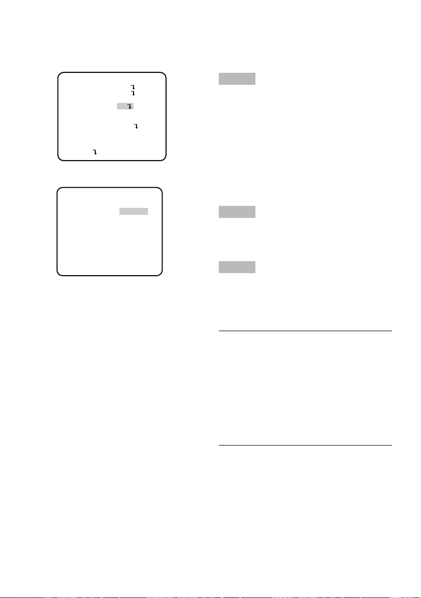
1. Camera title setting [CAMERA ID]
This item specifies the camera title. The camera title that indicates the camera location and
other information about the camera is created with alphanumeric characters and symbol, and
displayed on the screen. The camera title is named with up to 16 characters. Follow the procedure below to specify the camera title.
Step 1
Set "CAMERA ID" to "ON" and press the setting button.
→ The title creation screen appears.
Step 2
Move the cursor to the target item with use of
the up, down, right, and left buttons, and
press the setting button to enter the character.
→ The entered characters are displayed in
the editing area.
"CAMERA SETUP" screen Title creation screen Display positioning screen
w
r
y
i
!0
**CAMERA SETUP** 1/2
CAMERA ID OFF
q
ALC/ELC ALC
SHUTTER OFF
e
AGC ON
SENS UP OFF
t
SYNC INT
WHITE BAL ATW1
u
MOTION DET OFF
DNR HIGH
o
RESOLUTION HIGH
BW MODE
!1
!3
!5
**CAMERA SETUP** 2/2
PRIVACY ZONE OFF
!2
MIRROR OFF
LENS-DRIVE DC
!4
STABILIZER OFF
RET TOP END
**CAMERA SETUP** 1/2
CAMERA ID OFF
ALC/ELC ALC
SHUTTER OFF
AGC ON
SENS UP OFF
SYNC INT
WHITE BAL ATW1
MOTION DET OFF
DNR HIGH
RESOLUTION HIGH
BW MODE
CAMERA ID
0123456789
ABCDEFGHIJKLM
NOPQRSTUVWXYZ
().,'":;&#!?=
+-*/%$
SPACE POSI
RET TOP END RESET
................
FLOOR 1
Editing area
Page 24

24
<Character entry>
• To revise a character, move the cursor to
the arrow (↑) in the editing area, move
the cursor (↑) to the character to be
revised with use of the right and left buttons, and enter a correct character.
• To enter a blank, move the cursor to
"SPACE" and press the setting button.
• To delete all the entered characters,
move the cursor to "RESET" and press
the setting button.
Step 3
Move the cursor to "POSI" and press the setting button after title entry.
→ The display positioning screen appears.
Step 4
Use the up, down, right, and left buttons to
decide the title position and press the setting
button.
→ The camera title and title position are
specified.
Page 25
25
2. Method of controlling quantity of light [ALC/ELC]
The method of controlling the quantity of light is selected from the following in accordance with
the lens to be used.
ALC (default): Adjusts the iris of the lens in accordance with the brightness of a subject. This
selection is suitable for use of an auto iris lens (ALC lens).
ALC+: Controls the quantity of light with a combination of the electronic shutter and auto iris.
This selection is suitable at shooting a bright subject such as an outdoor subject with auto
iris lens. Be aware that flicker may occur when a subject is under fluorescent lighting.
ELC: Fixes the iris of the lens to a set value. This selection is suitable for use of a lens with fixed
iris or manual iris.
Backlight compensation
• If a subject has a bright light such as a spotlight in its background, the subject appears
shadowy because the camera adjusts the iris in accordance with the bright area.
• To eliminate this phenomenon, masking bright areas allows users to perform backlight
compensation to hide bright areas.
• Backlight compensation has two modes: One is the PRESET ON mode for automatic compensation after sensing the light conditions on the camera side, the other is PRESET OFF
mode for specifying the sensing area manually.
Nighttime
Nighttime
Daytime
Daytime
[No backlight compensation performed] [Backlight compensation performed]
Page 26
26
PRESET mode setting
Step 1
Move the cursor to "ALC", "ALC+", or "ELC" of
"ALC/ELC" and press the setting button.
→ The "ALC CONT", "ALC+CONT" or "ELC
CONT" screen appears.
Step 2
Move the cursor to "PRESET" and use the
right or left button to select "ON" or "OFF".
ON: Automatically performs backlight com-
pensation.
OFF: Performs backlight compensation after
specifying the compensation area.
When "OFF" is selected, "MASK SET"
appears on the "ALC CONT", "ALC+
CONT" or "ELC CONT" screen. (☞ page
27)
Step 3
To change the video output level (image contrast), move the cursor to "LEVEL" and adjust
the level with use of the right or left button.
"CAMERA SETUP" screen
"ALC CONT" screen
"ELC CONT" screen
"ALC+CONT" screen
**CAMERA SETUP** 1/2
CAMERA ID OFF
ALC/ELC ALC
SHUTTER OFF
AGC ON
SENS UP OFF
SYNC INT
WHITE BAL ATW1
MOTION DET OFF
DNR HIGH
RESOLUTION HIGH
BW MODE
**ALC CONT**
BACK LIGHT COMP
PRESET OFF
PEAK MODE OFF
MASK SET
LEVEL
- +
RET TOP END
...|...128
**ALC+CONT**
BACK LIGHT COMP
PRESET OFF
PEAK MODE OFF
MASK SET
LEVEL
- +
RET TOP END
...|...128
**ELC CONT**
BACK LIGHT COMP
PRESET ON
PEAK MODE OFF
LEVEL
- +
RET TOP END
...|...128
Page 27
27
Sensing area setting for backlight compensation
If backlight compensation does not function desirably in the PRESET ON mode, use the PRESET OFF mode, mask too bright areas manually and perform backlight compensation.
**ALC CONT**
BACK LIGHT COMP
PRESET OFF
PEAK MODE OFF
MASK SET
LEVEL
...|...128
- +
RET TOP END
**ELC CONT**
BACK LIGHT COMP
PRESET OFF
PEAK MODE OFF
MASK SET
LEVEL
...|...128
- +
RET TOP END
"ALC CONT" screen
"ELC CONT" screen
Mask setting screen
Step 1
Move the cursor to "PRESET" and use left or
right button to select "OFF".
Step 2
Move the cursor to "MASK SET" and press
the setting button to call up the mask screen.
The mask setting screen shows 48-split
areas and blinks the top and far left split
area.
Step 3
Mask bright areas in the background.
q Move the blinking portion to the area to
be masked with use of the right or left
button.
w Press the setting button to mask the
area. When the blinking portion is present on the masked area, the masked
area is displayed with horizontal stripes
and white alternately.
When the blinking portion is present on
other areas, the masked area becomes
white.
e Repeat the operation w described
above until masking is completed, and
hold down the setting button for more
than 2 seconds to resume the previous
screen.
To cancel the masking, move the blinking
portion to the masked area and press the
setting button.
Step 4
To change the video output level (image contrast), move the cursor to "LEVEL" and adjust
the level with use of the right or left button.
"ALC+CONT" screen
**ALC+CONT**
BACK LIGHT COMP
PRESET OFF
PEAK MODE OFF
MASK SET
LEVEL
- +
RET TOP END
...|...128
Page 28

28
Flare compensation mode
If a lens flare is undesirable, move the cursor to "PEAK MODE" and use right or left button to
select "ON".
ON: Performs flare compensation.
OFF (default): Does not perform flare compensation.
3. Electronic shutter setting [SHUTTER]
The variation in electronic shutter speed allows users to perform the following.
• Increased shutter speed prevents blurring fast-moving subjects.
The electronic shutter speed is selectable from the following:
OFF (1/60) (default), 1/120, 1/250, 1/500, 1/1 000, 1/2 000, 1/4 000, and 1/10 000
Notes:
• When "ALC/ELC" is set to "ELC" or "ALC+" (☞ page 25), the shutter setting cannot be per-
formed. "OFF (1/60)" is automatically selected.
• If the controller, WV-CU254 or WV-CU204 is used, SW LED and the status of "SHUTTER"
are not correctly displayed.
Page 29
29
Step 1
Move the cursor to "AGC" and use right or left
button to select "ON" or "OFF".
ON (default): Automatically increases the
gain to make the screen brighter when
the illuminance of the subject becomes
darker. The maximum value is adjustable.
OFF: Does not increase the gain. (The nor-
mal image remains.)
Step 2
Move the cursor to "ON" and press the setting button to call up the "AGC MAX" screen.
Step 3
Move the cursor to "LEVEL". The cursor is
reversely highlighted.
Move the cursor horizontally to adjust the
gain with use of the right or left button.
Notes:
• Change in the level of "AGC MAX" causes change in the level of the input signal
that enables electronic sensitivity
enhancement when "SENS UP" is set to
AUTO and also change in the level of the
input signal that activates black-andwhite mode.
• If noise is undesirable, adjust the level of
"AGC MAX".
"CAMERA SETUP" screen
"AGC MAX" screen
4. Gain control setting [AGC]
**CAMERA SETUP** 1/2
CAMERA ID OFF
ALC/ELC ALC
SHUTTER OFF
AGC ON
SENS UP OFF
SYNC INT
WHITE BAL ATW1
MOTION DET OFF
DNR HIGH
RESOLUTION HIGH
BW MODE
** AGC MAX **
LEVEL ...|...128
- +
RET TOP END
Page 30

30
5. Electronic sensitivity enhancement setting [SENS UP]
Use of the electronic sensitivity enhancement function increases the quantity of light stored on
the CCD, and accordingly the image becomes brighter. The magnification is unchanged for
selection of FIX, and the magnification is changeable in accordance with the illuminance of a
subject for selection of AUTO. The magnification of the electronic sensitivity is selectable from
the following.
OFF (default)/X2 AUTO/X4 AUTO/X6 AUTO/X10 AUTO/X16 AUTO/X32 AUTO/X2 FIX/
X4 FIX/X6 FIX/X10 FIX/X16 FIX/X32 FIX/X64 FIX/X128 FIX
Notes:
• When the magnification of "SENS UP" is increased, the screen becomes coarser, more
whitish, or more flawed. However, this phenomenon is normal.
• The status display of the system device does not show "X64 FIX" and "X128 FIX" of "SENS
UP". In such cases, "X32 FIX" is shown.
• If the controller, WV-CU254 or WV-CU204 is used, SW LED and the status of "SENS UP" are
not correctly displayed.
Page 31

31
6. Synchronization setting [SYNC]
This unit supports the following 5 types of synchronization methods, and one of the following is
selected.
The order of descriptions below indicates the order of priorities.
q Multiplexed vertical drive signal (VD2)
w Power supply synchronization (LL)
* Synchronization is performed on the basis of the power supply frequency.
e Composite color video signal or black burst signal (VBS)
r Monochrome composite video signal or composite synchronizing signal (VS)
t Internal synchronization (INT) (default)
Input of a multiplexed vertical drive signal (VD2) automatically switches to the VD2 synchronization even if the camera is set to other than the VD2 synchronization method.
The set item displays are shown in the chart below with accordance with a synchronization signal input.
* These items are switchable with use of the right or left button.
When LL, VBS, or VS is selected, power supply synchronizing phase, genlock horizontal
phase, subcarrier phase, and others can be set up. (☞ pages 32 - 34)
Note:
When "INT" is selected, do not provide synchronization signals to the external synchronizing input connector on the rear side of the camera.
Power supply
frequency [Hz]
Synchronization signal input
VD2 VBS VS
Menu display
60
–
b
X
–X
b
–XX
VBS ↔ LL*
VS ↔ LL*
INT ↔ LL*
Page 32

32
Adjustment of phase in power supply synchronization mode (LL)
The adjusting video signal of the camera and the criterial external synchronizing input signal
are connected to a 2-input oscilloscope and the phase is adjusted.
Note:
Movement of the camera or presence of a spike noise in the power line may cause vertical
phase change. In such a case, adjust the phase again.
Follow the procedure in the next page to adjust the phase.
"CAMERA SETUP" screen
"SYNC" screen
Step 1
Set "SYNC" to "LL" and press the setting button.
→ The "SYNC" screen appears.
Step 2
Connect the video output signal and external
synchronizing input signal of the camera to a
2-input oscilloscope, and move the cursor to
"COARSE".
Step 3
Adjust the oscilloscope to the vertical rate,
and extend the vertical synchronizing part of
the oscilloscope.
Move the cursor horizontally to adjust the vertical phase with use of the right or left button.
The phase can be adjusted in 16 steps by
22.5 degrees.
1 (1--16) : 0 °/2 (1--16) : 22.5 °/ ...../16 (1--16)
: 337.5 °
Step 4
Move the cursor to "FINE", and move the cursor horizontally with use of the right or left
button to adjust both vertical phases.
**CAMERA SETUP** 1/2
CAMERA ID OFF
ALC/ELC ALC
SHUTTER OFF
AGC ON
SENS UP OFF
SYNC INT
WHITE BAL ATW1
MOTION DET OFF
DNR HIGH
RESOLUTION HIGH
BW MODE
**SYNC**
V PHASE
COARSE 1(1--16)
FINE
- +
RET TOP END
...|...128
Page 33

33
Step 1
Provide a VBS signal to the external synchronizing input connector on the rear side of the
camera.
→ The "SYNC" setting automatically
changes to "EXT (VBS)".
Step 2
Move the cursor to "EXT (VBS)" and press the
setting button.
→ The "SYNC" screen appears.
Step 3
Connect the video output signal and external
synchronizing input signal of the camera to a
2-input oscilloscope, and move the cursor to
"H PHASE".
Step 4
Adjust the oscilloscope to the horizontal rate,
and extend the horizontal synchronizing part
of the oscilloscope.
"SYNC" screen
Move the cursor horizontally to adjust the
horizontal phase with use of the right or left
button.
Adjustable range: 0 to –2.0 µs
Step 5
Move the cursor to "SC COARSE" (subcarrier
coarse adjustment), and use the following 4
steps to match the real color of the subject
with the color of the effect output signal (program output video signal) of the special
effect device (SEG) with use of right or left
button.
1 (1--4) : 0 °/2 (1--4) : 90 °/3 (1--4) : 180°/
4 (1--4) : 270 °
Step 6
Move the cursor to "SC FINE" (subcarrier fine
adjustment), and move the cursor horizontally with use of the right or left button to match
the real color of the subject with the color of
the program output video signal.
Notes:
• When the cursor moves to the right end
"+" position, the cursor moves to the left
end "-" position. At the time, the setting
value of "SC COARSE" is incremented by
1, and adjustment is continuously performed.
• Holding down the right or left button for
more than 1 second increases the cursor
moving speed.
• To achieve high precision adjustment,
provide the video signal of the camera
and program output signal to a vector
chromaticity indicator to compare the
macro phases of both signals.
"CAMERA SETUP" screen
Adjustment of phase in VBS genlock mode (VBS)
The adjusting video signal of the camera and the criterial external synchronizing input signal
are connected to a 2-input oscilloscope and the phase is adjusted. Follow the procedure below
to adjust the phase.
**CAMERA SETUP** 1/2
CAMERA ID OFF
ALC/ELC ALC
SHUTTER OFF
AGC ON
SENS UP OFF
SYNC INT
WHITE BAL ATW1
MOTION DET OFF
DNR HIGH
RESOLUTION HIGH
BW MODE
**SYNC**
H PHASE
- +
SC COARSE 1(1--4)
SC FINE
- +
RET TOP END
...|...128
...|...128
Page 34

34
Adjustment of phase in VS genlock mode (VS)
The adjusting video signal of the camera and the criterial external synchronizing input signal
are connected to a 2-input oscilloscope and the phase is adjusted. Follow the procedure below
to adjust the phase.
"CAMERA SETUP" screen
"SYNC" screen
Step 1
Provide a VS signal to the external synchronizing input connector on the rear side of the
camera.
→ The "SYNC" setting automatically
changes to "EXT (VS)".
Step 2
Move the cursor to "EXT (VS)" and press the
setting button.
→ The "SYNC" screen appears.
Step 3
Connect the video output signal and external
synchronizing input signal of the camera to a
2-input oscilloscope, and move the cursor to
"H PHASE".
Step 4
Adjust the oscilloscope to the horizontal rate,
and extend the horizontal synchronizing part
of the oscilloscope.
Move the cursor horizontally to adjust the
horizontal phase with use of the right or left
button.
Adjustable range: 0 to –2.0 µs
**CAMERA SETUP** 1/2
CAMERA ID OFF
ALC/ELC ALC
SHUTTER OFF
AGC ON
SENS UP OFF
SYNC INT
WHITE BAL ATW1
MOTION DET OFF
DNR HIGH
RESOLUTION HIGH
BW MODE
**SYNC**
H PHASE
- +
RET TOP END
...|...128
Page 35

35
7. White balance setting [WHITE BAL]
The white balance adjustment is selectable from the following.
ATW1 (default): Activates the automatic color temperature tracking mode. The camera contin-
uously measures the color temperature of the light source and automatically adjusts the
white balance. Manual fine adjustment is also enabled after automatic white balance setting. (☞ page 36)
The adjustment of the color temperature ranges from approx. 2 700 K to 6 000 K. If the situation meets one of the following or other, color may not be accurately reproduced.
• The subject is mostly highly-colored.
• The photographic atmosphere is under the bright blue sky or at nightfall.
• The illumination of the light illuminating the subject is low.
ATW2: Activates the sodium lamp automatic color temperature tracking mode. The camera
automatically achieves an optimal white balance under the sodium lamp.
The adjustment of the color temperature ranges from approx. 2 000 K to 6 000 K.
AWC: Activates the automatic white balance control mode. This adjustment is suitable for a
location where a light source is stable. The adjustment of the color temperature ranges
from approx. 2 000 K to 10 000 K. When "AWC" is selected, the operation to adjust the
white balance is required.
When "AWC" is selected, follow the steps below to adjust the white balance.
"CAMERA SETUP" screen
Step 3
Press the right button to select "AWC".
Refer to the next page for fine adjustment of
the white balance.
Note:
The adjustment of the color temperature
ranges from approx. 2 000 K to 10 000 K.
If the correct range is out of this adjustment range or lighting directed to a subject is too dark, the white balance may
not completely adjusted. In such a case,
"PUSH SW" stays reversely highlighted.
Step 1
Set "WHITE BAL" to "AWC" and press the left
button to change to "AWC → PUSH SW".
Step 2
Press the setting button and adjust the white
balance.
"PUSH SW" is reversely highlighted during
adjustment. When the reversely highlighted
display is restored, the white balance adjustment is completed.
**CAMERA SETUP** 1/2
CAMERA ID OFF
ALC/ELC ALC
SHUTTER OFF
AGC ON
SENS UP OFF
SYNC INT
WHITE BAL AWC
MOTION DET OFF
DNR HIGH
RESOLUTION HIGH
BW MODE
Page 36

36
8. Motion detector function setting [MOTION DET]
The motion detector function is set. Either MODE1 or MODE2 is selected. When MODE1 is
selected, the detailed settings such as settings of the detection sensitivity and detection area
are required. The detection area can be specified and checked in the demonstration mode.
MODE1: Provides an alarm signal when a motion is detected.
MODE2: Provides an alarm signal when the camera is covered or the camera direction is
changed.
OFF (default): Disables the motion detector function.
Description about motion detector function (MODE1)
This function split a screen into 48 blocks, detects brightness change in each block, and provides an alarm signal when a change (motion) is observed in the image of the shooting area.
This function allows users to record the camera image on a recording device when an alarm
sounds.
Manual fine adjustment of white balance
The white balance is manually fine adjusted after white balance automatically adjustment in the
automatic color temperature tracking mode (ATW) or automatic white balance control mode
(AWC).
Follow the procedure below for white balance fine adjustment.
Step 1
Set "WHITE BAL" to "ATW1", "ATW2" or "AWC"
and press the setting button.
→ The fine adjustment screen appears.
Step 2
Move the cursor to "R" and "B" and use the
right or left button to fine adjust the level for
each. "R" represents red and "B" represents
blue. When the level indicator moves in the
"+" direction, the color becomes deeper, and
when the level indicator moves in the "-"
direction, the color becomes lighter.
**CAMERA SETUP** 1/2
CAMERA ID OFF
ALC/ELC ALC
SHUTTER OFF
AGC ON
SENS UP OFF
SYNC INT
WHITE BAL ATW1
MOTION DET OFF
DNR HIGH
RESOLUTION HIGH
BW MODE
**ATW1**
R
...|...128
- +
B
...|...128
- +
RET TOP END
"CAMERA SETUP" screen
Fine adjustment screen
Page 37

37
Detection condition
Subject size: A moving subject needs to be equal to or larger than 1/48 of the screen at "STA-
BILIZER OFF".
Subject contrast: The contrast ratio between the background and moving subject needs to be
equal to or larger than 5 % (at maximum sensitivity).
Subject moving speed: The passing time for a subject to move from the end to the other end
of the screen needs to be equal to or larger than 0.8 seconds (at 5 % of contrast ratio). A
subject moving faster than the description above is undetectable.
Note:
The larger the contrast ratio (difference between brightness and darkness) becomes, the
less the limitation on the size and moving speed of a subject becomes.
Demonstration mode
The brightness change in each of 48-split blocks is detected, and the mask is covered on the
block where the change in the average brightness exceeds the specified detection sensitivity
level.
The adjustment of the detection sensitivity level and the setting of the detection areas are
repeated to obtain an optimal state on the basis of the results in the demonstration mode.
Description about motion detector function (MODE2)
This function provides an alarm signal when a change in the state of a subject occurs by covering the camera with a cloth, a cap, or others, or by changing the camera direction largely.
Important:
• A change in the state of a subject may not be detected in the following cases:
• When only a part of the lens is hidden, or the cover is transparent,
• When the subjects are similar between before and after changing the camera direction.
• False detection may occur in the following cases:
• When a change in brightness is significant such as turning on and off a light,
• When the traffic volume including people and cars is high.
Page 38

38
Advanced settings about motion detector function (MODE1)
The description below specifies the sensitivity level and detection area of the motion detector
(MODE1).
To perform mask setting, set the image stabilizer, i.e. "STABILIZER" to "OFF". (☞ page 44)
"MODE 1" screen
Mask setting screen
"CAMERA SETUP" screen
Step 1
Set "MOTION DET" to "MODE1" and press the
setting button.
→ The "MODE1" screen appears.
Step 2
Move the cursor to "MASK SET" and press
the setting button.
→ The mask setting screen appears.
Step 3
Perform mask setting. The operation procedure is the same as the masking operation in
the process of Sensing area setting for backlight compensation. (☞ page 27)
Step 4
Hold down the setting button for approx.
more than 2 seconds after completion of
masking.
→ The "MODE1" screen appears again.
Step 5
Move the cursor to "ALARM", and decide
whether or not to provide an alarm signal in
the demonstration mode with use of "ON" or
"OFF".
ON: Provides an alarm signal output in the
demonstration mode, and allows users to
check the operation on the monitor when
a motion is detection.
OFF (default): Provides no alarm signal out-
put in the demonstration mode.
**CAMERA SETUP** 1/2
CAMERA ID OFF
ALC/ELC ALC
SHUTTER OFF
AGC ON
SENS UP OFF
SYNC INT
WHITE BAL ATW1
MOTION DET OFF
DNR HIGH
RESOLUTION HIGH
BW MODE
**MODE1**
LEVEL
- +
DWELL TIME 2S
DISPLAY MODE
ALARM OFF
MASK SET
RET TOP END
...|...128
Page 39

39
Step 6
Move the cursor to "DISPLAY MODE" and press the setting button.
→ The demonstration mode is implemented, and the blocks on which significant brightness
change was detected blink.
Step 7
Press the setting button.
→ The demonstration mode is terminated, and "MODE1" screen appears again.
Step 8
Move the cursor to "LEVEL" and use the right or left button to adjust the detection sensitivity
level. When the level indicator moves in the "+" direction, the level becomes higher. When the
level indicator moves in the "–" direction, the level becomes lower.
Repeat from Step 6 to Step 8 to obtain an optimal level.
Step 9
Move the cursor to "DWELL TIME" and select an alarm detection skipping time from the following:
2S (default)/5S/10S/30S (S: Second)
Selection of an alarm detection skipping time disables the detection of an alarm until a lapse of
a specified time after detecting an alarm once.
Important:
• When a curtain swaying in the wind is detected, use the masking function to exclude the
curtain from the detection area.
• When the noise level is high under low illuminance lighting resulting in malfunction,
decrease the sensitivity (LEVEL). When the illuminance of a subject changes abruptly, e.g.
caused by car headlights or turning on and off a light, false detection may occur.
• Approximately 0.2-second delay exists between detection of a change (motion) in image
with this unit and alarm signal output. When the setup menu is displayed, an alarm output
is not provided. (The case that "ALARM" is set to ON in the demonstration mode is excluded.)
• Selection of "ON" for the motion detector function causes a malfunction with a device that
uses a VCR time code because an alarm data output is provided during blanking. In such
a case, set the motion detector function to "OFF".
• The motion detector function is not exclusively used for prevention of theft, fire, etc. We are
not responsible for any accidents or damages occurring in case.
Page 40

40
9. Digital noise reduction function setting [DNR]
The digital noise reduction function reduces noise automatically under the condition of low illuminance. The effect level of the noise reduction function is selectable from the following:
LOW: Low level of noise reduction (small residual image)
MID: Medium level of noise reduction (medium residual image)
HIGH (default): High level of noise reduction (large residual image)
10. Image resolution setting [RESOLUTION]
A resolution of camera images is selectable from the following:
NORMAL: Horizontal resolution of 480 TV lines or more
HIGH (default): Horizontal resolution of 540 TV lines typ.
Note:
When the electronic sensitivity enhancement function, "SENS UP", is activated under the
condition that "HIGH" is selected, noise may increase.
11. Settings in black-and-white mode [BW MODE]
The settings regarding the black-and-white mode are performed.
Follow the procedure below for settings regarding the black-and-white mode.
"CAMERA SETUP" screen "BW MODE" screen "BW MODE" screen
Step 1
Move the cursor to "BW MODE" and press
the setting button.
→ The "BW MODE" screen appears.
Step 2
Move the cursor to "BW" and select the
black-and-white control from the following:
AUTO1: Automatically toggles between color
and black-and-white images in accordance with the screen brightness (illuminance). The black-and-white mode is
selected for dark images, and the color
mode is selected for bright images.
AUTO2: Uses a near-infrared light source at
nighttime.
EXT: Is selected to control switching
between color and black-and-white
images after connecting an external
device to the external terminal (DAY/
NIGHT). (☞ page 18)
**CAMERA SETUP** 1/2
CAMERA ID OFF
ALC/ELC ALC
SHUTTER OFF
AGC ON
SENS UP OFF
SYNC INT
WHITE BAL ATW1
MOTION DET OFF
DNR HIGH
RESOLUTION HIGH
BW MODE
**BW MODE**
BW OFF
BURST(BW) ON
RET TOP END
**BW MODE**
BW AUTO1
LEVEL HIGH
DURATION TIME .|
S L
BURST(BW) ON
RET TOP END
..
Page 41

41
ON: Displays black-and-white images.
OFF (default): Displays color images.
Note:
If a subject is always moving or the
screen is occupied with a uniform color,
brightness determination may be not performed successfully because the brightness is merely determined by information
from the CCD image sensor. When
"AUTO2" is selected, the wave length of
the light source shall be 800 nm or
longer.
Step 3
Move the cursor to "LEVEL" and select a
brightness level at which switching between
color and black-and-white images is performed from the following:
LOW: Switches from color to black-and-white
images when the ambient brightness
(illuminance) of the camera is approx.
0.1 lx or less. (when the AGC MAX level
is set to the top end.)
HIGH (default): Switches from color to black-
and-white images when the ambient
brightness (illuminance) of the camera is
approx. 0.2 lx or less. (when the AGC
MAX level is set to the top end.)
Step 4
Move the cursor to "DURATION TIME" and
select a time for switching between color and
black-and-white images from the following:
(Default: 30 seconds)
10 sec.- 30 sec.- 60 sec.- 300 sec.
(S) (L)
Step 5
Move the cursor to "BURST (BW)", and
decide whether or not to provide a burst signal output in the black-and-white mode with
use of "ON" or "OFF".
ON (default): Provides a burst signal output.
OFF: Does not provide any burst signal out-
put.
Notes:
• The auto back focus function also allows
users to correct out of focus when
changing between color and black-andwhite images. (☞ page 45)
• Images may not be displayed appropriately without burst signals when camera
images are displayed in the black-andwhite mode depending on a monitor or
VCR model to be used. In such a case,
set the burst signal output to "ON".
Page 42

42
12. Privacy zone setting [PRIVACY ZONE]
When undesired portions in the camera shooting area (on the screen) exist, those portions (privacy zone) are hidden.
ON (1): Grays the zone.
ON (2): Mosaics the zone.
OFF (default): Displays the zone normally.
Up to 8 portions can be specified for the privacy zone. Follow the procedure below for privacy
zone setting.
Note:
The privacy zone function is disabled at initializing the unit, i.e. right after turning on the
power.
"CAMERA SETUP" screen Zone number selection screen Zone setting screen
Step 1
Move the cursor to "PRIVACY ZONE", select
"ON (1)" or "ON (2)", and press the setting
button.
→ The zone number selection screen
appears.
Step 2
Use the right or left button to select the target
zone number after ascertaining that the cursor is present on "1" of "1/8" located at the
right side of "ZONE NUMBER". When a zone
number is marked with "*" at its right side, the
zone with the number is already set to the
privacy zone.
Step 3
Press the setting button after zone number
selection.
→ The zone setting screen appears.
Notes:
• When a zone number that is already set
to the privacy zone in Step 3 is selected,
the image of the zone is displayed in the
zone frame on the zone setting screen.
Performing Step 4 and Step 5 clears the
setting zone and implements new zone
setting.
• To cancel the zone setting, move the cursor to "DEL" and press the setting button.
The zone setting is canceled.
**CAMERA SETUP** 2/2
PRIVACY ZONE OFF
MIRROR OFF
LENS-DRIVE DC
STABILIZER OFF
RET TOP END
**ZONE NUMBER 1 /8**
RET TOP END
**ZONE NUMBER 1 /8**
POSITION PUSH SW
SCALE PUSH SW
SET DEL
RET TOP END
Page 43

43
Step 4
Move the cursor to "POSITION" and press the setting button.
Step 5
Use the up, down, right, and left buttons to decide the zone position and press the setting button.
→ The zone position is determined.
Step 6
Move the cursor to "SCALE" and use the up, down, right and left buttons to adjust the zone
frame size. The up and down buttons decide the vertical size, and the right and left buttons
decide the horizontal size. Press the setting button after the zone frame size setting.
Step 7
Move the cursor to "SET" and press the setting button.
→ The zone is determined and the zone number selection screen appears again.
13. Image horizontal flip [MIRROR]
"ON" or "OFF" is selected to decide whether or not to flip images horizontally. Image horizontal
flip is selected in accordance with the camera location (usage environment).
ON: Flips camera images horizontally.
OFF (default): Does not flip camera images horizontally.
14. Lens type setting [LENS-DRIVE]
The drive control type is selected in accordance with the lens to be used.
DC (default): Is selected to use an auto iris lens with DC control type.
VIDEO: Is selected to use an auto iris lens with video signal type.
Page 44

44
15. Image stabilizer setting [STABILIZER]
"ON" or "OFF" is selected to decide whether or not to enable the image stabilizer.
This function is effective for the case that the camera is installed on a power pole or other
poles.
ON: Enables the image stabilizer.
OFF (default): Disables the image stabilizer.
Important:
• When "ON" is selected for the image stabilizer, the view angle becomes narrower and the
resolution becomes lower. When "ON" is selected for the image stabilizer, check the view
angle and resolution at camera installation.
• The image stabilizer function may not work for the following subjects or conditions:
• Dark subject
• Less contrasty subject (e.g. white wall)
• Short cycled image shaking such as mechanical vibration
• Large amplitude image shaking
Page 45

45
**BACK-FOCUS SETUP**
ABF PUSH SW
MANUAL-ADJ
C/L B/W AUTO
SETUP-SW LOCK OFF
NEAR FAR
.........|.........
INDICATOR XXXX
RET TOP END
"BACK-FOCUS SETUP" screen
The back focus setting type is selected and fine adjustment is performed. The following setting
is performed on the "BACK-FOCUS SETUP" screen through the top screen. Refer to pages 21 22 for how to call up the screen. The lens adjustment (☞ pages 16 - 17) shall be performed
before the back focus adjustment.
<Back focus adjustment>
The back focus adjustment is performed by changing the distance between the lens and focal
point.
Important:
• The auto back focus function is used for back focus adjustment at installation and for focus
correction at switching between the color and black-and-white modes after installation. This
function is not a function that is supposed to be operated continuously such as the auto
focus function.
• When focus missing occurs due to secular change in the lens and installation environment
or peripheral temperature change, the back focus adjustment is required again.
Note:
The back focus adjustment can be also performed through the operation buttons. (☞ page
9)
Back focus setting [BACK-FOCUS SETUP]
Step 2
To fine adjust the back focus, move the cursor to "MANUAL-ADJ", press the setting button, and use the right or left button to adjust
the back focus manually.
Notes:
• Pressing the right and left buttons simultaneously resets the back focus position
to the CS mount default position.
• The value of "INDICATOR" is a guide to
adjust the back focus. The larger the
value is, the sharper the image becomes.
Step 3
Move the cursor to "C/L ←→ B/W" and select
the back focus adjustment type from the following:
Note:
"ABF" is available when "SENS UP" is set
to "OFF", "X2 AUTO", or "X2 FIX".
Step 1
Move the cursor to "PUSH SW" of "ABF" and
press the setting button.
→ The auto back focus function provides
back focus adjustment to automatically
focus on a subject located in the center
of the screen.
Page 46

46
AUTO (default): Adjusts the back focus function automatically and corrects out of focus when
switching between color and black-and-white images.
PRESET: Performs the preset movement to each specified back focus position when switching
between color and black-and-white images. The preset position is the back focus position
specified last time, which was automatically memorized for each of color images and
black-and-white images.
FIX: Fixes the position after adjusting the back focus either automatically (ABF) or manually.
Note:
"AUTO" of "C/L
←→ B/W" is available when "SENS UP" is set to "OFF", "X2 AUTO", or "X2
FIX".
Step 4
Moving the cursor to "SETUP-SW LOCK" and selecting "ON" allow users to disable the back
focus adjustment with the operation buttons. (☞ page 17)
Important:
• The following are recommendation for back focus setting in accordance with subjects.
For such case
(subject conditions)
Select this (recommendation)
Back focus adjustment
"C/L ←→ B/W" switching
• Normal subject "ABF" "AUTO"
• Frequently moving subj.
• Subj. with low illuminance
• Too bright or reflective subj.
• Subj. through a window
• Place where the lens easily
becomes dirty
• Subj. with less contrast such
as white wall
• Subj. with remarkable depth
• Subj. with heavy flicker
• Subj. with horizontally paral-
lel lines such as a shutter
Fine adjustment with "MANUAL-ADJ" after "ABF" or "MANUAL-ADJ"
"PRESET" or "FIX"
• We shall not responsible for any inconvenience, loss, or damage caused by the settings or
results of the back focus function.
Page 47

47
Special Menu Setup [SPECIAL SETUP]
The special menu setup is performed including the setting of the camera image quality and the
communication configuration when a receiver is used. The following settings are performed on
the "SPECIAL SETUP" screen through the top screen. Refer to pages 16 - 17 for how to call up
the screen.
Chroma level adjustment [CHROMA GAIN]
Use the right or left button to adjust the color density of the camera image. When the level indicator moves in the "+" direction, the color becomes deeper. When the level indicator moves in
the "-" direction, the color becomes lighter. Be sure to view a vector chromaticity indicator or a
monitor when the adjustment is performed.
Aperture level adjustment [AP GAIN]
Use the right or left button to adjust the image quality. When the level indicator moves in the "+"
direction, the image becomes sharper. When the level indicator moves in the "-" direction, the
image becomes softer. Be sure to view a monitor when the adjustment is performed.
Note:
Moire (interference fringes) may be observed when shooting a subject with fine pattern
such as a carpet or a curtain. In such a case, move the indicator in the "-" direction to
reduce moire.
Pedestal level adjustment [PEDESTAL]
Use the right or left button to adjust the pedestal level of the camera. When the level indicator
moves in the "+" direction, the image becomes brighter. When the level indicator moves in the "" direction, the image becomes darker. Be sure to view a waveform monitor or a monitor when
the adjustment is performed.
**SPECIAL SETUP**
CHROMA GAIN
AP GAIN
PEDESTAL
HUE
- +
PIX OFF
COMMUNICATION COAX
CAMERA RESET PUSH SW
SER.NO. XXXXXXXX
RET TOP END
...
...
...
...
...128
|
...128
|
...128
|
...128
|
Page 48

48
Chroma phase level (hue) adjustment [HUE]
Use the right or left button to adjust the hue of the camera image. Be sure to view a vector
chromaticity indicator or a color video monitor when the adjustment is performed.
Note:
Holding down the right and left buttons for more than 2 seconds simultaneously restores
the settings of “CHROMA GAIN”, “AP GAIN”, “PEDESTAL”, and “HUE” to the default settings.
Pixel compensation [PIX OFF]
Flaws in the displayed camera image are corrected, which is called pixel compensation. Up to
16 points can be corrected. Follow the procedure below to perform pixel compensation.
"SPECIAL SETUP" screen "PIX OFF" screen
Pixel compensation
positioning screen
Step 1
Move the cursor to "PIX OFF" and press the setting button.
→ The "PIX OFF" screen appears.
Step 2
Select a number (1 to 16) with which a pixel compensation point is registered and press the
setting button.
→ The pixel compensation positioning screen appears.
Step 3
Use the up, down, right, and left buttons to move the crosshair cursor to the center of the flaw
to be corrected and press the setting button.
→ The flaw is corrected and the pixel compensation point is registered. The "PIX OFF" screen
appears again. "
*
" is attached at the right side of the number when registration is complet-
ed. The coordinate is expressed in figures.
**SPECIAL SETUP**
CHROMA GAIN
AP GAIN
PEDESTAL
HUE
- +
PIX OFF
COMMUNICATION COAX
CAMERA RESET PUSH SW
SER.NO. XXXXXXXX
RET TOP END
...
...
...
...
...128
|
...128
|
...128
|
...128
|
**PIX OFF**
1 2 3 4
5 6 7 8
9 10 11 12
13 14 15 16
000 000
RET TOP END
Page 49

49
Notes:
• To clear the registered pixel compensation point, move the cursor to the number with which
the target pixel compensation point is registered on the "PIX OFF" screen and press the
setting button. The pixel compensation positioning screen appears, and then hold down
the right and left buttons for more than 2 seconds simultaneously. The "PIX OFF" screen
appears, the pixel compensation point is cleared, and "
*
" at the right side of the number
disappears.
• When an auto iris lens with video signal type is used, the pixel compensation shall be performed after darkening the screen.
• The auto pixel compensation function starts up to automatically detect flaws by moving the
cursor to "RET" on the "PIX OFF" screen and pressing the right and left buttons simultaneously. If there are points that seem to be flaws in the dark screen, up to 15 points are automatically detected and registered. In addition, once the auto pixel compensation function is
activated, all of the registered pixel compensation points are cleared.
Communication configuration [COMMUNICATION]
The required communication configuration is performed to use this unit integrated into the system with a receiver.
COAX (RCV): Uses our receiver (e.g. WV-RC100 or WV-RC150).
COAX (default): Does not use any receiver.
Default restoring [CAMERA RESET]
The settings in the setup menu are restored to the default settings.
The default settings are restored by moving the cursor to "PUSH SW" of "CAMERA RESET" and
holding down the right, left, and setting buttons for more than 2 seconds simultaneously.
However, the data of the registered pixel compensation points is not cleared.
Serial number viewing [SER.NO.]
The serial number of this unit appears.
Page 50

50
Language Selection [LANGUAGE SETUP]
A language for the setup menu is selected from the following: The language selection is performed on the "LANGUAGE SETUP" screen through the top screen.
JAPANESE/ENGLISH (Default)/FRANÇAIS/ESPAÑOL/DEUTSCH/ITALIANO/
кмллдав
To change the language to be used, use the right or left button to select the target language,
move the cursor to "SET", and press the setting button.
Notes:
• When the language is changed, the specified camera title is cleared.
• Only when Japanese is selected, katakana characters can be used for the camera title.
**LANGUAGE SETUP**
LANGUAGE ENGLISH
SET
RET TOP END
Page 51

51
Shortcut Operation
Use of a system controller with the "camera function" button allows users to perform the shortcut settings with use of the numeric keypad and camera function button. The available shortcut
operations with this unit are shown as follows:
System controller operation Setting contents
[8] + [4] + [Camera function] BLC PRESET ON
[8] + [5] + [Camera function] BLC PRESET OFF
[9] + [0] + [Camera function] Black and white control (BW) ON
[9] + [1] + [Camera function] Black and white control (BW) OFF
[9] + [2] + [Camera function] Black and white control (BW) AUTO 1
[9] + [3] + [Camera function] Camera ID (CAMERA ID) ON
[9] + [4] + [Camera function] Camera ID (CAMERA ID) OFF
[1] + [6] + [9] + [Camera function] Iris of lens (IRIS) OPEN
[1] + [7] + [0] + [Camera function] Iris of lens (IRIS) CLOSE
[1] + [7] + [1] + [Camera function] Electronic shutter (SHUTTER) ON
[1] + [7] + [2] + [Camera function] Electronic shutter (SHUTTER) OFF
[1] + [7] + [3] + [Camera function] Electronic shutter speed, 1 step faster
[1] + [7] + [4] + [Camera function] Electronic shutter speed, 1 step slower
[1] + [7] + [5] + [Camera function] Gain adjustment (AGC) ON
[1] + [7] + [6] + [Camera function] Gain adjustment (AGC) OFF
[1] + [7] + [7] + [Camera function] Electronic sensitivity up (SENS UP) FIX ON
[1] + [7] + [8] + [Camera function] Electronic sensitivity up (SENS UP) FIX OFF
[1] + [7] + [9] + [Camera function] Electronic sensitivity, 1 step up (FIX)
[1] + [8] + [0] + [Camera function] Electronic sensitivity, 1 step down (FIX)
[1] + [8] + [1] + [Camera function] Electronic sensitivity up (SENS UP) AUTO ON
[1] + [8] + [2] + [Camera function] Electronic sensitivity up (SENS UP) AUTO OFF
[1] + [8] + [3] + [Camera function] Electronic sensitivity, 1 step up (AUTO)
[1] + [8] + [4] + [Camera function] Electronic sensitivity, 1 step down (AUTO)
[1] + [8] + [5] + [Camera function] Power supply synchronizing phase adjustment
(FINE), 1 step up
[1] + [8] + [6] + [Camera function] Power supply synchronizing phase adjustment
(FINE), 1 step down
[1] + [9] + [0] + [Camera function] BW AUTO 1 switching time, 10 sec.
[1] + [9] + [1] + [Camera function] BW AUTO 1 switching time, 30 sec.
[1] + [9] + [2] + [Camera function] BW AUTO 1 switching time, 60 sec.
[1] + [9] + [3] + [Camera function] BW AUTO 1 switching time, 300 sec.
[2] + [0] + [1] + [Camera function] Image stabilizer (STABILIZER) ON
[2] + [0] + [2] + [Camera function] Image stabilizer (STABILIZER) OFF
Page 52

• Are the power cord and coaxial cable
connected appropriately?
→ Check whether the connection is
appropriately established.
14 - 16
52
Cause/solution
• Is the monitor luminance appropriately adjusted, or is the contrast appropriately adjusted?
→ Check whether the monitor settings
are appropriate.
–
Troubleshooting
Before asking for repairs, check the symptoms with the following table.
Contact your dealer if a problem cannot be solved even after checking and trying the solution
in the table or a problem is not described below.
• Is the lens of the camera soiled with
dirt or dust?
→ Check whether the lens of the
camera is clean.
• Is the focus adjusted correctly?
→ Check if the focus is adjusted
correctly.
No image displayed
Reference
pages
Symptom
Blurred image
• Is the lens cap detached?
→ Check whether the cap is
detached from the lens.
–
–
16
Page 53

53
• The power cord, connector, or
power plug is damaged. Use of the
damaged cord, connector, or plug
may cause electric shock or fire.
Disconnect the power plug immediately and request repair to your
dealer.
Damaged power cord
sheathing
Heated portion of power
line consisting of power
cord, connector, and
power plug during use
Warmed power cord or
loosened connection by
bending or stretching
during use.
Symptom
Reference
pages
Cause/solution
–
Page 54

54
Specifications
Power source: WV-CL930: 120 V AC, 60 Hz 4.6 W
WV-CL934: 24 V AC, 60 Hz 4.0 W or 12 V DC 350 mA
Image sensor: 1/2-inch type {1/2"} interline transfer CCD
Effective pixels: 768 (H) x 494 (V)
Scanning area: 6.4 mm (H) x 4.8 mm (V)
Scanning system: 2 : 1 interlace
Scanning frequency: Horizontal: 15.734 kHz, Vertical: 59.94 Hz
Synchronization: Internal (INT), line-lock (LL), external synchronization (VBS/VS),
multiplexed vertical drive (VD2)
Resolution: Horizontal: 570 TV lines (BW mode), 540 TV lines typ., 520
TV lines (color mode, resolution: HIGH)
Vertical: 350 TV lines (at center)
Minimum illumination: BW mode: 0.008 lx (F1.4)
Color mode: 0.09 lx (F1.4)
Signal-to-noise ratio: 50 dB (AGC Off)
Video output: VBS 1.0 V[P-P]/75 Ω, composite signal, BNC connector
External sync input: VBS/VS 1.0 V[P-P]/75 Ω, composite signal, BNC connector
Lens mount: CS-mount
ALC drive: DC drive/Video drive switchable
Functions:
Camera title: Up to 16 characters (alphanumeric characters, marks)
Light control: ALC/ALC+/ELC
Electronic shutter speed: OFF (1/60), 1/100, 1/250, 1/500, 1/1 000, 1/2 000, 1/4 000,
1/10 000
Gain control: ON (adjustable)/OFF
Sensitivity up: OFF/X2 AUTO/X4 AUTO/X6 AUTO/X10 AUTO/X16 AUTO/X32
AUTO/X2 FIX/X4 FIX/X6 FIX/X10 FIX/X16 FIX/X32 FIX/X64 FIX/
X128 FIX
Synchronization: INT (internal sync)/VD2/VS*/VBS* (auto swiching)/
LL* (power supply synchronization)
* Phase adjustable
White balance: ATW1/ATW2/AWC
Video motion detection: MODE1/MODE2/OFF
Digital noise reduction: LOW/MID/HIGH
Resolution: NORMAL/HIGH
Black and white mode: AUTO1/AUTO2/EXT/ON/OFF
Privacy zone: ON (1)/ON (2)/OFF
Horizontal flip: ON/OFF
Lens drive: DC/VIDEO
Image stabilizer: ON/OFF
Back focus: ABF (AUTO/PRESET/FIX), MANUAL-ADJ
Special: CHROMA GAIN, AP GAIN, PEDESTAL, HUE, PIX OFF
Page 55

55
Ambient operating
temperature: –10 °C to +50 °C {14°F to 122°F}
Ambient operating humidity: Less than 90 %
Dimensions: WV-CL930: 70 (W) x 65 (H) x 151 (D) mm
{2-3/4" (W) x 2-9/16" (H) x 5-15/16" (D)}
(Connectors and terminals excluded)
WV-CL934: 70 (W) x 65 (H) x 151 (D) mm
{2-3/4" (W) x 2-9/16" (H) x 5-15/16" (D)}
(Connectors and terminals excluded)
Weight: WV-CL930: 570 g {1.26 lbs} (Power cord excluded)
WV-CL934: 560 g {1.24 lbs}
Finish: Black (Munsell 5.0 PB/2.9/0.3 or equivalent)
Gray (Munsell 4.4 G/4.0/0.1 or equivalent)
Weights ad dimensions indicated are approximate.
Specifications are subject to change without notice.
Standard Accessories
Operating Instructions (this book).................. 1 pc.
Warranty card ................................................ 1 pc.
The following is for installation.
Power cord (WV-CL930 only) ........................ 1 pc.
ALC connector .............................................. 1 pc.
C-mount adaptor ........................................... 1 pc.
Page 56

56
VERSION FRANÇAISE
(FRENCH VERSION)
ATTENTION: AFIN DE PRÉVENIR LE RISQUE DE CHOCS
ÉLECTRIQUES, NE PAS RETIRER LES VIS.
TOUTE RÉPARATION DEVRAIT ÊTRE CONFIÉE À UN
PERSONNEL QUALIFIÉ.
CAUTION
RISK OF ELECTRIC
SHOCK DO NOT OPEN
L'éclair à extrémité fléchée
placé dans un triangle
équilatéral est destiné à attirer
l'attention de l'utilisateur sur la
présence d'une "tension
potentiellement dangereuse" et
non isolée se trouvant dans les
limites du coffret de l'appareil
dont la puissance est suffisante
pour constituer un risque important d'électrocution.
Le point d'exclamation placé
dans un triangle équilatéral sert
à attirer l'attention de l'utilisateur
sur des instructions de
fonctionnement et d'entretien
(de dépannage) à caractère
important dans la brochure qui
accompagne l'appareil.
AVERTISSEMENT:
• Cet appareil doit être mis à la terre.
• Le périphérique doit être connecté à une prise
de sortie secteur munie d'une connexion de
mise à la terre de sécurité.
• La prise de sortie secteur ou l'adaptateur d'alimentation du périphérique doit toujours être
prêt à être utiliser.
• Afin d'éviter toute risque de déclaration
d'incendie ou d'électrocution, ne pas exposer
cet appareil à la pluie ni à l'humidité.
• L'appareil ne devrait pas être exposé à des
éclaboussures ou des projections d'eau et
aucun récipient rempli de liquide tels que des
vases ne devraient être posé sur l'appareil.
• Tous les travaux d'installation de ce produit
devraient être confiés à des techniciens et
dépanneurs professionnels ou des installateurs
de système.
• Les connexions doivent être conformes au
code électrique local.
Le numéro de série de ce produit se trouve sur
l'appareil.
Nous vous conseillons de relever le numéro de série
de votre appareil dans l'espace réservé ci-dessous et
de conserver précieusement votre notice d'instructions en tant que justificatif d'achat aux fins d'identification en cas de vol.
No. de modèle
No. de série
Cet appareil numérique de la classe A est conforme à la norme NMB-003 du Canada.
Pour Canada
Coupure de l'alimentation. Les appareils équipés ou
non équipés d'interrupteurs d'alimentation à positions marche-arrêt (ON-OFF) sont alimentés dès
que le cordon d'alimentation secteur est raccordé à
la source d'alimentation; cependant, il faut savoir
que l'appareil n'est alimenté que dans la mesure où
l'interrupteur d'alimentation à positions marche-arrêt
se trouve en position marche (ON). Débrancher le
cordon d'alimentation afin de couper l'alimentation
générale de tous les appareils.
Page 57

57
TABLE DES MATIÈRES
Instructions de sécurité importantes .......... 58
Limitation de responsabilité ....................... 59
Déni de la garantie ..................................... 59
Préface ...................................................... 60
Mesures de précaution .............................. 61
Principaux organes de commande et
fonctions .................................................... 63
■ Vue latérale ......................................... 63
■ Vue arrière ........................................... 63
Installations/Connexions ............................ 65
Objectif optionnel dédié ........................... 65
Réglage du commutateur de synchroni-
sation externe .......................................... 72
Borne externe .......................................... 72
Menus de configuration ............................. 73
Liste du menu de configuration ............... 73
■ Utilisation de base ............................... 75
Configuration des opérations sur caméra
vidéo [CAMÉRA AJUST] ........................... 77
1. Paramétrage de titre de caméra vidéo
[CAMÉRA ID] ...................................... 77
2. Méthode de contrôle de quantité de
luminosité [ALC/ELC] .......................... 79
Compensation d'éclairage à
contre-jour ........................................... 79
3. Paramétrage d'obturateur électronique
[SHUTTER] ......................................... 82
4. Paramétrage de contrôle de gain
[CAG] ................................................... 83
5. Paramétrage de l'accroissement de la
sensibilité électronique
[VISION NUIT] ..................................... 84
6. Réglage de synchronisation
[SYNC] ................................................ 85
7. Réglage de balance des blancs
[BAL BLC] ............................................ 89
8. Paramétrage de la détection de
mouvement [DÉTECT MVT] ................ 90
9. Paramétrage de la réduction de bruit
numérique [RÉDUCT BRUIT] .............. 94
10. Paramétrage de résolution d'image
[RÉSOLUTION] ................................. 94
11. Paramétrage du mode
monochromatique [MODE NB] .......... 94
12. Paramétrage de zone de
confidentialité [ZONE PRIVEE] ......... 96
13. Retournement horizontal de l'image
[MIRROIR] ......................................... 97
14. Paramétrage de type d'objectif
[PILOT OBJ] ...................................... 97
15. Paramétrage de stabilisateur
d'image [STABILISATEUR] ................98
Paramétrage de tirage arrière
[BACK-FOCUS AJUST] ............................. 99
Configuration du menu spécial
[AJUST SPECIAL] ................................... 101
Réglage du niveau de chrominance
[GAIN CHROMA] ..................................... 101
Réglage de niveau d'ouverture
[CONTOURS] ........................................ 101
Réglage de niveau de décollement du
niveau du noir [PEDESTAL] .................. 101
Réglage de phase de chrominance
(teinte) (HUE) ........................................ 102
Compensation de pixel [PIX OFF] ......... 102
Configuration de communication
[COMMUNICATION] ............................. 103
Restauration de réglage implicite
[RESET CAMERA] ................................ 103
Visionnement du numéro de série
[NO SER] ............................................... 103
Sélection de langue [LANGUAGE
SETUP] .................................................... 104
Commande effectuée par raccourci ......... 105
Dépannage .............................................. 106
Caractéristiques techniques .................... 108
Accessoires standard .............................. 109
FRANÇAIS
Page 58

58
Instructions de sécurité importantes
1) Veiller à lire ces instructions.
2) Conserver ces instructions.
3) Tenir compte de tous les avertissements.
4) Se conformer à toutes les instructions.
5) Ne pas utiliser cet appareil près de lieux en présence d'eau.
6) Nettoyer uniquement avec un chiffon sec.
7) N'obturer aucune des ouvertures d'aération. Installer conformément aux instructions du
fabricant.
8) Ne pas utiliser à proximité de sources de chaleur telles que des radiateurs, des bouches
de chauffage, des appareils de chauffage ou tout autre appareil (y compris les
amplificateurs) produisant de la chaleur.
9) Ne pas asservir l'objectif de sécurité de la prise polarisée ou de la prise de mise à la terre.
Une prise polarisée possède deux lames dont l'une est plus large que l'autre. Une prise de
mise à la terre possède deux lames ainsi qu'un troisième élément, un ergot de mise à la
terre. La lame qui est large ou le troisième élément, l'ergot, sont installés pour assurer votre
sécurité. Si la prise fournie ne s'engage pas correctement dans votre prise, veuillez
consulter un électricien pour qu'il effectue le remplacement de l'ancienne prise de sortie
secteur.
10) Protéger le câble d'alimentation afin que personne ne puisse marcher dessus ni ne soit
pincé, notamment près des prises, les prises pratiques et les points de sortie de l'appareil.
11) Utiliser uniquement les fixations ou les accessoires spécifiés par le fabricant.
12) Utiliser uniquement le chariot, le support, le trépied, la platine de fixation ou la tablette
spécifiée par le fabricant ou vendu avec l'appareil. Quand un chariot est utilisé, prendre
toutes les précautions nécessaires lors du déplacement de la combinaison chariot-appareil
afin que le tout ne se renverse pas.
13) Débrancher cet appareil pendant les orages électriques ou s'il n'est pas utilisé sur de
longues périodes de temps.
14) Toute réparation ou dépannage doit être confié à un personnel qualifié. Un dépannage est
nécessaire lorsque l'appareil a été endommagé d'une manière quelconque, par exemple,
lorsque le cordon d'alimentation électrique ou la prise ont été endommagés, quand du
liquide s'est répandu dessus ou si des objets sont tombés dans l'appareil, lorsque
l'appareil a été exposé à la pluie ou à l'humidité, ne fonctionne pas normalement ou s'il a
fait une chute.
S3125A
Page 59

59
Limitation de responsabilité
CETTE PUBLICATION EST FOURNIE
"COMME TEL" SANS GARANTIE DE TOUTE
SORTE, EXPRÈS OU IMPLICITE, ÉTANT
INCLUSE MAIS NON LIMITÉE AUX
GARANTIES IMPLICITES DE LA VALEUR
MARCHANDE, ADAPTATION POUR TOUT
BUT PARTICULIER OU NON-INFRACTION
DES DROITS D'UN TIERS.
Déni de la garantie
EN AUCUN CAS MATSUSHITA ELECTRIC
INDUSTRIAL CO., LTD. NE SERA TENU
POUR RESPONSABLE POUR TOUTE
PARTIE OU TOUTE PERSONNE, À L'EXCEPTION DU REMPLACEMENT OU D'UNE
MAINTENANCE RAISONNABLE DE CE
PRODUIT POUR LES CAS CITÉS, INCLUS
MAIS NON LIMITÉS À CE QUI SUIT:
(1) TOUT DÉGÂT ET PERTE, Y COMPRIS
SANS LIMITATION, DIRECT OU INDIRECT, SPÉCIAL, IMPORTANT OU EXEMPLAIRE, SURVENANT OU CONCERNANT LE PRODUIT;
(2) BLESSURE PERSONNELLE OU TOUT
DÉGÂT CAUSÉS PAR UN USAGE NON
APPROPRIÉ OU UNE UTILISATION
NÉGLIGENTE DE L'UTILISATEUR;
(3) DÉMONTAGE, RÉPARATION OU
MODIFICATION NON AUTORISÉS DU
PRODUIT EFFECTUÉS PAR L'UTILISATEUR;
(4) INCOMMODITÉ OU TOUTE PERTE
SURVENANT LORSQUE LES IMAGES
NE SONT PAS AFFICHÉES DÛ À TOUTE
RAISON OU CAUSE Y COMPRIS TOUTE
PANNE OU PROBLÈME DU PRODUIT;
(5) TOUT PROBLÈME, INCOMMODITÉ
IMPORTANTE OU PERTE OU ENDOMMAGEMENT, SURVENANT DU SYSTÈME
COMBINÉ PAR LES APPAREILS DE
TIERS;
(6) TOUTE RÉCLAMATION OU ACTION
ENTREPRISE POUR DES DOMMAGES,
SOUMISE PAR TOUTE PERSONNE OU
ORGANISATION ÉTANT UN SUJET
PHOTOGÈNE, DÛ À LA VIOLATION DE
L'INTIMITÉ AVEC POUR RÉSULTAT DES
IMAGES DE SURVEILLANCE DE
CAMÉRA VIDÉO, Y COMPRIS DES
DONNÉES SAUVEGARDÉES, POUR
UNE RAISON QUELCONQUE, EST
DIFFUSÉE PUBLIQUEMENT OU EST
EMPLOYÉE POUR UN BUT AUTRE QUE
CELA DE LA SURVEILLANCE.
CETTE PUBLICATION A PU INCLURE DES
INEXACTITUDES TECHNIQUES OU DES
ERREURS TYPOGRAPHIQUES.
DES CHANGEMENTS SONT AJOUTÉS AUX
INFORMATIONS CI-DESSUS, À TOUT
MOMENT, AUX FINS D'AMÉLIORATION DE
CETTE PUBLICATION ET/OU DU OU DES
PRODUITS CORRESPONDANTS.
Page 60

60
Préface
Ce produit est une caméra vidéo couleur CCTV dotée d'un capteur d'image à D.T.C. de type
1/2 de pouce. La connexion de ce produit à un moniteur vidéo permet aux utilisateurs d'utiliser
le produit comme caméra vidéo. Les principales caractéristiques sont décrites ci-dessous:
Introduction d'un dispositif à transfert de charges proche de l'infrarouge
Cette caméra vidéo a la capacité de prendre des images sous une source d'éclairage allant de
la région proche de l'infrarouge à la région d'une source d'éclairage visible.
Fonction foyer arrière automatique (ABF) équipée
En ajustant la position du dispositif à transfert de charges CCD à l'intérieur de la caméra vidéo
sur une position optimum en utilisant le bouton de commande de la caméra vidéo ou en
configurant les paramétrages du menu de configuration, cela permet aux utilisateurs de régler
le tirage arrière automatiquement.
Le tirage arrière peut être ajusté à partir du menu de configuration par l'intermédiaire du
contrôleur de système menu (option) même après l'installation de cet appareil.
La fonction de tirage arrière automatique permet aux utilisateurs de corriger la mise au point
lors d'un changement des images en couleur et des images en noir et blanc.
La fonction de réduction de bruit favorise une sensibilité élevée
Un éclairement de 0,09 lux (F/1,4) est obtenu pour les images en couleur grâce à l'introduction
d'une conception de circuit à niveau de bruit réduit.
Fonction d'activation d'image monochrome en nocturne équipée
Aucun changement de paramétrage n'est exigé de nuit parce que les images change
automatiquement du mode couleur au mode noir et blanc sous faible éclairement.
Fonction de détecteur de mouvement équipée
Si toutefois un mouvement est observé sur le moniteur vidéo, la caméra vidéo est recouverte
d'un chiffon, un capuchon ou autre ou bien l'orientation de la caméra vidéo a changé pendant
le contrôle, un signal d'alarme se déclenche.
Remarque:
La fonction de détection de mouvement n'est pas exclusivement utilisée pour la prévention
des vols, d'un incendie, etc. Nous ne pouvons être tenus pour responsable de tous
accidents ou dommages survenant dans ce genre de situation.
Page 61

61
Mesures de précaution
Cet appareil ne possède aucun interrupteur d'alimentation.
L'alimentation est fournie à partir d'un dispositif d'alimentation externe de 12 V de
courant continu ou de 24 V de courant
alternatif (WV-CL934) ou de 120 V de courant
alternatif (WV-CL930). S'en référer au service
technique de dépannage pour savoir comment appliquer ou couper l'alimentation.
Pour avoir l'assurance d'obtenir des
performances stables
• Certaines parties de cet appareil
risquent une détérioration et ceci peut
écourter la durée de service utile de
l'appareil s'il est utilisé dans des
emplacements à hautes températures et
humidité élevée. Ne pas exposer
directement cet appareil à des sources
de chaleur telles que celle produite par
un appareil de chauffage.
• Utiliser cet appareil dans des limites de
température se situant entre –10 °C à
+50 °C {14°F à +50 °F} et un taux
d'humidité inférieur à 90 %. (Lorsque
l'appareil est utilisé sans le mettre hors
tension)
Ne jamais frotter le bord des parties
métalliques à mains nues.
Le fait de ne pas respecter cette précaution
risque d'aboutir à des blessures.
Ne jamais chercher à démonter ce produit.
Ne jamais retirer les vis de fixation ou les
couvercles sous peine de s'exposer à une
électrocution.
Aucun composant destiné à l'utilisation de
l'utilisateur de l'appareil n'a été placé à
l'intérieur. Confier tous les réglages et les
opérations de dépannage à un technicien
professionnel.
Cet appareil est essentiellement conçu
pour un usage sous abri.
Cet appareil ne doit pas être exposé
directement au soleil pendant des heures ni
ne doit être installé près d'un appareil de
chauffage ou d'un système d'air conditionné.
Sinon, l'appareil risque d'être déformé, subir
une décoloration voire de tomber en panne.
Conserver cet appareil loin de l'eau.
Manipuler ce produit sans aucune brutalité.
Ne jamais manipuler brutalement ce produit.
Éviter de le frapper, de le secouer, etc. Le
produit risque d'être endommagé à la suite
d'une manipulation ou d'un stockage
inapproprié.
Nettoyage du boîtier du produit
Couper l'alimentation avant de nettoyer ce
produit. Se servir d'un morceau d'étoffe
sèche pour nettoyer ce produit. Ne jamais se
servir de puissants produits abrasifs pour
nettoyer le coffret de ce produit. Si les
saletés sont particulièrement tenaces,
imbiber l’étoffe d'une solution détergente
neutre et frotter délicatement. Retirer ce qui
reste de produit détergent avec un morceau
de tissu sec.
Sinon, cela risque de provoquer une
décoloration. Quand un tissu traité chimiquement conçu pour faire un nettoyage est
utilisé, lire attentivement les précautions
indiquées qui accompagnent le tissu traité
chimiquement.
Bruit sur le moniteur
Ce produit est équipé d'un dispositif à
transfert de charges CCD hyper-sensible.
Par conséquent, du bruit à points blancs
peut apparaître sur le moniteur. Ce phénomène n'est pas une panne.
Décoloration se produisant sur le filtre
couleur de D.T.C
Lorsqu'une puissante source d'éclairage tel
que des projecteurs est filmée, cela risque
de détériorer le filtre couleur du dispositif à
transfert de charges et de provoquer également une décoloration. Même lorsque
l'orientation fixe de la prise de vues est
modifiée après avoir effectué une prise de
vues en continu d'un projecteur d'éclairage
pendant un certain moment, la décoloration
risque de subsister.
Page 62

62
Ne pas diriger ce produit vers de
puissantes sources d'éclairage.
Une source d'éclairage telle que celle d'un
projecteur d'éclairage risque de provoquer
une hyper-luminosité du spot (sorte de
saturation de l'éclairage) voire une marbrure
(lignes verticales).
Arrêter le disjoncteur associé à l'alimentation qui alimente ce produit lorsque des
conditions anormales de l'alimentation de
ce produit se présentent.
Éviter toute installation dans les emplacements suivants.
• Emplacements risquant d'être humides
par la pluie ou des éclaboussures d'eau
• Emplacements où des agents chimiques
sont utilisés comme dans le cas d'une
piscine (mais non limité à l'extérieur)
• Emplacements exposés à de la vapeur
ou des émanations d'huile comme dans
le cas d'une cuisine
• Emplacements situés à proximité de gaz
ou de vapeur inflammable
• Emplacements où il existe des radiations
ou une émission de rayons X
• Emplacements exposés à un puissant
champ magnétique ou de puissantes
ondes radio
• Emplacements où il existe des gaz
corrosifs
• Emplacements où l'équipement risque
d'être endommagé par de l'air salin
comme au bord de la mer
• Emplacements où la température ne se
trouve pas dans les limites de –10 °C à
+50 °C {14°F à +50 °F}.
• Emplacements soumis à des vibrations
(Cet appareil n'a pas été conçu pour être
utilisé dans un véhicule.)
• Emplacements soumis à une condensation résultant d'importants changements
de température
Emplacement d'installation
Prendre contact avec votre distributeur pour
obtenir une assistance dans le cas d'une
incertitude quant au choix d'un emplacement
approprié dans votre propre environnement.
S'assurer que la zone d'installation est
suffisamment robuste pour supporter le
poids de ce produit comme dans le cas d'un
plafond en béton.
Ne pas installer ce produit dans un
environnement humide ou poussiéreux.
Sinon, la durée de vie des pièces internes
risque d'être sérieusement écourtée.
Ne pas oublier de retirer cet appareil
lorsqu'il n'est pas utilisé.
Interférence radio
Si le produit est placé a proximité d'un
récepteur de télévision ou d'une antenne
radio, près d'un puissant champ électrique
ou d'un puissant champ magnétique (près
d'un moteur ou d'un transformateur), les
images risquent d'être déformées et des
parasites de se produire dans le son.
Vis d'installation
Seules les vis de fixation qui sont fournies
sont conçues pour immobiliser le produit sur
son l'embase d'installation de caméra vidéo.
Il est nécessaire de se procurer des vis de
fixation ou des boulons pour installer ce
produit. Se les procurer en fonction des
matériaux et de la résistance de la surface
appelée à accueillir ce produit. Les vis de
fixation et les boulons d'installation doivent
être serrés au couple de serrage approprié
en fonction des matériaux et de la résistance
de la surface appelée à accueillir la caméra
vidéo.
Le produit ne doit pas être mis en service
dans des conditions excédant ses limites
définies en termes de température,
d'humidité ou de puissance
d'alimentation.
Utiliser cet appareil dans des limites de
température se situant entre –10 °C et +50 °C
{14°F à +50 °F} et un taux d'humidité inférieur
à 90 %. La source d'alimentation d'entrée est
de 12 V de courant continu/24 V de courant
alternatif (WV-CL934) ou de 120 V de courant
alternatif (WV-CL930).
Éviter de faire des branchements pendant
un orage.
Dans le cas contraire, il y a un risque
d'électrocution.
Sujet brillant
Hyperluminosité
du spot
Traînage
Page 63

63
Principaux organes de commande et fonctions
AC 24V IN
DC 12V IN
GEN-LOCK VIDEO OUT
POWER
ALARM
2-N
1-L
DAY/
NIGHT
GND
GND
IN
OUT
<WV-CL930>
<WV-CL930/WV-CL934>
<WV-CL934>
Derrière le couvercle latéral
(Faire coulisser le couvercle vers la gauche
jusqu’à ce qu'il se bloque.)
(UP)
(LEFT)
(RIGHT)
(DOWN)
(SET)
FAR
ABF/MENU
Hi-Z
G /L75Ω
NEAR
120V ~ 60Hz
GEN-LOCK VIDEO OUT
POWER
ALARM
DAY/
NIGHT
GND
GND
IN
OUT
qwe
r
t
y
u
i
o
y
u
i
o
!1
!0 !2
■ Vue latérale
■ Vue arrière
Page 64

64
q Couvercle latéral
Quand le commutateur de synchronisation externe ou les boutons de
commande externes sont utilisés, le
couvercle latéral coulisse vers la gauche
jusqu'à la position de verrouillage.
w Connecteur d'objectif ALC
Ce connecteur ALC se raccorde à ce
connecteur d'objectif ALC. Si la forme du
connecteur est d'un type différent,
remplacer le connecteur par un
connecteur ALC (accessoire).
e Douille filetée de fixation de trépied
Cette douille filetée est utilisée pour
installer l'embase d'installation de
caméra vidéo (option). La douille filetée
de fixation de trépied peut être montée
soit par le haut soit par le bas du bloc de
caméra vidéo.
(Orifice de douille filetée de fixation de
trépied: 1/4-20 UNC de trépied)
r Commutateur de synchronisation
externe
(☞ page 72)
t Boutons de commande
Ces boutons sont utilisés pour effectuer
divers paramétrages dans le menu de
configuration.
J: Bouton de déplacement vers le haut
(UP)
K: Bouton de déplacement vers le bas
(DOWN)
L: Bouton de déplacement versla
gauche (LEFT), NEAR
M: Bouton de déplacement vers la
droite ((RIGHT), FAR
I: Bouton de paramétrage (SET), ABF/
MENU
y Connecteur d'entrée de synchronisa-
tion externe
(☞ page 68)
u Connecteurs de sortie vidéo
Le câble de sortie vidéo est connecté à
ce connecteur de sortie vidéo.
i Lampe témoin d'alimentation
Cette lampe témoin s'allume au moment
de la mise sous tension.
o Borne externe
(☞ page 72)
!0 Connecteur d'alimentation (unique-
ment pour le modèle WV-CL930)
Le câble d'alimentation compris est
connecté à connecteur d'alimentation.
!1 Borne de mise à la terre de signal (uni-
quement pour le modèle WV-CL934)
Le fil de mise à la terre est connecté à
cette borne.
!2 Borne d’alimentation de courant
alternatif/courant continu (uniquement
pour le modèle WV-CL934)
La source d'alimentation de 24 V de
courant alternatif ou de 12 V de courant
continu peut être raccordée à cette
prise.
Page 65

65
Installations/Connexions
z Monter l'objectif (en option) en le vissant lentement dans le sens des aiguilles
d'une montre.
Important:
•
Pour utiliser un objectif à monture de type C, utiliser l'adaptateur de monture C (accessoire).
Objectif optionnel dédié
Type d'objectif Numéro de modèle
Objectifs à focale variable de
type 1/2 de pouce
Objectifs zoom de type 1/2 de
pouce
Objectif à focale variable 2 fois
Motorisé, 6 fois
Motorisé, 10 fois
WV-LZ80/2
WV-LZ81/6A
WV-LZ81/10
Mesure de précaution:
• RACCORDER LE WV-CL934 UNIQUEMENT À UNE SOURCE D'ALIMENTATION DE 24 V
DE COURANT ALTERNATIF OU DE 12 V DE COURANT CONTINU DE CLASSE 2.
• Ne pas oublier de raccorder le fil de mise à la terre à la borne GND.
Remarque:
Il est recommandé d'utiliser un objectif dont le nombre focale d'ouverture F est F1,2 ou
plus grand.
À l'aide d'un objectif dont le nombre focale d'ouverture F est plus petit que F1,2, la netteté
de l'image peut diminer.
Ø20 mm {Ø3/4"} ou moins
Adaptateur de monture C (accessoire)
* Nécessite l'utilisation d'un objectif à monture C
Monture C: 4,5 mm {5/32"} ou moins
Monture CS: 4,5 mm {5/32"} ou moins
Page 66

66
x Raccorder le connecteur ALC (accessoire) de l'objectif au connecteur d'objectif
ALC de la caméra vidéo.
Si un objectif à diaphragme automatique avec un connecteur de forme différente est utilisé,
remplacer le connecteur par un par un connecteur ALC (accessoire).
q Sectionner le câble d'objectif du connecteur.
w Dénuder l'extrémité sur 8 mm de la gaine
extérieure du câble d'objectif et dégager
chaque gaine des fils sur 2 mm {1/16"}.
e Souder solidement les fils aux broches du
connecteur ALC fourni.
Broche 1: Rouge (alimentation)
Broche 2: Non utilisée
Broche 3: Blanc (vidéo)
Broche 4: Noir (blindage)
Connecteur d’objectif ALC
Connecteur ALC
Câble d'objectif
Sectionner ici
Câble d'objectif
Broche 3
Broche 1
Connecteur
d'objectif
Environ 8 mm {5/16"}
Environ 6 mm {7/32"}
Nervure
Broche 4
Broche 2
Page 67

67
r Placer le couvercle sur le connecteur
ALC pour que le câble d'objectif soit fixé
par la nervure.
c Fixer l'embase d'installation de
caméra vidéo (option) à la position
d'installation et installer la caméra
vidéo sur l'embase.
• La méthode d'installation risque de
l'embase d'installation de caméra vidéo
varie suivant le type de matériau de la
position d'installation de la caméra vidéo.
Ne pas utiliser de vis à bois ni de pointes
pour fixer l'embase d'installation de
caméra vidéo.
• Produits en acier:
Fixer avec des boulons et des
écrous de fixation
• Mur en béton:
Fixer avec des boulons d'ancrage
des boulons à emboîter AY (M6 ou
M8) fabriqués par Matsushita
Electric Works, Ltd. (couple de
serrage recommandé (M6): 5.0 N·m
{3,7 lbf·ft}, couple de serrage recommandé (M8): 6.2 N·m {4,6 lbf·ft}
• Les conditions d'installation de l'embase
d'installation de caméra vidéo sont
décrites comme suit:
Important:
• Si toutefois le poids total de la caméra
vidéo et de l'objectif dépasse 1 kg, se
servir d'un boîtier pour prendre les
mesures contre toute chute de la caméra
vidéo.
Couvercle
Câble d'objectif
Connecteur ALC
Vis de fixation
(à se procurer
localement)
Embase d'installation de
caméra vidéo (option)
Vis de fixation
(à se procurer
localement)
Page 68

Embase
d'installation
applicable
Position
d'installation
Vis de fixation
recommandée
Nombre de
vis de fixation
Résistance à la
traction minimum
(par vis de fixation)
68
v Réaliser les connexions du câble coaxial (à se procurer localement).
Important:
• Ne pas oublier de couper l'alimentation de chaque appareil avant de procéder aux
branchements.
Raccorder un câble coaxial (à se procurer localement) au connecteur de sortie vidéo. Si
l'entrée de signal de synchronisation est fourni à partir d'un périphérique externe,
raccorder un autre câble coaxial au connecteur d'entrée de synchronisation.
Important:
• Fixer fermement les connecteurs de câble coaxial.
• Au moment d'installer douille filetée de
fixation de trépied à la partie supérieure
de la caméra vidéo, faire en sorte
d'utiliser les vis de fixation qui ont été
retirées de la douille filetée de fixation de
trépied. De plus longues vis de fixation
ou des vis de fixation plus courtes
risquent de provoquer une chute voire
d'endommager la caméra vidéo. (Couple
de serrage recommandé: 0,39 N·m {0,29
lbf·ft})
WV-7011Au plafond M6 4 éléments 196 N {44 lbf}
WV-7010 M8 3 éléments 196 N {44 lbf}
WV-7012 M6 3 éléments 196 N {44 lbf}
WV-831Sur un mur M8 4 éléments 921 N {207 lbf}
WV-7013 M6 3 éléments 2,25 kN {505 lbf}
Avec certains modèles d'embases d'installation, "A" est ajouté au numéro de modèle. Les
conditions d'installation sont identiques pour les modèles avec un A.
Orifice fileté defixation
detrépie d: 1/4-20 UNC
Vis de fixation
Douille filetée de
fixation de trépied
Provenant d'une source de synchronisation
externe (VBS/VS)
Câbles coaxiaux (à se procurer localement)
120V ~ 60Hz
GEN-LOCK VIDEO OUT
POWER
GND
ALARM
OUT
GND
DAY/
NIGHT
IN
(L'illustration représente le modèle WV-CL930.)
Vers l'entrée vidéo (CAMERA IN)
Page 69

69
b Se servir d'une attache de câble (à se procurer localement) pour attacher le câble
coaxial à l'embase d'installation de caméra vidéo.
Important:
• L'attache de câble doit être faite d'un matériau métallique ou durable suffisamment robuste
parce que l'attache joue le rôle de mesure de prévention de chute caméra vidéo dans ce
cas.
n Raccorder le câble d'alimentation et mettre sous tension.
WV-CL930
Raccorder entre le connecteur d'alimentation implanté à l'arrière de la caméra vidéo et une
prise d'alimentation et une prise avec câble d'alimentation fourni.
<Exemple d'installation au plafond> <Exemple d'installation sur un mur>
Embase d'installation de
caméra vidéo (option)
Le câble doit être attaché
à l'embase d'installation
de caméra vidéo.
Embase d'installation de
caméra vidéo (option)
Le câble doit être attaché
à l'embase d'installation de
caméra vidéo.
120V ~ 60Hz
GEN-LOCK VIDEO OUT
POWER
GND
ALARM
OUT
GND
DAY/
NIGHT
IN
120 V c.a.,
60 Hz
Câble d'alimentation (accessoire)
Page 70

70
WV-CL934
Sélectionner soit l'alimentation à 24 V de
courant alternatif soit à 12 V de courant
continu et raccorder l'alimentation à la
prise d'alimentation AC/DC.
m Ajuster l'angle d'orientation de la caméra vidéo en desserrant la vis de fixation
de l'embase d'installation de caméra vidéo tout en observant l'écran du moniteur
vidéo.
S'assurer que la vis de fixation de l'embase d'installation de caméra vidéo est desserrée
lorsque l'angle d'orientation de caméra vidéo est ajusté. Si toutefois l'angle d'orientation de
caméra vidéo est modifié alors que la vis de fixation est serrée, une force excessive est
appliquée à l'embase d'installation de caméra vidéo et à la caméra vidéo de sorte qu'ils
risquent d'être endommagés. Bloquer sans faute la vis de fixation une fois le réglage
d'angle d'orientation de la caméra vidéo terminé.
, Ajuster la mise au point.
Quand un objectif à diaphragme automatique est utilisé, le réglage de mise au point
d'origine risque d'être légèrement décalé en fonction de l'état actuel du diaphragme
résultant de la profondeur focale de l'objectif. Si toutefois c'est le cas, ouvrir le diaphragme
pour assombrir le plus possible le sujet puis faire le réglage de la mise au point, l'écart de
mise au point peut ainsi être évité.
Le fait de se servir de "ABF" de "BACK-FOCUS" dans le menu de configuration (☞ page
99) permet aux utilisateurs de régler la mise au point de façon optimale dans les limites de
capacité de suivi automatique de variation d'éclairement. (Remarque: Le point focal ajusté
n'est pas nécessairement le même que le point focal optimal de l'éclairement spécifié.)
• Le niveau d'écart de mise au point dans la région proche de l'infrarouge risque d'être
plus élevé que dans la région d'une source d'éclairage visible.
Un réglage de "COULEUR ←→ NB" de "BACK-FOCUS AJUST" sur "AUTO" ou "PREPO"
dans le menu de configuration permet aux utilisateurs de régler la mise au point autant
dans les régions d'un éclairement proche de l'infrarouge qu'un éclairement visible.
(Les variations de l'éclairement ne sont pas suivies après le réglage de mise au point.)
Comment se servir d'un objectif à focale variable ou d'un objectif zoom
• Réinitialiser la position du foyer arrière sur la position de la monture CS par réglage
implicite avant de faire le réglage de foyer arrière. (Appuyer simultanément sur les boutons
droit et gauche des boutons de commande ou déplacer le curseur sur "MANUEL-AJUST"
de "BACK-FOCUS AJUST" dans le menu de configuration et appuyer et immobiliser les
boutons gauche et droit simultanément après avoir appuyé sur le bouton de paramétrage.)
• Noter que la méthode de réglage varie suivant les modèles d'objectif à focale variable ou
d'objectif zoom. Pour obtenir de plus amples informations, se référer aux instructions
d'utilisation de l'objectif à utiliser.
Mesure de précaution:
Pour éviter tout risque d'incendie ou
d'électrocution, utiliser un câble de
type UL comme indiqué en liste (VW1, style 1007) pour la borne d'entrée
24 V de courant alternatif soit à 12 V
de courant continu.
AC 24V IN
DC 12V IN
GEN-LOCK VIDEO OUT
1-L
2-N
ALARM
DAY/
NIGHT
POWER
GND
OUT
GND
IN
+
–
12 V de courant continu ou 24 V
de courant alternatif
Page 71

71
Remarques:
• La procédure de réglage des objectifs à focale variable courants est décrite comme suit:
Pour obtenir de plus amples informations, se référer aux instructions d'utilisation de
l'objectif à utiliser.
1. Faire apparaître un sujet placé le plus loin possible (à 10 m ou plus recommandé) pour
régler le foyer arrière.
2. Avec les objectifs de classe 8-fold ou 10-fold, régler le foyer arrière après avoir réglé le
zoom en position WIDE et régler la mise au point sur FAR.
Avec les objectifs de classe 2-fold ou 3-fold, régler le foyer arrière après avoir réglé le
zoom en position TELE et régler la mise au point sur FAR.
3. Ajuster l'angle de vue et faire la mise au point de façon globale en réglant le zoom et la
mise au point de l'objectif au centre d'un sujet photographique sur l'écran puis
exécuter le réglage principal du foyer arrière (☞ pages 71 et 99).
• Lorsqu'un objectif qui n'est pas un objectif Panasonic est utilisé et dont les limites de mise
au point sont étendues pour la mise au point de l'objectif utilisée, faire le réglage de foyer
arrière après avoir ajusté la mise au point de l'objectif sur une position placée sur une
distance courte à partir de l'extrémité FAR maximum indiquée à l'étape 2 ci-dessous. Si le
réglage est exécuté dans les limites étendues, un réglage approprié ne peut pas être
obtenu.
Comment se servir d'un objectif à focale fixe
• Avec un objectif à focale fixe et réglage de mise au point, ajuster le foyer arrière après
avoir réglé la mise au point de l'objectif jusqu'à la position FAR maximum.
. Ajuster la mise au point.
Se servir des boutons de commande (☞ page 63) pour faire cette opération.
Le réglage du foyer arrière peut également être fait dans le menu de configuration. Se
référer à la page 99 pour savoir comment opérer et obtenir les explications détaillées.
q Appuyer sur le bouton de paramétrage après avoir ajusté l'angle de vue tout en
observant sur le moniteur vidéo.
w L'indicateur de position de mise au point
est affiché dans la partie inférieure de
l'écran et le foyer arrière est ajusté
automatiquement.
e Pour faire un réglage précis du foyer
arrière après avoir fait le réglage de foyer
arrière automatique, utiliser le bouton
gauche ou le bouton droit.
Remarques:
• Le fait qu'aucune opération ne soit effectuée pendant de 10 secondes efface
automatiquement l'indicateur de position de mise au point.
• Appuyer simultanément sur les boutons gauche et droit pour faire la remise à zéro de la
position de foyer arrière sur la position par réglage implicite de la monture CS.
PRES LOIN
.........|..........
INDICATEUR XXXX
Page 72

72
Réglage du commutateur de synchronisation externe
Quand un signal d'entrée de synchronisation externe est appliqué au connecteur d'entrée de
synchronisation externe implanté sur la face arrière de la caméra vidéo en boucle, sélectionner
"Hi-Z". La terminaison du connecteur est faite en sélectionnant "G/L 75 Ω". Sélectionner "G/L
75 Ω" également pour une situation normale.
Borne externe
Important:
• Ne pas oublier de couper l'alimentation de chaque appareil avant de procéder aux
branchements.
Sortie d'alarme
Spécifications de sortie: Sortie à collecteur ouvert
(tension maximum: 16 V c.c.)
Arrêt: 2 à 4 V c.c., relevée en interne
Activé: Tension de sortie 1 V c.c. ou moins
(intensité de commande maxi.: 100 mA)
Entrée couleur/noir et blanc
Spécifications d'entrée: Entrée faisant contact
sans tension (3 à 5 V c.c., relevé en interne)
Teinte: Ouvert ou courant continu de 3 à 5 V
Noir et blanc: Établi le contact avec GND
(intensité de commande requise: 0,2 mA ou
davantage)
* Lorsque l'entrée couleur ou l'entrée noir et blanc est validée, régler la commutation noir et
blanc, "MODE NB" sur "EXT". (☞ page 94)
* Quand un périphérique externe est connecté, faire très attention de ne pas dépasser la
capacité.
* Câble applicable: AWG22-AWG28, fil plein/fil tressé
Dénuder l'extrémité du fil sur 9 à 10 mm {30" à 33"} et l'introduire.
G /L75
Commutateur de synchronisation externe
Hi-Z
NEAR
(LEFT)
ABF/MENU
(SET)
(UP)
FAR
(RIGHT)
(DOWN)
120V ~ 60Hz
GEN-LOCK VIDEO OUT
GND
ALARM
OUT
GND
DAY/
NIGHT
GND
ALARM
OUT
GND
DAY/
NIGHT
IN
* La borne externe est la même entre le modèle
WV-CL930 et le modèle WV-CL934.
WV-CL930
POWER
IN
GND
ALARM (sortie d'alarme)
GND
DAY/NIGHT
(entrée couleur /entrée noir
et blanc)
9 à 10 mm {30" à 33"}
Page 73

73
Menus de configuration
L'exécution de chaque rubrique de paramétrage dans le menu de configuration doit être faite
à l'avance pour pouvoir utiliser l'appareil. Exécuter les paramétrages de chaque rubrique en
fonction des conditions présentées par le secteur d'observation de la caméra vidéo.
Ce qui suit est un exemple de procédure de configuration lorsque le paramètre LANGUAGE
est réglé sur FRANÇAIS.
Liste du menu de configuration
CAMÉRA AJUST Exécute les paramétrages de commande de caméra
vidéo.
CAMÉRA ID Spécifie le titre de caméra vidéo. "CAMÉRA ID" crée le
titre de caméra vidéo qui indique l'emplacement de la
caméra vidéo et fournit d'autres informations à propos
de la caméra vidéo avec des caractères alphanumériques, des symboles et des katakana japonais
puis il est affiché sur l'écran.
ALC/ELC Sélectionne la méthode de contrôle de quantité de
lumière en fonction de l'objectif à utiliser.
SHUTTER Spécifie la vitesse d'obturation électronique.
CAG Spécifie le réglage de gain.
VISION NUIT Spécifie l'accroissement de la sensibilité électronique.
SYNC Spécifie le type de synchronisation.
BAL BLC Spécifie le réglage de balance des blancs.
DÉTECT MVT Sélectionne le mode détection de mouvement.
RÉDUCT BRUIT Sélectionne le niveau de la fonction de réduction de
bruit numérique.
RÉSOLUTION Sélectionne le niveau de résolution d'image.
MODE NB Exécute chaque paramétrage relatif au mode
monochromatique telle que la commutation entre les
images couleur et les images noir et blanc.
ZONE PRIVEE Cache les sections non souhaitées dans le secteur
filmé par la caméra vidéo.
MIRROIR Exécute le retournement horizontal de l'image.
PILOT OBJ Sélectionne le type de contrôle de commande en
fonction de l'objectif à utiliser.
STABILISATEUR Détermine la validation du stabilisateur d'image ou
non.
BACK-FOCUS AJUST
Sélectionne le type de paramétrage de tirage arrière
et exécute un réglage précis.
77
79
82
83
84
85
89
90
94
94
94
96
97
97
98
99
Rubrique de
configuration
Description
Pages de
référence
Page 74

74
AJUST SPECIAL
GAIN CHROMA Ajuste le niveau de chrominance.
CONTOURS Ajuste le niveau d'ouverture.
PEDESTAL Ajuste le niveau de décollement du niveau du noir.
HUE Ajuste le niveau de chrominance (la teinte).
PIX OFF Corrige les défauts tels que les imperfections.
COMMUNICATION Exécute le paramétrage de communication du
système avec un récepteur intégré dans cet appareil.
RESET CAMERA Réinitialise les paramétrages du menu
de configura-
tion
et les ramène sur leurs valeurs à réglage
implicite.
NO SER Affiche le numéro de série de cet appareil.
LANGUAGE SETUP
Sélectionne la langue d'affichage à utiliser pour le
menu
de configuration
.
Rubrique de
configuration
Description
Pages de
référence
101
101
101
102
102
103
103
103
103
104
Page 75

Vue d'écran 2
Le mode de configuration change sur
"VALIDE" et le menu de configuration est
disponible au paramétrage.
Étape 3
Déplacer le curseur jusqu'à la rubrique à
paramétrer et appuyer sur le bouton de
paramétrage.
75
Vue d'écran 1
Maintenir le bouton de paramétrage enfoncé
pendant environ 2 secondes pour rappeler à
l'écran le menu de configuration.
Étape 1
Appuyer sur le bouton de déplacement vers
le haut ou le bouton de déplacement vers le
bas pour déplacer le curseur jusqu'à la
position "FIN".
Étape 2
Appuyer sur le bouton droit pour déplacer le
curseur sur "AJUST" et appuyer sur le bouton
de paramétrage pour changer de mode de
configuration de "INVALIDE" à "VALIDE".
MODELE WV-CL930 SERIES
CAMÉRA
BACK-FOCUS
SPECIAL
LANGUAGE
FIN AJUST INVALIDE
MODELE WV-CL930 SERIES
CAMÉRA
BACK-FOCUS
SPECIAL
LANGUAGE
FIN AJUST VALIDE
■ Utilisation de base
Les descriptions suivantes expliquent comment utiliser fondamentalement le menu de
configuration.
Les opérations dans le menu de configuration sont exécutées avec les boutons de commande
(☞ page 63) après le rappel du menu de configuration sur l'écran du moniteur vidéo connecté.
Les opérations faites dans le menu de configuration peuvent également être exécutées par
l'intermédiaire du contrôleur de système (option).
Page 76

76
Vue d'écran 3
Ceci fait apparaître le menu de configuration
sélectionné sur l'écran du moniteur vidéo.
Remarques:
• Pour éviter toute erreur de commande
erronée, l'indication "INVALIDE" du mode
de configuration est toujours affichée si
la page d'accueil du menu de configuration est affichée alors qu'une image de
caméra vidéo est affichée. Pour exécuter
les paramétrages dans le menu de
configuration, changer le mode de
configuration sur "VALIDE".
• Le curseur est mis en surbrillance
inversée.
Étape 4
Exécuter les paramétrages de chaque
rubrique
• Sélection de la rubrique de
paramétrage:
Appuyer sur le bouton de déplacement
vers le haut ou le bouton de déplacement vers le bas pour déplacer le
curseur.
• Modification des paramétrages:
Appuyer sur le bouton de déplacement
vers la droite ou le bouton de déplacement vers la gauche.
• Affichage d'écran de configuration
avancée:
Appuyer sur le bouton de paramétrage
lorsque ""O" est associé à la rubrique de
paramétrage ciblée.
• Retour à l'écran de configuration
précédent:
Amener le curseur sur "RET" (RET) et
appuyer sur le bouton de paramétrage.
• Retour en haut de l'écran:
Amener le curseur sur "PRI" (TOP) et
appuyer sur le bouton de paramétrage.
Étape 5
Pour retourner à l'écran d'image de caméra
vidéo, déplacer le curseur jusqu'à "FIN
(END)" et appuyer sur le bouton de
paramétrage.
**CAMÉRA AJUST** 1/2
CAMÉRA ID OFF
ALC/ELC ALC
SHUTTER OFF
CAG OUI
VISION NUIT OFF
SYNC INT
BAL BLC BAL BLC PERM1
DÉTECT MVT OFF
RÉDUCT BRUIT ÉLEVÉ
RÉSOLUTION ÉLEVÉ
MODE NB
**CAMÉRA AJUST** 2/2
ZONE PRIVEE OFF
MIRROIR OFF
PILOT OBJ DC
STABILISATEUR OFF
RET PRI FIN
Page 77

77
Configuration des opérations sur caméra vidéo [CAMÉRA AJUST]
Ce qui suit décrit les paramétrages de opérations effectuées sur caméra vidéo. Les paramétrages suivants sont exécutés sur l'écran "CAMÉRA AJUST" à partir de l'écran d'ouverture.
Se référer à la page 75 pour savoir comment appeler l'écran.
1. Paramétrage de titre de caméra vidéo [CAMÉRA ID]
Cette rubrique spécifie le titre de caméra vidéo. Le titre de caméra vidéo qui indique
l'emplacement de la caméra vidéo et fournit d'autres informations à propos de la caméra vidéo
est créé avec des caractères alphanumériques et symboles puis affichés sur l'écran. Le titre
de caméra vidéo est nommé à l'aide de 16 caractères. Suivre la procédure indiquée cidessous pour spécifier le tête de caméra vidéo.
Étape 1
Paramétrer "CAMÉRA ID" sur "OUI" et
appuyer sur le bouton de paramétrage.
→ L'écran de création de titre de caméra
vidéo apparaît.
Étape 2
Amener le curseur sur la rubrique ciblée
avec les boutons de déplacement vers le
haut, le bas, la droite et la gauche et appuyer
sur le bouton de paramétrage pour saisir le
caractère.
→ Les caractères qui ont été saisis
apparaissent dans la zone de saisie.
Écran "CAMÉRA AJUST" Écran de création de titre Écran de positionnement d'affichage
w
r
y
i
!0
**CAMÉRA AJUST** 1/2
CAMÉRA ID OFF
q
ALC/ELC ALC
SHUTTER OFF
e
CAG OUI
VISION NUIT OFF
t
SYNC INT
BAL BLC BAL BLC PERM1
u
DÉTECT MVT OFF
RÉDUCT BRUIT ÉLEVÉ
o
RÉSOLUTION ÉLEVÉ
MODE NB
!1
!3
!5
**CAMÉRA AJUST** 2/2
ZONE PRIVEE OFF
!2
MIRROIR OFF
PILOT OBJ DC
!4
STABILISATEUR OFF
RET PRI FIN
**CAMÉRA AJUST** 1/2
CAMÉRA ID OFF
ALC/ELC ALC
SHUTTER OFF
CAG OUI
VISION NUIT OFF
SYNC INT
BAL BLC BAL BLC PERM1
DÉTECT MVT OFF
RÉDUCT BRUIT ÉLEVÉ
RÉSOLUTION ÉLEVÉ
MODE NB
CAMÉRA ID
0123456789
ABCDEFGHIJKLM
NOPQRSTUVWXYZ
().,'":;&#!?=
+-*/%$
ESPACE POSI
RET PRI FIN RESET
................
FLOOR 1
Zone de saisie
Page 78

78
<Saisie de caractère>
• Pour réviser un caractère, déplacer le
curseur jusqu'à la flèche (↑) dans la zone
de saisie, déplacer le curseur (↑)
jusqu'au caractère à réviser avec les
boutons de déplacement vers la droite et
vers la gauche et saisir le caractère
exact.
• Pour introduire un espace, déplacer le
curseur jusqu'à "ESPACE" et appuyer sur
le bouton de paramétrage.
• Pour supprimer tous les caractères,
déplacer le curseur jusqu'à "RESET" et
appuyer sur le bouton de paramétrage.
Étape 3
Déplacer le curseur jusqu'à "POSI" et
appuyer sur le bouton de paramétrage après
la saisie du titre.
→ Ceci a pour effet de faire apparaître le
menu de position d'affichage.
Étape 4
Déterminer la position du titre de caméra
vidéo avec les boutons de déplacement vers
le haut, le bas, la droite et la gauche et
appuyer sur le bouton de paramétrage.
→ Le titre de caméra vidéo et la position
d'affichage sont spécifiées.
Page 79

79
2. Méthode de contrôle de quantité de luminosité [ALC/ELC]
Sélectionner la méthode de contrôle de luminosité comme suit en fonction de l'objectif à
utiliser.
ALC (réglage implicite): Ajuster le diaphragme de l'objectif en fonction de la luminosité du
sujet photographique. Cette sélection est adaptée quand un objectif à diaphragme
automatique est utilisé (objectif ALC).
ALC+: Contrôle la quantité de lumière avec une combinaison de l'obturateur électronique et du
diaphragme automatique. Cette sélection est adaptée pour filmer un sujet photographique
tel qu'un sujet à l'extérieur avec un objectif à diaphragme automatique. Il est à noter si le
sujet photographique se trouve sous un éclairage fluorescent , un scintillement risque de
se produire.
ELC: L'ouverture du diaphragme de l'objectif utilisé est calée sur une valeur fixe. Cette
sélection est adaptée avec l'utilisation d'un objectif à diaphragme à ouverture fixe ou un
diaphragme à réglage manuel.
Compensation d'éclairage à contre-jour
• Lorsque le sujet photographique se trouve devant une puissante source d'éclairage
provenant de l'arrière-plan, le sujet apparaît plutôt sombre étant donné que la caméra
vidéo règle le diaphragme de l'objectif en fonction de la plus forte luminosité.
• Pour éliminer ce phénomène, un masquage des secteurs lumineux permet aux utilisateurs
d'exécuter une compensation d'éclairage à contre-jour pour cacher les secteurs lumineux.
• Il existe deux méthodes de compensation d'éclairage à contre-jour: La première est faite
avec le mode PREPO OUI de compensation automatique après détection des conditions
d'éclairage côté caméra vidéo et l'autre est faite avec le mode PREPO OFF permettant de
spécifier manuellement le secteur d'analyse.
De nuit De nuitDe jour De jour
[Aucune compensation d'éclairage
de contre-jour]
[Compensation d'éclairage de contre-jour]
Page 80

80
Paramétrage de mode PREPO
Étape 1
Déplacer le curseur jusqu'à "ALC", "ALC+" ou
"ELC" de "ALC/ELC" et appuyer sur le bouton
de paramétrage.
→ Ceci fait apparaître l'écran "CONTRÔLE
ALC", "CONTRÔLE ALC+" ou ""CONTRÔLE ELC".
Étape 2
Amener le curseur sur "PREPO" et choisir
l'option "OUI" ou "OFF" en utilisant le bouton
de déplacement vers la droite ou le bouton
de déplacement vers la gauche.
OUI: Exécute automatiquement la compen-
sation d'éclairage à contre-jour.
OFF: Exécute la compensation d'éclairage à
contre-jour après avoir spécifié le secteur de compensation.
Lorsque "OFF" est sélectionné,
"RÉGLAGE MASQUE" apparaît sur
l'écran "CONTRÔLE ALC", " CONTRÔLE
ALC+" ou " CONTRÔLE ELC". (☞ page
81)
Étape 3
Si l'on souhaite modifier le niveau de sortie
vidéo (c'est-à-dire le contraste de l'image),
déplacer le curseur jusqu'à "NIVEAU" et
ajuster le niveau en utilisant le bouton de
déplacement vers la droite ou le bouton de
déplacement vers la gauche.
Écran "CAMÉRA AJUST"
**CONTRÔLE ELC**
CONTRE-JOUR
PREPO ON
ANTIREFLET OFF
REGLAGE MASQUE
NIVEAU
...|...128
- +
RET PRI FIN
Écran "CONTRÔLE ELC"
**CONTRÔLE ALC**
CONTRE-JOUR
PREPO OFF
ANTIREFLET OFF
REGLAGE MASQUE
NIVEAU
...|...128
- +
RET PRI FIN
Écran "CONTRÔLE ALC"
**CONTRÔLE ALC+**
CONTRE-JOUR
PREPO OFF
ANTIREFLET OFF
REGLAGE MASQUE
NIVEAU
...|...128
- +
RET PRI FIN
Écran "CONTRÔLE ALC+"
**CAMÉRA AJUST** 1/2
CAMÉRA ID OFF
ALC/ELC ALC
SHUTTER OFF
CAG OUI
VISION NUIT OFF
SYNC INT
BAL BLC BAL BLC PERM1
DÉTECT MVT OFF
RÉDUCT BRUIT ÉLEVÉ
RÉSOLUTION ÉLEVÉ
MODE NB
Page 81

81
Secteur d'analyse de compensation d'éclairage à contre-jour
Si la compensation d'éclairage à contre-jour ne fonctionne comme souhaité en mode PREPO
OUI, se servir du mode PREPO OFF, masquer manuellement les secteurs trop lumineux et
exécuter la compensation d'éclairage à contre-jour.
**CONTRÔLE ALC**
CONTRE-JOUR
PREPO OFF
ANTIREFLET OFF
REGLAGE MASQUE
NIVEAU
...|...128
- +
RET PRI FIN
**CONTRÔLE ELC**
CONTRE-JOUR
PREPO OFF
ANTIREFLET OFF
REGLAGE MASQUE
NIVEAU
...|...128
- +
RET PRI FIN
Écran "CONTRÔLE ALC"
Écran "CONTRÔLE ELC"
Écran de paramétrage de masque
Étape 1
Amener le curseur sur "PREPO" et choisir
l'option "OFF" en utilisant le bouton gauche
ou le bouton droit.
Étape 2
Déplacer le curseur jusqu'à "REGLAGE
MASQUE" et appuyer sur le bouton de
paramétrage pour rappeler l'écran de
masquage. L'écran de paramétrage de
masquage affiche 48 secteurs tandis que le
secteur du coin supérieur gauche clignote.
Étape 3
Masquer les secteurs lumineux de l'arrièreplan.
q Déplacer la section qui clignote jusqu'au
secteur à masquer en utilisant le bouton
de déplacement vers la droite ou le
bouton de déplacement vers la gauche.
w Appuyer sur le bouton de paramétrage
pour masquer le secteur. Lorsque la
section qui clignote est présente sur le
secteur masqué, le secteur masqué est
affiché avec des lignes horizontales
alternées avec des lignes blanches.
Lorsque la section qui clignote est
présente dans les autres secteurs, le
secteur masqué devient blanc.
e Refaire les opérations w décrites ci-
dessus jusqu'à ce que le masquage soit
complètement accompli puis appuyer et
immobiliser le bouton de paramétrage
pendant au moins 2 secondes pour
retourner à l'écran précédent.
Pour annuler le masquage, déplacer la
section qui clignote jusqu'au secteur masqué
et appuyer sur le bouton de paramétrage.
Étape 4
Si l'on souhaite modifier le niveau de sortie
vidéo (c'est-à-dire le contraste de l'image),
déplacer le curseur jusqu'à "NIVEAU" et
ajuster le niveau en utilisant le bouton de
déplacement vers la droite ou le bouton de
déplacement vers la gauche.
**CONTRÔLE ALC+**
CONTRE-JOUR
PREPO OFF
ANTIREFLET OFF
REGLAGE MASQUE
NIVEAU
...|...128
- +
RET PRI FIN
Écran "CONTRÔLE ALC+"
Page 82

82
Mode de compensation de lumière parasite
Si une lumière parasite de l'objectif est indésirable, déplacer le curseur jusqu'à "ANTIREFLET"
et utiliser le bouton de déplacement vers la droite ou le bouton de déplacement vers la gauche
pour sélectionner "OUI".
OUI: Exécute la compensation de lumière parasite.
OFF (réglage implicite): N'exécute pas la compensation de lumière parasite.
3. Paramétrage d'obturateur électronique [SHUTTER]
Les variations de vitesse d'obturateur électronique permettent aux utilisateurs d'exécuter les
opérations suivantes.
• L'accroissement de la vitesse d'obturation permet d'éviter le flou des sujets se déplaçant
rapidement.
Les vitesses d'obturateur électronique qui peuvent être sélectionnées sont les suivantes:
OFF (1/60) (réglage implicite), 1/120, 1/250, 1/500, 1/1 000, 1/2 000, 1/4 000 et 1/10 000
Remarques:
• Lorsque "ALC/ELC" est paramétré sur "ELC" ou "ALC+" (☞ page 78), le paramétrage de
l'obturateur ne peut pas être exécuté. "OFF (1/60)" est automatiquement sélectionné.
• Si le contrôleur, WV-CU254 ou WV-CU204 est utilisé, SW LED et l'état de "SHUTTER" ne
sont pas correctement affichés.
Page 83

83
Étape 1
Amener le curseur sur "CAG" et choisir
l'option "OUI" ou "OFF" en utilisant le bouton
de déplacement vers la droite ou le bouton
de déplacement vers la gauche.
OUI (réglage implicite): Augmente auto-
matiquement le gain pour rendre l'écran
plus lumineux lorsque l'éclairement du
sujet photographique s'assombrit. La
valeur maximum est ajustable.
OFF: N'augmente pas le gain. (La réma-
nence d'image normale subsiste.)
Étape 2
Déplacer le curseur jusqu'à "OUI" et appuyer
sur le bouton de paramétrage pour rappeler
l'écran "AGC MAX".
Étape 3
Amener le curseur sur "NIVEAU". Le curseur
est mis en surbrillance inverse.
Déplacer le curseur horizontalement pour
ajuster le gain en utilisant le bouton de
déplacement vers la droite ou le bouton de
déplacement vers la gauche.
Remarques:
• Le changement de niveau de "AGC MAX"
entraîne un changement de niveau du
signal d'entrée qui permet l'accroissement de la sensibilité électronique
lorsque "VISION NUIT" est paramétré sur
AUTO et change également le niveau du
signal d'entrée qui active le mode noir et
blanc.
• Si le bruit est indésirable, ajuster le
niveau de "AGC MAX".
Écran "CAMÉRA AJUST"
Écran "AGC MAX"
4. Paramétrage de contrôle de gain [CAG]
**CAMÉRA AJUST** 1/2
CAMÉRA ID OFF
ALC/ELC ALC
SHUTTER OFF
CAG OUI
VISION NUIT OFF
SYNC INT
BAL BLC BAL BLC PERM1
DÉTECT MVT OFF
RÉDUCT BRUIT ÉLEVÉ
RÉSOLUTION ÉLEVÉ
MODE NB
** AGC MAX **
NIVEAU ...I...128
- +
RET PRI FIN
Page 84

84
5. Paramétrage de l'accroissement de la sensibilité électronique
[VISION NUIT]
L'utilisation de la fonction d'accroissement de la sensibilité électronique augmente la quantité
de lumière stockée dans le dispositif à transfert de charges CCD et ceci rend par voie de
conséquence l'image plus lumineuse. L'agrandissement reste inchangé pour la sélection de
FIXE et l'agrandissement est modifiable en fonction de l'éclairement du sujet photographique
pour la sélection de AUTO. L'accroissement de la sensibilité électronique peut être sélectionné
parmi les options suivantes.
OFF (réglage implicite)/X2 AUTO/X4 AUTO/X6 AUTO/X10 AUTO/X16, AUTO/X32 AUTO/
X2 FIXE/X4 FIXE/X6 FIXE/X10 FIXE/X32 FIXE/X64 FIXE/X128 FIXE
Remarques:
• Quand l'accroissement de "VISION NUIT" est augmenté, l'écran prend une définition
globale, plus blanchâtre ou plus estompée. Cependant, ce phénomène est normal.
• L'affichage des états du périphérique de système n'indique pas "X64 FIXE" et "X128 FIXE"
de "VISION NUIT". En pareils cas, "X32 FIXE" est indiqué.
• Si le contrôleur, WV-CU254 ou WV-CU204 est utilisé, SW LED et l'état de "VISION NUIT" ne
sont pas correctement affichés.
Page 85

85
6. Réglage de synchronisation [SYNC]
Cet appareil prend en charge 5 types de méthode de synchronisation et l'une d'elles est
sélectionnée..
L'ordre des descriptions ci-dessous indiquent l'ordre des priorités.
q Signal de commande vertical multiplexé (VD2)
w Synchronisation d'alimentation (SECTEUR)
* Synchronisation exécutée sur la base de la fréquence d'alimentation.
e Signal vidéo composite couleur ou signal de synchronisation du noir (VBS)
r Signal vidéo monochrome composite ou signal de synchronisation composite (VS)
t Signal de synchronisation interne (INT) (réglage implicite)
L'injection d'un signal de trames de commande vertical multiplexé (VD2) commute automatiquement la synchronisation VD2 même lorsque la caméra vidéo est paramétré sur une
autre méthode de synchronisation VD2.
L'affichage de rubrique paramétrée est indiqué dans le diagramme ci-dessous en fonction de
l'entrée de signal de synchronisation.
* Ces rubriques sont commutables en utilisant le bouton de déplacement vers la droite ou le
bouton de déplacement vers la gauche.
Lorsque SECTEUR, VBS ou VS est sélectionné, la phase de synchronisation d'alimentation,
la phase horizontale de verrouilleur de synchronisation, la phase de sous-porteuse et
autres peuvent être paramétrés. (☞ pages 86 - 88)
Remarque:
• Lorsque "INT" est sélectionné, ne pas injecter de signaux de synchronisation au
connecteur d'entrée de synchronisation externe implanté sur la face arrière de la caméra
vidéo.
Fréquence
d'alimentation [Hz]
Entrée de signal de synchronisation
VD2 VBS VS
Affichage de menu
60
–
b
X
–X
b
–XX
VBS ↔ SECTEUR*
VS ↔ SECTEUR*
INT ↔ SECTEUR*
Page 86

86
Réglage de phase en mode de verrouilleur de synchronisation (SECTEUR)
Le signal vidéo de réglage de la caméra vidéo et le signal d'entrée de synchronisation externe
de critère sont connectés à un oscilloscope à 2 entrées et la phase est ajustée.
Remarque:
Un mouvement de la caméra vidéo ou la présence de crêtes de bruit dans la ligne
d'alimentation risque de provoquer de phase verticale du signal. Si toutefois le cas se
produit, ajuster la phase encore une fois.
Suivre la procédure indiquée à la page suivante pour ajuster la phase.
Écran "CAMÉRA AJUST"
Écran "SYNC"
Étape 2
Connecter le signal de sortie vidéo et le
signal d'entrée de synchronisation externe
de la caméra vidéo à un oscilloscope à 2
entrées, puis déplacer le curseur jusqu'à
"GROSSIER".
Étape 3
Régler l'oscilloscope en taux de lignes
verticales et étendre la section de synchronisation verticale de l'oscilloscope.
Déplacer le curseur horizontalement pour
ajuster la phase verticale en utilisant le
bouton de déplacement vers la droite ou le
bouton de déplacement vers la gauche.
La phase peut être ajustée à 16 échelons
différents par 22,5 degrés.
1 (1--16) : 0 °/2 (1--16) : 22,5 °/ ...../16 (1--16):
337,5 °
Étape 4
Déplacer le curseur jusqu'à "FIN" et déplacer
le curseur horizontalement pour ajuster les
deux phases verticales en utilisant le bouton
de déplacement vers la droite ou le bouton
de déplacement vers la gauche.
Étape 1
Paramétrer "SYNC" sur "SECTEUR" et
appuyer sur le bouton de paramétrage.
→ L'écran "SYNC" apparaît.
**CAMÉRA AJUST** 1/2
CAMÉRA ID OFF
ALC/ELC ALC
SHUTTER OFF
CAG OUI
VISION NUIT OFF
SYNC INT
BAL BLC BAL BLC PERM1
DÉTECT MVT OFF
RÉDUCT BRUIT ÉLEVÉ
RÉSOLUTION ÉLEVÉ
MODE NB
**SYNC**
PHASE V
GROSSIER 1(1--16)
FIN
- +
RET PRI FIN
...|...128
Page 87

87
Réglage de phase en mode de verrouilleur de synchronisation VBS (VBS)
Le signal vidéo de réglage de la caméra vidéo et le signal d'entrée de synchronisation externe
de critère sont connectés à un oscilloscope à 2 entrées et la phase est ajustée. Suivre la
procédure indiquée ci-dessous pour ajuster la phase.
Écran "CAMÉRA AJUST"
Étape 1
Appliquer un signal VBS au connecteur
d'entrée de synchronisation externe implanté
sur la face arrière de la caméra vidéo.
→ Le paramétrage "SYNC" se change auto-
matiquement en "EXT (VBS)".
Étape 2
Amener le curseur sur "EXT (VBS)" et
appuyer sur le bouton de paramétrage.
→ L'écran "SYNC" apparaît.
Étape 3
Connecter le signal de sortie vidéo et le
signal d'entrée de synchronisation externe
de la caméra vidéo à un oscilloscope à 2
entrées, puis déplacer le curseur jusqu'à
"PHASE H".
Écran "SYNC"
Étape 4
Régler l'oscilloscope en taux de lignes
horizontales et étendre la section de
synchronisation horizon-tale de l'oscilloscope.
Déplacer le curseur horizontalement pour
ajuster la phase horizontal en utilisant le
bouton de déplacement vers la droite ou le
bouton de déplacement vers la gauche.
Gamme disponible: 0 à –2,0 µs
Étape 5
Déplacer le curseur jusqu'à "S/P GROSSIER"
(réglage global de sous-porteuse) et utiliser
les 4 étapes suivantes pour apparier la
couleur réelle du sujet photographique avec
la couleur du signal de sortie d'effet (signal
de sortie vidéo de programme) du
périphérique d'effets spéciaux (SEG) en
utilisant le bouton de déplacement vers la
droite ou le bouton de déplacement vers la
gauche.
1 (1--4) : 0 °/2 (1--4) : 90 °/3 (1--4) : 180°/
4 (1--4) : 270 °
Étape 6
Déplacer le curseur jusqu'à "S/P AJUST FIN"
(réglage précis de sous-porteuse) et
déplacer le curseur horizontalement en
utilisant le bouton de déplacement vers la
droite ou le bouton de déplacement vers la
gauche pour apparier la couleur réelle du
sujet photographique avec la couleur du
signal de sortie vidéo de programme.
**CAMÉRA AJUST** 1/2
CAMÉRA ID OFF
ALC/ELC ALC
SHUTTER OFF
CAG OUI
VISION NUIT OFF
SYNC INT
BAL BLC BAL BLC PERM1
DÉTECT MVT OFF
RÉDUCT BRUIT ÉLEVÉ
RÉSOLUTION ÉLEVÉ
MODE NB
**SYNC**
PHASE H
- +
S/P GROSSIER 1(1--4)
S/P AJUST FIN
- +
RET PRI FIN
...|...128
...|...128
Page 88

88
Réglage de phase en mode de verrouilleur de synchronisation VS (VS)
Le signal vidéo de réglage de la caméra vidéo et le signal d'entrée de synchronisation externe
de critère sont connectés à un oscilloscope à 2 entrées et la phase est ajustée. Suivre la
procédure indiquée ci-dessous pour ajuster la phase.
Écran "CAMÉRA AJUST"
Écran "SYNC"
→ Le paramétrage "SYNC" se change auto-
matiquement en "EXT (VS)".
Étape 2
Amener le curseur sur "EXT (VS)" et appuyer
sur le bouton de paramétrage.
→ L'écran "SYNC" apparaît.
Étape 3
Connecter le signal de sortie vidéo et le
signal d'entrée de synchronisation externe
de la caméra vidéo à un oscilloscope à 2
entrées, puis déplacer le curseur jusqu'à
"PHASE H".
Étape 4
Régler l'oscilloscope en taux de lignes
horizontales et étendre la section de
synchronisation horizon-tale de l'oscilloscope.
Déplacer le curseur horizontalement pour
ajuster la phase horizontal en utilisant le
bouton de déplacement vers la droite ou le
bouton de déplacement vers la gauche.
Gamme disponible: 0 à –2,0 µs
Étape 1
Appliquer un signal VS au connecteur
d'entrée de synchronisation externe implanté
sur la face arrière de la caméra vidéo.
Remarques:
• Lorsque le curseur est déplacé jusqu'à la position extrême droite "+", le curseur se déplace
jusqu'à la position extrême gauche "-". Dès cet instant, la valeur de paramétrage de "S/P
GROSSIER" augmente par incrément de 1 et un réglage continu est exécuté.
• Le fait d'appuyer en continu sur le bouton droit ou le bouton gauche pendant au moins 1
seconde a pour effet d'augmenter la vitesse de déplacement du curseur.
• Pour réaliser un réglage de haute précision, injecter le signal vidéo de caméra vidéo et le
signal de sortie de programme à un indicateur de chromaticité de vecteur pour comparer
les phases macro des deux signaux.
**CAMÉRA AJUST** 1/2
CAMÉRA ID OFF
ALC/ELC ALC
SHUTTER OFF
CAG OUI
VISION NUIT OFF
SYNC INT
BAL BLC BAL BLC PERM1
DÉTECT MVT OFF
RÉDUCT BRUIT ÉLEVÉ
RÉSOLUTION ÉLEVÉ
MODE NB
**SYNC**
PHASE H
- +
RET PRI FIN
...|...128
Page 89

89
7. Réglage de balance des blancs [BAL BLC]
Le réglage de balance des blancs peut être sélectionné parmi les options suivantes.
BAL BLC PERM1 (réglage implicite): Activer le mode de poursuite de température de couleur
automatique. La caméra vidéo mesure constamment la température de couleur de la
source d'éclairage et ajuste automatiquement la balance des blancs. Un réglage précis et
manuel est également possible après le paramétrage de balance des blancs automatique.
(☞ page 90)
Le réglage des gammes de température de couleur va d'environ 2 700 K à 6 000 K. Si la
situation rencontre l'un des états suivants, la couleur risque de ne pas être reproduite avec
précision.
• Le sujet photographique est plus particulièrement haut en couleur.
• L'atmosphère photographique est sous un ciel bleu dégagé ou à la tombée de la nuit.
• L'éclairement de l'éclairage sur le sujet photographique est faible.
BAL BLC PERM2: Active le mode de poursuite de température de couleur automatique sous
lampe à vapeur de sodium. La caméra vidéo parvient automatiquement à une balance des
blancs optimale sous un éclairage à lampe à vapeur de sodium.
Le réglage de la température de couleur est approximativement de 2 000 K à 6 000 K
BLANCS MEMO: Active le mode de contrôle automatique de balance des blancs. Ce réglage
est approprié pour un emplacement où la source d'éclairage est stable. Le réglage des
gammes de température de couleur va d'environ 2 000 K à 10 000 K. Lorsque "BLANCS
MEMO" est sélectionné, une opération de réglage de la balance des blancs est
nécessaire.
Lorsque "BLANCS MEMO" est sélectionné, suivre les étapes indiquées ci-dessous pour ajuster
la balance des blancs.
Écran "CAMÉRA AJUST"
Étape 3
Appuyer sur le bouton de déplacement vers
la droite pour sélectionner "BLANCS MEMO".
Se référer à la page suivant en ce qui
concerne le réglage précis de la balance
des blancs.
Remarque:
Le réglage des gammes de température
de couleur va d'environ 2 000 K à
10 000 K. Si la gamme exacte se situe
en dehors de la plage de réglage ou si
l'éclairage dirigé sur le sujet photographique est trop sombre, le réglage de la
balance des blancs risque de ne pas
être fait complètement. Dans ce cas, la
partie "APP SET" reste en surbrillance
inversée.
Étape 1
Paramétrer "BAL BLC" sur "BLANCS MEMO"
et appuyer sur le bouton de déplacement
vers la gauche pour commuter sur "AWC →
APP SET".
Étape 2
Appuyer sur le bouton de paramétrage et
ajuster la balance des blancs.
"APP SET" est mis en surbrillance inverse
pendant le réglage. Le réglage de balance
des blancs se termine lorsque l'affichage en
surbrillance inverse est rétabli.
**CAMÉRA AJUST** 1/2
CAMÉRA ID OFF
ALC/ELC ALC
SHUTTER OFF
CAG OUI
VISION NUIT OFF
SYNC INT
BAL BLC BLANCS MEMO
DÉTECT MVT OFF
RÉDUCT BRUIT ÉLEVÉ
RÉSOLUTION ÉLEVÉ
MODE NB
Page 90

90
8. Paramétrage de la détection de mouvement [DÉTECT MVT]
La fonction de détection de mouvement est paramétrée. Soit MODE1 soit MODE2 est
sélectionné. Lorsque MODE1 est sélectionné, les paramétrages détaillés tels que les
paramétrages de sensibilité de détection et de secteur de détection sont requis. Le secteur de
détection peut être spécifié et vérifié en mode de démonstration.
MODE1: Délivre un signal d'alarme quand un mouvement est détecté.
MODE2: Produit un signal d'alarme lorsque la caméra vidéo est recouverte ou si le sens
d'orientation de la caméra vidéo change.
OFF (réglage implicite): Invalide la fonction de détection de mouvement.
Description à propos de la fonction de détection de mouvement (MODE1)
Cette fonction divise l'écran en 48 blocs, détecte le changement de luminosité de chaque bloc
et produit un signal d'alarme quand un changement (mouvement) est observé dans l'image du
secteur d'observation.
Cette fonction permet aux utilisateurs d'enregistrer l'image de caméra vidéo sur un
périphérique d'enregistrement quand une alarme se déclenche.
Réglage manuel précis de la balance des blancs
Après avoir ajusté la balance des blancs automatiquement en utilisant le mode d'analyse
automatique de température de couleur (ATW) ou le mode de contrôle automatique de balance
des blancs (BLANCS MEMO), ajuster manuellement la balance des blancs avec précision.
Suivre la procédure indiquée ci-dessous pour faire le réglage précis de la balance des blancs.
Étape 1
Paramétrer "BAL BLC" sur "BAL BLC PERM1",
"BAL BLC PERM2" ou "BLANCS MEMO" et
appuyer sur le bouton de paramétrage.
→ L'écran de réglage précis apparaît.
Étape 2
Amener le curseur sur "R" ou "B" et ajuster le
niveau de chaque paramètre en utilisant les
bouton de déplacement vers la droite ou le
bouton de déplacement vers la gauche. "R"
indique le rouge et "B" indique le bleu.
Lorsque l'indicateur de niveau se déplace
dans la direction "+", la couleur devient plus
sombre et lorsque l'indicateur de niveau se
déplace dans la direction "-", la couleur
devient plus claire.
**CAMÉRA AJUST** 1/2
CAMÉRA ID OFF
ALC/ELC ALC
SHUTTER OFF
CAG OUI
VISION NUIT OFF
SYNC INT
BAL BLC BAL BLC PERM1
DÉTECT MVT OFF
RÉDUCT BRUIT ÉLEVÉ
RÉSOLUTION ÉLEVÉ
MODE NB
**BAL BLC PERM1**
R
...|...128
- +
B
...|...128
- +
RET PRI FIN
Écran "CAMÉRA AJUST"
Écran de réglage précis
Page 91

91
Conditions de détection
Taille du sujet: Un sujet mobile doit avoir une taille égale ou supérieure à 1/48e de l'écran
avec "STABILISATEUR OFF".
Contraste du sujet: Le pourcentage de contraste entre l'arrière-plan et le sujet en mouvement
doit être égal ou supérieur à 5 % (en sensibilité maximale).
Vitesse de mouvement du sujet: Le temps qu'il faut à un sujet pour se déplacer d'un bord de
l'écran à l'autre doit être égal ou supérieur à 0,8 seconde (avec un pourcentage de
contraste de 5 %). Un sujet se déplaçant plus rapidement que les descriptions ci-dessus
est indétectable.
Remarque:
Plus le pourcentage de contraste est élevé (la différence entre la luminosité et la partie
sombre), et moins la limitation de taille et de vitesse de mouvement du sujet est importante.
Mode de démonstration
La luminosité qui change dans chacun des 48 blocs de division est détectée et le masque est
couvert sur le bloc où le changement de luminosité moyenne excède le niveau de sensibilité
de détection spécifié.
Le réglage du niveau de sensibilité de détection et le paramétrage des secteurs de détection
sont répétés afin d'obtenir un état optimal sur la base des résultats en mode de démonstration.
Description à propos de la fonction de détection de mouvement (MODE2)
Cette fonction déclenche un signal d'alarme quand un changement de l'état du sujet
photographique se produit si la caméra vidéo est recouverte d'un chiffon, d'un capuchon ou
autre ou bien si l'orientation de la caméra vidéo a changé dans de grandes proportions.
Important:
• Un changement de l'état du sujet photographique risque de ne pas être détecté dans les
cas suivants:
• Lorsque seulement une partie de l'objectif est masquée ou s'il est recouvert d'un
élément transparent.
• Lorsque les sujets photographiques sont identiques entre le moment avant et après
avoir changer l'orientation de la caméra vidéo.
• Une détection erronée risque de se produire dans les cas suivants:
• Lorsque le changement de la luminosité est significatif comme cela se produit en
éteignant et en allumant l'éclairage,
• Lorsque la circulation comprenant le mouvement des gens et des voitures est
importante.
Page 92

92
Paramétrages avancés à propos de la fonction de détection de mouvement
(MODE1)
La description ci-dessous spécifie le niveau de sensibilité et le secteur de détection du détecteur de mouvement (MODE1).
Pour exécuter le paramétrage de masque, paramétrer le stabilisateur d'image, c'est-à-dire
"STABILISATEUR" sur "OFF". (☞ page 98)
Écran "MODE1"
Écran de paramétrage de masque
Écran "CAMÉRA AJUST"
Étape 1
Paramétrer "DÉTECT MVT" sur "MODE1" et
appuyer sur le bouton de paramétrage.
→ L'écran "MODE1" apparaît.
Étape 2
Amener le curseur sur "REGLAGE MASQUE"
et appuyer sur le bouton de paramétrage.
→ L'écran de paramétrage de masque
apparaît.
Étape 3
Exécuter le paramétrage de masque. Le
procédé de commande est identique à celui
de l'opération de masquage indiquée pour le
paramétrage de secteur de détection.
(☞ page 81)
Étape 4
Maintenir le bouton de paramétrage enfoncé
pendant au moins 2 secondes après avoir
effectué le masquage.
→ L'écran "MODE1" apparaît encore une
fois.
Étape 5
Amener le curseur sur "ALARME" et décider
s'il faut ou non produire un signal d'alarme
en mode de démonstration en utilisant
l'option "OUI" ou "OFF".
OUI: Procure une sortie de signal d'alarme
en mode de démonstration et permet aux
utilisateurs de vérifier l'opération sur le
moniteur vidéo au moment de la détection d'un mouvement.
OFF (réglage implicite): Ne procure aucune
sortie de signal d'alarme en mode de
démonstration.
**CAMÉRA AJUST** 1/2
CAMÉRA ID OFF
ALC/ELC ALC
SHUTTER OFF
CAG OUI
VISION NUIT OFF
SYNC INT
BAL BLC BAL BLC PERM1
DÉTECT MVT OFF
RÉDUCT BRUIT ÉLEVÉ
RÉSOLUTION ÉLEVÉ
MODE NB
**MODE1**
NIVEAU
- +
DURÉE 2S
MODE DE VISU
ALARME OFF
REGLAGE MASQUE
RET PRI FIN
...|...128
Page 93

93
Étape 6
Amener le curseur sur "MODE DE VISU" et appuyer sur le bouton de paramétrage.
→ Le mode de démonstration est appliqué et les blocs sur lesquels un changement
significatif de la luminosité a été détecté clignotent.
Étape 7
Appuyer sur le bouton de paramétrage.
→ Le mode de démonstration se termine et l'écran "MODE1" apparaît encore une fois.
Étape 8
Amener le curseur sur "NIVEAU" et ajuster le niveau de sensibilité de détection en utilisant les
bouton de déplacement vers la droite ou le bouton de déplacement vers la gauche. Lorsque
l'indicateur de niveau est déplacé dans la direction "+", le niveau augmente. Lorsque
l'indicateur de niveau est déplacé dans la direction "–", le niveau diminue.
Refaire les opérations à partir de Étape 6 à Étape 8 pour obtenir un niveau optimal.
Étape 9
Amener le curseur sur "DURÉE" et sélectionner une durée de dépassement de détection
d'alarme parmi les options suivantes:
2S (réglage implicite)/5S/10S/30S (S: Seconde)
La sélection de la durée de dépassement de détection invalide la détection d'une alarme
jusqu'à ce qu'un lapse de temps spécifié après la détection d'une alarme.
Important:
• Lorsque des rideaux soulevés par le vent sont détectés, se servir de la fonction de
masquage pour exclure les rideaux du secteur de détection.
• Lorsque le niveau de bruit est élevé sous des conditions d'éclairement faible se traduisant
par une anomalie de fonctionnement, réduire le niveau de sensibilité (NIVEAU). Lorsque
l'éclairement d'un sujet photographique change soudainement, lorsque par exemple les
projecteurs avant d'une voiture sont allumés puis éteints, une erreur de détection risque de
se produire.
• Un délai approximatif de 0,2 second existe entre la détection d'un changement (mouvement) dans l'image avec cet appareil et le déclenchement du signal d'alarme. Lorsque le
menu de configuration est affiché, la sortie d'alarme n'a pas lieu. (Le cas où "ALARME" est
paramétré sur OUI au cours du mode de démonstration mode est exclus.)
• La sélection de "OUI" pour la fonction de détection de mouvement entraîne une anomalie
de fonctionnement avec le périphérique qui se sert du code temporel VTR parce que la
sortie des données d'alarme est assurée pendant une occultation. En pareil cas,
paramétrer la fonction du détection de mouvement sur "OFF".
• La fonction de détection de mouvement n'est pas exclusivement utilisée pour la prévention
des vols, d'un incendie, etc. Nous ne pouvons être tenus pour responsable de tous
accidents ou dommages survenant dans ce genre de situation.
Page 94

94
9. Paramétrage de la réduction de bruit numérique [RÉDUCT BRUIT]
La fonction de réduction de bruit est permet de réduire automatiquement le bruit sous des
conditions d'insuffisance d'éclairage. L'effet de niveau de la fonction de réduction de bruit peut
être sélectionné parmi les options suivantes:
BAS: Effet de réduction de bruit à faible niveau (faible effet résiduel d'image)
MOYEN: Effet de réduction de bruit à niveau moyen (effet résiduel d'image moyen)
ÉLEVÉ (réglage implicite): Effet de réduction de bruit à haut niveau (important effet résiduel
d'image)
10. Paramétrage de résolution d'image [RÉSOLUTION]
Une résolution des images de caméra vidéo peut être sélectionnée parmi les options
suivantes:
NORMAL: Résolution horizontale de 480 lignes de télévision ou davantage
ÉLEVÉ (réglage implicite): Résolution horizontale de 540 lignes de télévision caractéristique
Remarque:
Lorsque la fonction d'accroissement de la sensibilité électronique, "VISION NUIT", est
activée sous des conditions d'éclairage telles que "ÉLEVÉ" est sélectionné, le niveau de
bruit risque d'augmenter.
11. Paramétrage du mode monochromatique [MODE NB]
Les paramétrages concernant le mode monochromatique sont exécutés.
Suivre la procédure indiquée ci-dessous pour effectuer les paramétrages concernant le mode
monochromatique.
Écran "CAMÉRA AJUST" Écran "MODE NB" Écran "MODE NB"
Étape 1
Amener le curseur sur "MODE NB" et
appuyer sur le bouton de paramétrage.
→ L'écran "MODE NB" s'ouvre.
Étape 2
Déplacer le curseur jusqu'à "NB" et sélectionner le contrôle de mode monochromatique parmi les options suivantes:
AUTO1: Bascule automatiquement entre les
images couleur et les images noir et
blanc en fonction de la luminosité de
l'écran (éclairement). Le mode monochromatique est sélectionné pour les
images sombres et le mode couleur est
sélectionné lorsque les images sont
suffisamment lumineuses.
AUTO2: Utiliser une source d'éclairage
proche de la lumière à rayons
infrarouges de nuit.
**CAMÉRA AJUST** 1/2
CAMÉRA ID OFF
ALC/ELC ALC
SHUTTER OFF
CAG OUI
VISION NUIT OFF
SYNC INT
BAL BLC BAL BLC PERM1
DÉTECT MVT OFF
RÉDUCT BRUIT ÉLEVÉ
RÉSOLUTION ÉLEVÉ
MODE NB
**MODE NB**
NB OFF
BURST(NB) OUI
RET PRI FIN
**MODE NB**
NB AUTO1
IVEAU ÉLEVÉ
DUREE .|
C L
BURST(NB) OUI
RET PRI FIN
..
Page 95

95
EXT: Sélectionné pour contrôler la commuta-
tion entre les images couleur et
monochromatiques après le raccordement d'un périphérique externe à la
borne externe (DAY/NIGHT). (☞ page
72)
OUI: Affiche les images en noir et blanc.
OFF (réglage implicite): Affiche les images
en couleur.
Remarque:
Si toutefois un sujet photographique est
sans cesse en mouvement ou si l'écran
est occupé par une couleur uniforme, la
détermination de la luminosité risque de
pas être exécutée avec succès par la
luminosité est simplement déterminée
par les informations provenant du capteur à dispositif à transfert de charges
CCD. Lorsque "AUTO2" est sélectionné,
la longueur d'onde de la source
d'éclairage doit être égale ou supérieure
à 800 nm.
Étape 3
Déplacer le curseur jusqu'à "NIVEAU" et
sélectionner le niveau de luminosité auquel la
commutation entre le mode couleur et le
mode monochromatique est exécuté parmi
les options suivantes:
BAS: Commute les images du mode couleur
au mode monochromatique lorsque la
luminosité ambiante (l'éclairement) de la
caméra vidéo est approximativement de
0,1 lux ou moins. (lorsque le niveau AGC
MAX est paramétré sur le niveau
supérieur.)
ÉLEVÉ (réglage implicite): Commute les
images du mode couleur au mode
monochromatique lorsque la luminosité
ambiante (l'éclairement) de la caméra
vidéo est approximativement de 0,2 lux
ou moins. (lorsque le niveau AGC MAX
est paramétré sur le niveau supérieur.)
Étape 4
Déplacer le curseur jusqu'à "DURATION
TIME" et sélectionner une durée de
commutation des images couleur et des
images monochromatiques parmi les options
suivantes: Réglage implicite: 30 secondes)
10 sec.- 30 sec.- 60 sec.- 300 sec.
(C) (L)
Étape 5
Amener le curseur sur "BURST (BW)" et
décider s'il faut ou non produire un signal
d'impulsion de synchronisation en mode
monochromatique en utilisant l'option "OUI"
ou "OFF".
OUI (réglage implicite): Sélectionne une
sortie d'impulsion de synchronisation.
OFF: Ne délivre pas les signaux de synchro-
nisation de chrominance
Remarques:
• La fonction de réglage automatique de
foyer arrière permet aux utilisateurs de
corriger l'écart de mise au point en
changeant entre les images couleur et
les images monochromatiques. (☞ page
99)
• Lors d'un affichage d'images couleur en
noir et blanc de caméra vidéo en mode
monochromatique suivant les performances du modèle de moniteur vidéo ou
de magnétoscope à utiliser, les images
risquent de ne pas être affichées
correctement sans les signaux de
synchronisation de chrominance. En
pareil cas, paramétrer la sortie de signal
de synchronisation de chrominance sur
"OUI".
Page 96

96
12. Paramétrage de zone de confidentialité [ZONE PRIVEE]
Lorsqu'il existe des sections non souhaitées dans le secteur de prise de vues de la caméra
vidéo (sur l'écran), ces sections (zone de confidentialité) sont cachées.
OUI (1): Voile la zone en gris.
OUI (2): Voile la zone en mosaïque.
OFF (réglage implicite): Affiche la zone normalement.
Jusqu'à 8 sections peuvent être spécifiées comme zone de confidentialité. Suivre la procédure
indiquée ci-dessous pour paramétrer la zone de confidentialité.
Remarque:
La fonction de zone confidentialité est invalidée lors de l'initialisation de l'appareil juste
après la mise sous tension.
Écran "CAMÉRA AJUST" Écran de sélection de
numéro de zone
Écran de paramétrage de zone
Étape 1
Amener le curseur sur "ZONE PRIVEE",
sélectionner "OUI (1)" ou "OUI (2)" et appuyer
sur le bouton de paramétrage.
→ L'écran de sélection de numéro de zone
s'ouvre.
Étape 2
Se servir du bouton de déplacement vers la
droite ou du bouton de déplacement vers la
gauche pour sélectionner le numéro de zone
après s'être assuré que le curseur est bien
sur "1" de "1/8" localisé sur le côté droit de
"NUMERO ZONE". Lorsque le numéro de
zone est identifié par "*" à sa droite, la zone
possédant ce numéro est déjà paramétrée
comme zone de confidentialité.
Étape 3
Appuyer sur le bouton de paramétrage une
fois la sélection du numéro de zone terminée.
→ L'écran de paramétrage de zone
apparaît.
Remarques:
• Quand un numéro de zone déjà paramétré comme zone de confidentialité à
Étape 3 est sélectionné, l'image de la
zone est affichée dans l'encadrement de
zone sur l'écran de paramétrage de
zone. L'exécution de l'Étape 4 et de
l'Étape 5 annule le paramétrage de zone
et met en vigueur un nouveau paramétrage de zone.
• Pour annuler le paramétrage de zone,
appuyer sur le bouton "SUPPRIMER" et
appuyer sur le bouton de paramétrage.
Le paramétrage de zone est annulé.
**CAMÉRA AJUST** 2/2
ZONE PRIVEE OFF
MIRROIR OFF
RETOURNEMENT DC
STABILISATEUR OFF
RET PRI FIN
**NUMERO ZONE 1/8**
RET PRI FIN
**NUMERO ZONE 1/8**
POSI APP BOUTON
AIRE APP BOUTON
REGLAGE SUPPRIMER
RET PRI FIN
Page 97

97
Étape 4
Amener le curseur sur "POSI" et appuyer sur le bouton de paramétrage.
Étape 5
Déterminer la position de zone avec les boutons de déplacement vers le haut, le bas, la droite
et la gauche et appuyer sur le bouton de paramétrage.
→ La position de zone est déterminée.
Étape 6
Amener le curseur sur "AIRE" et ajuster la taille de l'encadrement de zone en utilisant les
bouton de déplacement vers la droite ou le bouton de déplacement vers la gauche. Les
boutons de déplacement vers le haut et de déplacement vers le bas permettent de déterminer
la taille verticale et et les bouton de déplacement vers la droite et de déplacement vers la
gauche size, la taille horizontale. Appuyer sur le bouton de paramétrage une fois le paramétrage de taille de zone terminé.
Étape 7
Amener le curseur sur "REGLAGE" et appuyer sur le bouton de paramétrage.
→ La zone est déterminée et l'écran de sélection de numéro de zone s'ouvre encore une fois.
13. Retournement horizontal de l'image [MIRROIR]
Sélectionner "OUI" ou "OFF" pour déterminer s'il faut commander ou non le retournement
horizontal des images. Le retournement horizontal de l'image est sélectionné en fonction de
l'emplacement de la caméra vidéo (environnement d'utilisation).
OUI: Exécute le retournement horizontal de l'image.
OFF (réglage implicite): N'exécute pas le retournement horizontal de l'image.
14. Paramétrage de type d'objectif [PILOT OBJ]
Le type de contrôle de commande est sélectionné en fonction de l'objectif à utiliser.
DC (réglage implicite): Sélectionné quand un objectif à diaphragme automatique du type à
contrôle DC est utilisé.
VIDEO: Sélectionné quand un objectif à diaphragme automatique du type à signal vidéo est
utilisé.
Page 98

98
15. Paramétrage de stabilisateur d'image [STABILISATEUR]
"OUI" ou "OFF" est sélectionné pour déterminer s'il faut valider ou non le stabilisateur d'image.
Cette fonction est effective, par exemple, lorsque la caméra vidéo est installée sur un pôle
utilitaire ou d'autres pôles.
OUI: Valide le stabilisateur d'image.
OFF (réglage implicite): Invalide le stabilisateur d'image.
Important:
• Lorsque "OUI" est sélectionné pour le stabilisateur d'image, le champ angulaire de vision
sera plus étroit tandis que la résolution d'image sera moins précise. Lorsque "OUI" est
sélectionné pour le stabilisateur d'image, vérifier le champ angulaire de vision et la
résolution d'image à l'emplacement de la caméra vidéo.
• La fonction de stabilisateur d'image risque de ne pas fonctionner pour les sujets
photographiques ou conditions suivants:
• sujet photographique dans la pénombre
• sujet photographique à faible contraste (un mur blanc par exemple)
• Tremblement d'image à cycle court comme dans le cas de vibrations mécaniques
• Tremblement d'image de grande amplitude
Page 99

99
**BACK-FOCUS AJUST**
ABF
APP BOUTON
MANUEL-AJUST
COULEUR NB AUTO
AJUST BLOQUE OFF
PRES LOIN
.........|.........
INDICATEUR XXXX
RET PRI FIN
Écran "BACK-FOCUS AJUST"
Le type de paramétrage de tirage arrière est sélectionné et un réglage précis est exécuté. Le
paramétrage suivant est exécuté sur l'écran "BACK-FOCUS AJUST" à partir de l'écran
d'ouverture. Se référer aux pages 75 - 76 pour savoir comment appeler l'écran. Le réglage
d'objectif (☞ pages 70 - 71) doit être exécuté avant de faire le réglage de tirage arrière.
<Réglage de tirage arrière>
Le réglage de longueur de tirage arrière est exécuté en modifiant la distance qui sépare
l'objectif et le point focal.
Important:
• La fonction de foyer arrière automatique est utilisée pour faire le réglage lors de
l'installation et la correction de mise au point lors de la commutation entre les modes
couleur et monochromatique après l'installation. Cette fonction n'est pas prévue pour être
utiliser en continu comme dans le cas de la fonction de mise au point automatique.
• Quand un écart de mise au point se produit en raison d'un changement séculaire de
l'objectif et de l'environnement de l'installation ou d'un changement de température à la
périphérie, il est nécessaire de refaire le réglage de tirage arrière.
Remarque:
• Il est également possible d'exécuter le réglage de tirage arrière à l'aide des boutons de
commande. (☞ page 63)
Paramétrage de tirage arrière [BACK-FOCUS AJUST]
Étape 2
Pour faire un réglage précis du tirage arrière,
déplacer le curseur jusqu'à "MANUELAJUST", appuyer sur le bouton de
paramétrage et utiliser le bouton de
déplacement vers la droite ou le bouton de
déplacement vers la gauche pour ajuster
manuellement le tirage arrière.
Remarques:
• Appuyer simultanément sur les boutons
gauche et droit pour faire la remise à
zéro de la position de foyer arrière sur la
position par réglage implicite de la
monture CS.
• La valeur de "INDICATEUR" est une
valeur guide pour ajuster le foyer arrière.
Plus la valeur est élevée, meilleure est la
qualité de l'image.
Étape 3
Déplacer le curseur jusqu'à "COULEUR ←→
NB" et sélectionner le type de réglage de
tirage arrière parmi les options suivantes:
Remarque:
• La fonction "ABF" est disponible lorsque
"OFF", "X2 AUTO" ou "X2 FIXE" est paramétré pour "VISION NUIT".
Étape 1
Amener le curseur sur "APP BOUTON" de
"ABF" et appuyer sur le bouton de paramétrage.
→ La fonction de foyer arrière automatique
permet un réglage de tirage arrière pour
faire automatiquement la mise au point
sur un sujet situé au centre de l'écran.
Page 100

100
AUTO (réglage implicite): Ajuste la fonction de réglage automatique de foyer arrière et corrige
l'écart de mise au point lors de la commutation entre les images couleur et les images
monochromatiques.
PREPO: Exécute le mouvement de préréglage de chaque position de foyer arrière spécifiée
lors de la commutation entre les images couleur et les images monochromatiques. La
position préréglée est la dernière position de foyer arrière spécifiée, qui a été automatiquement mémorisée pour chacune des images couleur et des images monochromatiques.
FIXE: Fixe la position après le réglage de foyer arrière soit automatiquement (ABF) soit
manuellement.
Remarque:
"AUTO" de "COULEUR
←→ NB" est disponible lorsque "OFF", "X2 AUTO" ou "X2 FIXE" est
paramétré pour "VISION NUIT".
Étape 4
Le fait de déplacer le curseur jusqu'à "AJUST BLOQUE" et de sélectionner "OUI" permet aux
utilisateurs d'invalider le réglage de foyer arrière avec les boutons de commande. (☞ page 70)
Important:
• Les recommandations suivantes pour le paramétrage de foyer arrière sont à faire en
fonction des sujets photographiques.
En pareil cas (conditions
présentées par le sujet)
Sélectionner ceci (recommandation)
Réglage de tirage arrière
Commutation "COULEUR ←→ NB"
• Sujet normal "ABF" "AUTO"
• Sujet se déplaçant
fréquemment
• Sujets sous faible
intensité lumineuse
• Sujet trop lumineux ou
réfléchissant la lumière
• Sujet au travers d'une
fenêtre
• Emplacement où l'objectif
se salit facilement
• Sujet à faible contraste
comme un mur blanc
• Sujet à profondeur
importante
• Sujet à fort scintillement
• Sujet comportant des
lignes horizontales
parallèles comme tel
qu'un obturateur
Faire un réglage précis avec
"MANUEL-AJUST" après avoir
utilisé "ABF" ou "MANUELAJUST".
"PREPO" ou "FIXE"
• Nous ne pouvons être tenus pour responsables des indispositions, pertes ou dommages
survenus ou résultant de la fonction de foyer arrière.
 Loading...