

Panasonic WV-CL924A User Manual
CL924
Color CCTV Cameras
Operating Instructions
W
V
-
C
L
9
2
4
Model No. WV-CL920A
WV-CL924A
(Lens : option)
Before attempting to connect or operate this product,
please read these instructions carefully and save this manual for future use.
CAUTION
RISK OF ELECTRIC SHOCK
DO NOT OPEN
TO REDUCE THE RISK OF ELECTRIC SHOCK,
DO NOT REMOVE COVER (OR BACK),
NO USER SERVICEABLE PARTS INSIDE.
REFER SERVICING TO QUALIFIED
CAUTION:
SERVICE PERSONNEL.
NOTE: This equipment has been tested and found to com-
For U.S.A
ply with the limits for a Class A digital device, pursuant to
Part 15 of the FCC Rules. These limits are designed to provide reasonable protection against harmful interference
when the equipment is operated in a commercial environment. This equipment generates, uses, and can radiate
radio frequency energy and, if not installed and used in
accordance with the instruction manual, may cause harmful
interference to radio communications.
Operation of this equipment in a residential area is likely to
cause harmful interference in which case the user will be
required to correct the interference at his own expense.
The lightning flash with arrowhead symbol, within an equilateral triangle, is
intended to alert the user to the presence of uninsulated "dangerous voltage" within the product's enclosure that
SA 1965
SA 1966
WARNING:
To reduce the risk of fire or electric shock, do not expose this appliance to rain or moisture.
may be of sufficient magnitude to constitute a risk of electric shock to persons.
The exclamation point within an equilateral triangle is intended to alert the user
to the presence of important operating
and maintenance (servicing) instructions in the literature accompanying the
appliance.
FCC Caution: To assure continued compliance, (example use only shielded interface cables when connecting to computer or peripheral devices). Any changes or modifications
not expressly approved by the party responsible for compliance could void the user’s authority to operate this equipment.
The serial number of this product may be found on the top
of the unit.
You should note the serial number of this unit in the space
provided and retain this book as a permanent record of
your purchase to aid identification in the event of theft.
Model No.
Serial No.

CONTENTS
PREFACE ...................................................................................................................................................................... 4
FEATURES .................................................................................................................................................................... 4
PRECAUTIONS ............................................................................................................................................................. 5
MAJOR OPERATING CONTROLS AND THEIR FUNCTIONS ....................................................................................... 6
CONNECTIONS ............................................................................................................................................................ 9
FOCUS OR FLANGE-BACK ADJUSTMENT ................................................................................................................. 13
INSTALLATION OF CAMERA ....................................................................................................................................... 14
SETUP ........................................................................................................................................................................... 16
1. CAMERA SETUP MENU ........................................................................................................................................ 16
2. SETUP OPERATION .............................................................................................................................................. 19
SETTING PROCEDURES .............................................................................................................................................. 21
PREVENTION OF BLOOMING AND SMEAR ................................................................................................................ 39
SPECIFICATIONS ......................................................................................................................................................... 40
STANDARD ACCESSORIES ......................................................................................................................................... 42
OPTIONAL ACCESSORIES .......................................................................................................................................... 43
-3-

PREF ACE
Panasonic's WV-CL920 (WV-CL924) series digital color
camera introduces a new level of high picture quality
and high resolution through the use of a 1/2-inch frame
interline transfer CCD image sensor having 768 hori-
FEATURES
1. The following functions are built in.
(1) Auto Light Control (ALC)/Electronic Light
Control (ELC)
(2) Back Light Compensation (Auto: Factory pre-
set, Manual: Manual photometric measuring
area set)
(3) Various External Sync Functions, including
Gen-Lock
(4) Auto/Manual White Balance Function
(5) Electronic Shutter Function
2. Signal-to-noise ratio of 50 dB
3. Minimum illumination of 0.3 lux (0.03 footcandle)
with F1.4 lenses (Color mode)
4. Minimum illumination of 0.02 lux (0.002 footcandle)
with F1.4 lenses (Black and White mode)
5. 570 lines of horizontal resolution (Black and White
mode)
480 lines of horizontal resolution (Color mode)
zontal pixels (picture elements), and digital signal processing LSI's. This model offers cutting-edge technology for advanced video surveillance.
6. High quality picture:
(a) 2H type vertical enhancer for greater picture
sharpness
(b) Chroma averaging circuit for better color sig-
nal to noise ratio
(c) Minimum of aliasing on fine objects
(d) Expanded dynamic range by use of knee cir-
cuit
(e) Highlight aperture correction for greater pic-
ture detail of bright objects
7. Ability to shoot indoor scenes with fixed iris lens by
use of Electronic Light Control (ELC) function.
8. Selectable electronic sensitivity enhancing modes
including: AUTO, MANUAL and OFF
9. Built in Digital Motion Detector
10. Auto Black/White mode enables the camera to
switch between C/L and B/W in response to input
lights.
-4-

PRECAUTIONS
1. Do not attempt to disassemble the camera.
To prevent electric shock, do not remove screws or
covers.
There are no user serviceable parts inside. Ask a
qualified service person for servicing.
2. Handle the camera with care.
Do not abuse the camera. Avoid striking, shaking,
etc. The camera could be damaged by improper
handling or storage.
3. Do not expose the camera to rain or moisture,
or try to operate it in wet areas.
Turn the power off immediately and ask a qualified
service person for servicing. Moisture can damage
the camera and also create the danger of electric
shock.
4. Do not use strong or abrasive detergents when
cleaning the camera body.
Use a dry cloth to clean the camera when dirty.
In case the dirt is hard to remove, use a mild detergent and wipe gently.
5. Clean the CCD faceplate with care.
Do not clean the CCD with strong or abrasive
detergents. Use lens tissue or a cotton tipped
applicator and ethanol.
6. Never face the camera towards the sun.
Do not aim the camera at bright objects. Whether
the camera is in use or not, never aim it at the sun
or other extremely bright objects. Otherwise,
blooming or smear may be caused.
7. Do not operate the camera beyond the specified
temperature, humidity or power source ratings.
Use the camera under conditions where temperature is between −10°C - +50°C (14°F - 122°F), and
humidity is below 90 %. The input power source is
120 V AC 60 Hz for WV-CL920 and 12 V DC/24 V
AC for WV-CL924.
Caution:
To prevent fire or electric shock hazard, use a
UL listed cable (VW-1, style 1007) for the 12 V
DC or 24 V AC Input Terminal.
-5-
<WV-CL920>
<WV-CL924>
WV-
CL920
FB LOCK
FB LOCK
Hi-Z G/L 75
Ω
WV-
CL920
VIDEO OUT
GEN-LOCK
120V AC 60Hz
VIDEO OUT
GEN-LOCK
AC 24V
IN
DC 12V
IN
GND
2
1
re
!3
!2
!1
!2
!1
q w
!0 i
ytuo
!4
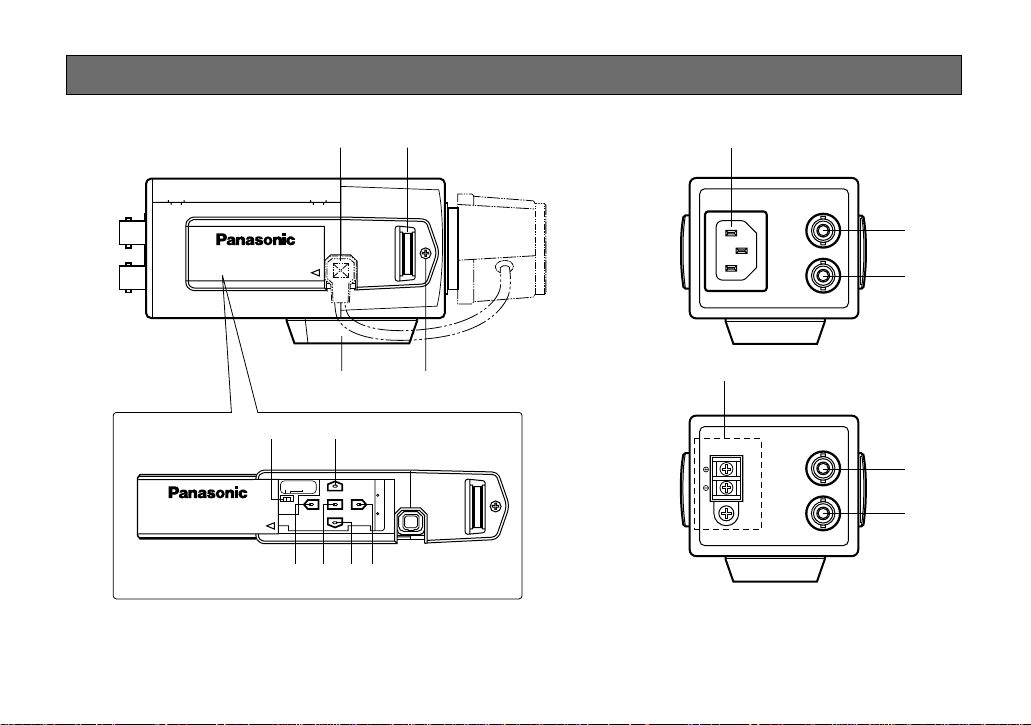
MAJOR OPERATING CONTROLS AND THEIR FUNCTIONS
Slide the panel to the left until it locks.
-6-

q Auto Iris Lens Connector
This connector is used to connect the auto iris lens
with a 4-pin male connector supplied as a standard
accessory (Part No. YFE4191J100).
u Left Button ( )
This button is used to move the cursor to the left. It
is also used to select the mode and can be used to
adjust some levels.
w Flange-back Adjusting Ring (FB)
This ring is used to adjust the back focal length or
picture focus. Rotate this ring upward or downward
for a CS-mount lens. In case of using a C-mount
lens, adjust it with the C-mount adapter.
e Focus Fixing Screw (LOCK)
r Camera Mounting Screw Hole
This hole is used to mount the camera onto a
mounting bracket.
t Down Button ( )
This button is used to move the cursor downward.
It is also used to select items in the CAM SET UP
menu.
y Right Button ( )
This button is used to move the cursor to the right.
It is also used to select the mode and can be used
to adjust some levels.
i Up Button ( )
This button is used to move the cursor upward. It is
also used to select items in the CAM SET UP menu.
o Set Button ( )
This button is used to activate an item selected in
the CAM SET UP menu.
!0 Gen-lock Termination Switch (Hi-Z, G/L 75Ω)
Set this switch to Hi-Z when a gen-lock video input
signal is looped through. In all other cases, set this
switch to 75 Ω.
!1 Gen-lock Input Connector (GEN-LOCK)
This connector is used to connect an external system for synchronization.
!2 Video Output Connector (VIDEO OUT)
This connector is used to connect with the VIDEO
IN connector of the monitor.
-7-

!3 Power Cord Socket
This socket is used to connect the power cord
(supplied as a standard accessory).
!4 AC/DC Compatible Input Terminal
(DC 12V IN/AC 24V IN)
This terminal is for connecting the 12 V DC or 24 V
AC power supply cord.
Cautions:
1. Connect to 12 V DC (10.5 V-16 V) or 24 V AC
(19.5 V-28 V) class 2 power supply only. Make
sure to connect the grounding lead to the GND
terminal when the power is supplied from a 24 V
AC power source.
2. To prevent fire or electric shock hazard, use a
UL listed cable (VW-1, style 1007) for the Input
Terminal.
-8-
CONNECTIONS
A. WV-CL920 (120 V AC 60Hz)
1. Plug the AC power cord (supplied as standard
accessory) into the AC Inlet Socket.
2. Connect the AC power cord to a 120 V AC 60 Hz
outlet.
Notes:
• Connect the power cord firmly.
• The power cord should be long enough for panning and tilting.
If the cable is too short, the power cord plug may
be pulled off the camera when the camera pans or
tilts.
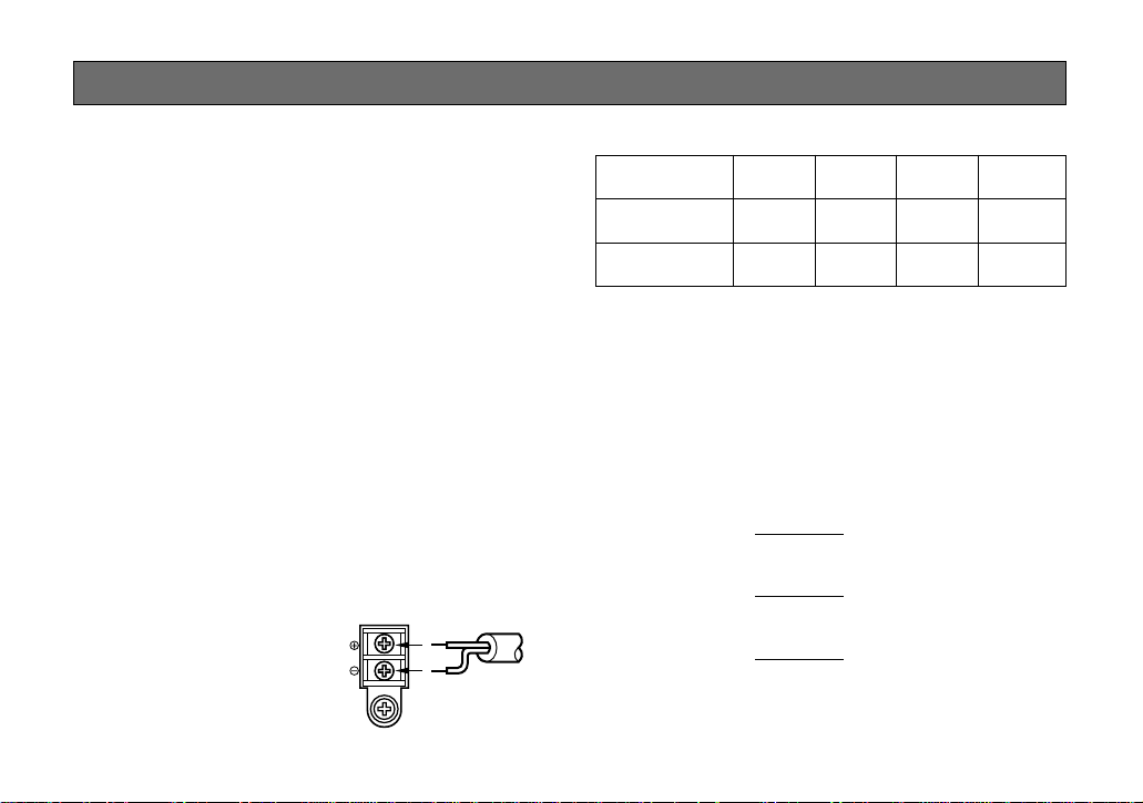
B. WV-CL924 (12 V DC/24 V AC)
The WV-CL924 has an AC/DC compatible input terminal. The 12 V DC or 24 V AC power supply cord can be
connected to this terminal. The camera detects the
power source automatically.
1. 12 V DC Power Supply
Connect the power cord to
the AC/DC compatible
input terminal on the rear
panel of the camera.
DC 12V
IN
AC 24V
IN
GND
1
2
12 V DC
(10.8 V - 16 V)
Resistance of copper wire [at 20°C (68°F)]
Copper wire #24 #22 #20 #18
size (AWG) (0.22 mm2) (0.33 mm2) (0.52 mm2) (0.83 mm2)
Resistance 0.078 0.050 0.030 0.018
Ω/m
Resistance 0.026 0.017 0.010 0.006
Ω/ft
• Calculation of maximum cable length between
camera and power supply.
10.8 V DC ≤ V
A − (R x 0.42 x L) ≤ 16 V DC
L : Cable length (m)
R : Resistance of copper wire (Ω/m)
V
A : DC output voltage of power supply unit
V
L standard = (m)
L minimum = (m)
L maximum = (m)
A − 12
0.42 x R
V
A − 16
0.42 x R
V
A − 10.5
0.42 x R
-9-
2. 24 V AC Power Supply
Connect the power cable to the AC/DC compatible
input terminal on the rear panel of the camera.
Video Cable
1. It is recommended to use a monitor whose resolution is at least equal to that of the camera.
AC 24V
DC 12V
IN
IN
1
2
GND
24 V AC, 60 Hz
(19.5 V - 28 V)
Recommended wire gauge sizes for 24 V AC line.
Copper wire #24 #22 #20 #18
size (AWG) (0.22 mm2) (0.33 mm2) (0.52 mm2) (0.83 mm2)
Length (m) 95 150 255 425
of Cable
(Approx.) (ft) 314 495 842 1 403
Caution:
To prevent fire or electric shock hazard,use a
UL listed cable (VW-1, style 1007).
2. The maximum extensible coaxial cable length
between the camera and the monitor is shown
below.
Type of RG-59/U RG-6/U RG-11/U RG-15/U
coaxial cable (3C-2V) (5C-2V) (7C-2V) (10C-2V)
Recommended (m) 250 500 600 800
maximum
cable length (ft) 825 1 650 1 980 2 640
-10-

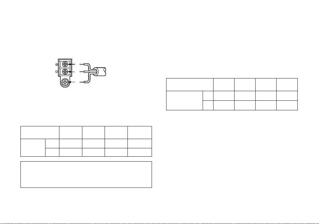
Installation of Auto Iris Lens Connector
Install the lens connector (YFE4191J100) when using a
video drive ALC lens.
The installation should be made by qualified service
personnel or system installers.
(1) Cut the iris control cable at the edge of the lens
connector to remove the existing lens connector
and then remove the outer cable cover as shown in
the diagram below.
The pin assignment of the lens connector is as follows:
Pin 1: Power source; +9 V DC, 50 mA Max.
Pin 2: Not used
Pin 3: Video signal; 1.3 V [p-p]/40 kΩ
Pin 4: Shield, ground
(2) Solder the lens cable to the pins of the supplied
connector.
Pin 3
Pin 1
Rib
Pin 4
Pin 2
-11-
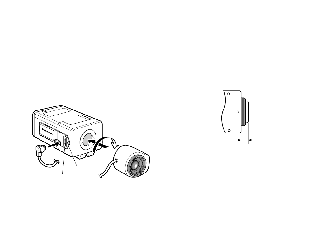
Screw
Flange-back
Adjusting Ring
w
q
Mounting the Lens
Caution:
Before you mount the lens, loosen the fixing screw
on the side of the camera, and rotate this ring
upward until it stops. If the ring is not at the end,
the inner glass or CCD image sensor may be damaged.
1. Mount the lens by turning it clockwise on the lens
mount of the camera.
2. Connect the lens cable to the auto iris lens connector on the side of the camera.
Caution for Mounting the Lens
The lens mount should be a CS-mount (1”-32UN). In
case of a C-mount, it should be a C-mount adapter and
the lens weight should be less than 450 g (0.99 lbs). If
the lens is heavier, both the lens and camera should be
secured by using the supporter.
The protrusion at the rear of the lens should be as
shown below:
CS-mount: Less than 4 mm (5/32”)
-12-
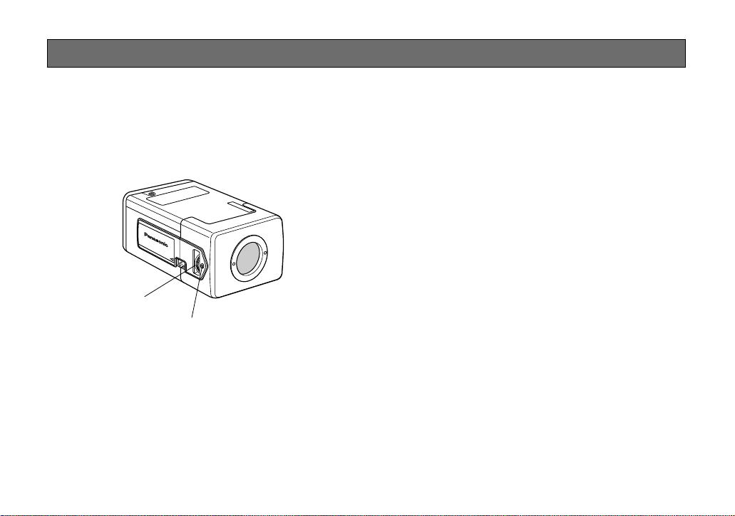
Screw
Flange-back
Adjusting Ring
FOCUS OR FLANGE-BACK ADJUSTMENT
The following adjustment should be made by qualified
service personnel or system installers.
1. Loosen the screw on the side of the camera.
2. Turn the flange-back adjusting ring to the desired
position.
Note: Adjusting a focus in the visible rays may be
soft-focused with the near-infrared light.
3. Tighten the screws on the side of the camera.
Caution: Tightening the screw by force will cause
damage to the screw or deviation of focus.
-13-
 Loading...