

Page 1

(Lens : option)
CL924
Before attempting to connect or operate this product,
please read these instructions carefully and save this manual for future use.
Model No. WV-CL920A
WV-CL924A
Color CCTV Cameras
Operating Instructions
W
V
-
CL924
Page 2
-2-
WARNING: To prevent fire or electric shock hazard, do not expose this appliance to rain or moisture. The apparatus shall not be exposed
to dripping or splashing and that no objects filled with liquids, such as vases, shall be placed on the apparatus.
The lightning flash with arrowhead
symbol, within an equilateral triangle, is
intended to alert the user to the presence of uninsulated "dangerous voltage" within the product's enclosure that
may be of sufficient magnitude to constitute a risk of electric shock to persons.
The exclamation point within an equilateral triangle is intended to alert the
user to the presence of important operating and maintenance (servicing)
instructions in the literature accompanying the appliance.
The serial number of this product may be found on the top
of the unit.
You should note the serial number of this unit in the space
provided and retain this book as a permanent record of your
purchase to aid identification in the event of theft.
Model No. WV-CL920A/CL924A
Serial No.
Warning:
This equipment generates and uses radio frequency energy
and if not installed and used properly, i.e., in strict accordance with the instruction manual, may cause harmful
interference to radio communications. It has been tested
and found to comply with the limits for a Class A computing
device pursuant to Subpart J of Part 15 of FCC Rules,
which are designed to provide reasonable protection
against such interference when operated in a commercial
environment.
CAUTION:
TO REDUCE THE RISK OF ELECTRIC SHOCK, DO
NOT REMOVE COVER (OR BACK). NO USER SERVICEABLE PARTS INSIDE.
REFER SERVICING TO QUALIFIED SERVICE PERSONNEL.
CAUTION
RISK OF ELECTRIC SHOCK
DO NOT OPEN
SA 1965
SA 1966
For U.S.A
Power disconnection. Unit with or without ON-OFF switches has power supplied to the unit whenever the power
cord is inserted into the power source;
however, the unit is operational only
when the ON-OFF switch is in the ON
position. Unplug the power cord to disconnect the main power for all unit.
Page 3

-3-
IMPORTANT SAFETY INSTRUCTIONS
1) Read these instructions.
2) Keep these instructions.
3) Heed all warnings.
4) Follow all instructions.
5) Do not use this apparatus near water.
6) Clean only with dry cloth.
7) Do not block any ventilation openings. Install in accordance with the manufacturer's instructions.
8) Do not use near any heat sources such as radiators, heat registers, stoves, or other apparatus (including amplifiers) that produce heat.
9) Do not defeat the safety purpose of the polarized or grounding-type plug. A polarized plug has two blades with
one wider than the other. A grounding-type plug has two blades and a third grounding prong. The wide blade or
the third prong are provided for your safety. If the provided plug does not fit into your outlet, consult an electrician for replacement of the obsolete outlet.
10) Protect the power cord from being walked on or pinched particularly at plugs, convenience receptacles and the
points where they exit from the apparatus.
11) Only use attachments/accessories specified by the manufacturer.
Page 4

-4-
12) Use only with the cart, stand, tripod, bracket, or table specified by the manufacturer, or sold with the apparatus.
When a cart is used, use caution when moving the cart/apparatus combination to avoid injury from tip-overs.
13) Unplug this apparatus during lightning storms or when unused for long periods of time.
14) Refer all servicing to qualified service personnel. Servicing is required when the apparatus has been damaged in
any way, such as power-supply cord or plug is damaged, liquid has been spilled or objects fallen into the apparatus, the apparatus has been exposed to rain or moisture, does not operate normally, or has been dropped.
S3125A
Page 5

-5-
CONTENTS
IMPORTANT SAFETY INSTRUCTIONS .......................................................................................................................... 3
PREFACE ....................................................................................................................................................................... 6
FEATURES ..................................................................................................................................................................... 7
PRECAUTIONS .............................................................................................................................................................. 8
MAJOR OPERATING CONTROLS AND THEIR FUNCTIONS ........................................................................................ 9
CONNECTIONS ............................................................................................................................................................. 12
FOCUS OR FLANGE-BACK ADJUSTMENT .................................................................................................................. 16
INSTALLATION OF CAMERA ........................................................................................................................................ 17
SETUP ............................................................................................................................................................................ 18
1. CAMERA SETUP MENU .......................................................................................................................................... 18
2. SETUP OPERATION ................................................................................................................................................ 21
SETTING PROCEDURES ............................................................................................................................................... 23
PREVENTION OF BLOOMING AND SMEAR ................................................................................................................. 42
SPECIFICATIONS .......................................................................................................................................................... 42
STANDARD ACCESSORIES .......................................................................................................................................... 44
OPTIONAL ACCESSORIES ............................................................................................................................................ 45
Page 6

-6-
PREF ACE
Panasonic's WV-CL920A (WV-CL924A) series digital
color camera introduces a new level of high picture
quality and high resolution through the use of a 1/2-inch
frame interline transfer CCD image sensor having 768
horizontal pixels (picture elements), and digital signal
processing LSI's. This model offers cutting-edge technology for advanced video surveillance.
Page 7

-7-
1. The following functions are built in.
(1) Auto Light Control (ALC)/Electronic Light
Control (ELC)
(2) Back Light Compensation (Auto: Factory pre-
set, Manual: Manual photometric measuring
area set)
(3) Various External Sync Functions, including
Gen-Lock
(4) Auto/Manual White Balance Function
(5) Electronic Shutter Function
2. Signal-to-noise ratio of 50 dB
3. Minimum illumination of 0.14 lx (0.014 footcandle)
with F1.4 lenses (Color mode)
4. Minimum illumination of 0.01 lx (0.001 footcandle)
with F1.4 lenses (Black and White mode)
5. 570 lines of horizontal resolution (Black and White
mode)
480 lines of horizontal resolution (Color mode)
FEATURES
6. High quality picture:
(a) 2H type vertical enhancer for greater picture
sharpness
(b) Chroma averaging circuit for better color signal
to noise ratio
(c) Minimum of aliasing on fine objects
(d) Expanded dynamic range by use of knee cir-
cuit
(e) Highlight aperture correction for greater picture
detail of bright objects
7. Ability to shoot indoor scenes with fixed iris lens by
use of Electronic Light Control (ELC) function.
8. Selectable electronic sensitivity enhancing modes
including: AUTO, MANUAL and OFF
9. Built in Digital Motion Detector
10. Auto Black/White mode enables the camera to
switch between C/L and B/W in response to input
lights.
Page 8

-8-
1. The installation should be made by qualified
service personnel or system installers.
2. Do not attempt to disassemble the camera.
To prevent electric shock, do not remove screws or
covers.
There are no user serviceable parts inside. Ask a
qualified service person for servicing.
3. Handle the camera with care.
Do not abuse the camera. Avoid striking, shaking,
etc. The camera could be damaged by improper
handling or storage.
4. Do not use strong or abrasive detergents when
cleaning the camera body.
Use a dry cloth to clean the camera when dirty.
In case the dirt is hard to remove, use a mild detergent and wipe gently. Afterwards, wipe off the
remained part of the detergent in it with a dry cloth.
5. Clean the CCD faceplate with care.
Do not clean the CCD with strong or abrasive detergents. Use lens tissue or a cotton tipped applicator
and ethanol.
6. Never face the camera towards the sun.
Do not aim the camera at bright objects. Whether
the camera is in use or not, never aim it at the sun
or other extremely bright objects. Otherwise,
blooming or smear may be caused.
7. Do not operate the camera beyond the specified
temperature, humidity or power source ratings.
Use the camera under conditions where temperature is between –10 °C - +50 °C (14 °F - 122°F), and
humidity is below 90 %. The input power source is
120 V AC 60 Hz for WV-CL920A and 12 V DC/24 V
AC for WV-CL924A.
PRECAUTIONS
Caution:
To prevent fire or electric shock hazard, use a
UL listed cable (VW-1, style 1007) for the DC
12 V or AC 24 V Input Terminal.
Page 9
-9-
<WV-CL920A>
<WV-CL924A>
WV-
CL920A
FB LOCK
FB LOCK
Hi-Z G/L 75
Ω
WV-
CL920A
VIDEO OUT
GEN-LOCK
AC 24V
IN
DC 12V
IN
GND
2
1
r
e
!3
!3
!2
!2
!1
q w
!0i
ytu
o
!6
!4
!5
!7
VIDEO OUT
GEN-LOCK
GND
120V AC 60Hz
OUT
ALARM
DAY/
NIGHT
GND
IN
GND
OUT
ALARM
DAY/
NIGHT
GND
IN
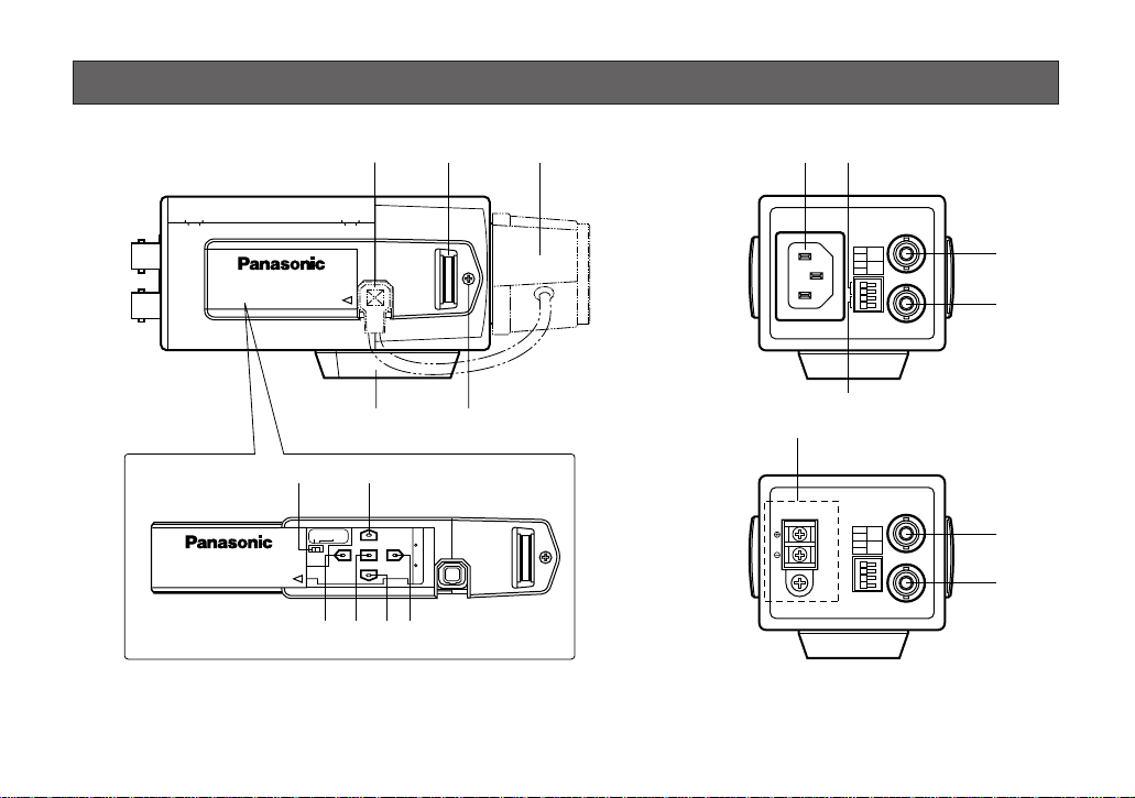
MAJOR OPERATING CONTROLS AND THEIR FUNCTIONS
Slide the panel to the left until it locks.
Page 10

-10-
q Auto Iris Lens Connector
This connector is used to connect the auto iris lens
with a 4-pin male connector supplied as a standard
accessory (Part No. YFE4191J100).
w Flange-back Adjusting Ring (FB)
This ring is used to adjust the back focal length or
picture focus. Rotate this ring upward or downward
for a CS-mount lens. In case of using a C-mount
lens, adjust it with the C-mount adapter.
e Lens (Option)
r Focus Fixing Screw (LOCK)
t Camera Mounting Screw Hole
This hole is used to mount the camera onto a
mounting bracket.
y Down Button (K)
This button is used to move the cursor downward. It
is also used to select items in the CAM SET UP
menu.
u Right Button (M)
This button is used to move the cursor to the right.
It is also used to select the mode and can be used
to adjust some levels.
i Left Button (L)
This button is used to move the cursor to the left. It
is also used to select the mode and can be used to
adjust some levels.
o Up Button (J)
This button is used to move the cursor upward. It is
also used to select items in the CAM SET UP menu.
!0 Set Button (I)
This button is used to activate an item selected in
the CAM SET UP menu.
!1 Gen-lock Termination Switch (Hi-Z, G/L 75Ω)
Set this switch to Hi-Z when a gen-lock video input
signal is looped through. In all other cases, set this
switch to 75 Ω.
!2 Gen-lock Input Connector (GEN-LOCK)
This connector is used to connect an external system for synchronization.
!3 Video Output Connector (VIDEO OUT)
This connector is used to connect with the VIDEO
IN connector of the monitor.
Page 11

-11-
!4 Alarm Output Terminal (ALARM OUT/GND)
Connects to the alarm input connector (terminal) of
an external device. When the camera detects
motion, the alarm output signal is supplied to the
connected external device (Open collector output:
16 V DC, 100 mA max).
!5 Day/Night Input Terminal (DAY/NIGHT IN/GND)
This terminal is used for connecting the camera to
an external day/night detecting sensor.
!6 AC Inlet Socket
Plug the power cord (supplied as a standard
accessory) into this socket and connect it to an AC
outlet.
!7 AC/DC Compatible Input Terminal
(DC 12V IN/AC 24V IN, GND)
This terminal is for connecting the 12 V DC or 24 V
AC power supply cord.
Caution: Connect to 12 V DC (10.8 V-16 V) or 24 V
AC (19.5 V-28 V) class 2 power supply only. Be
sure to connect the grounding lead to the GND
terminal when the power is supplied from a 24 V
AC power source.
Page 12

-12-
Copper wire #24 #22 #20 #18
size (AWG) (0.22 mm2) (0.33 mm2) (0.52 mm2) (0.83 mm2)
Resistance 0.078 0.050 0.030 0.018
Ω/m
Resistance 0.026 0.017 0.010 0.006
Ω/ft
A. WV-CL920A (120 V AC 60Hz)
1. Plug the AC power cord (supplied as standard
accessory) into the AC Inlet Socket.
2. Connect the AC power cord to a 120 V AC 60 Hz
outlet.
Notes:
• Connect the power cord firmly.
• The power cord should be long enough for panning
and tilting.
If the cable is too short, the power cord plug may
be pulled off the camera when the camera pans or
tilts.
B. WV-CL924A (12 V DC/24 V AC)
Cautions:
1. Connect to 12 V DC (10.8 V - 16 V) or 24 V AC
(19.5 V - 28 V) class 2 power supply only. Be sure
to connect the grounding lead to the GND terminal
when the power is supplied from a 24 V AC power
source.
2. To prevent fire or electric shock hazard, use a UL
listed cable (VW-1, style 1007) for the Input
Terminal.
3. The connections should comply with National
Electrical Code (NEC).
The WV-CL924A has an AC/DC compatible input terminal. The 12 V DC or 24 V AC power supply cord can be
connected to this terminal. The camera detects the
power source automatically.
1. 12 V DC Power Supply
Connect the power cord
to the AC/DC compatible
input terminal on the rear
panel of the camera.
Resistance of copper wire [at 20°C (68°F)]
12 V DC
(10.8 V - 16 V)
You can use the formula below to select the power supply, and power cable. The voltage supplied to the
power-in terminals must be between 10.8 V - 16 V.
10.8V(minimum) ≤ V
A – 2RLI ≤ 16V (maximum)
V
A
: Output voltage of power supply
R: Resistance (Ω/m) (Ω/ft), see table
L: Cable length (m) (ft)
I: Current consumption (A), see specifications
CONNECTIONS
AC 24V
DC 12V
IN
IN
1
2
GND
Page 13

-13-
2. 24 V AC Power Supply
Connect the power cable to the AC/DC compatible
input terminal on the rear panel of the camera.
Recommended wire gauge sizes for 24 V AC line.
Video Cable
1. It is recommended to use a monitor whose resolution is at least equal to that of the camera.
2. The maximum extensible coaxial cable length
between the camera and the monitor is shown
below.
Copper wire #24 #22 #20 #18
size (AWG) (0.22 mm2) (0.33 mm2) (0.52 mm2) (0.83 mm2)
Length (m) 95 150 255 425
of Cable
(Approx.) (ft) 314 495 842 1 403
24 V AC, 60 Hz
(19.5 V - 28 V)
Alarm and DAY/NIGHT Connections
1. Connect an optical sensor to the DAY/NIGHT IN terminal.
• Color/black-and-white input terminal with a capacity
of 5 V DC pull-up input, 0.2 mA or more.
OFF: Open contact (Color)
ON: Closed contact (Black-and-white)
Note: To activate the Day/Night function, set BW
mode to EXT on the special menu.
2. Connect an external device such as a buzzer or
lamp to the ALARM terminal.
• The alarm output terminal is an open collector terminal with a capacity of 16 V DC, 100 mA maximum.
OFF: Open contact (Inactive)
ON: Closed contact 100 mA maximum (Active)
Note: Use a relay if the voltage or current of the
connected device exceeds the ratings.
Type of RG-59/U RG-6/U RG-11/U RG-15/U
coaxial cable (3C-2V) (5C-2V) (7C-2V) (10C-2V)
Recommended (m) 250 500 600 800
maximum
cable length (ft) 825 1 650 1 980 2 640
AC 24V
DC 12V
IN
IN
1
2
GND
Page 14

-14-
Replacement of Auto Iris Lens
Connector
If necessary, replace the existing lens connector with
the type YFE419J100 supplied.
1. Cut the existing lens connector at the end of the iris
control cable.
2. Process the cable end as shown in the figure.
Cover
Lens
3. Solder each wire to a pin as follows.
Pin #1: Red/Power
Pin #2: Not used
Pin #3: White/Video
Pin #4: Black/GND, Shield
4. Attach the cover to the connector.
Pin 3
Pin 1
Rib
Pin 4
Pin 2
8 mm (5/8)
2 mm (1/16)
Page 15

-15-
Caution for Mounting the Lens
The lens mount should be a CS-mount (1”-32UN). In
case of a C-mount, it should be a C-mount adapter and
the lens weight should be less than 450 g (0.99 lbs). If
the lens is heavier, both the lens and camera should be
secured by using the supporter.
The protrusion at the rear of the lens should be as
shown below:
CS-mount: Less than 4 mm (5/32”)
Screw
Flange-back
Adjusting Ring
w
q
Mounting the Lens
Caution:
Before you mount the lens, loosen the fixing screw
on the side of the camera, and rotate the flangeback adjusting ring counterclockwise until it stops.
If the ring is not at the end, the inner glass or CCD
image sensor may be damaged.
1. Mount the lens by turning it clockwise on the lens
mount of the camera.
2. Connect the lens cable to the auto iris lens connector on the side of the camera.
Page 16

The following adjustment should be made by qualified
service personnel or system installers.
1. Loosen the screw on the side of the camera.
2. Turn the flange-back adjusting ring to the desired
position.
Note: Adjusting a focus in the visible rays may be
soft-focused with the near-infrared light.
-16-
3. Tighten the screws on the side of the camera.
Caution: Tightening the screw by force will cause
damage to the screw or deviation of focus.
FOCUS OR FLANGE-BACK ADJUSTMENT
Flange-back
Adjusting Ring
Screw
Page 17

-17-
Fixing Screws
Mount Adapter
• Mounting from the top
Remove the mount adapter from the bottom of the
camera by removing the two fixing screws. Attach
the mount adapter to the top as shown in the diagram, then mount the camera on the mounting
bracket.
Use the two original screws to attach the mount
adapter to the camera. Using shorter ones may
cause the camera to fall down, and using longer
ones may damage the inside of the camera.
INSTALLA TION OF CAMERA
Page 18

-19-
White
Balance
ATW1 ATW2 AWC
Motion
Detector
Special
Menu
Display
Mode
CHROMA
GAIN
UP SIDE
DOWN
AP
GAIN
PEDESTAL
BW
BURST
(BW)
ON OFF
Camera
Resetting
Manual
Mask Area
Selection
Detection
Level
Adjustment
Lens Drive Signal
Selection
AUTO1 AUTO2 EXT OFF ON
Manual
Mask Area
Selection
DWELL
TIME
Selection
HUE
DC
VIDEO
-18-
1. CAMERA SETUP MENU
This camera utilizes a user setup menu that is displayed on-screen.
The setup menu contains various items that form a tree type structure.
SETUP
Camera
ID
ON/OFF
Light
Control
ALC ELC
Shutter
Speed
CAM SETUP
AGC
ON(DNR-H)/ON(DNR-M)/
ON(DNR-L)/OFF
SYNC
INT/LL
Camera
ID
Editing
Camera ID
Display
Position
PRESET
OFF
PRESET
OFF
PRESET ON
(Back Light
Compensation)
PRESET ON
(Back Light
Compensation)
VBS
Automatic
Selection
VS
Automatic
Selection
LL
Manual
Selection
Manual
Mask Area
Selection
Manual
Level
Selection
Peak
Mode
Selection
Peak
Mode
Selection
H.Phase
SC.Phase
Manual
Adjustment
H.Phase
Manual
Adjustment
V.Phase
Manual
Adjustment
AGC MAX
Level
Adjustment
Electronic
Sensitivity
Enhancement
OFF/AUTO/FIX
Manual
Mask Area
Selection
Manual
Level
Selection
Peak
Mode
Selection
Peak
Mode
Selection
Page 19

• Opening the Setup Menu
Hold down I for 2 seconds or more to display the
CAM SET UP menu. You can confirm the current settings on the menu.
Check the current settings on the menu.
Move the cursor to END in the bottom line, and press
I to close the menu and return to the camera picture.
-20-
Blinking
Note: The menu displayed on the monitor will close and
change to the camera picture if no button is
pressed for 5 minutes.
** CAM SET UP **
CAMERA ID OFF
ALC/ELC ALC
SHUTTER OFF
AGC ON(DNR-H)
SENS UP OFF
SYNC INT
WHITE BAL ATW1
MOTION DET OFF
LENS DRIVE DC
END SET UP DISABLE
↵↵
↵
↵
Page 20

2. SETUP OPERATION
This camera utilizes a user setup menu (CAM SET UP)
that is displayed on the monitor.
To set items on the CAM SET UP menu, use the following buttons on the side panel.
Up Button (J): Moves the cursor upwards. Use
this button to select an item or
adjust the parameters.
Down Button (K): Moves the cursor downwards. Use
this button to select an item or
adjust the parameters.
Right Button (M): Moves the cursor to the right. Use
this button to select or adjust the
parameters of the selected item.
The parameter changes each time
this button is pressed.
-21-
Left Button
Set Button
Right Button
Down Button
Up Button
Left Button (L): Moves the cursor to the left. Use
this button to select or adjust the
parameters of the selected item.
The parameter changes each time
this button is pressed.
Set Button (I): Executes selection and displays a
submenu for an item with N mark.
• To reset the parameter of an item to the factory
default setting, move the cursor to that row and
press L and M simultaneously.
• To return to the previous menu or page, move the
cursor to RET and press I.
• To close the setup menu, move the cursor to END
and press I.
• All Reset Operation
All reset allows you to reset all adjustments and parameters to the factory default settings.
(1) Make sure that the setup menu is not displayed (a
camera picture is displayed).
(2) While pressing both L and M, press I for a
few seconds. The message ALL RESET momentarily appears on the monitor.
Page 21

-22-
• Editing the CAM SET UP Menu
To edit the CAM SET UP menu (change settings), press
J and K or L and M to move the cursor to SET
UP DISABLE in the bottom line.
Press I. SET UP DISABLE changes to SET UP
ENABLE. Move the cursor to END, then to the item(s)
you want to change.
Notes:
• When SET UP DISABLE appears in the bottom line
of the CAM SET UP menu, you cannot change the
currently active settings. This is to prevent accidental changing of the settings.
• When the setup menu is closed after changing the
parameters in the menu, the new values are saved
in the EEPROM (Electric Erasable and
Programmable Read Only Memory). These values
remain valid until new values are saved, even if the
power of the camera is off.
** CAM SET UP **
CAMERA ID OFF
ALC/ELC ALC
SHUTTER OFF
AGC ON(DNR-H)
SENS UP OFF
SYNC INT
WHITE BAL ATW1
MOTION DET OFF
LENS DRIVE DC
END SET UP DISABLE
↵↵
↵
↵
↵
** CAM SET UP **
CAMERA ID OFF
ALC/ELC ALC
SHUTTER OFF
AGC ON(DNR-H)
SENS UP OFF
SYNC INT
WHITE BAL ATW1
MOTION DET OFF
LENS DRIVE DC
END SET UP ENABLE
↵↵
↵
Page 22

-23-
1. Camera Identification (CAMERA ID)
Setting
You can use the camera identification (CAMERA ID)
menu to assign a name to the camera. The camera ID
consists of up to 16 alphanumeric characters. The camera ID display can be switched on or off on the monitor
screen.
Camera ID ON/OFF
Move the cursor to CAMERA ID, and select ON or OFF.
ON: Displays the camera ID in the specified position on
the monitor.
OFF: Does not display.
To edit the CAMERA ID
1. Press I. The CAMERA ID menu appears. The
cursor on the letter “0” is highlighted.
2. Move the cursor to the character you want to edit
by pressing L/M/J/K.
3. After selecting the character, press I. The
selected character appears in the editing area.
(The pointer in the editing area moves to the right
automatically at this moment.)
4. Repeat the steps above until all characters are edited.
To enter a blank space in the CAMERA ID
Move the cursor to SPACE and press I.
To replace a specific character in the CAMERA ID
1. Move the cursor to the editing area by pressing
K.
SETTING PROCEDURES
Character Cursor
Pointer
Character
Area
Command
Editing
Area
CAMERA ID menu
0123456789
ABCDEFGHIJKLM
NOPQRSTUVWXYZ
().,'":;&#!?=
+-*/%$
SPACE
POSI RET END RESET
................
** CAM SET UP **
CAMERA ID OFF
ALC/ELC ALC
SHUTTER OFF
AGC ON(DNR-H)
SENS UP OFF
SYNC INT
WHITE BAL ATW1
MOTION DET OFF
LENS DRIVE DC
END SET UP ENABLE
↵↵
↵
↵
Page 23

-24-
2. Move the pointer to the character to be replaced by
pressing L or M. Then move the cursor to the
character area and select a new character.
3. Press I to determine the CAMERA ID.
To erase all characters in the editing area
Move the cursor to RESET and press I. All characters in the editing area disappear.
To determine the display position of the CAMERA ID
1. Move the cursor to POSI, and press I. The dis-
play shown below appears and the CAMERA ID is
highlighted.
2. Move the CAMERA ID to the desired position by
pressing L/M/J/K.
3. Press I to fix the position of the CAMERA ID.
The mode returns to the previous CAMERA ID
menu.
Notes:
• The CAMERA ID stops at the edges of the monitor screen.
• The CAMERA ID moves faster if any of L/
M/J/K is kept pressed for a second or
more.
2. Light Control Setting (ALC/ELC)
You can select the mode for adjusting the lens iris.
The modes are as follows:
ALC: Select this mode when an auto iris lens (ALC
lens) is used with this camera.
ELC: Select this mode when a fixed iris lens or manual
iris lens is used with this camera.
** CAM SET UP **
CAMERA ID OFF
ALC/ELC ALC
SHUTTER OFF
AGC ON(DNR-H)
SENS UP OFF
SYNC INT
WHITE BAL ATW1
MOTION DET OFF
LENS DRIVE DC
END SET UP ENABLE
↵↵
↵
↵
Highlighted
WV-CL920A
Page 24

-25-
1. Move the cursor to the ALC/ELC parameter.
2. Select ALC or ELC.
Cautions:
1. Under bright lighting conditions such as outdoors,
use an ALC type lens because the ELC control
range is not wide enough under these conditions.
2. Use an ALC type lens if the following phenomena
occur:
• Strong smear and/or blooming on highlight
objects such as spotlight or sunlight from windows.
• Noticeable flicker in the picture and/or color
rendition variations.
3. If ELC is selected, SHUTTER is not available.
Back Light Compensation (BACK LIGHT COMP)
Back light compensation is available for both the ALC
and ELC modes. It eliminates strong background lighting which makes the camera picture dark, such as a
spotlight. You can select one of two modes (PRESET
ON or PRESET OFF) of back light compensation.
2-1. ALC Mode with PRESET ON
In normal use, the important object in a scene is placed
in the center of the monitor’s screen. In the factory
setup mode, more photometric weight is given to the
center of the screen (where the important object is
located) than to the edge of the picture (where a bright
backlight would most likely be located). In this mode,
the object at the center of the screen will always be
clearly visible regardless of backlight variations.
Note: If ELC is selected, set LEVEL according to this
procedure.
1. Select ALC and press I. The ALC CONT menu
appears.
** CAM SET UP **
CAMERA ID OFF
ALC/ELC ALC
SHUTTER OFF
AGC ON(DNR-H)
SENS UP OFF
SYNC INT
WHITE BAL ATW1
MOTION DET OFF
LENS DRIVE DC
END SET UP ENABLE
↵↵
↵
↵
Page 25

-26-
** ALC CONT **
BACK LIGHT COMP
PRESET OFF
PEAK MODE OFF
MASK SET
LEVEL ...I.....
- +
RET END
↵
** ALC CONT **
BACK LIGHT COMP
PRESET ON
PEAK MODE OFF
LEVEL ...I.....
- +
RET END
2. Move the cursor to the PRESET parameter and
select ON.
The backlight compensation is automatically set.
3. If you want to change the video output level (picture
contrast), move the “I” cursor for LEVEL and adjust
the level.
4. Move the cursor to RET and press I to return to
the CAM SET UP menu.
2-2. ALC Mode with PRESET OFF
These modes are effective when the main object in the
scene is not located in the center of the screen and a
source of bright light is located near the center of the
screen. In these modes, the picture is divided into 48
areas that mask the light to keep the clarity of the picture.
Note: If ELC is selected, set MASK SET and LEVEL
according to this procedure.
1. Move the cursor to the PRESET parameter and
select OFF.
The item MASK SET appears on the menu.
** ALC CONT **
BACK LIGHT COMP
PRESET OFF
PEAK MODE OFF
MASK SET
LEVEL ...I.....
- +
RET END
↵
Page 26

-27-
2. Move the cursor to MASK SET and press I.
The 48 mask areas appear on the monitor screen.
The cursor is blinking in the top left corner of the
screen.
3. Move the cursor to the area where backlight is
bright, and press I to mask that area. The mask
turns white. (When the cursor is moved on an area
that has already been masked, the mask and cursor start blinking.)
4. Repeat step 3 to mask the desired area. To cancel
masking, move the cursor to that area and press
I.
5. After masking is completed, press I for 2 seconds or more. The ALC CONT menu appears.
6. If you want to change the video output level (picture
contrast), move the “I” cursor LEVEL and adjust the
level.
7. Move the cursor to RET and press I to return to
the CAM SET UP menu. (To return to the camera
picture, move the cursor to END and press I).
Caution: When an auto iris lens requiring a DC
control signal is used, the lens iris is fully
opened in ELC mode.
Blinking
Turns to white
Blinking
Blinking
Page 27

The preset values for SHUTTER (electronic shutter
speed) change by pressing L or M as follows:
4. Gain Control Setting (AGC ON/OFF)
You can select an automatic gain control (AGC) mode
with dynamic noise reduction (DNR) options.
1. Move the cursor to AGC and select a mode.
OFF: Applies neither AGC nor DNR.
ON (DNR-H): Applies AGC with high-level DNR.
ON (DNR-M): Applies AGC with middle-level DNR.
ON (DNR-L): Applies AGC with low-level DNR.
-28-
2-3.
Compensating Flare Phenomenon (PEAK MODE)
There may be cases where the lens causes the displayed picture to sway like a flare especially when a
strong light is input. You can compensate for this undesired effect.
Move the cursor to PEAK MODE, and select ON or OFF.
ON: Compensates flaring of the picture.
OFF: Does not compensate.
3. Shutter Speed Setting (SHUTTER)
Note: When ELC is selected for ALC/ELC on the CAM
SET UP menu, this item is not available.
You can select an electronic shutter speed of 1/60
(OFF), 1/100, 1/250, 1/500, 1/1 000, 1/2 000, 1/4 000, or
1/10 000 seconds.
Move the cursor to the SHUTTER parameter and select
the electronic shutter speed.
** CAM SET UP **
CAMERA ID OFF
ALC/ELC ALC
SHUTTER OFF
AGC ON(DNR-H)
SENS UP OFF
SYNC INT
WHITE BAL ATW1
MOTION DET OFF
LENS DRIVE DC
END SET UP ENABLE
↵
↵
↵
↵
OFF (1/60) 1/100
1/250 1/500
1/10 000 1/4 000 1/2 000 1/1 000
** CAM SET UP **
CAMERA ID OFF
ALC/ELC ALC
SHUTTER OFF
AGC ON(DNR-H)
SENS UP OFF
SYNC INT
WHITE BAL ATW1
MOTION DET OFF
LENS DRIVE DC
END SET UP ENABLE
↵↵
↵
↵
Page 28

5. Electronic Sensitivity Enhancement
(SENS UP)
There are two modes for SENS UP.
AUTO: If you select x32 AUTO, for example, the
sensitivity is raised automatically to x32 max.
When AUTO is selected, AGC is automatically
set to ON.
FIX: If you select x64 FIX, for example, the sensitivi-
ty is raised to just x64.
Move the cursor to the SENS UP parameter and select
the parameter for electronic sensitivity enhancement.
The preset values for SENS UP (electronic sensitivity
enhancement) change by pressing L or M as follows:
-29-
Notes:
• The higher the DNR level becomes, the more after
images and the less noise you will see.
• Selecting DNR-L is recommended when the picture
contains moving objects.
• When using a system controller, the parameters
(DNR-H/M/L) will not appear on its setup menu.
2. Press I (set) to open the AGC MAX (maximum
level) menu.
3. Move the "I" cursor with L or M to adjust the
AGC level.
4. Move the cursor to RET and press I to return to
the CAMERA SETUP menu. When closing the
menu, move the cursor to END and press I.
** AGC MAX **
LEVEL ....I....
- +
RET END
** CAM SET UP **
CAMERA ID OFF
ALC/ELC ALC
SHUTTER OFF
AGC ON(DNR-H)
SENS UP OFF
SYNC INT
WHITE BAL ATW1
MOTION DET OFF
LENS DRIVE DC
END SET UP ENABLE
↵↵
↵
↵
OFF
X2 AUTO
X4 AUTO X6 AUTO X10 AUTO
X32 FIXX64 FIX X16 FIX X10 FIX X6 FIX X4 FIX X2 FIX OFF
X16 AUTO
X32 AUTO
Page 29

-30-
• Whenever the multiplexed vertical drive pulse (VD2)
is supplied to the camera from an external equipment such as a Matrix Switcher, the camera sync
mode is automatically switched to the VD2 mode.
• When the VBS or VS gen-lock mode is to be used
select INT from this menu and supply the gen-lock
input signal to the Gen-lock Input Connector on the
rear panel.
• The VBS gen-lock mode has a submenu for horizontal and subcarrier phase adjustments. When the
cable length of the video output or the gen-lock
input is changed, the horizontal and subcarrier
phase must be re-adjusted.
• The VS gen-lock mode has a submenu for horizontal phase adjustments. When the cable length of
the video output or the gen-lock input is changed,
the horizontal phase must be re-adjusted.
• The line-lock mode has a submenu for line-lock vertical phase adjustment. If the camera installation is
relocated, check the vertical phase adjustment
again since the AC line phase may be different.
Notes:
• While the SENS UP function is active, the increased
sensitivity may cause noise, spots or a whitish phenomenon to appear in the picture. This is a normal
phenomenon.
• x64 FIX does not appear for the SENS UP parameter on the system controller setup menu.
• In case of using the WV-CU204 or WV-CU254
Controller, status does not appear correctly for the
SENS UP parameter on the setup menu.
6. Synchronization Setting (SYNC)
Rules on synchronization
• The priorities for the sync mode are as follows. A
higher mode will overrule lower ones.
1. Multiplexed Vertical Drive (VD2) (Highest priority)
2. Line-lock (LL)
3. Color Composite Video or Blackburst Signal
(VBS)
4. B/W Composite Video or Composite Sync
Signal (VS)
5. Internal Sync (INT) (Lowest priority)
• When the internal sync mode is to be used, select
INT. No gen-lock input signal should be supplied to
the Gen-lock Input Connector on the rear panel.
Page 30

-31-
6-1. Internal Sync Mode (INT)
1. Move the cursor to SYNC and select INT.
2. Press I.
Note: Never supply VD2, VBS, or VS to the camera
when you intend to operate the camera in the
internal mode. Otherwise your selection will be
ignored because INT has the lowest priority.
6-2. VBS Gen-lock Mode (EXT(VBS))
1. Move the cursor to the SYNC parameter and select
INT.
2. Connect the coaxial cable for the blackburst or
composite color video signal to the gen-lock input
connector.
3. Confirm that the INT parameter changed to EXT
(VBS) on the menu.
Caution: The gen-lock input signal should meet the
EIA specifications and should not contain jitter,
such as a VCR playback signal, as it could disturb synchronization.
4. After confirming that the cursor is on EXT (VBS),
press I. The phase adjustment menu appears
on the monitor.
5. Supply the video output signal of the camera to be
adjusted and the reference gen-lock input signal to
a dual-trace oscilloscope.
** CAM SET UP **
CAMERA ID OFF
ALC/ELC ALC
SHUTTER OFF
AGC ON(DNR-H)
SENS UP OFF
SYNC INT
WHITE BAL ATW1
MOTION DET OFF
LENS DRIVE DC
END SET UP ENABLE
↵↵
↵
↵
** CAM SET UP **
CAMERA ID OFF
ALC/ELC ALC
SHUTTER OFF
AGC ON(DNR-H)
SENS UP OFF
SYNC INT
WHITE BAL ATW1
MOTION DET OFF
LENS DRIVE DC
END SET UP ENABLE
↵↵
↵
** CAM SET UP **
CAMERA ID OFF
ALC/ELC ALC
SHUTTER OFF
↵
AGC ON(DNR-H)
SENS UP OFF
SYNC EXT(VBS)
WHITE BAL ATW1
MOTION DET OFF
LENS DRIVE DC
END SET UP ENABLE
** SYNC **
H PHASE ........I
- +
SC COARSE 1(1--4)
SC FINE ....I....
↵↵
↵
↵
↵
- +
RET END
Page 31

-32-
6. Set the oscilloscope to the horizontal rate and
expand the horizontal sync portion on the oscilloscope.
7. Move the cursor to H PHASE.
8. Adjust the horizontal phase by pressing L or M.
The adjustable range is 0 - 2.0 µs.
9. Move the cursor to SC COARSE.
10. Press L or M to match the chroma phase of the
camera’s video signal, when observed at the output
of the Special Effect Generator (SEG) or Switcher,
as closely as possible to the color of the original
scene. (SC COARSE adjustment can be incremented in steps of 90 degrees (4 steps) by pressing L
or M.)
Note: After the fourth step, the adjustment returns
to the first step.
1 (1 - - 4): 0 degrees
2 (1 - - 4): 90 degrees
3 (1 - - 4): 180 degrees
4 (1 - - 4): 270 degrees
11. Move the cursor to SC FINE.
12. Press L or M to match the color (hue) of the
camera’s video signal, when observed at the output
of the Special Effect Generator (SEG) or Switcher,
as closely as possible to the color of the original
scene.
The SC FINE adjustment has a range of 90 degrees
of color shift.
Notes:
• When the “I” cursor reaches the “+” end, it
jumps back to “–”. At the same time, SC
COARSE is incremented by one step to enable
a continuous adjustment. The reverse takes
place when the “I” cursor reaches the “–” end.
• When L or M is kept pressed for a second
or more, the “I” cursor moves faster.
• For more accurate adjustment, supply both the
original camera video output signal and the
effect output video signal (program output
video signal) of the special effects generator
(SEG) to a vectorscope and compare the chroma phase of both signals.
• To reset SC COARSE and SC FINE to the values preset at the factory, press L and M
simultaneously.
Page 32

-33-
6-3. VS Gen-lock Mode (EXT(VS))
1. Move the cursor to the SYNC parameter and select
INT.
2. Connect the coaxial cable for the composite sync
or composite B/W video signal to the gen-lock input
connector.
3. Confirm that the parameter INT changed to EXT
(VS) on the menu.
Caution: The gen-lock input signal should meet the
EIA specifications and should not contain jitter,
such as a VCR playback signal, as it could disturb synchronization.
4. After confirming that the cursor is on EXT (VS),
press I. The phase adjustment menu appears
on the monitor.
5. Supply the video output signal of the camera to be
adjusted and the reference gen-lock input signal to
a dual-trace oscilloscope.
6. Set the oscilloscope to the horizontal rate and
expand the horizontal sync portion on the oscilloscope.
7. Move the cursor to H PHASE.
8. Adjust the horizontal phase by pressing L or M.
The adjustable range is 0 - 2.0 µs.
6-4. Line-lock Sync Mode (LL)
Note: The line-lock mode is not applicable when
DC power and/or VD2 synchronization is supplied to the camera.
1. Move the cursor to the SYNC parameter and select
LL.
** CAM SET UP **
CAMERA ID OFF
ALC/ELC ALC
SHUTTER OFF
AGC ON(DNR-H)
SENS UP OFF
SYNC INT
WHITE BAL ATW1
MOTION DET OFF
LENS DRIVE DC
END SET UP ENABLE
↵↵
↵
** CAM SET UP **
CAMERA ID OFF
ALC/ELC ALC
SHUTTER OFF
AGC ON(DNR-H)
↵
SENS UP OFF
SYNC EXT(VS)
WHITE BAL ATW1
MOTION DET OFF
LENS DRIVE DC
END SET UP ENABLE
↵↵
** SYNC **
H PHASE ........I
- +
RET END
↵
↵
↵
Page 33

-34-
2. After confirming the cursor is on LL, press I. The
vertical phase adjustment menu appears on the
monitor.
3. Supply the video output signal of the camera to be
adjusted and the reference camera video output
signal to a dual-trace oscilloscope.
4. Set the oscilloscope to the vertical rate and expand
the vertical sync portion on the oscilloscope.
5. Move the cursor to COARSE. The cursor is highlighted.
6. Press L or M to match the vertical phase for both
video output signals as closely as possible.
(COARSE adjustment can be incremented in 16
steps by 22.5 degrees by pressing L or M.)
Note: After the sixteenth step, the adjustment
returns to the first step.
7. Move the cursor to FINE.
8. Press L or M to match the vertical phase for
both video output signals as closely as possible.
(FINE adjustment can be made up to 22.5 degrees
by pressing L or M.)
Notes:
• When the “I” cursor reaches the “+” end, it
jumps back to “–”. At the same time, COARSE is
incremented by one step to enable a continuous adjustment. The reverse takes place when
the “I” cursor reaches the “–” end.
• When L or M is kept pressed for a second
or more, the “I” cursor moves faster.
1 (1 - - - 16): 0 degrees
2 (1 - - - 16): 22.5 degrees
16 (1 - - - 16): 337.5 degrees
** SYNC **
V PHASE
COARSE 1(1--16)
FINE I........
- +
RET END
Page 34

-35-
• To reset COARSE and FINE to the values pre-
set at the factory, press L and M simultaneously. COARSE and FINE adjustments are preset at the factory to zero-crossing of the AC line
phase.
• If the AC line contains noise (spike noise, etc.),
the stability of the vertical phase of the camera
video output signal may be disturbed.
7. White Balance Setting (WHITE BAL)
7-1. Auto-Tracing White Balance Mode (ATW)
You can select one of four modes for white balance
adjustment as follows:
• ATW1 (Auto Tracing White Balance 1)
In this mode, the color temperature is monitored
continuously and thereby white balance is set automatically. The color temperature range for the proper white balance is approximately 2 600 - 6 000K.
Proper white balance may not be obtained under the
following conditions:
1. The color temperature is out of the 2 600 6 000K range.
2. When the scene contains mostly high color
temperature objects, such as a blue sky or sunset.
3. When the scene is dim.
In these cases, select the AWC mode.
Move the cursor to the WHITE BAL parameter and
select ATW1. The white balance of the camera is
automatically set.
•ATW2 (Auto Tracing White Balance 2)
Auto-tracing white balance of the sodium light
mode (ATW2)
In case that you select ATW2 for sodium light, white
balance is set automatically (Operation is not needed).
Note: ATW1 and ATW2 do not appear for the
WHITE BAL parameter on the system controller
setup menu.
** CAM SET UP **
CAMERA ID OFF
ALC/ELC ALC
SHUTTER OFF
AGC ON(DNR-H)
SENS UP OFF
SYNC INT
WHITE BAL ATW1
MOTION DET OFF
LENS DRIVE DC
END SET UP ENABLE
↵↵
↵
↵
Page 35

-36-
• Automatic White Balance Control Mode (AWC)
In this mode, accurate white balance is obtained
within a color temperature range of approximately
2 300-10 000K.
1. Move the cursor to the WHITE BAL parameter and
select AWC → PUSH SW.
2. Press I to start the white balance setup. The
PUSH SW is highlighted to indicate that the white
balance is being set.
Highlighted
3. When the white balance setting is completed, the
PUSH SW returns to normal display.
Note: In case that the white balance is not set, the
PUSH SW is being highlighted.
4. When you want to adjust the white balance manually, press M to select AWC and press I. The
AWC menu appears on the monitor. (When ATW is
selected, pressing I displays the ATW menu.)
Manual Fine Adjustment for AWC (ATW)
You can set the white balance items manually.
1. To set MASK SET, proceed as described in steps 2
to 4 of “ALC mode with PRESET OFF” (See page 26
and 27).
2. Move the cursor to R.
3. Press L or M to obtain the optimum amount of
red gain.
4. Move the cursor to B.
** CAM SET UP **
CAMERA ID OFF
ALC/ELC ALC
SHUTTER OFF
AGC ON(DNR-H)
SENS UP OFF
SYNC INT
WHITE BAL AWC
MOTION DET OFF
LENS DRIVE DC
END SET UP ENABLE
↵↵
→
PUSH SW
↵
** CAM SET UP **
CAMERA ID OFF
ALC/ELC ALC
SHUTTER OFF
AGC ON(DNR-H)
SENS UP OFF
SYNC INT
WHITE BAL AWC
MOTION DET OFF
LENS DRIVE DC
END SET UP ENABLE
↵↵
→
PUSH SW
↵
** CAM SET UP **
CAMERA ID OFF
ALC/ELC ALC
SHUTTER OFF
AGC ON(DNR-H)
SENS UP OFF
SYNC INT
WHITE BAL AWC
MOTION DET OFF
LENS DRIVE DC
END SET UP ENABLE
↵↵
↵
** AWC **
R ....I....
- +
↵
B ....I....
- +
MASK SET
RET END
↵
Page 36

-37-
5. Press L or M to obtain the optimum amount of
blue gain.
Note: When you need to set MASK SET, re-adjust to
obtain the optimum amount of red and blue gain.
8. Motion Detector Setting (MOTION DET)
The motion detector detects the moving objects in the
scene by monitoring changes in brightness level. You
can select the level of sensitivity for motion detection.
When this camera is connected to a compatible intelligent CCTV system, the camera transmits an alarm signal by multiplexing it with the video signal.
1. Move the cursor to the MOTION DET parameter
and select ON.
2. Press I. The MOTION DETECT menu appears
on the monitor screen.
3. Move the cursor to MASK SET and press I.
MASK SET lets you set 48 mask areas. To set
MASK SET, proceed as described in steps 2 to 4 of
“ALC mode with PRESET OFF” (See page 26 and
27).
4. Move the cursor to the ALARM parameter and
select ON or OFF to set the alarm for DISPLAY
MODE.
Note: When the system controller WV-RM70, WV-
CU550 series, WV-CU161 or WV-CU360 is
used with this model, select OFF for ALARM.
5. Move the cursor to DISPLAY MODE and press I
to see the current setting. The masks that detect
the brightness changes start blinking.
6. To raise detection sensitivity, press I to return to
the MOTION DETECT menu.
7. To obtain the optimum detection level, move the “I”
cursor.
8. Repeat the procedures above to obtain a satisfactory setting.
The camera will deactivate the detector for a few
minutes after the power of the camera is turned on
or the BW setting in the Special Menu is set to
other than OFF.
** CAM SET UP **
CAMERA ID OFF
ALC/ELC ALC
SHUTTER OFF
AGC ON(DNR-H)
SENS UP OFF
SYNC INT
WHITE BAL ATW1
MOTION DET ON
LENS DRIVE DC
END SET UP ENABLE
↵↵
↵
↵
↵
** MOTION DETECT **
LEVEL ....I....
- +
DWELL TIME 2S
DISPLAY MODE
ALARM OFF
MASK SET
RET END
↵
↵
Page 37

-38-
9. Move the cursor to DWELL TIME, and select a time
with L or M.
When the time specified here elapses after motion
detection, the camera will notify the connected
device of the alarm activation. The default setting is
2S.
Available Time (second): 2 s, 5 s, 10 s, 30 s
Notes:
• Masking or adjusting the detection level is needed
to prevent malfunction under the following conditions:
• When shooting an object under flickering fluo-
rescent light or shooting in ELC.
• When leaves or curtains etc. are swayed by the
wind.
• When the object is lighted by lighting equip-
ment that constantly turns on and off.
• Set MOTION DET to OFF when the camera is
installed in a system other than a Panasonic CCTV.
Otherwise the multiplexed alarm signal may be misunderstood as a time-code.
• There may be a delay of about 0.2 seconds from
the time of motion detection until the ALARM OUT
terminal becomes active.
9. Lens Drive Signal Selection
(LENS DRIVE)
This item is used to select the type of auto iris lens drive
signal to be supplied to the lens from the auto iris lens
connector.
1. Move the cursor to the LENS DRIVE parameter.
2. Select DC or VIDEO depending on the type of lens
installed. The default setting is DC (HIGH).
DC: Controls the DC-driven type lens.
VIDEO: Controls the video-driven type lens.
** CAM SET UP **
CAMERA ID OFF
ALC/ELC ALC
SHUTTER OFF
AGC ON(DNR-H)
SENS UP OFF
SYNC INT
WHITE BAL ATW1
MOTION DET OFF
LENS DRIVE DC
END SET UP ENABLE
↵↵
↵
↵
Page 38

-39-
10. Special Menu (SPECIAL)
This menu lets you adjust and set up the video signal of
the camera to meet your requirements.
Move the cursor to END on the bottom line of the CAM
SET UP menu and press L and M simultaneously
(hold down L and press M) for 2 seconds or more.
The SPECIAL menu appears on the monitor as shown
below.
10-1. Camera Picture Upside Down Positioning
(UP SIDE DOWN)
1. Move the cursor to the UP SIDE DOWN parameter.
2. Select ON when you want to turn the picture upside
down.
10-2. Chroma Level Setting (CHROMA GAIN)
1. Move the cursor to the CHROMA GAIN parameter.
2. While observing the vectorscope or color video
monitor, move the “I” cursor to adjust the chroma
level.
10-3. Aperture Gain Setting (AP GAIN)
1. Move the cursor to the AP GAIN parameter.
2. While observing the waveform monitor or color
video monitor, move the “I” cursor to adjust the
aperture gain level.
10-4. Pedestal Level Setting (PEDESTAL)
1. Move the cursor to the PEDESTAL parameter.
2. While observing the waveform monitor or color
video monitor, move the “I” cursor to adjust the
pedestal level (black level).
10-5. Chroma Phase (Hue) Setting (HUE)
1. Move the cursor to the HUE parameter.
2. While observing the vectorscope or color video
monitor, move the “I” cursor to adjust the hue (chroma phase) level.
** CAM SET UP **
CAMERA ID OFF
ALC/ELC ALC
SHUTTER OFF
AGC ON(DNR-H)
SENS UP OFF
SYNC INT
WHITE BAL ATW1
MOTION DET OFF
LENS DRIVE DC
RET SET UP ENABLE
↵↵
↵
** SPECIAL **
UP SIDE DOWN OFF
CHROMA GAIN ....I....
↵
AP GAIN ....I....
PEDESTAL .I.......
HUE ....I....
- +
BW OFF
BURST (BW) ON
CAMERA RESET PUSH SW
RET END
Page 39

EXT: Color picture reverts to black-and-white when
an external day/night switching signal is
received (refer to alarm connections).
ON: Black and white mode is selected.
OFF: Color mode is selected.
3. Select AUTO1 or AUTO2 using L or M.
4. Press I.
The AUTO1 or AUTO2 menu appears on the monitor screen.
-40-
10-6. BW
1. Move the cursor to the BW parameter.
2. Select AUTO1, AUTO2, EXT, ON or OFF using L
or M.
Default: OFF
AUTO1: The camera selects black and white mode
if the picture is dark, or color mode if the picture is bright enough.
Note: Color picture switches to black-and-
white picture and vice versa in approximately 1 or 2 minutes after recognition of
illuminance.
AUTO2: Applying AUTO1 may cause malfunction
when using a source of near-infrared light at
night because the illuminance changes significantly when switching between the color picture and the black-and-white picture. But
AUTO2 allows the unit to prevent malfunction
because it simply recognizes a source of light.
Note: Because a source of light is simply rec-
ognized based on the information from
CCD image pickup element, an object
sometimes can not be recognized successfully when the object is always moving or the object and its background have
the same color.
When you apply this mode, AUTO2, the
wavelength of the light source should be
800 nm or more.
** SPECIAL **
UP SIDE DOWN OFF
CHROMA GAIN ....I....
AP GAIN ....I....
PEDESTAL ....I....
HUE ....I....
- +
BW OFF
BURST (BW) ON
CAMERA RESET PUSH SW
RET END
** BW AUTO1 **
LEVEL HIGH
DURATION TIME .I..
S L
RET END
Page 40

-41-
To reset to the factory settings
1. Move the cursor to the CAMERA RESET parameter.
PUSH SW is highlighted.
2. While holding down L and M, press I for 2
seconds or more. The camera is reset to the factory
settings.
5. Move the cursor to LEVEL and select the illumi-
nance level using L or M.
LOW: Color picture switches to black-and-white at
approx.1 lx with F1.4 lens.
HIGH: Color picture switches to black-and-white at
approx.5 lx with F1.4 lens.
The factory default setting is HIGH.
6. Move the cursor to DURATION TIME to set the
switching time using L or M.
The following switching times are available:
10s--30s--60s--300s
(S) (L)
10-7. BURST (BW)
1. Move the cursor to the BURST (BW) parameter.
2. Select ON or OFF using L or M.
Default: ON
ON: The burst signal is supplied along with the
black and white composite video signal.
OFF: The burst signal is not output.
Note: Select the appropriate mode for the con-
nected recording device and monitor TV
when setting BW (10-6) and burst signal
(10-7). There may be cases where the
selection will adversely affect synchronization. Select the mode after confirming
that the live picture and playback picture
are properly displayed on the monitor.
** SPECIAL **
UP SIDE DOWN OFF
CHROMA GAIN ....I....
AP GAIN ....I....
PEDESTAL ....I....
HUE ....I....
- +
BW OFF
BURST (BW) ON
CAMERA RESET PUSH SW
RET END
Page 41

Pick-up Device: 768 (H) x 494 (V) pixels, Interline Transfer CCD
Scanning Area: 6.45 (H) x 4.84 (V) mm (Equivalent to scanning area of 1/2” pick-up tube)
Scanning: 525 lines/60 fields/30 frames
Horizontal: 15.734 kHz
Vertical: 59.94 Hz
Synchronization: Internal, Line-locked, External (VS/VBS) or
Multiplexed Vertical Drive (VD2) selectable
Video Output: 1.0 V[p-p] NTSC composite 75 Ω/BNC connector
Horizontal Resolution: 480 lines (C/L), 570 lines (B/W)
Signal-to-Noise Ratio: 50 dB (AGC OFF, weight ON)
Minimum Illumination: 0.14 lx (0.014 footcandle) at F1.4 (C/L), 0.01 lx (0.001 footcandle) at F1.4 (B/W)
Gain Control: AGC ON or OFF (SET UP MENU) selectable
White Balance: ATW1, ATW2 or AWC (SET UP MENU) selectable
Aperture: Variable (SET UP MENU)
-42-
SPECIFICATIONS
When the camera is aimed at a bright light, such as a
spotlight, or a surface that reflects bright light, smear or
blooming may appear. To avoid smear and blooming
the camera should be operated carefully in the vicinity
of extremely bright objects.
Bright object
Smear
PREVENTION OF BLOOMING AND SMEAR
Page 42

-43-
Electronic Light Control: Equivalent to continuous variable shutter speeds between 1/60 s and 1/10 000 s
AGC: ON (DNR-H), ON (DNR-M), ON (DNR-L) or OFF (SET UP MENU) selectable
Backlight Compensation: Preset ON or OFF (SET UP MENU) selectable
Electronic Shutter Speed: 1/60 (OFF), 1/100, 1/250, 1/500, 1/1 000,1/2 000,1/4 000, 1/10 000 s selectable
Lens Mount: CS-mount
ALC Lens: DC or Video selectable
Ambient Operating Temperature: –10°C - +50°C (14°F - 122°F)
Ambient Operating Humidity: Less than 90 %
Power Source and WV-CL920A: 120 V AC 60 Hz 4.8 W
Power Consumption: WV-CL924A: 24 V AC 60 Hz 4.9 W
12 V DC 460 mA
Alarm Out: Collector-output
OFF (Open or 4 V DC - 5 V DC)/ON (≤ 1 V 50 mA)
Day/Night In: Pulled-up to 5 V DC
OFF (Open)/ON (0 V 0.2 mA)
Dimensions (without lens): 74 mm (W) x 55 mm (H) x 120 mm (D)
[2-15/16” (W) x 2-3/16” (H) x 4-13/16” (D)]
Weights (without lens): WV-CL920A: 0.45 kg (1.0 lbs.) (without power cord)
WV-CL924A: 0.44 kg (1.0 lbs.)
Weights and dimensions indicated are approximate.
Specifications are subject to change without notice.
Page 43

-44-
STANDARD ACCESSORIES
Body Cap .................................................................... 1 pc.
ALC Lens Connector (YFE4191J100) ......................... 1 pc.
AC Power Cord (only for WV-CL920A) ....................... 1 pc.
C-mount Adapter ......................................................... 1 pc.
Page 44

-45-
OPTIONAL ACCESSORIES
Lenses : WV-LA4R5A, WV-LA6A, WV-LA12A, WV-LZ80/2, WV-LZ81/10, WV-LZ81/6
Page 45

N0103-0 3TR001534AAA Printed in Japan
PANASONIC CANADA INC.
5770 Ambler Drive, Mississauga,
Ontario, L4W 2T3 Canada (905)624-5010
PANASONIC SALES COMPANY
DIVISION OF MATSUSHITA ELECTRIC OF PUERTO RICO INC.
San Gabriel Industrial Park 65th Infantry Ave. KM. 9.5 Carolina,
P.R. 00985 (809)750-4300
Panasonic Digital Communications & Security Company
Unit Company of Matsushita Electric Corporation of America
Security Systems
www.panasonic.com/cctv
Executive Office: One Panasonic Way 3E-7, Secaucus, New Jersey 07094
Zone Office
Eastern: One Panasonic Way, Secaucus, NJ 07094 (201) 348-7303
Central: 1707 N.Randal Road, Elgin, IL 60123 (847) 468-5205
Western: 6550 Katella Ave., Cypress, CA 90630 (714) 373-7840
2003 © Matsushita Electric Industrial Co., Ltd. All rights reserved.
 Loading...