

Page 1
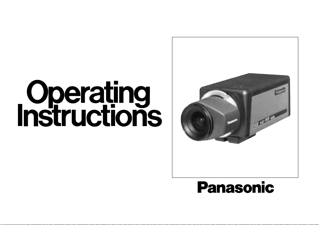
Colour CCTV Cameras
WV-CL830/WV-CL834
(Lens : option)
Before attempting to connect or operate this product,
please read these instructions completely.
Page 2
CAUTION
RISK OF ELECTRIC SHOCK
DO NOT OPEN
CAUTION:
TO REDUCE THE RISK OF ELECTRIC
SHOCK, DO NOT REMOVE COVER (OR
BACK), NO USER SERVICEABLE PARTS
INSIDE.
REFER SERVICING TO QUALIFIED SERVICE
PERSONNEL.
The serial number of this product may be found on the top
of the unit.
You should note the serial number of this unit in the space
provided and retain this book as a permanent record of
your purchase to aid identification in the event of theft.
Model No.
Serial No.
The exclamation point within an equilateral triangle is intended to alert the user
to the presence of important operating
and maintenance (servicing) instructions in the literature accompanying the
appliance.
WARNING:
TO PREVENT FIRE OR ELECTRIC SHOCK HAZARD, DO NOT EXPOSE THIS APPLIANCE TO RAIN OR MOISTURE.
The lightning flash with arrowhead symbol, within an equilateral triangle, is
interned to alert the user to the presence of uninsulated "dangerous voltage" within the product's enclosure that
may be of sufficient magnitude to constitute a risk of electric shock to persons.
ENGLISH VERSION
FOR YOUR SAFETY PLEASE READ THE FOLLOWING TEXT CAREFULLY.
WARNING
THIS APPARATUS MUST BE EARTHED
IMPORTANT
The wires in this mains lead are coloured in accordance with the following
code.
Green-and-yellow: Earth
Blue: Neutral
Brown: Live
As the colours of the wire in the mains lead of this appliance may not
correspond with the coloured markings identifying the terminals in your
plug, proceed as follows.
The wire which is coloured green-and-yellow must be connected to
the terminal in the plug which is marked with the letter E or by the earth
symbol
I or coloured green or green-and-yellow.
The wire which is coloured blue must be connected to the terminal in
the plug which is marked with the letter N or coloured black.
The wire which is coloured brown must be connected to the terminal
in the plug which is marked with the letter L or coloured red.
For U.K.
Page 3
-1-
THIS APPARATUS MUST BE EARTHED.
To ensure safe operation the three-pin plug supplied must be inserted
only into a standard three-pin power point which is effectively earthed
through the normal household wiring. Extension cords used with the
equipment must be three-core and be correctly wired to provide connection to earth. Wrongly wired extension cords are a major cause of
fatalities.
The fact that the equipment operates satisfactorily does not imply that
the power point is earthed and that the installation is completely safe.
For your safety, if in any doubt about the effective earthing of the power
point, consult a qualified electrician.
For Australia
Wij verklaren als enige aansprakelijke, dat het product waarop
deze verklaring betrekking heeft, voldoet aan de volgende normen of andere normatiefve dokumenten, overeenkomstig de
bepalingen van Richtlijnen 73/23/EEC en 89/336/EEC.
Vi erklærer os eneansvarlige for, at dette produkt, som denne
deklaration omhandler, er i overensstemmelse med den
følgende standarder eller andre normative dokumenter i følge
bestemmelserne i direktivene 73/23/EEC og 89/336/EEC.
Vi deklarerar härmed värt fulla ansvar för att den produkt till
vilken denna deklaration hänvisar är i överensstämmelse med
standarddokument, eller andra normativa dokument som
framstölls i Direktiv 73/23/EEC och 89/336/EEC.
Ilmoitamme yksinomaisella vastuullamme, että tuote, jota tämä
ilmoitus koskee, noudattaa seuraavia standardeja tai muita
ohjeellisia asiakirjoja, jotka noudattavat direktiivien 73/23/EEC
ia 89/336/EEC. säädöksiä.
Vi erklærer oss alene ansvarlige for at produktet som denne
erklæringen gjelder for, er i overensstemmelse med følgende
normer eller andre normgivende dokumenter som fælger
bestemmelsene i direktiven 73/23/EEC og 89/336/EEC.
We declare under our sole responsibility that the product to
which this declaration relates is in conformity with the standards or other normative documents following the provisions of
Directives EEC/73/23 and EEC/89/336.
Nosotros declaramos bajo nuestra única responsabilidad que
el producto a que hace referencia esta declaración està conforme con las normas u otros documentos normativos siguiendo las estipulaciones de la directivas CEE/73/23 y CEE/89/336.
Noi dichiariamo sotto nostra esclusiva responsabilità che il
prodotto a cui si riferisce la presente dichiarazione risulta conforme ai seguenti standard o altri documenti normativi conformi
alle disposizioni delle direttive CEE/73/23 e CEE/89/336.
Wir erklären in alleiniger Verantwortung, daß das Produkt, auf
das sich diese Erklärung bezieht, mit der folgenden Normen
oder normativen Dokumenten übereinstimmt. Gemäß den
Bestimmungen der Richtlinite 73/23/EEC und 89/336/EEC.
Nous déclarons sous notre seule responsabilité que le produit
auquel se référe cette déclaration est conforme aux normes ou
autres documents normatifs conformément aux dispositions de
la directive 73/23/CEE et 89/336/CEE.
Page 4

-2-
CONTENTS
PREFACE ...................................................................................................................................................................... 2
FEATURES .................................................................................................................................................................... 2
PRECAUTIONS ............................................................................................................................................................. 3
MAJOR OPERATING CONTROLS AND
THEIR FUNCTIONS ...................................................................................................................................................... 4
CONNECTIONS ............................................................................................................................................................ 7
FOCUS OR BACK FOCAL ADJUSTMENT .................................................................................................................... 12
INSTALLATION OF CAMERA ....................................................................................................................................... 13
SETUP ........................................................................................................................................................................... 14
1. CAMERA SET UP MENU ....................................................................................................................................... 14
2. SETUP OPERATION .............................................................................................................................................. 16
SETTING PROCEDURES .............................................................................................................................................. 19
PREVENTION OF BLOOMING AND SMEAR ................................................................................................................ 36
SPECIFICATIONS ......................................................................................................................................................... 37
STANDARD ACCESSORIES ......................................................................................................................................... 38
Page 5

1. The following functions are built in.
(1) Auto Light Control (ALC)/Electronic Light
Control (ELC)
(2) Back Light Compensation (Auto: Factory pre-
set, Manual: Manual photometric measuring
area set)
(3) Various External Sync Functions, including
Gen-Lock
(4) Auto/Manual White Balance Function
(5) Electronic Shutter Function
2. Signal-to-noise ratio of 50 dB
3. Minimum illumination of 1.5 lux (0.15 footcandle)
with F 1.4 lenses.
4. Minimum illumination of 0.5 lux (0.05 footcandle)
with Panasonic aspherical high speed (F0.75)
lenses.
5. 480 lines of horizontal resolution
els (picture elements), and digital signal processing
LSI's. This model offers cutting-edge technology for
advanced video surveillance.
-3-
PREF ACE
Panasonic's WV-CL830 series colour digital camera
introduces a new level of high picture quality and high
resolution through the use of a 1/2-inch frame interline
transfer CCD image sensor having 771 horizontal pix-
FEATURES
6. High quality picture:
(a) 2H type vertical enhancer for greater picture
sharpness
(b) Chroma averaging circuit for better colour sig-
nal to noise ratio
(c) Minimum of aliasing on fine objects
(d) Expanded dynamic range by use of knee cir-
cuit
(e) Highlight aperture correction for greater pic-
ture detail of bright object
7. Ability to shoot indoor scenes with fixed iris lens by
use of Electronic Light Control (ELC) function.
8. Selectable electronic sensitivity enhancing modes
including : AUTO, MANUAL and OFF
9. Built in Digital Motion Detector
Page 6

1. Do not attempt to disassemble the camera.
To prevent electric shock, do not remove screws
or covers.
There are no user serviceable parts inside. Ask a
qualified service person for servicing.
2. Handle the camera with care.
Do not abuse the camera. Avoid striking, shaking,
etc. The camera could be damaged by improper
handling or storage.
3. Do not expose the camera to rain or moisture,
or try to operate it in wet areas.
Turn the power off immediately and ask a qualified
service person for servicing. Moisture can damage
the camera and also create the danger of electric
shock.
4. Do not use strong or abrasive detergents when
cleaning the camera body.
Use a dry cloth to clean the camera when dirty.
In case the dirt is hard to remove, use a mild
detergent and wipe gently.
5. Clean the CCD faceplate with care.
Do not clean the CCD with strong or abrasive
detergents. Use lens tissue or a cotton tipped
applicator and ethanol.
6. Never face the camera towards the sun.
Do not aim the camera at bright objects. Whether
the camera is in use or not, never aim it at the sun
or other extremely bright objects. Otherwise,
blooming or smear may be caused.
7. Do not operate the camera beyond the
specified temperature, humidity or power
source ratings.
Use the camera under conditions where temperature is between
−10°C - +50°C (14°F - 122°F), and
humidity is below 90%. The input power source is
220 - 240V AC 50Hz for WV-CL830 and DC
12V/AC 24V for WV-CL834.
-4-
PRECAUTIONS
Page 7

MAJOR OPERATING CONTROLS AND THEIR FUNCTIONS
-5-
WV-
CP650
Hi-Z G/L 75Ω
AC 24V
IN
DC 12V
IN
1
2
VIDEO OUT
POWER
ALARM OUT
GND
GND
GEN-LOCK
VIDEO OUT
POWER
ALARM OUT
GND
220 - 240V 50Hz
GEN-LOCK
<WV-CL830>
<WV-CL834>
MAJOR OPERATING CONTROLS AND THEIR FUNCTIONS
Slide the panel to the left until it locks.
Page 8

q Auto Iris Lens Connector
This connector is used to connect with the auto iris
lens by a 4-pin male connector that is supplied as
a standard accessory (Part No. YFE4191J100).
w Back Focal Adjusting Ring
This ring is used to adjust the back focal length or
picture focus. Rotate this ring clockwise for a Cmount lens or counterclockwise for a CS-mount
lens.
e Lens (Option)
r Camera Mounting Screw Hole
This hole is used to mount the camera onto a
mounting bracket.
t Down Button ( )
This button is used to move the cursor downward.
It is also used to select items in the CAM SET UP
menu.
y Right Button ( )
This button is used to move the cursor to the right.
It is also selects the mode and can be used to
adjust some levels.
u Left Button ( )
This button is used to move the cursor to the left. It
also selects the mode and can be used to adjust
some levels.
i Up Button ( )
This button is used to move the cursor upward. It
is also used to select items in the CAM SET UP
menu.
o Set Button ( )
This button is used to activate an item selected in
the CAM SET UP menu.
!0 Gen-lock Termination Switch (Hi-Z, G/L 75Ω)
Set this switch to Hi-Z when a gen-lock video input
signal is looped through. In all other cases, set this
switch to 75Ω.
!1 Power indicator
This indicator lights up when the power of this
camera is on.
!2 Gen-lock Input Connector (GEN-LOCK)
This connector is used to connect an external system for synchronization.
-6-
Page 9

!3 Video Output Connector (VIDEO OUT)
This connector is used to connect with the VIDEO
IN connector of the monitor.
!4 Power Cord Socket
This socket is used to connect the power cord
(supplied as a standard accessory).
!5 Alarm Output Terminal (ALARM OUT/GND)
This terminal is used to connect to the ALARM
INPUT connector (terminal) of an external equipment. When this camera detects motion, the alarm
output signal is supplied to the connected external
equipment.
(Open collector output: 16V DC 100mA max.)
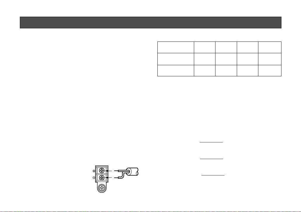
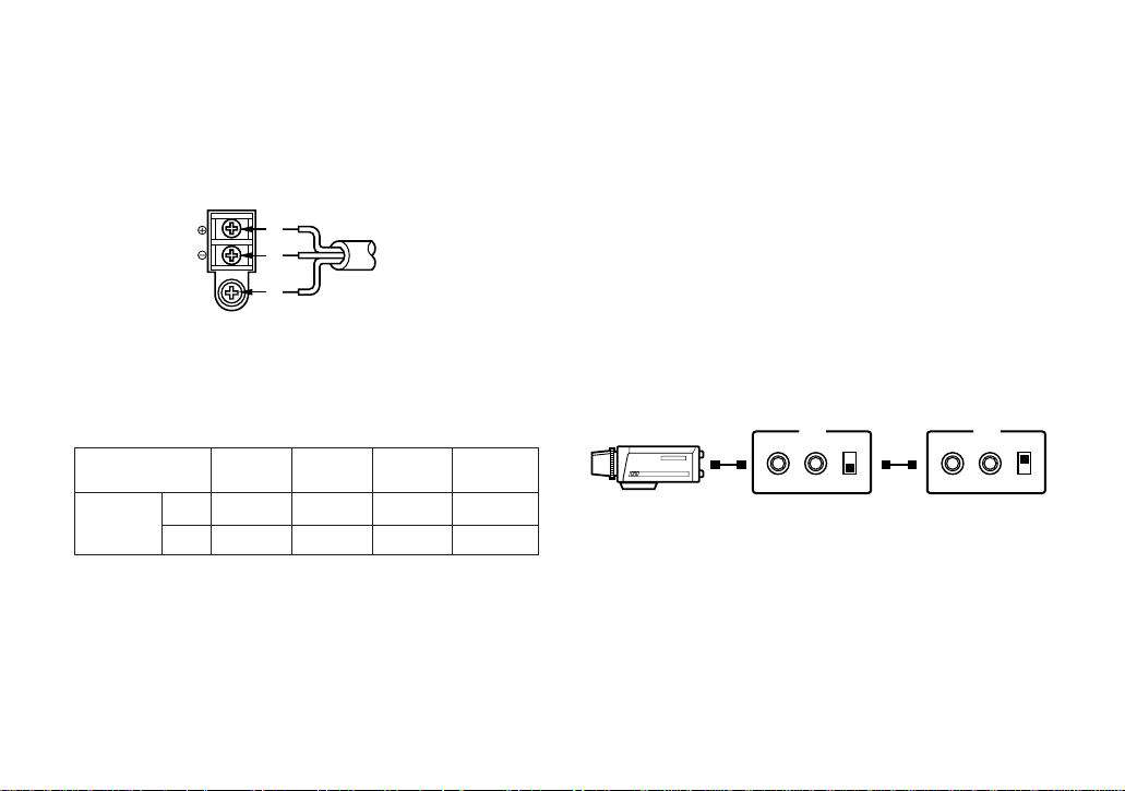
!6 AC/DC Compatible Input Terminal
(DC 12V IN/AC 24V IN)
This terminal is for connecting the 12 V DC or 24 V
AC power supply cord.
-7-
Caution:
Connect to 12V DC (10.5V-16V) or 24V AC
(19.5V-28V) class 2 power supply only.
Make sure to connect the grounding lead
to the GND terminal when the power is
supplied from a 24V AC power source.
Page 10
Copper wire #24 #22 #20 #18
size (AWG) (0.22mm2) (0.33mm2) (0.52mm2) (0.83mm2)
Resistance 0.078 0.050 0.030 0.018
Ω/m
Resistance 0.026 0.017 0.010 0.006
Ω/ft
-8-
A. WV-CL830 (220 - 240V AC 50Hz)
1. Connect the AC power cord (supplied as standard
accessory) to the power cord socket of the camera.
2. Connect the AC power cord to an electrical outlet
of 220 - 240V AC 50 Hz.
Notes:
• Connect the power cord firmly.
• The power cord should be long enough for panning and tilting.
If the cable is too short, the power cord plug may
pulled off the camera when the camera pans or
tilts.
B. WV-CL834 (12V DC/24V AC)
The WV-CL834 has an AC/DC compatible input terminal. The 12V DC or 24V AC power supply cord can be
connected to this terminal. The camera detects the
power source automatically.
1. 12 V DC Power Supply
Connect the power cord to
the AC/DC compatible
input terminal on the rear
panel of the camera.
Resistance of copper wire [at 20°C (68°F)]
AC 24V
IN
DC 12V
IN
1
2
GND
12 VDC
(10.5 V - 16 V)
• Calculation method of maximum cable length
between camera and power supply.
10.5V DC ≤ V
A − (R x 0.42 x L) ≤ 16V DC
L : Cable length (meter)
R : Resistance of copper wire (Ω/meter)
V
A : DC output voltage of power supply unit
V
A − 12
L standard = (meters)
0.42 x R
V
A − 16
L minimum = (meters)
0.42 x R
V
A − 10.5
L maximum = (meters)
0.42 x R
CONNECTIONS
Page 11
2. 24 V AC Power Supply
Connect the power cable to the AC/DC compatible
input terminal on the rear panel of the camera.
Copper wire #24 #22 #20 #18
size (AWG) (0.22mm2) (0.33mm2) (0.52mm2) (0.83mm2)
Length (m) 95 150 255 425
of Cable
(Approx.) (ft) 314 495 842 1 403
Recommended wire gauge sizes for 24V AC line.
AC 24V
IN
DC 12V
IN
1
2
GND
24 VAC, 50 Hz
(19.5 V - 28 V)
-9-
Video Cable
1. It is recommended to use a monitor whose resolution is at least equal to that of the camera.
2. Set the termination switch to the 75
Ω position on
the last monitor.
A. Use a 75Ω coaxial cable.
B. Set the termination switch to the 75Ω position
on the last monitor and to the Hi-Z position on
the other monitors. Do not change the positions after setting.
C. The maximum extensible coaxial cable length
between the camera and the monitor is shown
below.
OUTIN 75Ω
Hi-Z
VIDEO
OUTIN 75Ω
Hi-Z
VIDEO
Monitor
Monitor
Page 12

-10-
Type of RG-59/U RG-6/U RG-11/U RG-15/U
coaxial cable (3C-2V) (5C-2V) (7C-2V) (10C-2V)
Recommended (m) 250 500 600 800
maximum
cable length (ft) 825 1 650 1 980 2 640
3. Wiring precautions:
• Do not bend the coaxial cable into a curve whose
radius is smaller than 10 times the cable’s diameter.
• Never staple the cable even if with circular staples. Impedance mismatching will occur.
• Never crush or pinch the cable.
All of the above will change the impedance of the
cable and cause poor picture quality.
Page 13
-11-
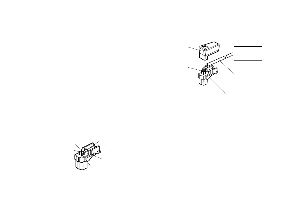
Installation of Auto Iris Lens Connector
Install the lens connector (YFE4191J100) when using a
video drive ALC lens.
The installation should be made by qualified service personnel or system installers.
(1) Cut the iris control cable at the edge of the lens
connector to remove the existing lens connector
and then remove the outer cable cover as shown
in the diagram below.
The pin assignment of the lens connector is as follows:
Pin 1: Power source; +9V DC, 50mA Max.
Pin 2: Not used
Pin 3: Video signal; 1.3 V[p-p]/40 kΩ
Pin 4: Shield, ground
Pin 3
Pin 4
Pin 2
Rib
Pin 1
Note: When the iris control cable is too thick to
lock the connector cover with the connector
base, cut off the rib on the connector.
(Select VIDEO for LENS DRIVE of the CAM
SET UP menu.)
(2) After connection, assemble the lens connector as
follows.
Automatic
Iris Lens
Iris Control
Cable
Connector
Heat
Shrinkable
Tubes
Connector
Cover
Page 14

Caution for Mounting the Lens
The lens mount should be a C-mount or CS-mount (1”32UN) and the lens weight should be less than 450
g
(0.99 lbs). If the lens is heavier, both the lens and camera should be secured by using the supporter.
The protrusion at the rear of the lens should be as
shown below:
C-mount: Less than 11 mm (7/16”)
CS-mount: Less than 6 mm (1/4”)
-12-
1
2
Screws
Back Focal
Adjusting Ring
Mounting the Lens
Caution:
Before you mount the lens, loosen the two screws
on the ring, and rotate this ring clockwise until it
stops. If the ring is not at the end, the inner glass
or CCD image sensor may be damaged.
1. Mount the lens by turning it clockwise on the lens
mount of the camera.
2. Connect the lens cable to the auto iris lens connector on the side of the camera.
Page 15

The following adjustment should be made by qualified
service personnel or system installers.
1. Loosen the screws on the back focal adjusting
ring.
2. Turn the back focal adjusting ring to the desired
position.
Caution: When the C-mount lens is mounted, do
not rotate the ring counterclockwise by force
after it stops. If the ring is rotated by force, the
inner lens or CCD image sensor may be damaged.
3. Tighten the screws on the back focal adjusting
ring.
Focus adjust for
C-mount lens
Focus adjust for
CS-mount lens
-13-
Screws
Back Focal
Adjusting Ring
FOCUS OR BACK FOCAL ADJUSTMENT
Page 16

• Mounting from the bottom
This camera is designed to be mounted from the
bottom, as shown below. The mounting hole is a
standard photographic pan-head screw size (1/4”
- 20).
• Mounting from the top
Remove the mount adapter from the bottom of the
camera by removing the two fixing screws. Attach
the mount adapter to the top as shown in the diagram, then mount the camera on the mounting
bracket.
Make sure that the two original fixing screws are
used when mounting the mount adapter as longer
length screws may damage inner components.
-14-
Fixing Screws
Mount Adapter
<Mounting at top>
<Mounting at bottom>
INSTALLATION OF CAMERA
Page 17

-15-
1. CAMERA SETUP MENU
This camera utilizes a user setup menu that is displayed on-screen.
The setup menu contains various items that form a tree-type structure as shown below.
It is described in the following section : “2. SETUP OPERATION”.
CAM SET UP
Camera
ID
ON/OFF
Camera
ID
Editing
Camera ID
Display
Position
INT
Manual
Selection
AGC
ON/OFF
Electronic
Sensitivity
Enhancement
OFF/ON
VBS
Automatic
Selection
H. Phase
SC. Phase
Manual
Adjustment
H. Phase
Manual
Adjustment
V. Phase
Manual
Adjustment
VS
Automatic
Selection
SYNC
INT/LL
LL
Manual
Selection
VD2
Automatic
Selection
SET UP DISABLE → SET UP ENABLE →
SET UP
PRESET ON
(
Back Light
Compensation
)
Manual
Level
Selection
PRESET
OFF
Light
Control
ALC ELC
Manual
Mask Area
Selection
PRESET ON
(
Back Light
Compensation
)
Manual
Level
Selection
PRESET
OFF
Shutter
Speed
Manual
Mask Area
Selection
Page 18

-16-
Manual
Level
Adjustment
Motion
Detector
OFF/ON
Lens Drive
Signal
Selection
DC Video
Special
menu
Detection
Level
Adjustment
Detection
Masking Area
Selection
Upside
down
Chroma
Gain
AP
Gain
Pedestal
Manual
Level
Adjustment
Manual
Mask Area
Selection
Manual
Mask Area
Selection
White
Balance
ATW AWC
Page 19

-17-
Left Button
Set Switch
Right Button
Down Button
Up Button
Up Button (): This button is used to move the
cursor upwards. Use this button to
select an item or adjust the parameters.
Down Button (): This button is used to move the
cursor downwards. Use this button to select an item or adjust the
parameters.
Right Button (): This button is used to move the
cursor to the right. Use this button
to select or adjust the parameters
of the selected item. The parame-
2. SETUP OPERATION
This camera utilizes a user setup menu (CAM SET UP)
that is displayed on the monitor.
To set items on the CAM SET UP menu, use the following buttons on the side panel.
ter changes each time this button
is pressed.
Left Button (): This button is used to move the
cursor to the left. Use this button
to select or adjust the parameters
of the selected item. The parameter changes each time this button
is pressed.
Set Button (): This button is used to set the
determined parameter. If the item
has its own setting menu ( indicates that the setting menu
exists), press this button to display the setting menu.
• All Reset Operation
All Reset allows you to reset all setup menu items to
the factory settings if you are unsure about the correct
settings. Proceed as follows:
(1) Make sure that the CAM SET UP menu is not dis-
played (a camera picture is displayed).
(2) While pressing both and , press for a
few seconds. The words ALL RESET momentarily
appear on the monitor.
At this time all adjustments and parameters are
reset to the factory default settings.
Page 20

** CAM SET UP **
CAMERA ID OFF
ALC/ELC ALC
SHUTTER OFF
AGC ON
SENS UP OFF
SYNC INT
WHITE BAL ATW
MOTION DET OFF
LENS DRIVE DC
END SET UP DISABLE
↵↵↵↵
-18-
The CAM SET UP menu appears on the monitor as
shown above.
Check the current settings on the menu.
Refer to the sections below for a detailed description of
menu items. If you decide not to make any changes
after checking the current settings, move the cursor to
END at the start of the bottom line, and press to
close the CAM SET UP menu and return to normal
camera picture mode.
Note: If no button is pressed for 6 minutes while the
CAM SET UP menu or any other setting menu is
displayed, displaying the menu is automatically
canceled and the mode returns to the normal camera picture.
• Opening the Setup Menu
Press and hold down for a second or longer.
• Editing the CAM SET UP Menu
Important Notices:
When the words SET UP DISABLE appear on the
bottom line of the CAM SET UP menu, you cannot
change the currently active settings. This is to prevent accidental changing of the settings.
To edit the CAM SET UP menu (change settings), use
and or and to move the cursor to SET
UP DISABLE in the bottom line.
Press . SET UP DISABLE changes to SET UP
ENABLE. Move the cursor to END, then to the item(s)
you want to change.
** CAM SET UP **
CAMERA ID OFF
ALC/ELC ALC
SHUTTER OFF
AGC ON
SENS UP OFF
SYNC INT
WHITE BAL ATW
MOTION DET OFF
LENS DRIVE DC
END SET UP DISABLE
↵↵↵↵
Blinking
Page 21

-19-
• Editing the SPECIAL menu
To edit the SPECIAL menu (change settings), proceed
as for editing the CAM SET UP menu above.
Move the cursor to END after the words SET UP
ENABLE appear. Then press and simultaneously for 2 seconds or longer.
The SPECIAL menu appears on the monitor. Select the
item to be changed and change the setting as
described for the CAM SET UP menu.
Important Notice:
When the cursor is moved to END and the CAM
SET UP menu closed after changing the parameters, the new values are stored in the EEPROM
(Electric Erasable and Programmable Read Only
Memory). These values remain valid until new values are stored, even if the power of the camera is
off.
** CAM SET UP **
CAMERA ID OFF
ALC/ELC ALC
SHUTTER OFF
AGC ON
SENS UP OFF
SYNC INT
WHITE BAL ATW
MOTION DET OFF
LENS DRIVE DC
END SET UP DISABLE
↵↵↵↵
** CAM SET UP **
CAMERA ID OFF
ALC/ELC ALC
SHUTTER OFF
AGC ON
SENS UP OFF
SYNC INT
WHITE BAL ATW
MOTION DET OFF
LENS DRIVE DC
END SET UP ENABLE
↵↵↵↵
** SPECIAL **
UP SIDE DOWN OFF
CHROMA GAIN ....I....
AP GAIN ....I....
PEDESTAL .I.......
- +
CAMERA RESET PUSH SW
RET END
Page 22

0123456789
ABCDEFGHIJKLM
NOPQRSTUVWXYZ
().,'":;&#!?=
+-*/%$ДЬЦЖСЕ
SPACE
POSI RET END RESET
................
-20-
1. Camera Identification (CAMERA ID)
Setting
You can use the camera identification (CAMERA ID) to
assign a name to the camera. The camera ID consists
of up to 16 alphanumeric characters. You can select
whether to have the camera ID displayed on the monitor screen or not.
To edit the CAMERA ID
1. Move the cursor to the CAMERA ID parameter.
2. Press . The CAMERA ID menu appears. The
cursor on the letter “0” starts blinking.
3. Move the cursor to the character you want to
change by pressing / / / .
4. After selecting the character, press . The
selected character appears in the editing area.
(The pointer in the editing area moves to the right
automatically at this moment.)
5. Repeat the steps above until all characters are
edited.
To enter a blank space in the CAMERA ID
Move the cursor to SPACE and press .
To edit a specific character in the CAMERA ID
1. Move the cursor to the editing area by pressing
.
** CAM SET UP **
CAMERA ID OFF
ALC/ELC ALC
SHUTTER OFF
AGC ON
SENS UP OFF
SYNC INT
WHITE BAL ATW
MOTION DET OFF
LENS DRIVE DC
END SET UP ENABLE
↵↵↵↵
SETTING PROCEDURES
Character Cursor
Pointer
Character
Area
Command
Editing
Area
CAMERA ID menu
Page 23

-21-
2. Move the pointer to the character to be edited by
pressing or . Then move the cursor to the
character area and select a new character.
3. Press to determine the CAMERA ID.
To erase all characters in the editing area
Move the cursor to RESET and press . All characters in the editing area disappear.
To determine the display position of the CAMERA
ID
1. Move the cursor to POSI, and press . The display shown below appears and the CAMERA ID
starts blinking.
Blinking
2. Move the CAMERA ID to the desired position by
pressing / / / .
3. Press to fix the position of the CAMERA ID.
The mode returns to the previous CAMERA ID
menu.
Notes:
• The CAMERA ID stops at the edges of the
monitor screen.
• The CAMERA ID moves faster if any of /
/ / is kept pressed for a second or
longer.
To return to the CAM SET UP menu
Move the cursor to RET and press . The CAM SET
UP menu appears.
2. Light Control Setting (ALC/ELC)
You can select the mode for adjusting the lens iris.
The modes are as follows:
ALC: Select this mode when an auto iris lens (ALC
lens) is used with this camera.
ELC: Select this mode when a fixed iris lens or manual
iris lens is used with this camera.
WV-CL830
** CAM SET UP **
CAMERA ID OFF
ALC/ELC ALC
SHUTTER OFF
AGC ON
SENS UP OFF
SYNC INT
WHITE BAL ATW
MOTION DET OFF
LENS DRIVE DC
END SET UP ENABLE
↵↵↵↵
Page 24

-22-
1. Move the cursor to the ALC/ELC parameter.
2. Select ALC or ELC.
Cautions:
1. Under bright lighting conditions such as outdoors,
use an ALC type lens because the ELC control
range is not wide enough under these conditions.
2. Use an ALC type lens if phenomena below occur:
• Strong smear and/or blooming on highlight
objects such as spotlight or sunlight from windows.
• Noticeable flicker in the picture and/or colour
rendition variations.
3. If ELC is selected, SHUTTER is not available.
Back Light Compensation (BACK LIGHT COMP)
Back light compensation is available in for both the
ALC and ELC mode. It eliminates by strong background lighting which makes the camera picture dark,
such as a spotlight. You can select one of two modes
(PRESET ON or PRESET OFF) of back light compensation.
2-1. ALC Mode with PRESET ON
In normal use the important object in a scene is placed
in the centre of the monitor’s screen. In the factory
setup mode, more photometric weight is given to the
centre of the screen (where the important object is
located) than to the edge of the picture (where a bright
back light would most likely be located). In this mode,
even though the backlight may vary, the object at the
centre of the screen can be still be clearly seen.
Note: If ELC is selected, set LEVEL according to this
procedure.
** CAM SET UP **
CAMERA ID OFF
ALC/ELC ALC
SHUTTER OFF
AGC ON
SENS UP OFF
SYNC INT
WHITE BAL ATW
MOTION DET OFF
LENS DRIVE DC
END SET UP ENABLE
↵↵↵↵
1. Press after selecting ALC, the ALC CONT
menu appears.
Page 25

-23-
** ALC CONT **
BACK LIGHT COMP
PRESET OFF
MASK SET
LEVEL ...I.....
- +
RET END
↵
** ALC CONT **
BACK LIGHT COMP
PRESET ON
LEVEL ...I.....
- +
RET END
2. Move the cursor to PRESET parameter and select
ON.
The back light compensation is automatically set.
3. If you want to change the video output level (picture contrast), move the “I” cursor for LEVEL and
adjust the level.
4. Move the cursor to RET and press to return to
CAM SET UP menu.
2-2. ALC Mode with PRESET OFF
These modes are effective when the main object in the
scene is not located in the center of the screen and a
source of bright light is located near the centre of the
screen. In these modes, the picture is divided into 48
corresponding areas mask the light to keep the clarity
of the picture.
Note: If ELC is selected, set MASK SET and LEVEL
according to this procedure.
1. Move the cursor to PRESET parameter and select
OFF.
The items MASK SET appears on the menu.
** ALC CONT **
BACK LIGHT COMP
PRESET OFF
MASK SET
LEVEL ...I.....
- +
RET END
↵
Page 26

-24-
2. Move the cursor to MASK SET and press .
The 48 mask areas appear on the monitor screen.
The cursor is blinking in the top left corner of the
screen.
Blinking
Blinking
5. After masking is completed, press for 2 seconds or longer. The ALC CONT menu appears.
6. If you want to change the video output level (picture contrast), move the “I” cursor for LEVEL and
adjust the level.
3. Move the cursor to the area where backlight is
bright, and press to mask that area. The mask
turns white. (When the cursor is moved on an area
that has already been masked, the mask and cursor start blinking.)
4. Repeat step 1 to 3 to mask the desired area. To
cancel masking, move the cursor to that area and
press .
Blinking
Turns to white
Page 27

-25-
7. Move the cursor to RET and press to return to
the CAM SET UP menu. (To return to the camera
picture, move the cursor to END and press ).
Caution: When an auto iris lens requiring a DC
control signal is used, the lens iris is fully
opened in ELC mode.
3. Shutter Speed Setting (SHUTTER)
Note: If ELC is selected, this item is not available.
You can select an electronic shutter speed of 1/50
(OFF), 1/120, 1/250, 1/500, 1/1 000, 1/2 000, 1/4 000,
or 1/10 000 seconds.
This function is effective to raise the sensitivity in low
light conditions when OFF is selected for ALC.
Move the cursor to the SHUTTER parameter and select
the electronic shutter speed.
The preset values for SHUTTER (electronic shutter
speed) change by pressing or as follows:
** CAM SET UP **
CAMERA ID OFF
ALC/ELC ALC
SHUTTER OFF
AGC ON
SENS UP OFF
SYNC INT
WHITE BAL ATW
MOTION DET OFF
LENS DRIVE DC
END SET UP ENABLE
↵↵↵↵
OFF (1/50) 1/120
1/10000 1/4000 1/2000 1/1000
1/250 1/500
Page 28

-26-
4. Gain Control Setting (AGC ON/OFF)
You can set the gain (brightness level portion of an
image) to automatic level adjustment (ON) or fixed
level(OFF).
Move the cursor to the AGC parameter and select
automatic level adjustment (ON) or fixed level (OFF).
5. Electronic Sensitivity Enhancement
(SENS UP)
There are two modes for SENS UP.
AUTO: If you select x32 AUTO, for example, the
sensitivity is raised automatically to x32 max.
When AUTO is selected, AGC is automatically
set to ON.
FIX: If you select x32 FIX, for example, the sensi-
tivity is raised to just x32.
Move the cursor to the SENS UP parameter and select
the parameter for electronic sensitivity enhancement.
The preset values for SENS UP (electronic sensitivity
enhancement) change by pressing or as follows:
** CAM SET UP **
CAMERA ID OFF
ALC/ELC ALC
SHUTTER OFF
AGC ON
SENS UP OFF
SYNC INT
WHITE BAL ATW
MOTION DET OFF
LENS DRIVE DC
END SET UP ENABLE
↵↵↵↵
** CAM SET UP **
CAMERA ID OFF
ALC/ELC ALC
SHUTTER OFF
AGC ON
SENS UP OFF
SYNC INT
WHITE BAL ATW
MOTION DET OFF
LENS DRIVE DC
END SET UP ENABLE
↵↵↵↵
X2 AUTO
OFF
X4 AUTO X6 AUTO X10 AUTO
X16 AUTO
X32 AUTO X2 FIX
X6 FIX X10 FIX X16 FIX X32 FIX
X4 FIXOFF
Page 29

-27-
Important Notices:
1. The priority for the sync modes is as follows.
1. Multiplexed Vertical Drive (VD2) (Highest priority)
2. Line-lock (LL)
3. Colour Composite Video or Blackburst Signal
(VBS)
4. B/W Composite Video or Composite Sync
Signal (VS)
5. Internal Sync (INT) (Lowest priority)
2. When the internal sync mode is to be used, select
INT. No gen-lock input signal should be supplied
to the Gen-lock Input Connector on the rear panel.
3. Whenever the multiplexed vertical drive pulse
(VD2) is supplied to the camera from an external
equipment such as a Matrix Switcher, the camera
sync mode is automatically switched to the VD2
mode.
4. When the VBS or VS gen-lock mode is to be used
select INT from this menu and supply the gen-lock
input signal to the Gen-lock Input Connector on
the rear panel.
5. The VBS gen-lock mode has its own menu for horizontal and subcarrier phase adjustments. When
the cable length of the video output or the genlock input is changed, the horizontal and subcarrier phase must be re-adjusted.
6. Synchronization Setting (SYNC)
You can select internal sync mode (INT) or line-lock
mode (LL). Additionally, this model accepts the VBS
signal (colour composite video or blackburst signal)
and VS signal (B/W composite video or composite
sync signal). The VD2 signal (multiplexed vertical drive
signal) with the composite video output signal from
external equipment such as a Matrix Switcher is also
acceptable.
Whenever the VD2 signal is supplied to this camera,
the camera automatically switches to the VD2 sync
mode.
1. Move the cursor to the SYNC parameter and
select line-lock(LL) or internal(INT).
2. Press .
If LL is selected, the SYNC menu appears. (If INT
is selected, the synchronization mode is automatically set to internal sync pulse, and the menu is
not displayed.)
** CAM SET UP **
CAMERA ID OFF
ALC/ELC ALC
SHUTTER OFF
AGC ON
SENS UP OFF
SYNC INT
WHITE BAL ATW
MOTION DET OFF
LENS DRIVE DC
END SET UP ENABLE
↵↵↵↵
Page 30

-28-
3. Confirm that the INT parameter changed to EXT
(VBS) on the menu.
Caution: The gen-lock input signal should meet
the CCIR specifications and should not contain jitter, such as a VTR playback signal, as it
could disturb synchronization.
4. After confirming that the cursor is on EXT (VBS),
press . The phase adjustment menu appears
on the monitor.
6. The VS gen-lock mode has its own menu for horizontal phase adjustments. When the cable length
of the video output or the gen-lock input is
changed, the horizontal phase must be re-adjusted.
7. The line-lock mode has its own menu for line-lock
vertical phase adjustment. If the camera installation is relocated, check the vertical phase adjustment again since the AC line phase may be different.
6-1. VBS Gen-lock Mode (EXT(VBS))
1. Move the cursor to the SYNC parameter and
select INT.
2. Connect the coaxial cable for the blackburst or
composite colour video signal to the gen-lock
input connector.
5. Move the cursor to H PHASE. The cursor starts
blinking.
6. Supply the video output signal of the camera to be
adjusted and the reference gen-lock input signal
to a dual-trace oscilloscope.
7. Set the oscilloscope to the horizontal rate and
expand the horizontal sync portion on the oscilloscope.
** SYNC **
H PHASE ........I
- +
SC COARSE 1(1--4)
SC FINE ....I....
- +
RET END
** CAM SET UP **
CAMERA ID OFF
ALC/ELC ALC
SHUTTER OFF
AGC ON
SENS UP OFF
SYNC INT
WHITE BAL ATW
MOTION DET OFF
LENS DRIVE DC
END SET UP ENABLE
↵↵↵↵
** CAM SET UP **
CAMERA ID OFF
ALC/ELC ALC
SHUTTER OFF
AGC ON
SENS UP OFF
SYNC EXT(VBS)
WHITE BAL ATW
MOTION DET OFF
LENS DRIVE DC
END SET UP ENABLE
↵↵↵↵
Page 31

-29-
8. Adjust the horizontal phase by pressing or
. The adjustable range is 0 - 2.0µs.
9. Move the cursor to SC COARSE. The cursor starts
blinking.
10. Press or to match the colour of the camera’s video signal, when observed at the output of
the Special Effect Generator (SEG) or Switcher, as
closely as possible to the colour of the original
scene. (SC COARSE adjustment can be incremented in steps of 90 degrees (4 steps) by pressing or .)
Note: After the fourth step, the adjustment returns
to the first step.
11. Move the cursor to SC FINE. The cursor starts
blinking.
12. Press or to match the colour of the camera’s video signal, when observed at the output of
the Special Effect Generator (SEG) or Switcher, as
closely as possible to the colour of the original
scene.
The SC FINE adjustment has a range of 90
degrees of color shift.
Notes:
• When the “I” cursor reaches the “+” end, it
jumps back to “−” . At the same time, SC
COARSE is incremented by one step to
enable a continuous adjustment. The reverse
takes place when the “I” cursor reaches the
“−” end.
• When or is kept pressed for a second
or more, the “I” cursor moves quickly.
• For more accurate adjustment, supply both
the original camera video output signal and
the effect output video signal (program output
video signal) of the special effects generator
(SEG) to a vectorscope and compare the
chroma phase of both signals.
• To reset SC COARSE and SC FINE to the values preset at the factory, press or
simultaneously. SC COARSE is reset to the
factory setting.
1 (1 - - 4): 0 degrees
2 (1 - - 4): 90 degrees
3 (1 - - 4): 180 degrees
4 (1 - - 4): 270 degrees
Page 32

-30-
4. After confirming the cursor is on EXT (VS), press
. The phase adjustment menu appears on the
monitor.
6-2. VS Gen-lock Mode (EXT(VS))
1. Move the cursor to the SYNC parameter and
select INT.
2. Connect the coaxial cable for the composite sync
or composite B/W video signal to the gen-lock
input connector.
3. Confirm that the parameter INT changed to EXT
(VS) on the menu.
Caution: The gen-lock input signal should meet
with CCIR specifications and should not contain jitter, such as a VTR playback signal , as
it could disturb synchronization.
5. Move the cursor to H PHASE. The cursor starts
blinking.
6. Supply the video output signal of the camera to be
adjusted and the reference gen-lock input signal
to a dual-trace oscilloscope.
7. Set the oscilloscope to the horizontal rate and
expand the horizontal sync portion on the oscilloscope.
8. Adjust the horizontal phase by pressing or
. The adjustable range is 0 - 2.0µs.
6-3. Line-lock Sync Mode (LL)
Note: The line-lock (LL) sync mode is not available
when the camera operates on DC power.
1. Move the cursor to the SYNC parameter and
select LL.
Note: The settings in this menu can be made only
when the multiplexed vertical drive signal
(VD2) is not supplied to the camera.
** CAM SET UP **
CAMERA ID OFF
ALC/ELC ALC
SHUTTER OFF
AGC ON
SENS UP OFF
SYNC INT
WHITE BAL ATW
MOTION DET OFF
LENS DRIVE DC
END SET UP ENABLE
↵↵↵↵
** CAM SET UP **
CAMERA ID OFF
ALC/ELC ALC
SHUTTER OFF
AGC ON
SENS UP OFF
SYNC EXT(VS)
WHITE BAL ATW
MOTION DET OFF
LENS DRIVE DC
END SET UP ENABLE
↵↵↵↵
** SYNC **
H PHASE ........I
- +
RET END
Page 33

-31-
2. After confirming the cursor is on LL, press .
The vertical phase adjustment menu appears on
the monitor.
3. Move the cursor to COARSE. The cursor starts
blinking.
4. Supply the video output signal of the camera to be
adjusted and the reference camera video output
signal to a dual-trace oscilloscope.
5. Set the oscilloscope to the vertical rate and
expand the vertical sync portion on the oscilloscope.
6. Press or to match the vertical phase for
both video output signals as closely as possible.
(COARSE adjustment can be incremented in 16
steps by 22.5 degrees by pressing or .)
Note: After the sixteenth step, the adjustment
returns to the first step.
7. Move the cursor to FINE. The cursor starts blinking.
8. Press or to match the vertical phase for
both video output signals as closely as possible.
(FINE adjustment can be made up to 22.5 degrees
by pressing or .)
Notes:
• When the “I” cursor reaches the “+” end, it
jumps back to “−”. At the same time, COARSE
is incremented by one step to enable a continuous adjustment. The reverse takes place
when the “I” cursor reaches the “−” end.
• When or is kept pressed for a second
or longer, the “I” cursor moves faster.
1 (1 - - 16): 0 degrees
2 (1 - - 16): 22.5 degrees
16 (1 - - 16): 337.5 degrees
** SYNC **
V PHASE
COARSE 1(1--16)
FINE I........
- +
RET END
Page 34

-32-
• To reset COARSE and FINE to the values preset at the factory, press or simultaneously. COARSE and FINE adjustments are
preset at the factory to zero-crossing of the
AC line phase.
• If the AC line contains noise (spike noise,
etc.), the stability of the vertical phase of the
camera video output signal may be disturbed.
7. White Balance Setting (WHITE BAL)
7-1. Auto-Tracing White Balance Mode (ATW)
You can select one of two modes for white balance
adjustment as follows:
• ATW (Auto Tracing White Balance)
In this mode, the colour temperature is monitored
continuously and thereby white balance is set automatically. The colour temperature range for the
proper white balance is approximately 2 600 - 6
000K. Proper white balance may not be obtained
under the following conditions:
1. The colour temperature is out of the 2 600 6 000K range.
2. When the scene contains mostly high colour
temperature objects, such as a blue sky or
sunset.
3. When the scene is dim.
In these cases, select the AWC mode.
Move the cursor to the WHITE BAL parameter and
select ATW. The white balance of the camera is
automatically set.
** CAM SET UP **
CAMERA ID OFF
ALC/ELC ALC
SHUTTER OFF
AGC ON
SENS UP OFF
SYNC INT
WHITE BAL ATW
MOTION DET OFF
LENS DRIVE DC
END SET UP ENABLE
↵↵↵↵
Page 35

-33-
•
Automatic White Balance Control Mode (AWC)
In this mode, accurate white balance is obtained
within a colour temperature range of approximately 2 300-10 000K.
1. Move the cursor to the WHITE BAL parameter and
select AWC → PUSH SW.
2. Press to start the white balance setup. The
words PUSH SW start blinking to indicate that the
white balance is being set.
Blinking
3. When the white balance setting is completed, the
words PUSH SW stop blinking.
4. When you want to adjust the white balance manually, press to select AWC and press . The
AWC menu appears on the monitor. (When ATW is
selected, pressing displays the ATW menu.)
Fine Adjustment for AWC (ATW) Manually
You can add the detailed setting for white balance setting manually.
1. To set MASK SET, proceed as described in steps
1 to 4 of “ALC mode with PRESET OFF” on page
22.
2. Move the cursor to R.
3. Press or to obtain the optimum amount of
red gain.
4. Move the cursor to B.
5. Press or to obtain the optimum amount of
blue gain.
** CAM SET UP **
CAMERA ID OFF
ALC/ELC ALC
SHUTTER OFF
AGC ON
SENS UP OFF
SYNC INT
WHITE BAL AWC
→
PUSH SW
MOTION DET OFF
LENS DRIVE DC
END SET UP ENABLE
↵↵↵
** CAM SET UP **
CAMERA ID OFF
ALC/ELC ALC
SHUTTER OFF
AGC ON
SENS UP OFF
SYNC INT
WHITE BAL AWC
→
PUSH SW
MOTION DET OFF
LENS DRIVE DC
END SET UP ENABLE
↵↵↵
** CAM SET UP **
CAMERA ID OFF
ALC/ELC ALC
SHUTTER OFF
AGC ON
SENS UP OFF
SYNC INT
WHITE BAL AWC
MOTION DET OFF
LENS DRIVE DC
END SET UP ENABLE
↵↵↵↵
** AWC **
R ....I....
- +
B ....I....
- +
MASK SET
RET END
↵
Page 36

-34-
Note: When you need to set MASK SET, re-adjust to
obtain the optimum amount of red and blue gain.
8. Motion Detector Setting (MOTION DET)
The motion detector detects the moving objects in the
scene by monitoring the brightness level changes. You
can select the level of sensitivity for motion detection.
When this camera is connected to a compatible intelligent CCTV system, the camera transmits an alarm signal by multiplexing it with the video signal.
1. Move the cursor to the MOTION DET parameter
and select ON.
2. Press . The MOTION DETECT menu appears
on the monitor screen.
3. Move the cursor to MASK SET and press . The
MASK SET menu has 48 masks. To set MASK SET,
proceed as described in steps 2 to 4 of “ALC
mode with PRESET OFF” on page 22.
4. Move the cursor to the ALARM parameter and
select ON or OFF to set the alarm in the DISPLAY
MODE.
Note: When the system controller WV-RM70, WV-
CU550 or WV-CU550A is used with this
model, select OFF for ALARM.
5. Move the cursor to DISPLAY MODE and press
to see the current setting. The masks that detect
the brightness changes start blinking.
6. To raise detection sensitivity, press to return to
the MOTION DETECT menu.
7. To obtain the optimum detection level, move the
“I” cursor to adjust the level.
8. Repeat the procedures above to obtain a satisfactory setting.
9. Move the cursor to RET and press to return to
the CAM SET UP menu.
** CAM SET UP **
CAMERA ID OFF
ALC/ELC ALC
SHUTTER OFF
AGC ON
SENS UP OFF
SYNC INT
WHITE BAL AWC
MOTION DET ON
LENS DRIVE DC
END SET UP ENABLE
↵↵↵↵
** MOTION DETECT **
LEVEL ....I....
- +
DISPLAY MODE
ALARM ON
MASK SET
RET END
↵
↵
Page 37

-35-
Notes:
• Masking or adjusting the detection level is needed
to prevent malfunction under the following conditions:
• When shooting an object under flickering fluorescent light or shooting in ELC.
• When leaves or curtains etc. are swayed by the
wind.
• When the object is lighted by lighting equipment
that constantly turns on and off.
• It takes about 0.2 seconds for the alarm signal to
reach the alarm terminal of the VTR after the camera detects the object.
Because the alarm signal is multiplexed on the
video signal, it may be mistakenly interpreted by
other video equipment as a time code signal.
Therefore, when camera is not used in a
Panasonic Intelligent CCTV System select OFF to
prevent the above from occurring.
1. Move the cursor to the LENS DRIVE parameter.
2. Select DC if you are using the auto iris lens that
requires a DC drive signal.
Select VIDEO if you are using the auto iris lens that
requires a video drive signal.
9. Lens Drive Signal Selection (LENS
DRIVE)
This item is used to select the type of auto iris lens
drive signal to be supplied to the lens from the auto iris
lens connector.
** CAM SET UP **
CAMERA ID OFF
ALC/ELC ALC
SHUTTER OFF
AGC ON
SENS UP OFF
SYNC INT
WHITE BAL ATW
MOTION DET OFF
LENS DRIVE DC
END SET UP ENABLE
↵↵↵↵
Page 38

-36-
10. Special Menu (SPECIAL)
This menu lets you adjust and set up the video signal
of the camera to meet your requirements.
Move the cursor to END on the bottom line of the CAM
SET UP menu and press or simultaneously for
2 seconds or longer. The SPECIAL menu appears on
the monitor as shown below.
10-1. Camera Picture Upside Down Positioning
(UP SIDE DOWN)
1. Move the cursor to the UP SIDE DOWN parameter.
2. Select ON when you want to turn the picture
upside down.
** CAM SET UP **
CAMERA ID OFF
ALC/ELC ALC
SHUTTER OFF
AGC ON
SENS UP OFF
SYNC INT
WHITE BAL ATW
MOTION DET OFF
LENS DRIVE DC
END SET UP ENABLE
↵↵↵↵
** SPECIAL **
UP SIDE DOWN OFF
CHROMA GAIN ....I....
AP GAIN ....I....
PEDESTAL .I.......
- +
CAMERA RESET PUSH SW
RET END
10-2. Chroma Level Setting (CHROMA GAIN)
1. Move the cursor to the CHROMA GAIN parameter.
2. While observing the vectorscope or colour video
monitor, move the “I” cursor to adjust the chroma
level.
10-3. Aperture Gain Setting (AP GAIN)
1. Move the cursor to the AP GAIN parameter.
2. While observing the vectorscope or video monitor,
move the “I” cursor to adjust the aperture gain
level.
10-4. Pedestal Level Setting (PEDESTAL)
1. Move the cursor to the PEDESTAL parameter.
2. While observing the waveform monitor/oscilloscope or video monitor, move the “I” cursor to
adjust the pedestal level (black level).
Page 39

-37-
To reset to the factory settings
1. Move the cursor to the CAMERA RESET parameter. The words PUSH SW start blinking.
2. While holding down and , press for 2
seconds or longer. The camera is reset to the factory settings.
To close the SPECIAL menu and return to the CAM
SET UP menu
Move the cursor to RET and press .
To close the SPECIAL menu and return to the
camera picture
Move the cursor to END and press .
When the camera is aimed at a bright light, such as a
spotlight, or a surface that reflects bright light, smear
or blooming may appear. Therefore, the camera
should be operated carefully in the vicinity of extremely
bright objects to avoid smear or blooming.
Bright object
Smear
PREVENTION OF BLOOMING AND SMEAR
Page 40

Pick-up Device: 771 (H) x 582 (V) pixels, Frame Interline Transfer CCD
Scanning Area: 6.4 (H) x 4.8 (V) mm (Equivalent to scanning area of 1/2” pick-up tube)
Scanning: 625 lines/50 fields/25 frames
Horizontal: 15.625 kHz
Vertical: 50 Hz
Synchronization: Internal, Line-locked, External (VS/VBS) or
Multiplexed Vertical Drive (VD2) Selectable
Video Output: 1.0 V[p-p] PAL composite 75 Ω/BNC connector
Horizontal Resolution: 480 lines
Signal-to-Noise Ratio: 50 dB (AGC OFF, weight ON)
Minimum Illumination: 0.5 lx (0.05 footcandle) at F0.75 [Equivalent to 1.5 lx (0.15 footcandle) at F1.4]
Gain Control: Selectable AGC ON or OFF (SET UP MENU)
White Balance: Selectable ATW or AWC (SET UP MENU)
Aperture: Set Variable (SET UP MENU)
Electronic Light Control: Equivalent to continuous variable shutter speed between 1/50 s
and 1/10 000 s
Super D: Selectable On or Off (SET UP MENU)
Electronic Shutter Speed: Selectable 1/50 (OFF), 1/120, 1/250, 1/500, 1/1 000, 1/2 000, 1/4 000,
1/10 000 s
Lens Mount: Selectable C-mount or CS-mount
ALC Lens: Selectable DC or Video
Ambient Operating Temperature: −10°C - +50°C (14°F - 122°F)
Ambient Operating Humidity: Less than 90%
-38-
SPECIFICATIONS
Page 41

-39-
Power Source and WV-CL830: 220 - 240V AC 50 Hz, 4.8W
Power Consumption: WV-CL834: 24V AC 50 Hz, 4.8W
12V DC, 500 mA
Dimensions (without lens): 67 (W) x 55 (H) x 123 (D) mm
[2-5/8” (W) x 2-3/16” (H) x 4-13/16” (D)]
Weights (without lens): WV-CL830: 0.41 kg (0.90 lbs.) (without power cord)
WV-CL834: 0.40 kg (0.88 lbs.)
Weights and dimensions indicated are approximate.
Specifications are subject to change without notice.
STANDARD ACCESSORIES
Body Cap.............................................................................1 pc.
ALC Lens Connector (YFE4191J100)..................................1 pc.
AC Power Cord (for only WV-CL830)...................................1 pc.
Page 42

Matsushita Electric Industrial Co., Ltd.
Central P.O. Box 288, Osaka 530-91, Japan
N1297-0 YWV8QA4823AN Printed in Japan
N 30
 Loading...