

Panasonic WV-BP102 User Manual
Operating
Instructions
CCTV Camera
WV-BP102
rwmwm&KMW^
aiwtrang to c«nra«r « o|i«ata <<k imtirl,
pinM 'iMrt («WM >*«liutl>oni eomeWev

...........................................................................................................For U.S.A .
CAUTION
nSK OF ELECTRIC SHOCK
A
CAUTION:
TO REDUCE THE RISK OF ELECTRIC SHOCK, DO
NOT REMOVE COVER (OR BACK). NO USER SER
VICEABLE PARTS INSIDE.
REFER SERVICING TO QUALIFIED SERVICE
PERSONNEL.
A
SA 1965
SA 1966
WARNING:
TO PREVENT FIRE OR SHOCK HAZARD, DO NOT EXPOSE THIS APPLIANCE TO RAIN OR MOISTURE.
00 AJOT OPEN
The lightning flash with arrowhead
symbol, within an equilateral triangle,
is intended to alert the user to the
presence of uninsulated "dangerous
voltage" within the product's
enclosure that may be of sufficient
magnitude to constitute a risk of elec
tric shock to persons.
The exclamation point within an
equilateral triangle is intended to alert
the user to the presence of important
operating and maintenance (servicing)
instructions in the literature accompa
nying the appliance.
A
Warning:
This equipment generates and uses radio frequency
energy and if not installed and used properly, i.e., in
strict accordance with the instruction manual, may
cause harmful interference to radio communications.
It has been tested and found to comply with the limits
for a Class A computing device pursuant to Subpart
J of Part 15 of FCC Rules, which are designed to pro
vide reasonable protection against such interference
when operated in a commercial environment.
.................................................................................................... For CANADA ,
This digital apparatus does not exceed the Class A
limits for radio noise emissions from digital apparatus
set out in the Radio Interference Regulations of the
Canadian Department of Communications.
The serial number of this product may be found on
the bottom of the unit.
You should note the serial number of this unit in the
space provided and retain this book as a permanent
record of your purchase to aid identification in the
event of theft.
Model No.
Serial No.
_____________________________________
_________________________________

CONTENTS
■PREFACE .................................................................................................
FEATURES ...............................................................................................
PRECAUTIONS ........................................................................................
MAJOR OPERATING CONTROLS AND THEIR FUNCTIONS
CONNECTIONS .......................................................................................
SYSTEM CONNECTION .........................................................................
LENSES
FOCUS OR FLANGE-BACK ADJUSTMENT
INSTALLATION OF CAMERA
PREVENTION OF BLOOMING AND SMEAR
LENS MAINTENANCE AND CLEANING ....
SPECIFICATIONS .....................................................
STANDARD ACCESSORIES ...................................
OPTIONAL ACCESSORIES
......................................................................
.................................
....................................
. 2
. 2
. 3
. 4
. 7
. 9
10
16
17
17
17
18
19
,19

PREFACE
FEATURES
Panasonic’s CCTV Camera WV-BPI02 introduce a new
level of high picture quality through the use of a 1/3
inch interline transfer CCD having 512 horizontal pixels
(picture elements), High performance-to-cost ratio is
achieved through the use of newly developed Sync IC’s
and ability.to shoot indoor scenes with a fixed iris lens
by use of Electronic Light Control (ELC) function.
• Minimum illumination of 0.03 footcandle (0,3 lux) at
Fl.4 and SignaMo-noise ratio of 46 dB by employing
a 1 /3 inch interline transfer CCD image sensor with
512 (H) X 492 (V) pixels.
• 380 lines of horizontal resolution,
• Either optional standard C-mount or Special
C-mount (CS-mount) auto iris control lens can be
used with.
• ■ Selectable auto iris control signal for the lens either
a video signal or DC control signal.
• Switchable Multiplexed Vertical Drive (VD2)
automatically for Gen-lock system.
• Ability to shoot indoor scenes with fixed iris lens by
use of Electronic Light Control (ELC) function.
, • Two power source are available. (12V DC, DC power
supplied from the specified monitor or camera drive
unit.)
-2-

PRECAUTIONS
• Do not attempt to disassemble the camera.
To prevent electric shock, do not remove screws or
cover. There are no user-serviceable parts inside.
Refer servicing to qualified service personnel.
• Handle the camera with care.
Do not abuse the camera. Avoid striking or shaking
it. The camera could be damaged by improper
handling or storage.
• Do not expose the camera to rain or moisture, or
try to operate it in wet areas.
Do take immediate action if ever the camera do
becomes wet. Turn power off and refer servicing to
qualified service personnel. Moisture can damage
the camera and also create the danger of electric
shock.
Never face the camera toward the sun.
Whether the camera is in use or not, never face it
toward the sun. Do use caution when operating the
camera in the vicinity of spot lights or other bright
lights and light reflecting objects.
Do not operate the camera beyond its
temperature, humidity or power source ratings.
Do not use the camera in an extreme environment
where high temperature or high humidity exist. Use
the camera under conditions where temperatures
are within -22°F - 122°F (-30°C - -F50°C), and
humidity is below 90*/..
Caution :
To prevent fire or shock hazard, the UL listed wire
VW-1, style 1007 should be used for the cable for
DC 12V Input Terminal.
CAUTION :
CONNECT THIS TO A DC 12V CLASS 2 POWER
SUPPLY ONLY.
- 3 -
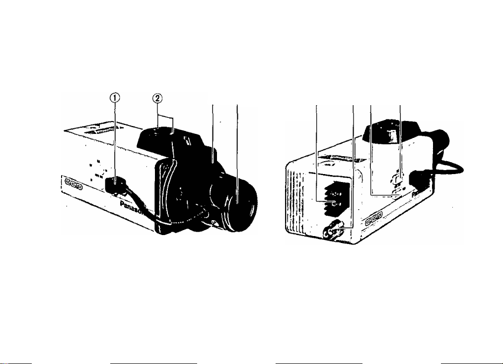
MAJOR OPERATING CONTROLS AND THEIR FUNCTIONS
® ® ® (6)
- 4 -

(1) Auto Iris Lens Connector
This 4-pin female connector supplies the power and
either video signal or DC control signal to the auto
iris lens,
A 4-pin mate connector, which can be mated with
the camera’s female connector, is supplied as a
standard accessory (Part No. YFE4191J100),
This male connector can be installed on lenses
which have incompatible type connector.
See page 14 for installation details.
(2) Camera Mounting Screw Hole
These threaded holes (1/4" - 20) are used to mount
the camera onto a mounting bracket or tripod.
(3) Flange-back Adjusting Ring
This ring is used to adjust the back focal length
or picture focus by rotating this ring to clockwise
for C-mount lens or counterclockwise for special
C-mount (CS-mount) lens.
Cautions :
1. Always set this ring to fully clockwise before
mounting the lens,
2. Do not turn this ring too much to
counterclockwise when the C-mount lens is
mounted as this could damage the inner glass
and CCD image sensor,
(4) Lens (Option)
See pages 10, 11, 12 and. 13 for details on lens
selection.
(5) Lens Selection Switch (AUTO IRIS, DC/VIDEO)
This switch is used to select the supplied auto iris
control signal to the lens from the Auto iris lens
Connector (1),
DC :
Choose this position when the auto iris
control lens requiring DC control signal
such as WV-LA2.8, WV-LA4R5C3, WV-LA6B2,
WV-LA9C3, WV-LA12B2, WV-LA18, WV-LA36,
WV-LA4510, WV-LA608, WV-LA1208,
WV-LZ81/6A, WV-LZ81/10, WV-LZ83/6, is
mounted on the camera.
VIDEO :
Choose this position when the auto iris
control lens requiring video signal such as
WV-LA8B, WV-LA1 6B, WV-LA25B, WV-LA50B,
is mounted on the camera.
- 5 -
 Loading...