

Panasonic WV-BM90 Service Manual
Service
ORDER NO.AVS8903175C8
Manual
Video Monitor
WV-BM90:’
SPECIFICATIONS
. . . . . . . . . . . . . . . . . . . . .
_ .
. . . . . . .
MAJOR OPERATING CONTROLS AND
THEIRFUNCTIONS . . . . . . . . . . . . . . . . . . . . . . . . . . . . . . . . . .
CONECTION
. . . .
.
. . . . .
_
.
.
.
. . . . .
. . .
. . .
OPERATING PROCEDURE
. . . . . _. . . . . . . . . _. _. . . .
CIRCUIT DESCRIPTION
l.MainBoard
. . . . . . . . . . . . . . . . . . . . . . . . . . . . . . . . . . .
2.Control Board
_. _. . _. . . . . . _. _ _. _. . . .
ADJUSTMENT PROCEDURE
. . .
.
. . . . . .
.
. _. .
APPEARANCE OF IC,
TRANSISTER
AND DIODE
. . . . .
LOCATION OF TEST POINTS AND
ADJUSTINGCONTROLS
__........_______._......_..
Panasonic
CONTENTS
1
2
4
5
7
7
11
14
15
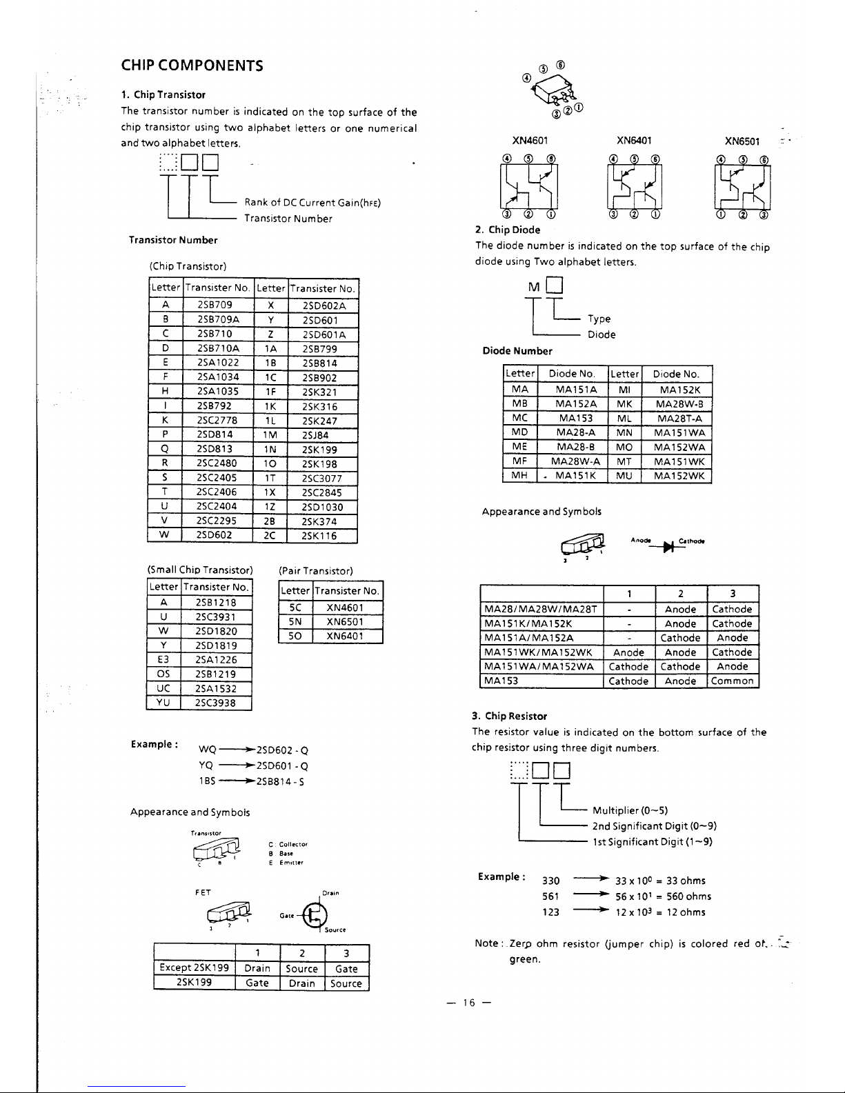
CHIP COMPONENTS
. .
.
. .
. .
. . .
WIRINGDIAGRAM . . . . . . . . . . . . . . . . . . . . . . . . . . . . . . . .
BLOCK DIAGRAM
MAIN BOARD/SWITCH BOARDNOLUME BOARD
.
CONTROL BOARD/CONTROL SUB BOARD
.
CONDUCTOR VIEW
MAIN BOARD/SWITCH BOARDNOLUME BOARD
CONTROL BOARD/CONTROL SUB BOARD
. . . . .
SCHEMATIC DIAGRAM
MAIN BOARD/SWITCH BOARDNOLUME BOARD
CONTROL BOARD/CONTROL SUB BOARD
. . . .
EXPLODED VIEW OF
WV-BM90
. . . .
. . .
REPLACEMENT PARTS LIST
_. . . . . _. . _. _. . .
16
18
19
20
26
24
25
21
27
28
Matsushita Electric Industrial Co., Ltd,.
-I,-
Central P.O. Box 288, Osaka 530-91, Japan
This symbol warns the user that uninsulated voltage
within the unit may have
suificient
magnitude to
cause electric shock. Therefore, it is dangerous to
make any kind of contact with any inside part of
_.
-CAUTIONTO “EDUCE
TUE RI% CIF ELEC
TRIG SHOCK DO
NOT
AEMO’JE
- to”En ,OR BACK
NO
USER
*
SERVICEABLE PARTS
INSlDE
This symbol alerts the user that important literature
FIEFEEI SEAVICING TO CIVALI
concerning the operation and maintenance of this
FIED SERVICL
PERSONNEL
/
unit has been included.
Therefore, it should be read carefully in order to
avoid any problems.
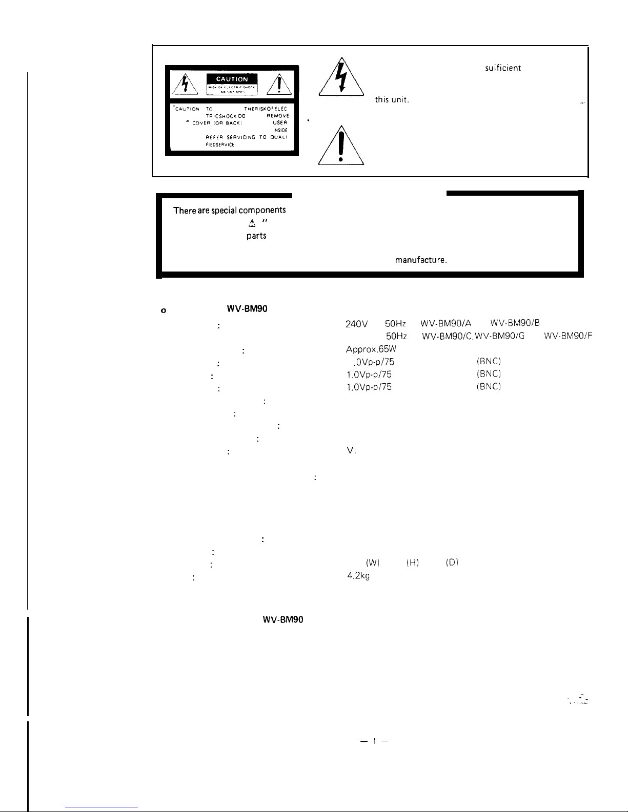
IMPORTANT SAFETY NOTICE
There are special components
used in this equipment which are important for safety. These parts
are indicated by”
A
” mark on the schematic diagram and the replacement parts list. It is essential
that these critical
parts
should be replaced with manufacture’s specified parts to prevent shock,
fire, or other hazards.
Do not modify the original design without permission of
manUfaCtUre.
\
SPECIFICATIONS
0
Video Monitor
WV-BM90
Power Supply
:
24OV
AC
50Hz
for
WV-BMSOIA
and WV-BMSO/B
Power Consumption
:
Camera Input
:
Video Input
:
Video Output
:
Power Supply for Camera
:
Camera Switching
:
Sequential Switching Interval
:
Resolution (Horizontal)
:
Sweep Linearity
:
External Control Connection Terminal
:
Camera Extension Input
:
Alarm Time
:
Dimensions
:
Weight
:
OPTIONAL ACCESSORIES
o Optional Accessory for
WV-BM90
o Camera Extension Unit
220V AC
50Hz
for WV-BMSO/C, WV-BMSOIG and
WV-BM90lF
Approx.65W
1
.OVp-p/75
ohms, composite x 4 (BNC)
l.OVp-p/75
ohms, composite x 1 (BNC)
l.OVp-p/75
ohms, composite x 1 (BNC)
Regulated current multiplex method
Manual/Auto (Sequence) With auto and manual bypass
Adjustable; 1 to 30 sec.
750 lines at center
V:
Less than 7%
H:
Less than 5%
SPOT MONITOR CONTROL IN x 4
RECOVER IN x 1
ALARM CONTROL OUT x 2
REMOTE OUT x 4
RESET OUT x 1
10 pin connector
Adjustable: 2 to 30 sec.
230
(W)
x 240 (H) x 270 (D) mm
4.2kg
WV-83
-
l-

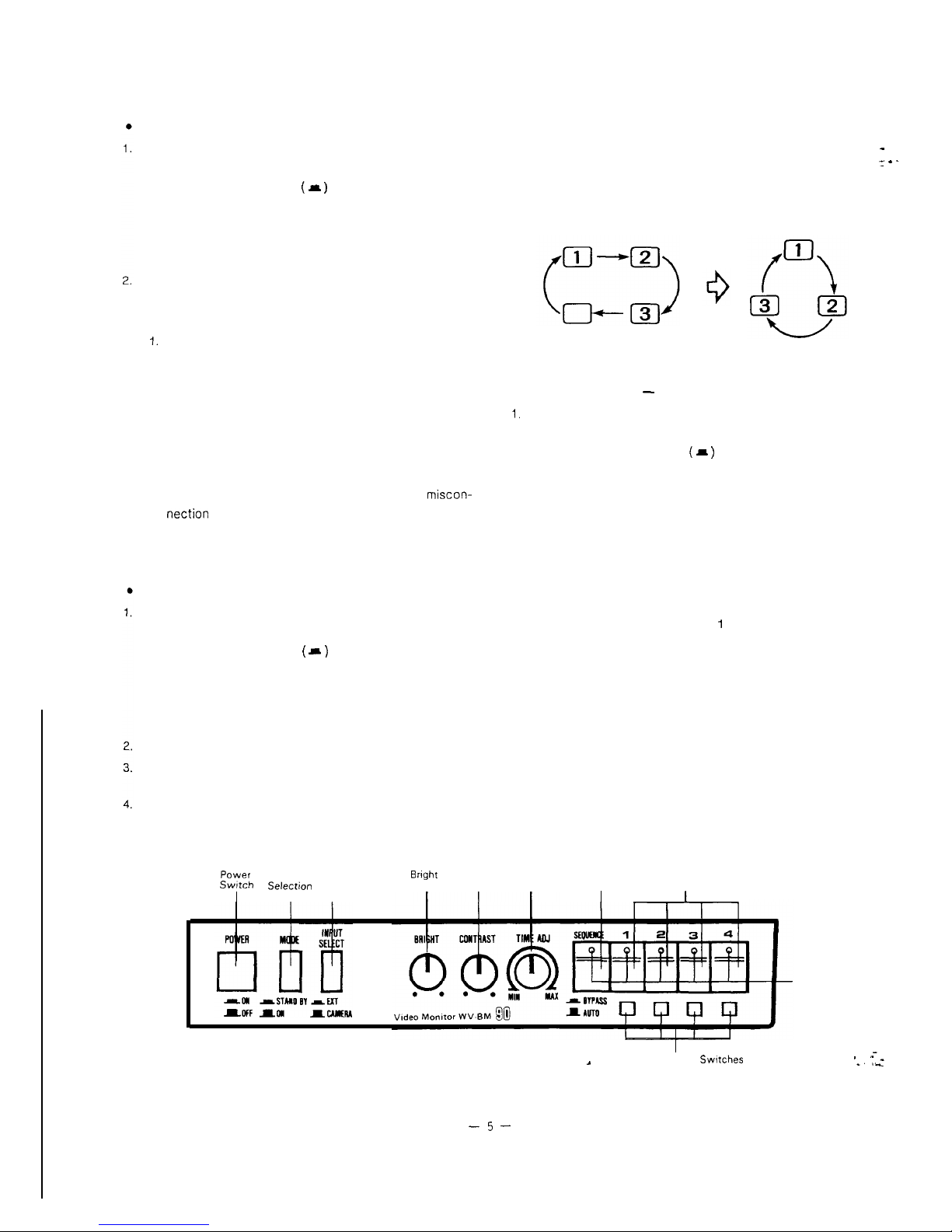
MAJOR OPERATING CONTROLS AND THEIR FUNCTIONS
VIDEO MONITOR
WV-BM90
1 Power Switch (POWER)
This is a push type switch which turns the monitor ON and
OFF.
Push once and the switch remains down
( a )
for turning
on the monitor and cameras,
Sequence and camera number indicator lamps light.
Push again, the switch comes up
( 1 )
for turning off the
monitor and cameras, and the lamps go off.
2 Mode Selection Switch (MODE STANDBY/ON)
This selects the condition of the monitor as;
ON:
The picture of the camera will appear on the monitor.
STANDBY:
The picture of the camera will not appear on the monitor
in the sequence mode, however the picture signal is
provided at Video Output Connector (IO).
The picture of desired camera can be observed by
selecting Camera Selection Switch (6).
3 Input
SelectionSwitch(lNPUTSELECTEXT/CAMERA)
This selects the condition of the monitor as;
EXT:
VTR playback picture connected to Video Input Connector can be observed.
CAMERA:
Camera picture connected to Camera Input Connector
can be observed.
4 Bright Control (BRIGHT)
Turn this control clockwise to increase the picture
brightness.
Contrast Control (CONTRAST)
Turn this control clockwise to increase the picture
contrast.
Time Adjustment (TIME ADJ,
MIN/MAX)
The sequential switching interval can be manually ad-
justed from 1 to 30 seconds by turning this knob.
Sequence Switch (SEQUENCE)
This is a push-push type switch which selects the cameras
in sequential switching mode when the switch is pushed
and its lamp lights. The switching interval can be adjusted
by Time Adjustment (6) from 1 to 30 seconds.
Camera Selection Switches
These are push-push type switches which select the de-
sired camera to observe picture and the lamp of the selected channel lights. When one of these switches is
pushed on, the sequence switch goes off if the sequence
switch has been turned ON.
Bypass Selection Switches (BYPASS/AUTO)
These select the condition of the monitor as;
BY PASS:
The picture of the connected camera will be skipped.
AUTO:
The channel(s) with no camera connection will be automatically skipped.
-2-

10
11
12
13
14
15
Camera Input Connectors (CAMERA INPUT)
The BNC type connectors are used to accept the coaxial
cables from the specified cameras.
These connectors supply the DC power and vertical drive
pulse.to
the cameras, and receive the video signal from
the cameras.
Note:
l Be sure to connect only the specified cameras.
l Connect the camera after making sure that the monitor
is off.
If the camera is connected while the monitor is on,
the camera will not be functioned by activating the
protection circuit for
misconnection.
Video Output Connector (VIDEO OUT)
The BNC type connector is used to provide the video
output signal of the camera for the
additional,monitor
or video tape recorder.
The video output signal of the camera is provided at this
connector even if the Mode Selection Switch (2) is set to
the STANDBY position,
Video‘lnput Connector (VIDEO IN)
This is an video input connector from a
VTR
for observing
the playback picture.
When the
KfR
playback picture is to be shown on the
video monitor, set the Input Selection Switch (3) to the
EXT position and Mode Selection Switch (2) to the ON
position.
Timing Output Connector (TIMING OUT)
This output connector provides the timing pulse signals
for switching in the sequence operation for other system
such as another Mini CCTV System or sequential switcher.
Power Cord
Timing Selection Switch (TIMING SELECT
INT/EXT)
The timing pulses for the sequential switching interval can
be selected as;
INT:
The timing pulses for the sequential switching interval
are generated in the video monitor
WV-BMSO.
EXT:
The timing pulse for the sequential switching interval
are synchronized with the external timing pulses fed to
the External Timing Input Connector (16) from the time
lapse
VTR
or another Mini
CClV
System.
16
17
18
19
20
21
1
External Timing Input Connector (EXT IN)
This is an input connector for the external
timing
from the time lapse
VTR
or another Mini CCTV Syst
Camera Extension Input Connector
-
.
(CAMERA EXTENSION IN)
This is a IO-pin connector for the Camera Extensi,
WV-63 for expanding the system up to 7 cameras
2
informations are as;
Pin 1:
Video Input Signal
Pin 2:
VD Output Signal
Pin 3:
Ground
Pin 4:
Logic Signal for Sequence
Pin 5:
Logic Signal for Sequence
Pin 6:
Logic Signal for Sequence
Pin 7:
Logic Signal for Sequence
Pin
0:
Logic Signal for Sequence
Pin 9:
Logic Signal for Sequence
Pin
IO:
Logic Signal for Sequence
Camera Extension Switch
(CAMERA EXTENSION, ON/OFF)
This selects the condition of camera extension
fc
as;
ON:
Camera pictures connected to the Camera Extl
Unit WV-63 can be observed on the monitor.
OFF:
Select this position whenever the Camera
Exh
Unit WV-63 is not connected.
Vertical Hold Control (V.HOLD)
Locks in the picture of the monitor vertically.
Auto Reset Switch (AUTO RESET, ON/OFF)
This selects the condition of auto reset function as,
ON:
The automatic reset function performs and the
matic
reset time is set to approx. 60 seconds
OFF:
The automatic reset function is disabled.
Alarm Time Adjustment (ALARM TIME ADJ)
The alarm time can be manually adjustable by turnir
control.
The alarm time can be set from 2 to 30 seconds (1 se
step).
. --_
_..I_
-3-

22 External Control Connection Terminal
(SPOT MONITOR CONTROL IN/RECOVER IN/ALARM
CONTROL OUT/REMOTE OUT)
.
SPOT MONITOR CONTROL IN
The terminals of the Spot Monitor Control In are used
to connect the intercom or alarm sensors for the spot
monitoring by making a short circuit of terminal 1,2, 3 or 4.
When the Camera Extension Unit is used, the spot monitoring is proceeded for terminal 5, 6 and 7 of the camera
extension unit.
If the terminal 1 is shorted by intercom or alarm sensors,
the camera No.1 is selected and its picture is observed on
the monitor.
The picture of the camera
No.2,
3 or 4 (5, 6 or 7 when the
Camera Extension Unit is used.) can be observed in the
same manner.
Note:
The voltage of short circuit for the terminal should be 0 -
0.2 volt when the intercom or alarm sensor is activated.
.
l RECOVER IN
To reset the spot monitor picture of the desired camera
and back to the sequence operation, supply the reset
signal from the time lapse
VTR
to this terminal.
l ALARM CONTROL OUT
The terminals of the Alarm Control Out are used to connect
the buzzer or chime for sounding when the terminals of
the Spot Monitor Control In is (are) shorted by intercom or
alarm sensor.
ALL MODE-GND Connection
The connected buzzer or chime will sound at both
positions of the Mode Selection Switch (2) when the
intercom or alarm is activated.
STANDBY-GND Connection
The connected buzzer or chime will sound when the
Mode Selection Switch (2) is positioned at STANDBY
and the intercom or alarm is activated,
l REMOTE OUT Connection
The terminals for the Remote Out are used to connect the
Spot Monitor Control In on another monitor for the Spot
Monitoring by short circuit of terminal
1,2,3
or 4 when the
two video monitors are connected,
The RESET out terminal is used to connect the RECOVER
input terminal on another monitor.
The terminals for the Remote Out are also used to connect
the Remote In terminals on the panning control by short
circuit of terminal 1, 2, 3 or 4 when the video monitor
is connected with Remote Control Unit for Auto Panning
Head.
The power rate of the alarm should be up to DC
24V,
max.
1
OOmA.
If the power capacity of the remote is less than 1
OOmA
at
DC
24V,
the remote load can be connected at the terminal
of Remote directly.
If the power capacity of the alarm is more than 1
OOmA
at
DC
24V,
the relay circuit should be used for the remote
load.
- .
CONNECTIONS
Cautions:
1.
Keep the Power Switch of the monitor, optional Camera
Extensron
Unit and optional Remote Control
Unrt
in the
OFF position during
connectlon.
If the power of these units are ON during connection, the
camera will not function due to the protection circuit for
misconnection.
2.
Connect only the specified cameras WV-BL90 or WV-71,
If other type of camera is connected, the Mini camera
system will not perform due to the protection circuit for
wrong camera.
-4-
OPERATING PROCEDURE
SELECTION OF CAMERA
Note:
Set the Power Switch (POWER) on the front panel to the
ON position by pushing once.
The switch remains down
( A )
keeping the monitor and
camera ON, and green lamps for sequence and channel(s)
which the Camera(s) is/are connected light ON approx.
4 seconds for you to confirm how many cameras are
connected.
The sequential switching features the automatic by-
-
pass circuit by detecting the presence of the DC power
’
e
_
for the camera so that the input connector with no
camera connection is automatically skipped.
Push the Camera Selection Switch for selecting the desired camera’s picture and green lamp lights.
Note:
1.
The desired camera’s picture can be seen on the monitor by pushing the Camera Selection Switch at the
sequence mode.
2. also, the desired camera’s picture can be seen on the
monitor by pushing the Camera Selection Switch.
Caution:
l
1.
2.
3.
4.
5.
6.
7.
STANDBY MODE - MONITORING PICTURE
Set the Power Switch (POWER) on the front panel to the
ON position by pushing once.
When the power switch of monitor is turned ON and
OFF repeatedly in the short period of time, the camera
may not be turned ON due to the operation of
miscon-
nection
protection circuit.
In this case, leave the switch in the OFF position for a
few seconds before turning it ON again.
The switch remains down
( a )
keeping the monitor and
camera ON, and green lamps for sequence and channel(s)
which the Camera(s) is/are connected light ON approx.
4 seconds for you to confirm how many cameras are
connected.
SEQUENCE MODE (More than two cameras)
Set the Power Switch (POWER) on the front panel to the
ON position by pushing once.
The switch remains down
( II )
keeping the monitor and
camera ON, and green lamps for sequence and channel(s)
which the Camera(s) is/are connected light ON approx.
4 seconds for you to confirm how many cameras are
connected.
Set the Mode Selection Switch (MODE) to the ON position.
Push the Sequence Switch (SEQUENCE) to be sequential
switching and green lamp lights.
Adjust the Time Adjustment (TIME ADJ) to be desired sequential switching interval (from 1 to 30 seconds).
Set the Mode Selection Switch (MODE) to the ON position.
Push the Sequence Switch (SEQUENCE) to be sequential
switching.
Adjust the Time Adjustment (TIME ADJ) to be desired sequential switching interval (from 1 to 30 seconds).
Set the Mode Selection Switch (MODE) to the STANDBY
position. The picture on the monitor will disappear, however the sequential switching is actually being carried and
the picture can be observed on the additional monitor
connected to the Video Output Connector.
When the picture of the desired camera is ob-
served/monitored, push the button of Camera Selection
Switch for the desired camera and green lamp lights.
By pushing the Sequence Switch (SEQUENCE) again, the
picture on the monitor will disappear and back to the
sequential switching in the STANDBY mode.
PV”Ver
Mode
Input
Bright
contrast
Time
sequence
Camera Selection
Swtch
Select&
Selection
Control
Control
Adjustment Switch
Switches
Switch
Switch
I
~
Bypass Selection
Swtches
Green
Lamp
.
“-_
*. *_
-5-

.
.
.
.
2.
3.
1.
Alarm Senssrs Signal
2.
PRIORITY OF SPOT MONITOR CONTROL IN
The selection of the camera by Spot Monitor Control In is
set as first come, first served.
The Camera Selection Switch has a first priority against
any selectional signal.
3.
Time Lapse VTR
When the Time Lapse VTR is connected with Mini CCN
System, the selection of the camera by alarm
sen-
sors/intercom
is automatically reset after reset time set
by the Time Lapse VTR and the selection of the camera is
returned to the sequential switching.
VTR
PLAYBACK MODE
Set the Power Switch (POWER) on the front panel to the
ON position by pushing once.
The
switch
remains down
( a )
keeping the monitor and
camera ON, and green lamps for sequence and channel(s)
which the Camera(s) is/are connected light ON approx.
4 seconds for you to confirm how many cameras are
connected.
Set the Mode Selection Switch (MODE) to the ON position.
Set the Input Selection Switch (INPUT SELECT
EXT/CAMERA) to EXT position for observing the playback
picture.
AUTOMATIC RESET SELECTION SWITCH FOR SPOT
MONITOR CONTROL INPUT
The monitor has the built-in automatic reset circuit which is
automatically reset the spot monitor control input signals
such as intercom, alarm sensors etc. at approx. 60
seconds after input signal is received.
The automatic reset circuit is functioned according to the
spot monitor control input signals as;
The selection of the camera by the alarm sensors signal is automatically reset after approx. 60 seconds and
the selection of the camera is returned to the sequential
switching.
Intercom Signal
(a) Intercom Communication
The selection of the camera by the intercom signal is being
held during intercom communication and will be reset for
the sequential switching after the intercom communication
has been over.
(b) Intercom Calling
The selection of the camera by intercom calling signal
only is automatically reset after approx. 60 seconds and
the selection of the camera is returned to the sequential
switching.
-6-

CIRCUIT DESCRIPTION
1. Main Board
l-l Power
Circuit
This circuit generates the regulated + 5V DC, +
12V
DC and
+ 24V DC from 22OV/240 AC.
1-2 Video Amplifier Circuit
The composite video signal fed to base of 46 from control
board through pin 1 of CN3.
The
video
signal from the emitter of
96
IS fed through VR8
(CONTRAST), amplifier
Q7,Q8
and Q9 to cathode of CRT.
1-3 H.V Deflection Circuit
This circuit generates
vertical
(V)
deflectlon
sawthooth
current for V scanning of the beam inside the cathode ray
tube (CRT) and horizontal
(H)
deflection sawthooth current
for horizontal scanning of the beam inside the cathode ray
tube.
1-4 High Voltage Circuit
This
circuit generates high voltages for cathode ray tube
(CRT) electrodes.
The flyback pulse generated by
horizontal
(H) deflection
circuit is supplied to the primary winding of the
flyback
transformer
(FBT)
in high voltage pack T3 to step up the
flyback
pulse to the necessary level. The boosted pulses
obtained at the secondary winding of the transformer are
rectified to generate high voltages.
2. Control Board
2-1 Camera Power Circuit
The video monitor
WV-EM90
has four camera power circuit
which supply the DC power to the specified cameras through
the coaxial cable respectively. Since these four circuits are
exactly same, the power supply circuit for camera-l will be
described.
This circuit consists of a constant current circuit, and a
misconnectlon protection circuit.
0
Constant Current Circuit
In order to compensate the difference of voltage drop due to
the coaxial cable length between the video monitor and
camera, this circuit applies the constant current to the camera
regardlessof coaxial cable length.
+ 24V DC supplied from Main board through at pin 8 of El is
divided by zener diode
D2,
VRl (DC CURRENT ADJ) and R3
T
R5.
The divided DC voltage is supplied through operation
amplifier
ICl
(a) to base of impedance converter 471 for
controlling the camera DC power to steady state.
The variation of load current due to coaxial cable length is
detected by R6 and R7 as a voltage change and the changed
1,.
_
voltage is supplied to operation amplifier
ICl
(a) which
compensates the voltage differences between pins 2 and 3 of
ICl. Therefore, even if the cable length is changed, current
fed to detecting resistors R6 and R7 is kept constant and the
constant current is supplied to the camera.
l Misconnection Protection Circuit
The video signal from the camera is multiplexed on the
power line, the rnisconnection protection circuit protects the
power circuit from a open or short circuit.
When the power switch on the video monitor is turned ON,
Ql
is turned ON at beginning and low potential at collector
of Ql issupplied to pin 2 of operation amplifier
ICl
(a).
At this
time,
approx. +
22V
DC set from + 24V DC by dividing
with
D2, VRl
and R3 -R5
and supphed to pin 3 of
ICI
(a) is
compared with the potential at pin 2 so that the output at
pin 1 of
ICl
supplied to base of impedance converter 471 is
high level and
Q71
is kept OFF.
At the same time, 43 is turned ON momentarily and approx.
+4V
DC set by
zenner
diode Dl is supplied through
Q3,
R8
and Dl to the camera. In the camera, approx.
40KHz
pulse is
generated by the
+4V
DC and multiplexed on the power line.
This pulse is supplied to Q2 for turning it ON and Q? OFF.
Due to Ql OFF, collector potential is increased and thus the
output of
ICl
(a) is decreased therefore, the impedance
converter 471 is turned ON and converts the impedance of
power line from high to low. As a result, the DC power is
supplied from the constant current circuit continuously
through
471.
While camera power circuit supplies constant current to the
camera, voltage difference appears at both end of R6 and R7
so that the Ql is turned ON and
Ql(CONTROL
SUB BOARD) is
kept OFF.
If this video monitor is connected to other CCTV cameras or
products, no pulse is fed back to the starter circuit and
Ql
(CONTROL SUB BOARD) is kept ON. Therefore, no DC power
is supplied to the connected products in order to protect
them.
When the coaxial cable is disconnected in the operating
condition, no current is fed through R6 and R7, voltage drop
of R6 and R7 reduces and Ql is turned OFF. As a result, Ql on
the Control sub board is turned ON and potential at pin 2 of
ICl
(a) decreases, pin 1 of
ICl
(a) is increased and
471 is
turned OFF. In this way, the no DC power is supplied to the
power line.

2-2 Video Processing Circuit
2-2-l Camera Detection Circuit
This circuit detects whether camera is connected or not. This
monitor has four camera detection circuits and these four
circuits are exactly same, so that the camera detection
crrcurt
for camera-l will be described.
When the camera WV-BL90 is connected to camera-l IN
connector CNlOl and power switch of the vrdeo monitor is
turned ON, approx. +
12V
DC is supplied from the camera
power circuit to the connected camera. At this time, +
12V
DC is also supplied to 44 for turning It OFF and Q5 OFF. The H
level at collector of Q5 is supplied to pin 7 of
IC6
and
lC6
recognizes that camera-l is connected.
When camera is not connected to the video monitor or the
coaxial cable is disconnected in the operating condition, no
DC power is supplied to power line since
misconnection
protection circuit functions. At this trme, both Q4 and Q5 are
turned ON, pin 7 of
lC6
becomes L level and
IC6
recognizes
that camera-l is not connected.
2-2-2 Camera Selection Circuit
This circuit selects the camera signal which is supplied to
signal processing circuit for observing the selected prcture on
the monitor. Four camera selection
circutts
are existed on the
monitor and are exactly same, so that the camera-l will be
described.
When camera-l is selected by sequence mode or spot
monitoring mode, pin 2 of
IC6
becomes L level and the L level
is fed to Q6 to turn ON Q6. Therefore the camera-l signal
obtained at Pin 3 of 46 is supplied to signal processing circuit.
2-2-3 Signal Processing Circuit
The video signal from the camera-l supplied to Q6 on the
control board is mixed with the VD pulse which is sent
through VD pulse generator
Q12/Q13
and inverter 45 and
supplied to the camera for vertical synchronization.
The vrdeo
srgnal
with VD pulse is supplied through 96 to
clamp circuit
Q20.
In the clamp circuit, horizontal (H) and vertical
(V)
blanking
periods of video signal is clamped by the clamp pulse which is
generated by sync separator
Q19
and clamp pulse generator
consisting of
ICl
(a) -
(d).
The video signal is sent to VD erase circuit
Q21
where the
Vsync is added and VD pulse is removed by the VDE pulse.
This signal is supplied to slicer consisting of Q22 -
424
where
low level of sync signal is clipped and the sync level is set to
0.3vp-p.
The video
INT/EXT
switching circurt consisting of
426 -
Q29
selects either composite video signal entering VIDEO INPUT
connector or camera video signal swrtched by microprocessor
IC6. When the input selection switch
5~3
on the VR board is
set to CAMERA
posltlon,
pin 53 of IC6 sends
low
level to
427
and Q29 for turning ON
427
and turning OFF
Q2R.
Therefore camera video signal is selected and supplied to
Main board. When SW3 is set to EXT position, high level is
1..
sent to
427
and Q28 and composite video signal externally
enters to the video monitor is supplied to Main board.
The video output circuit consisting of
430 -
431 amplifies
the camera video signal for setting it to specified signal level
and compensates the frequency response. This signal is
supplied to VIDEO OUTPUT connector.
2-3 Remote Control Circuit
This circuit supplies the camera selection signal and reset
signal to the remote control unit WV-32 for auto panning
head or another video monitor for remote control.
This circuit also
supplres
the alarm signal to the additionally
connected buzzer or chime.
0
Camera Remote Output Circuit
When the camera-l is selected by sequence control for
example, pin 2 of microprocessor
IC6
becomes low
(L)
level
during the sequence time set by
VR9
(TIME
ADJ)
on the
Volume board.
This
signal IS supplied through C64 and RI 16
to
454
and both
454
and
455
are turned ON at the decay
timing of signal and negative trigger obtained at collector
455
is supplied to connected unit.
On the other hand, when the camera-l is selected by spot
monitor control for example, pin 2 of
IC6
becomes L level
during camera-l button is depressed and the L level is
supplied to Q54 for turning both
454
and
455
ON and
negative trigger obtained at collector
Q55
is also supplied to
connected unit for selecting camera-l.
The remote output circuit for the camera-2, camera-3 and
camera-4 functions as same manner as camera-l remote
output circuit.
l Remote Reset Output Circuit
When sequence button is depressed while the video
monrtor
is operated at spot monitor mode, pin 22 of IC6 becomes L
level during the button is depressed. This signal is
supplred
to
462
for turning both Q62 and Q63 ON and the negative
signal/pulse obtained at collector
463
is supplied to
connected products through reset terminal.
l Alarm Standby Output Circuit
While the
video
monitor is operated at standby mode and
spot monitor control signal IS fed to the spot monitor control
terminal, pin 54 of
IC6
becomes L level. This is sent to
Q51
to
turn both 451 and
QSO
ON and the negative
signal/pulse
obtained at collector
Q50
is supplied through standby alarm
, a-_
output
teimin’al
to connected buzzer or chime to ring it.
. .
._
At this time, correspond camera signal is selected and
observed on the monitor screen.
-a-

2-4 External Spot Control Circuit
The external spot control circuit contains camera1 -4 select
circuits, busy control circuit and reset control circuit.
0
Camera Select Circuit
When the spot monitor control 1 terminal is grounded for
example,
435
is changed from ON to OFF and H level at the
collector is supplied to pin 44 of
IC6
for selecting the camera-
1 signal and the picture of camera-l can be seen on the video
monitor.
The camera-2, camera-3 and camera-4 select function same as
camera-l select.
l
Busy Control
Circuit
(In case Intercom system is used with this system)
When the two-wire intercom system is used with this system,
the wires connected between a master unit and branch unit
are also connected to the spot monitor control input 1 - 4 and
the ground terminal respectively. In this system if the call
button on the branch unit for spot monitor control input 1 is
depressed, the potential at the base of
435
becomes L level
for turning
435
OFF. As a result, H level at collector is
supplied to pin 44 of
IC6
and the picture of camera-l can be
seen on the video
monrtor.
At the same time, automatic reset circuit in microprocessor
IC6 starts functioning, determines the automatic reset time at
60 seconds and reset to the sequence mode to spot monitor
control.
However, the spot monitoring mode set by pressing the call
button on the branch unit of intercom system should not be
reset to the sequence mode during conversation. During the
conversation, the call button is released and approx. + 6V DC
(it should be less the +
12V
DC) is fed through D16 to
Q34
for
turning
434
ON.
Therefore the pin 39 of
IC6
is kept L level and the sequential
circurt
in
IC6
is not reset automatically during the
conversation using intercom system.
If the phone is put down after finishing the conversation, the
potential fed to
434
becomes approx. 0.3V DC and Q34 is
turned OFF. As a result, H potential is fed to pin 39 of
lC6
and
the sequential circuit in
IC6
is reset to the sequence mode.
(In caseTime lapse VTR is used with this system)
The time lapse VTR is used with this system, alarm control
output terminal and recover input terminal are connected to
the VTR. When the alarm signal is fed to the VTR, it starts
recording. At this time, H potential is provided at recover
terminal from the VTR and the H level is turns both Q32 and
434
ON. As a result, L level at collector of
434
is supplied to
pin 39 of
IC6
for inhibiting the automatic reset circuit in KS to
keep the video monitor on the spot monitoring mode while
the VTR is in recording mode.
a Reset Control Circuit
When the recover terminal is grounded externally,
433
is
turned ON and key matrix for sequence control of
IC6
is
achieved and the system is changed from spot monitoring
mode to sequence mode.
^,
.
2-5 LED Drive Circuit
When this monitor is operated in the sequence mode, pin 6 of
IC6 becomes L level. It is supplied to
449
for turning it ON
and H level at collector of
449
is supplied to sequence
indicating LED 1 on the Switch board to light the LED. At this
time, pins
2,3,4
and 5 of IC6 becomes L level sequentially and
supplied to respective swrtching transistors
445, 446, Q47
and
448
to turn them ON and the camera1 - 4 (LED 2 - 5) on
the Switch board is lit.
When this monitor operates at the spot monitoring mode,
pin 6 of IC6 becomes H level and sequence LED is turned OFF.
Since one of pins 41- 44 of
IC6
become L level, one of pins
2-
5 of IC6 is L level, respective LED drive transistors (445 -
448)
is turned ON, and LED of selected camera is lit.
2-6 System Control Circuit
All function of this monitor such as camera select, mode
select are controlled by the microprocessor
1C6.
When the power switch of video monitor is turned ON, + 5V
DC is supplied to pin 33 of
IC6.
At the beginning, generated
+ 5V DC is fed to pin 1 of reset pulse generator
IC7
and reset
pulse obtained at pin 3 of IC7 is fed to pin 17 of IC6 for setting
the IC6 to initial condition.
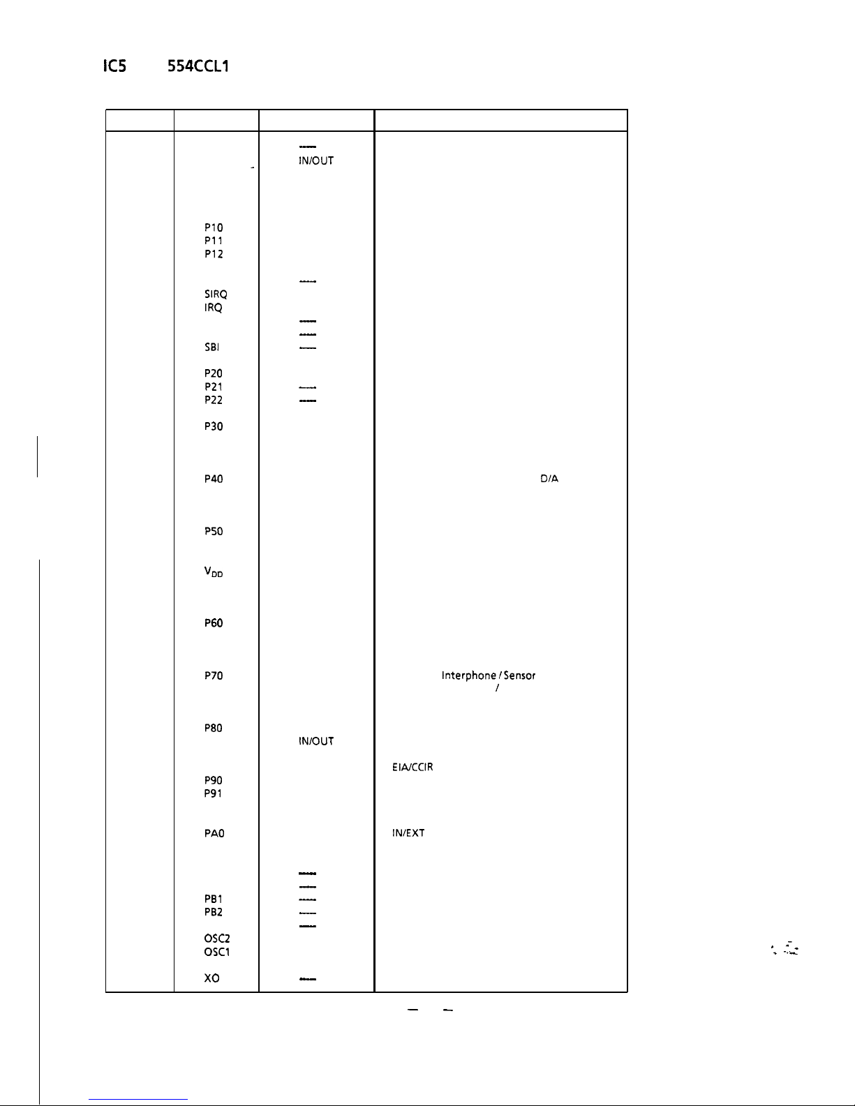
The pin identification and functions of the microprocessor IC6
is described in the table.
4
. --_
*.
I_
-9-
KS
MN1
554CCLl
Pin Identification
Pin No.
Name
1
vss
2
PO0
_
3
PO1
4
PO2
5
PO3
6 PC2
7
PlO
8
Pll
9 P12
10
P13
11
SYNC
12 SIRQ
13
IRQ
14
SBT
15
SBO
16
SBI
17
RST
18 P20
19
P21
20
P22
21
P23
22
P30
23
P31
24
P32
25 P33
26
P40
27
P41
28
P42
29
P43
30
P50
31 P51
32 P52
33
vDD
34
PC0
35
PC1
36
P53
37
P60
38
P61
39
P62
40
P63
41
P70
42
P71
43
P72
44
P73
45
P80
46
P81
47
P82
48
P83
49
P90
50
P91
51
P92
52
P93
53
PA0
54
PA1
55 PA2
56
PA3
57
PBO
58
PBl
59
PB2
60
PB3
61
osc2
62 OSCl
63
XI
64
x0
IN/OUT
-
IN/OUT
IN/OUT
IN/OUT
IN/OUT
OUT
IN/OUT
IN/OUT
IN/OUT
IN/OUT
-
IN
IN
-
-
-
IN
IN/OUT
-
-
IN/OUT
IN/OUT
IN/OUT
IN/OUT
IN/OUT
OUT
OUT
OUT
OUT
OUT
OUT
OUT
IN
OUT
OUT
OUT
IN
IN
IN
IN
IN
IN
IN
IN
IN/OUT
IN/OUT
IN/OUT
IN/OUT
IN/OUT
IN/OUT
IN/OUT
IN/OUT
OUT
OUT
OUT
-
-
-
-
-
OUT
IN
IN
-
Description
Ground
Camera-l Select/LED/Remote Control
Camera-2 Select/LED/Remote Control
Camera-3 Select/LED/Remote Control
Camera-4 Select/LED/Remote Control
Sequence LED Output
Camera-l Power Select/Detection
Camera-2 Power Select/Detection
Camera-3 Power Select/Detection
Camera-4 Power Select/Detection
Not Used
Reset Signal Input
V. Sync Input
Not Used
Not Used
Not Used
Rest In
Adapter Voltage Detection
Not used
Not used
Discharge pulse
Remote control recover
Extension Select 1
Timing
Standby
Key scan output-l Alarm Time
D/A
output
Key scan output-2 Alarm Time D/A output
Key scan output-3 Alarm Time D/A output
Key scan output-4 Alarm Time D/A output
Auto
V sync output
VD output
VDD
Rest output output
Clock output
Ring Counter output
Ring Counter input-2
Ring Counter input-l
Busy control
Recover Input
Camera-4
InterphoneISensor
Input
Camera-3 Interphone / Sensor Input
Camera-2 Interphone /Sensor Input
Camera-l Interphone /Sensor Input
Sequence time
Alarm time control
External Timing Pulse Input
EIAICCIR
select
Key scan -1
Key scan -3
Key scan-2
IN/EXT
Video Select Output
Alarm standby output
Alarm all mode output
Not used
Not used
Not used
Not used
Not used
Clock Pulse Generator
Clock Pulse Generator .
Ground
Not Used
-
10
-
. --_
. .
I_
ADJUSTMENT PROCEDURE
1 TEST EQUIPMENT REQUIRED
The following equipment is required for adjustment of WV-
BM90.
0
Oscilloscope
0
Digital Voltmeter
0
Completely aligned Black and Whrte Camera
WV-EL90
0
Frequency Counter
0
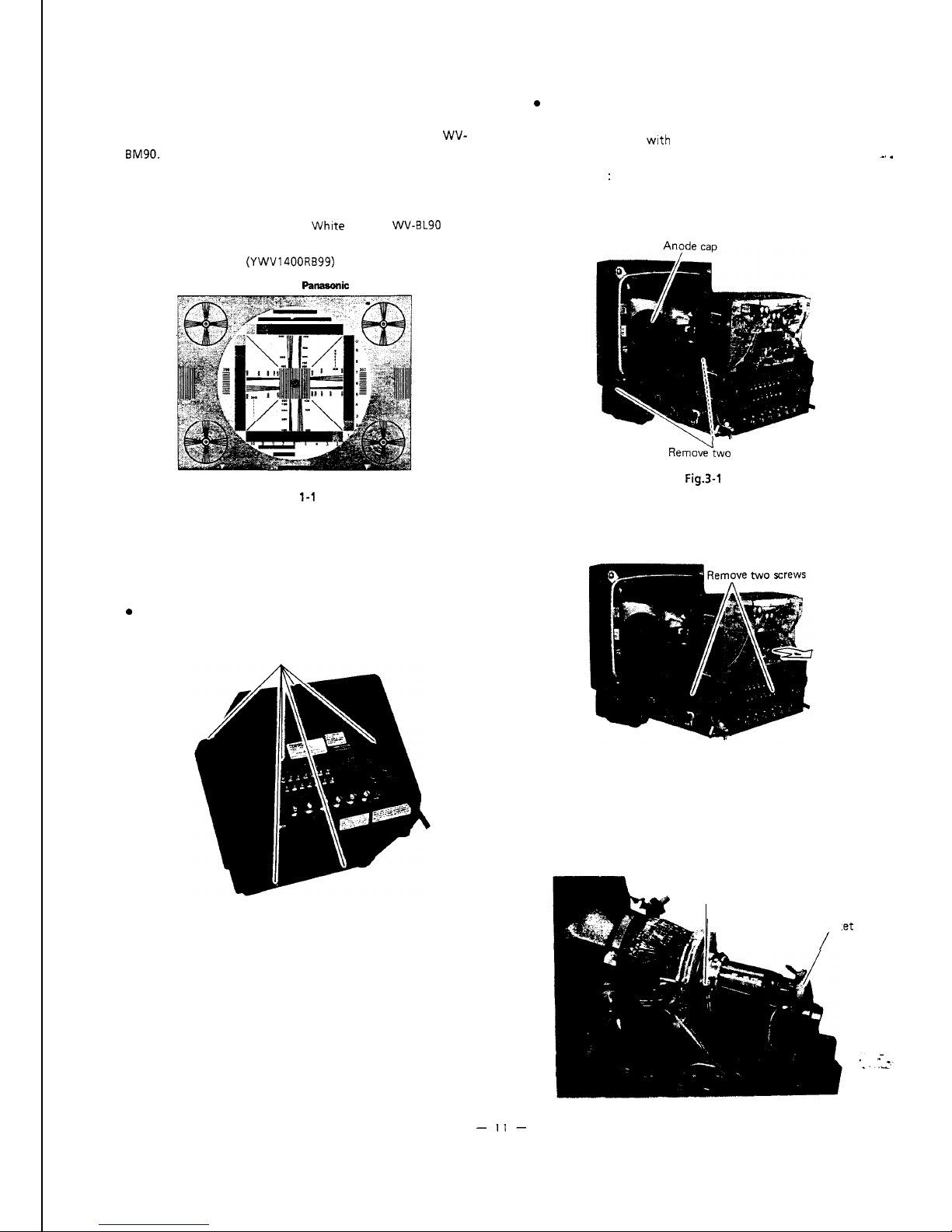
Resolution Chart
(YWV1400RB99)
NATIONAL
FhIEMMIiC
RESOLUTION CHART
Fig.
l-1
3 CRT REPLACEMENT
.
Remove the cover as previously described in section 2.
l
Remove two screws holding the front chassis and slide
back the chassis
wrth
PCB unit.
l
Disconnect the anode cap.
-,
.
Caution
:
Make sure that the anode voltage is
completely discharged by directly connected
between anode terminal and chassis.
RemovG+two
screws
Fig.3-1
.
Remove two screws holding the Control board assembly
and open the direction of the arrow.
2 DISASSEMBLY PROCEDURE FOR
ADJUSTMENT
.
Remove six screws holding the cover and remove the
cover by pulling it backward.
Remove six screws
Fig. 3-2
.
Disconnect the CRT socket by pulling it backward.
.
Loosen the screw holding deflection yoke and
convergence magnets assy and remove the yoke and
magnets assembly by pulling them backward.
Fig. 2-1
Deflection holding screw
CRT Sock
/
.et
Fig. 3-3
.
Remove four screws holding CRT and remove CRT.
Remove four screws
Fig. 3-4
5
(1)
.
.
.
l
(2)
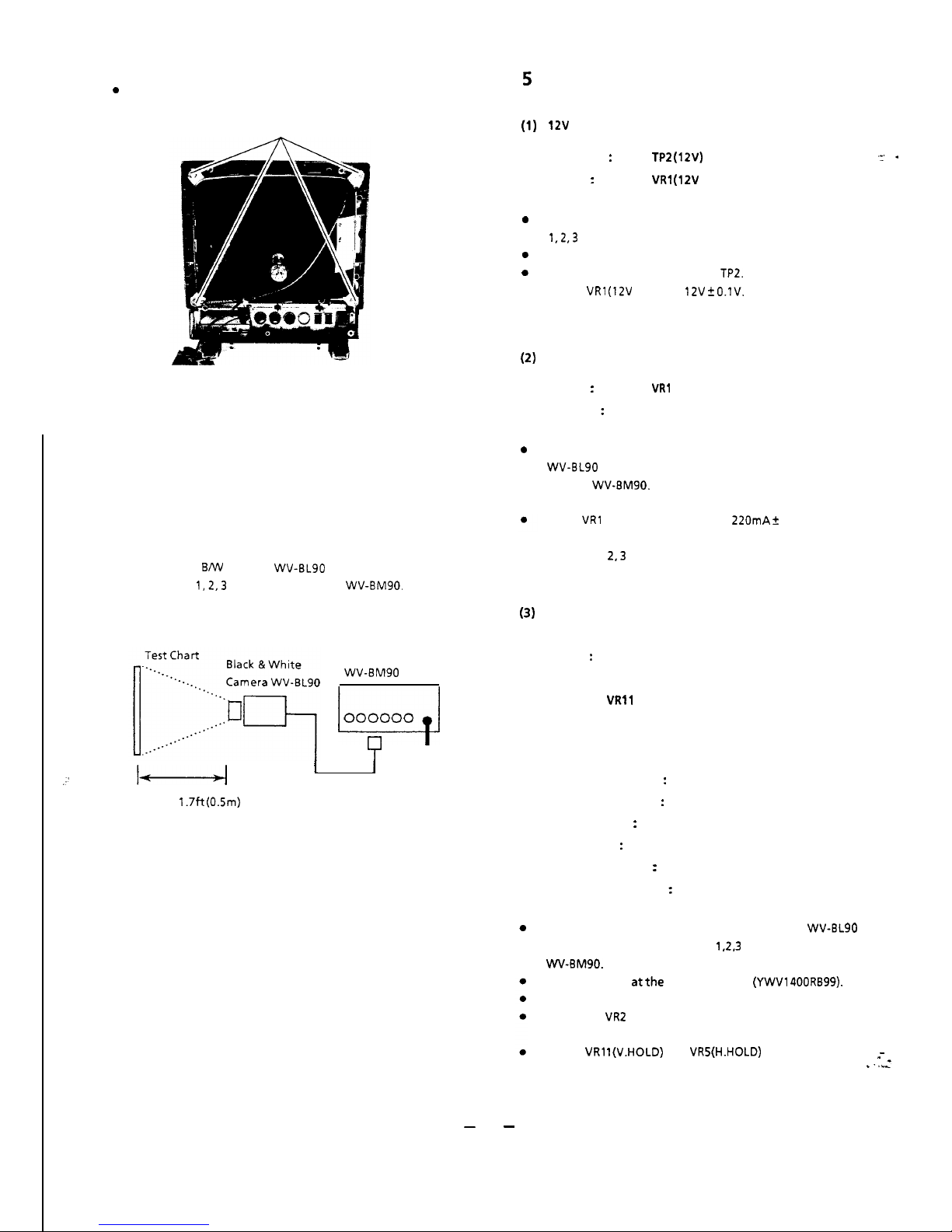
4 CONNECTION AND SETTING UP FOR
ADJUSTMENT
l
l
.
Connect the coaxial cable between the VIDEO OUTPUT
terminal of
BNV
Camera
WV-BL90
and CAMERA INPUT
connector
1,2,3
or 4 of Video Monitor
WV-BM90.
(3)
Video Monitor
WV-EM90
u
000000
7
I
I
:(
Approx.
1.7ft
(0.5m)
l
.
ADJUSTMENT
12V
adjustment
Test
Point
:
TP2 (12V)
Adjust
:
VRl
(12V
ADJ)
Main board
:
*
Main board
Disconnect all cameras from the Camera input connectors
1,2,3
and 4 on the rear panel.
Turn ON the power switch.
Connect the digital voltmeter to
TP2.
Adjust
VRl (12V
ADJ) for
12V 2
O.lV.
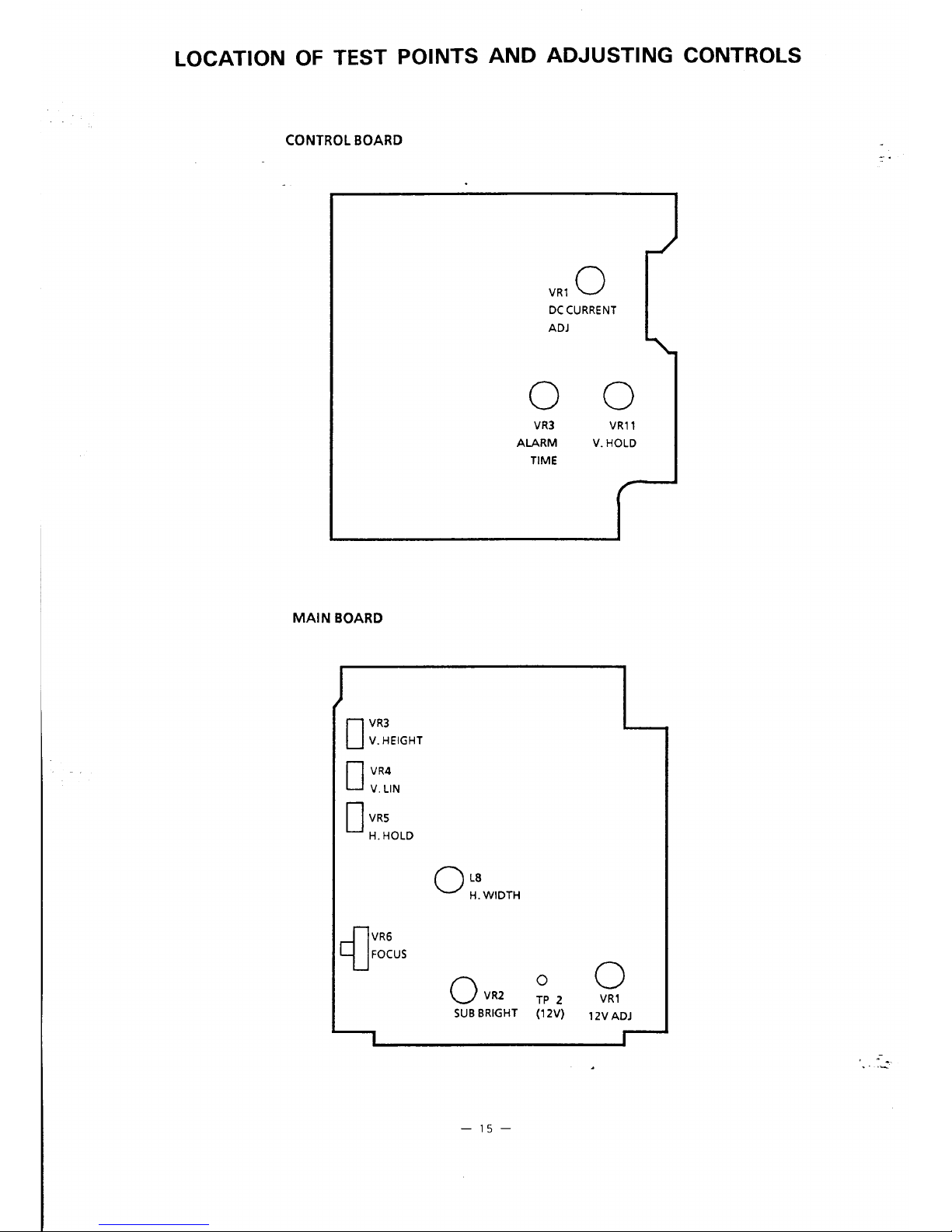
DC current adjustment
Adjust
:
VRl (DC CURRENT)
Observe
:
DC current meter
Control board
Connect the DC current meter between the video camera
WV-BL90
and CAMERA INPUT 1 connector of Video
Monitor
WV-BM90.
Turn ON the power switch.
Adjust
VRl
(DC CURRENTADJ) for
22OmA t
7mA.
Confirm that the DC current of CAMERA INPUT
connectors
2,3
and 4.
H
hold,
V hold coarse adjustment
Adjusts :VR2 (SUB BRIGHT)
Main board
VR5 (H. HOLD)
Main board
VRll
(V. HOLD)
Control board
Set the controls and switches on the volume board and
Control board as follows.
Mode Selection switch
:
Input Selection switch
:
Contrast Control
:
Bright Control
:
Vertical hold control
:
Horizontal hold control
:
ON position
EXT position
Mechanical Center position
Mechanical Center position
Mechanical Center position
Mechanical Center position
Connect the completely aligned video camera
WV-BL90
to CAMERA INPUT connector
1.2.3
or 4 of Video Monitor
WV-BM90.
Aim the camera
atthe
resolution chart
(YWV1400RB99).
Turn ON the power switch.
Adjust the
VR2
(SUB BRIGHT) so that the raster will just
appear.
Adjust VRl l(V.HOLD) and
VR5(H.HOLD)
so that the circle
-
of the resolution chart on the Monitor screen becomes ‘.
Ia
center position.
-
12
-

(4) Picture tilt adjustment
(9) Focus fine adjustment
Adjust
:
Deflection coil
Adjust
:
VR6 (FOCUS)
Main board
0
Loosen the deflection coil holding screw.
0
Adjust VR6 (FOCUS) for best focus in the monitor.
0
Turn the deflection coil until the raster on the monitor
-,
.
screen is straight.
_
0
Carefullytighten the deflection coil holding
screw.
(5) Centering adjustment
Adjust
:
Centering magnets
LE
(H. WIDTH)
Main board
0
Adjust the centering magnets until the raster comes to
the center of monitor screen becomes true circle.
0
Adjust L8 (H. WIDTH) so that the circle of the resolution
chart on the Monitor screen.
(6)
Vertical height and linearity adjustment
Adjust
:
VR4 (V.LIN)
Main board
VR3
(V. HEIGHT)
Main board
0
Adjust VR3 (V. HEIGHT) and V. LIN VR4 so that the
circle
in
the chart is nearly a true circle.
(7) Sub-brightness adjustment
Adjust
:
VR2 (SUB BRIGHT)
Main board
0
Set the controls on the volume board as follows.
Contrast Control
:
Bright Control
:
Fully counter clockwise
Mechanical Center position
0
Turn
VR2 (SU8
BRIGHT) fully clockwise and then turn it
back so that the raster will just go out.
0
Turn VR8 (CONTRAST) at mechanical center position.
(8)
H hold, V hold fine adjustment
Adjust
:
VRS (H.HOLD)
VRll
(V. HOLD)
Main board
Control board
0
Disconnect all cameras from the camera input connector
1,2,3
and 4.
0
Connect the frequency counter to pin 2 (Yellow wire) of
deflection coil and adjust the
VR5
(H HOLD) on the Main
board for 158KHz f 50Hz.
0
Connect the frequency counter to Pin 3 (Red wire) of
deflection coil and adjust the
VRll(V
HOLD) on the
control board for
47.3Hz
2 0.5Hz.
. --_
. .
I_
-
13
-
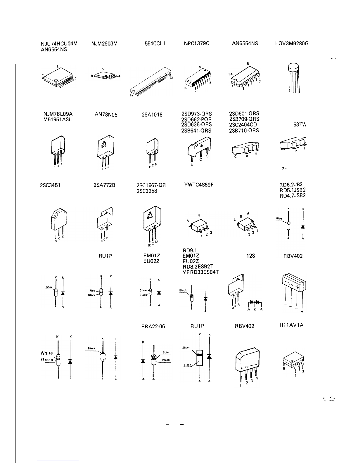
APPEARANCE OF IC, TRANSISTOR AND DIODE
NPC1379C
NJU74HCU04M
AN6554NS
NJM2903M
MN1 554CCLl
AN6554NS LQV3M9280G
2SD973-QRS
2SD601 -QRS
2SD662-PQR
2SB709-QRS
2SD636-QRS
2SC2404CD
2SB641 -QRS
2SB710-QRS
UN2217
MA1 51 K
MA1 53Tw
czm!
c
B
cm
3
2
1 : NC
2 : Anode
3
:
Cathode
XN4501
XN4601
XN4401
RD6.2JB2
RD5.1JSB2
RD4.7JSB2
CTV- 12s
A K A
R
BV402
HllAVlA
NJM78L09A
M51951ASL
AN78N05
2SA1018
P
@
8
C
E
2SC3451
MNCA
2SA772B
2SC1567-OR
2SC2258
YWTC4S69F
RD9.1
ESB3
EMOlZ
EU02Z
RD8.2ESB2T
YFRD33ESB4T
MA1 62TA
MA165
RUlP
EMOlZ
EU02Z
K
K
BllCk
-4’
A
A
ERA22-06
RUlP
K
K
MA185
U06
A
A
. --_
. .
I_
-
14
-
 Loading...