

Page 1
Video Monitor
WV -BM500/WV -BM503
Before attempting to connect or operate this product,
please read these instructions completely.
WV-BM500
WV-BM503
Page 2
This digital apparatus does not exceed the Class A limits for
radio noise emissions from digital apparatus set out in the
Radio Interference Regulations of the Canadian Department
of Communications.
WARNING:
TO PREVENT FIRE OR SHOCK HAZARD, DO NOT EXPOSE THIS APPLIANCE TO RAIN OR MOISTURE.
The lightning flash with arrowhead
symbol, within an equilateral triangle, is
intended to alert the user to the presence of uninsulated "dangerous voltage" within the product's enclosure that
may be of sufficient magnitude to constitute a risk of electric shock to persons.
The exclamation point within an equilateral triangle is intended to alert the
user to the presence of important operating and maintenance (servicing)
instructions in the literature accompanying the appliance.
The serial number of this product may be found on the bottom of the unit.
You should note the serial number of this unit in the space
provided and retain this book as a permanent record of your
purchase to aid identification in the event of theft.
Model No.
Serial No.
Warning:
This equipment generates and uses radio frequency energy
and if not installed and used properly, i.e., in strict accordance with the instruction manual, may cause harmful
interference to radio communications. It has been tested
and found to comply with the limits for a Class A computing
device pursuant to Subpart J of Part 15 of FCC Rules,
which are designed to provide reasonable protection
against such interference when operated in a commercial
environment.
CAUTION:
TO REDUCE THE RISK OF ELECTRIC SHOCK, DO
NOT REMOVE COVER (OR BACK). NO USER SERVICEABLE PARTS INSIDE.
REFER SERVICING TO QUALIFIED SERVICE PERSONNEL.
CAUTION
RISK OF ELECTRIC SHOCK
DO NOT OPEN
SA 1965
SA 1966
For U.S.A
For CANADA
Page 3

-1-
CONTENTS
PREFACE ....................................................................................................................................................................... 2
FEATURES ..................................................................................................................................................................... 2
PRECAUTIONS .............................................................................................................................................................. 2
MAJOR OPERATING CONTROLS AND THEIR FUNCTIONS ........................................................................................ 3
OPERATING PROCEDURE ............................................................................................................................................ 6
INSTALLATION .............................................................................................................................................................. 7
CONNECTIONS ............................................................................................................................................................. 8
SYSTEM CONNECTIONS .............................................................................................................................................. 9
SPECIFICATIONS ......................................................................................................................................................... 10
STANDARD ACCESSORIES ......................................................................................................................................... 11
Page 4

-2-
PREFACE
• The Panasonic WV-BM500 is a desk-top closed
circuit Video Monitor especially designed for surveillance and studio applications.
WV-BM500 features a 5” screen (diagonal actual
visual size) and produces sharp, black-and-white
pictures with horizontal resolution of more than 700
lines at center.
Front mounted controls permit fast picture adjustment. Standard BNC-type input and output connectors enables WV-BM500 to be used with other
CCTV monitors or Panasonic Video Tape
Recorder.
• Model WV-BM503 is a triple monitor combination
with rack-mount chassis that fits the EIA standard
19” rack.
FEATURES
WV-BM500 / WV-BM503
• 5’’ screen (diagonal actual visual size).
• Horizontal resolution 700 lines at center.
• Short H. AFC time constant for VTR playback.
• Bridging input and output connectors for video
and composite sync.
• Available as individual desk top monitor WVBM500, or triple rack mount version WV-BM503.
• DC restoration.
• Internal and External Sync mode.
PRECAUTIONS
• This unit is designed for indoor use. Operable
ambient temperature range must not range
beyond 14°F - 122°F(−10°C - +50°C), and permis-
sible humidity is less than 90%. Avoid using the
monitor under direction sunIight.
• The input power source must be 120V AC 60 Hz .
• Do not block the ventilation slots on the rear panel
and side cover.
• When mounting the Model WV-BM503 in an EIA
standard 19” rack, be careful to insure that the
interior temperature of the rack does not exceed
122°F (+50°C).
Page 5
-3-
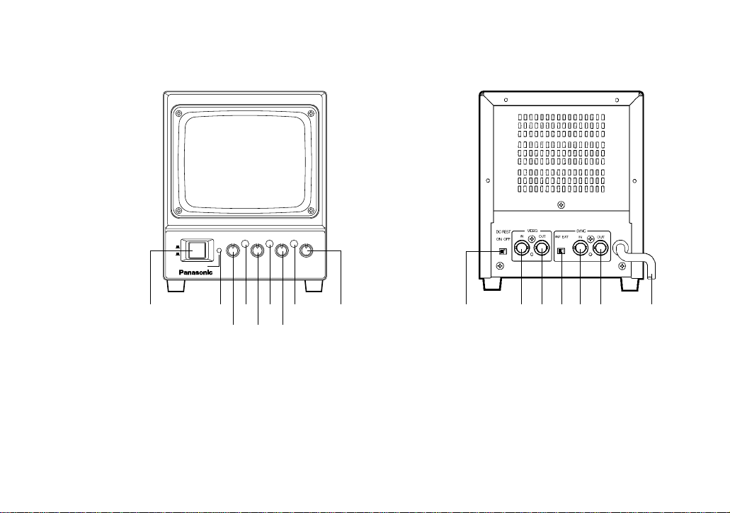
MAJOR OPERATING CONTROLS AND THEIR FUNCTIONS
WV-BM500
<Front View> <Rear View>
1. POWER ON/OFF SWITCH (POWER, ON/OFF)
This is a push-push type switch which turns the
power of this monitor on and off.
Press once and the switch remains down (;) for
turning on the power of monitor.
Press again, the switch comes up (l) for turning
off the power of the monitor.
2. POWER INDICATOR (POWER)
By turning on the Power On/Off Switch (1), this
indicator lights.
H.HOLD
V.LIN
HEIGHT
POWER
ON
OFF
Video Monitor WV-BM
500
V.HOLD BRIGHT
FOCUS
CONTRAST
!1 !2 !3 !4 !5 !6
!0
q
wer
tyu
i
o
Page 6

-4-
3. HORIZONTAL HOLD [H-HOLD]
This control is used to Lock in the picture horizontally.
4. HEIGHT [HEIGHT]
Adjust the vertical height of the picture.
5. VERTICAL HOLD [V-HOLD]
This control is used to Lock in the picture vertically.
6. Vertical Linearity (V-LIN)
Adjust for vertical distortion of the picture.
7. BRIGHTNESS CONTROL [BRIGHT]
Turn this control clockwise to increase the overall
brightness.
8. FOCUS [FOCUS]
Adjust for the clearest picture.
9. CONTRAST CONTROL [CONTRAST]
Turn this control clockwise to increase the picture
contrast .
10. DC RESTORATION SWITCH [DC REST]
Switch to restore background of picture.
11. VIDEO INPUT CONNECTOR (VIDEO IN)
This connector accepts the input video signal
12. VIDEO OUTPUT CONNECTOR (VIDEO OUT)
The video input signal connected to the Video
Input Connector (11) is looped through to this connector and terminated automatically.
13. SYNC SELECTOR SWITCH [SYNC INT/EXT]
14. SYNC INPUT CONNECTOR [SYNC IN]
15. SYNC OUTPUT CONNECTOR [SYNC OUT]
16. AC POWER CORD
Page 7

-5-
WV-BM503
<Front View>
<Rear View>
• Model WV-BM503 combines three WV-BM500 video monitors.
2 31
Video Monitor WV-BM
503
OPEN
@0
@1
!7
!8
!9
Page 8

-6-
17. RACK PANEL (WV-BM503)
18. FIXING SCREW for RACK PANEL (WV-BM503)
19. OPERATION COVER (WV -BM503)
20. PANEL KNOB and SCREW (WV-BM503)
21. RACK-MOUNT CHASSIS (WV-BM503)
OPERATING PROCEDURE
1. Set the Power On/Off Switch (1) to the ON (;)
position.
2. Adjust the Brightness Control (7) and Contrast
Control (9).
3. Adjust the Horizontal Hold
(3) until the picture is stabilized, if the picture slips
to either side, or appears
as a series of horizontal
stripes.
4. Adjust the Vertical Hold
(5), if the picture rolls up
or down.
BRIGHT CONTRAST
H.HOLD
V.HOLD
increaseincrease
Page 9

-7-
5. Height (4)
This recessed screwdriver control should be
adjusted simultaneously to give proper vertical
height consistent with good vertical linearity.
Adjustment should be made to extend the picture
limits approximately 1/10” beyond the top and bottom edges of the mask at over scanning operation.
6. Vertical Linearity (6)
This recessed screwdriver control should be
adjusted to give proper vertical linearity.
7. Focus (8)
The clearest picture is produced when this screwdriver control is adjusted.
8. DC Restoration (10)
DC restoration circuit provides a stable reference
for the black level. Set the switch to ON position to
prevent excessive contrast and preserve shadow
detail.
INSTALLATION
CAUTION:
The following installation should be made by qualified
service personnel or system installers.
Mounting into EIA Standard 19” Rack
Model WV-BM503 can be mounted into EIA 19” rack as
shown below.
WV-BM503
Rack Panel (17)
Rack Mount Chassis (21)
Rack Mount Screws
(Not Supplied)
Fiber Washer
(Part No. YWL1201ER01)
Fixing Screws (18)
(Part No. YWL831-EM01A)
EIA
Rack
Page 10

-8-
CONNECTIONS
Power Cable
1. Keep the camera Power switched OFF during
installation.
2. Connect the Power Cord (16) to a 60 Hz grounded
electrical outlet 120V AC .
Video Cable
1. Use the RG-59/U (3C-2V), RG-6/U (5C-2V). RG11/U (7C-2V) or RG-15/U (10C-2V) coaxial cable.
2. Up to 10 monitors can be hooked up in this configuration before signal loss occurs. Total cable
length should not exceed 500 feet (150m).
3. Wiring Precautions
• Do not bend coaxial cable into a curve whose
radius is smaller than 10 times of its diameter.
• Never crush or pinch the cable
All these will change the impedance of the cable
and cause poor picture quality
Cable RG-59/U RG-6U RG-11/U RG-15/U
(3C-2V) (5C-2V) (7C-2V) (10C-2V)
Recommended (ft) 1650 2475 3300 4125
maximum
cable length (m) 500 750 1000 1250
Recommended maximum cable length
External Sync
When a non-composite video signal is connected to
the monitor, it will be necessary to connect an external
composite sync signal to the monitor.
1. Connect the Sync Input Connector (14) on the
video monitor to the sync signal source by means
of a 75Ω coaxial cable.
2. Set the Sync Selector Switch (13) at EXT position.
NOTE:
1. Non-composite video signal is a signal without
sync.
2. External sync should be composed of mixed H.
Sync and V. sync signals, not H. and V. drive
pulse signals. Composite Sync Level:
4.0 Vp-p (2.0 Vp-p − 5.0 Vp-p)
Page 11

-9-
SYSTEM CONNECTION
1. Single Monitor Connection
2. Multiple Monitor Connection
Internal Sync Connection
• Connect the Video Input Connector (11) on the
monitor to the Video Out Terminal of cameras with
75-ohm coaxial cables.
External Sync Connection
• When a non-composite video signal is connected
to the video monitor, it must also have an external
composite SYNC signal connected to the video
monitor.
• Set the Sync Selector Switch (13) at EXT position.
• Loop through connection of sync signal is the
same as the case of Video Signal.
120V
AC
60 Hz
120V
AC
60 Hz
120V
AC
60 Hz
Last Video Monitor
Camera
Camera
Coax. Cable
WV-BM500
WV-BM500
Coax.
Cable
Coax.
Cable
Page 12

-10-
SPECIFICATIONS
Power Source : 120V AC60Hz
Power Consumption : WV-BM500 Approx. 14W, WV-BM503 Approx. 42W
Tube Size : 5” diagonal actual visual size
Video Input Impedance : 75Ω or high impedance (Auto Termination)
Video Input Level : 1.0 Vp-p composite (0.5 Vp-p - 2.0 Vp-p)
Resolution : More than 700 lines (Horizontal at center)
Scanning Frequency : Horizontal : 15.75k Hz
Vertical : 60Hz
Sweep Linearity : Horizontal : Less than 5%
Vertical : Less than 5%
External Sync Input Impedance : 75Ω or high impedance (Auto Termination)
External Sync Input Level : 4.0 Vp-p negative (2.0 Vp-p - 5.0 Vp-p)
Operating Ambient Temperature : 14°F - 122°F (-10°C - +50°C)
Operating Ambient Humidity : Less than 90 %
Dimensions : WV-BM500: Approx. 5-13/16" (W) x 7-1/16" (H) x 9-5/8” (D)
[147 (W) x 180 (H) x 245 (D) mm]
WV-BM503: Approx. 19’’ (W) x 7”(H) x 10-1/16’’ (D)
[480 (W) x 177 (H) x 256 (D) mm]
Weight : WV-BM500: Approx. 5.1 lbs [2.3 kg]
WV-BM503: Approx. 19.8 lbs [9 kg]
Weight and dimension indicated above are approximate.
Specifications are subject to change without notice.
Page 13

-11-
STANDARD ACCESSORIES (Supplied)
WV-BM503
• Fixing Screws for Rack Panel ...................... 2 pcs.
(Part No. : YWL831-EM01A)
• Fiber Washers ..............................................2 pcs.
(Part No. : YWL1201ER01)
Page 14

N0194-1054 YWV8QA3256BN Printed in Japan
N 7
Broadcast & Television Systems Company
Division of Matsushita Electric Corporation of America
CLOSED CIRCUIT VIDEO EQUIPMENT DIVISION
Executive Office: One Panasonic Way, Secaucus, New Jersey 07094
Regional Offices:
Northeast: 43 Hartz Way, Secaucus, NJ 07094 (201) 348-7303
Southeast: 1854 Shackleford Court, Suite 115, Norcross, CA 30003 (404) 717-6835
Midwest: 1707 North Randall Road, Elgin, IL 60123 (708) 468-5200
Southwest: 4500 Amon Carter Blvd., Ft. Worth, TX 76155 (817) 685-1117
Western: 6550 Katella Ave., Cypress, CA 90630 (714) 373-7265
MATSUSHITA ELECTRIC OF CANADA LIMITED
5770 Ambler Drive, Mississauga, Ontario, L4W 2T3 Canada (905)624-5010
PANASONIC SALES COMPANY
DIVISION OF MATSUSHITA ELECTRIC OF PUERTO RICO, INC.
San Gabriel Industrial Park, 65th Infantry, Ave. KM. 9.5 Carolina, Puerto Rico 00630 (809)750-4300
 Loading...