

Page 1
Operating
In^ructbns
Vìdeo Monitor
WV-BM1900
Panasonic®
Before atieiipi r^g to connoti or thie product
tiicasc road theee foel'uotion» cor'plotoiy
Page 2

A
CAUTION
RISK OF ELECTRIC SHOCK
DO NOT OPEN
A
CAUTION:
TO REDUCE THE RISK OF ELECTRIC SHOCK, DO
NOT REMOVE COVER (OR BACK). NO USER SER
VICEABLE PARTS INSIDE.
REFER SERVICING TO QUALIFIED SERVICE PER
SONNEL
The lightning flash with arrowhead
symbol, within an equilateral triangle, is
intended to alert the user to the pres
ence of uninsulated "dangerous volt
age" within the product's enclosure that
A
SA 1965
WARNING:
TO PREVENT FIRE OR SHOCK HAZARD, DO NOT EXPOSE THIS APPLIANCE TO RAIN OR MOISTURE.
may be of sufficient magnitude to con
stitute a risk of electric shock to per
sons.
The exclamation point within an equi
lateral triangle is intended to alert the
user to the presence of important oper
ating and maintenance (servicing)
instructions in the literature accompa
nying the appliance.
---------------------------------------------------------------------------------ForU.S.A—
Warning:
This equipment generates and uses radio frequency energy
and if not installed and used properly, i.e., in strict accor
dance with the instruction manual, may cause harmful
interference to radio communications. It has been tested
and found to comply with the limits for a Class A computing
device pursuant to Subpart J of Part 15 of FCC Rules,
which are designed to provide reasonable protection
against such interference when operated in a commercial
environment.
The serial number of this product may be found on the.bot
tom of the unit.
You should note the serial number of this unit in the space
provided and retain this book as a permanent record of your
purchase to aid identification in the event of theft.
Model No.
Serial No, _________________________________________
________________________________________
Page 3

CONTENTS
PREFACE ....................................................................................................
FEATURES .................................................................................................
PRECAUTIONS
MAJOR OPERATING CONTROLS AND THEIR FUNCTIONS
CONNECTIONS .........................................................................................
SYSTEM CONNECTIONS ........................................................................
OPERATING PROCEDURE
APPEARANCE ...........................................................................................
SPECIFICATIONS ....................................................................................................................................................................................................12
.........................................................................................
....................................................................
-1-
.... 2
.... 2
.... 2
.... 3
.... 6
.... 7
...10
..
11
Page 4

PREFACE
The Panasonic WV-BM1900 is a desk-top closed cir
cuit Video Monitor especially designed ior surveillance
and studio applications.
This monitor features a 18-5/8" (47cm) diagonal actual
visual size and produces sharp, black-and-white pic
tures with horizontal resolution of more than 850 lines
at centre.
Front mounted controls permit fast picture adjustment.
Standard BNC-type input and output connectors
enables WV-BM1900 to be used with other CCTV moni
tors or Panasonic Video Tape Recorder.
FEATURES
• 18-5/8" (47cm) diagonal actual visual size
• 850 lines of horizontal resolution at centre
• DC restoration On/Off switch is provided.
• Selectable of under or normal scan size
• Short H. AFC time constant for VTR playback.
Looping through BNC connectors for video and
sync input and output
Internal/External Sync mode (switchable)
Rackmount is available with optional rack mount
adaptor
PRECAUTIONS
• This unit is designed for indoor use. Operable
ambient temperature range must not range
beyond 14°F-122T(-10“C -t-50°C), and permissible
humidity is less than 90%. Avoid using the monitor
under direction sunlight.
• The input power source must be 120V AC, 60Hz,
• Do not block the ventilation slots on the rear panel.
• When mounting this monitor in an EIA standard
19" rack, be careful to insure that the interior tem
perature of the rack does not exceed 122°F
(-H50X).
-2-
Page 5
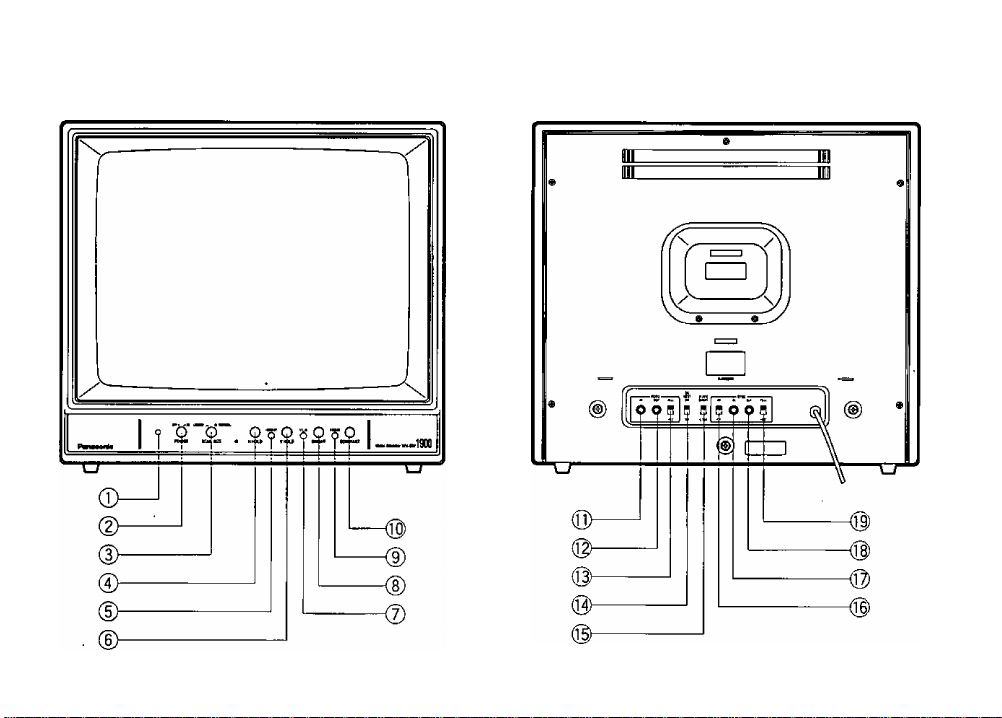
MAJOR OPERATING CONTROLS AND THEIR FUNCTIONS
< FRONT VIEW>
< REAR VIEW >
-3-
Page 6

1. Power Indicator
When turning on the Power On/Off Switch (2), this
indicator lights.
2. Power On/Otf Switch {POWER, ON/OFF)
This switch is used to turn on or off the power of
this monitor.
3. Scan Size Switch (SCAN SiZE UNDER/
NORMAL)
Underscanning is obtained by pressing this
switch.
8. Bright Control [BRIGHT]
Turn this control clockwise to increase the overall
brightness,
9. Focus Control [FOCUS]
Adjust for the clearest picture.
10. Contrast Control [CONTRAST]
Turn this control clockwise to increase the picture
contrast.
4. Horizontal Hold Control [H-HOLD]
This control is used to lock in the picture horizon
tally.
5. Height Control [HEIGHT]
Adjust the vertical height of the picture,
6. Vertical Hold Control [V-HOLD]
This control is used to lock in ttie picture vertically.
7. Vertical Linearity Control (V-LIN)
Adjust for vertical distortion of the picture.
11. Video Input Connector (VIDEO IN)
This connector accepts the input video signal.
12. Video Output Connector (VIDEO OUT)
The video input signal connected to the Video
Input Connector (11) is looped through to this con
nector.
13. Video Termination Switch (VIDEO 7512/HiZ)
When bridging or looping through the video signal,
set this switch to Hi-Z position, and for other cases
this switch should be set to 750 position.
-4-
Page 7

14. DC Restoration Switch (DC REST ON/OFF)
Switch to restore background of picture.
15. H.AFC Switch (H.AFC SHORT/LONG)
Set this switch to the SHORT position {short H.
AFC time constant) for VTR playback.
16. Sync Selection Switch (SYNC iNT/EXT)
17. Sync Input Connector (SYNC IN) (BNC)
18. Sync Output Connector (SYNC OUT) (BNC)
19. Sync Termination Switch (SYNC 75Q/Hi-Z)
When bridging or looping through the external
sync signal, set this switch to the Hi-Z position,
and for other cases this switch should be set to the
75Q position.
-5-
Page 8

CONNECTIONS
Power Cable
1. Keep the power of this monitor to the OFF position
during connection.
2. Connect the Power Cord to a 60F!z grounded elec
trical outlet 120V AC.
Video Cable
Note:
• Always set the last monitor’s Video Termination
Switch to 75 ii, and set the Video Termination
Switch of Intermediate monitors to Fii-Z.
Camera Coax.
Use the RG-59/U (3C-2V), RG-6/U (5C-2V), RG-
11/U (7C-2V) or RG-15/U (10C-2V) coaxial cable.
Up to 10 monitors can be hooked up in this config
uration before signal loss occurs. Total cable
length should not exceed 150m (500 feet)
Cable
Monitor Monitor
.VIDEO
.....
Coax.
Cable
© @ 0
© ® В
2. Wiring Precautions :
• Do not bend coaxial cable into a curve whose
radius is smaller than 10 times its diameter.
• Never staple the cable - not even with circular sta
ples,
• Never crush or pinch the cable.
All these will change the impedance of the cable
and cause poor picture quality.
External Sync
When a non-composite video signal is connected to
the monitor, it will be necessary to connect an external
composite sync signal to the monitor.
1. Connect the Sync Input Connector (17) on the
video monitor to the sync signal source by means
of a 75 Q coaxial cable.
Set the Sync Selector Switch (16) to the EXT posi
tion.
SYNC
INT
У
3. The operation of Sync Termination Switch (19) is
the same as Video Termination Switch (13).
-6-
Page 9

SYSTEM CONNECTIONS
2. Muitipie Monitor Connection
1. Single Monitor Connection
• Connect the Video Input Connector (11) on this
monitor to the Video Output Connector of the cam
era with 75-ohm coaxial cable.
• Set the Video Termination Switch (13) to the
75ii position.
• Set the Sync Selector Switch (16) to the I NT posi
tion.
First Video Monitor
Conneci the Video Input Connector (11) on this
monitor to the Video Output Connector of the cam
era with 75-ohm coaxial cable.
-7-
Page 10

Connect the Video Output Connector (12) on the
first monitor to the Video Input Connector (11) on
the second monitor with 75-ohm coaxial cable.
Continue until all monitors are connected.
Set the Video Termination Switch (13) of the first
and intermediate monitors at Hi-Z position. Then
set the Video Termination Switch (13) of the last
monitor to 75ii position.
3. When used with External Sync
When a non-composite video signal is connected
to the video monitor, an external composite SYNC
signal must also be connected to the video moni
tor.
• Connect the Video Input Connector (11) on the
video monitor to the Video Output Connector of the
camera with 75-ohm coaxial cable.
• Connect the Video Output Connector (12) on the
first monitor to the Video Input Connector (11) on
the second monitor with 75-ohm coaxial cable.
Continue until the video signal is connected to all
monitors.
• Set the Video Termination Switch (13) of the first
and intermediate monitors to the Hi-Z position.
These set the Video Termination Switch (13) of the
last monitor to the 750. position.
-8-
Page 11

Set the Sync Selector Switch (16) to the EXT posi
tion.
Connect the Sync Input Connector (17) on the
video monitor to the sync signal source with' 75ohm coaxial cable.
Connect the Sync Output Connector (18) on the
first monitor to the Sync Input Connector (17) on
the second monitor with 75-ohm coaxial cable.
Continue until the sync signal is connected to all
monitors.
Connect the Sync Output Connector (18) on the
last monitor to the Sync Input Connector on the
camera with 75-ohm coaxial cable.
Set the Sync Termination Switch (19) of the moni
tors to Hi-Z position. The sync signal is terminated
with 75-ohm in the camera.
-9-
Page 12

OPERATING PROCEDURE
1. Set the Power On/Off Switch (2) to the ON position.
OFF*^ ioN
POWER
2. Adjust the Bright Control (8) and Contrast Control
(10).
BRIGHT CONTRAST
Adjust the Horizontal Hold Control (4) until the pic
ture is stabilized, if the picture slips to either side,
or appears as a series of horizontal strips.
4.
Adjust the Vertical Hold Control (6), if the picture
rolls up or down.
H-HOLD
V-HOLD
-10-
Height Control
This recessed screwdriver control should be
adjusted simultaneously to give proper vertical
height consistent with good vertical linearity.
Adjustment should be made to extend the picture
limits approximately 1/10" beyond the top and bot
tom edges of the mask at over scanning operation.
Vertical Linearity Control
This recessed screwdriver control should be
adjusted to give good vertical linearity.
Underscanning Operation
7.
Set the Scan Size Switch (3) to the UNDER posi
tion to obtain the underscanning.
UNDER
DC Restoration
DC restoration circuit provides a stable reference
for the black level. Set the switch to the ON posi
tion to prevent excessive contrast and preserve
shadow detail.
M. NORMAL
SCAN SIZE
Page 13

APPEARANCE
Unit: inchies (mm)
-11-
Page 14

SPECIFICATIONS
Power Source ;
Power Consumption :
Video Input :
External Sync Input:
Horizontal Resolution :
Maximum Video Gain :
H. AFC Time Constant :
Sweep Linearity ;
Sweep Geometry :
Overscanning :
Scanning ;
DC Restoration :
CRT Size :
Actual Visual Size :
High Voltage :
Ambient Operating temperature
Ambient Operating Humidity :
Dimensions :
Weight :
Weight and dimension indicated above are approximate.
Specifications are subject to change without notice.
120VACat60Hz .
Approx. 70 watts
0.5 - 2.0 Vp-p composite/75iior Hi-Z looping through
0.2 - 1.7 Vp-p non-composite/75iior Hi-Z looping through
2.0 - 5.0 Vp-p composite/75iior Hi-Z looping through
More than 850 lines at centre
42 dB
Short time constant for industrial VTRs
Less than 10% at overscan
Less than 2% at overscan
Approx. 5%
Overscan or underscan switchable
Yes
19-7/8” {50cm} diagonal
18- 5/8" (47cm) diagonal
DC 18kV
14T-122T(-10“C--t-50°C)
Less than 90%
19- 3/16"(W) X 17-3/4"(H) X 14-7/8"(D) (483(W) x 450.5(H) x 378(D)mm)
40.7 lbs. (18.5 kg)
-12-
Page 15

Page 16

Panasonic
Broadcast & Television Systems Company
Division of Matsushita Electric Corporation of America
CLOSED CIRCUIT VIDEO EQUIPMENT DIVISION
Executive Office: One Panasonic Way. Secaucus, New Jersey 07094
Regional Offices:
Northeast: 43 Hartz Way, Secaucus, NJ 07094 (201) 348-7303
Southeast: 1654 Shackleford Court, Suite 115, Norcross, GA 30003 (404) 717-6835
Midwest: 1707 North Randall Road, Elgin, IL 60123 (708) 468-5200
Southwest: 4500 Amon Carter Blvd., Ft. Worth, 1X76155(817) 685-1117
Western: 6550 Katella Ave., Cypress. CA 90630 (714) 373-7265
MATSUSHITA ELECTRIC OF CANADA LIMITED
5770 Ambler Drive, Mississauga, Ontario, L4W 2T3 Canada (905)624-5010
PANASONIC SALES COMPANY
DIVISION OF MATSUSHITA ELECTRIC OF PUERTO RICO, INC.
San Gabriel Industrial Park, 65th Infantry, Ave. KM, 9,5 Carolina, Puerto Rico 00630 (809)750-4300
___________
N0594-0 YWV8QA3344AN
Printed in Japan
® 13
 Loading...