

Page 1
Color CCTV Camera
WV-CF202
CCTV Camera
WV-BF102
Before attempting to connect or operate this product,
please read these instructions completely.
FRANÇAIS ENGLISH
Page 2
WARNING:
TO PREVENT FIRE OR ELECTRIC SHOCK HAZARD, DO NOT EXPOSE THIS APPLIANCE TO RAIN OR MOISTURE.
The lightning flash with arrowhead
symbol, within an equilateral triangle,
is intended to alert the user to the
presence of uninsulated "dangerous
voltage" within the product's enclosure that may be of sufficient magnitude to constitute a risk of electric
shock to persons.
The exclamation point within an equilateral triangle is intended to alert the
user to the presence of important
operating and maintenance (servicing) instructions in the literature
accompanying the appliance.
The serial number of this product may be found on the top
of the unit.
You should note the serial number of this unit in the space
provided and retain this book as a permanent record of your
purchase to aid identification in the event of theft.
Model No.
Serial No.
Warning:
This equipment generates and uses radio frequency energy
and if not installed and used properly, i.e., in strict accordance with the instruction manual, may cause harmful
interference to radio communications. It has been tested
and found to comply with the limits for a Class A computing
device pursuant to Subpart J of Part 15 of FCC Rules,
which are designed to provide reasonable protection
against such interference when operated in a commercial
environment.
CAUTION:
TO REDUCE THE RISK OF ELECTRIC SHOCK, DO
NOT REMOVE COVER (OR BACK). NO USER SERVICEABLE PARTS INSIDE.
REFER SERVICING TO QUALIFIED SERVICE PERSONNEL.
CAUTION
RISK OF ELECTRIC SHOCK
DO NOT OPEN
SA 1965
SA 1966
For U.S.A
Page 3

-1-
CONTENTS
PREFACE ........................................................................................................................................................................ 2
FEATURES ...................................................................................................................................................................... 2
PRECAUTIONS ............................................................................................................................................................... 3
MAJOR OPERATING CONTROLS AND THEIR FUNCTIONS ......................................................................................... 4
CONNECTION ................................................................................................................................................................ 6
INSTALLATION ............................................................................................................................................................... 8
ADJUSTMENT ............................................................................................................................................................... 14
PREVENTION OF BLOOMING AND SMEAR ............................................................................................................... 17
SPECIFICATIONS ......................................................................................................................................................... 18
STANDARD ACCESSORIES ......................................................................................................................................... 20
OPTIONAL ACCESSORIES .......................................................................................................................................... 20
ENGLISH
Page 4

-2-
PREF ACE
Panasonic’s WV-CF202/WV-BF102 CCTV camera is
designed for advanced video surveillance with a new
concept, mini-dome shape, and introduces a new level
of the high picture quality and high resolution through
the use of a 1/4-inch interline transfer CCD image sen-
WV-CF202
• Signal-to-noise ratio of 46 dB
• Maximum illumination of 10 lux (1 foot-candle)
• Horizontal resolution of 330 lines
WV-BF102
• Signal-to-noise ratio of 46 dB
• Maximum illumination of 0.5 lux (0.05 foot-candle)
• Horizontal resolution of 370 lines
FEA TURES
sor having 512 horizontal pixels (picture elements) and
one chip signal processor. Additionally, optional lenses
with various angular of view are available to meet your
needs.
Page 5

-3-
5. Never face the camera towards the sun.
Do not aim the camera at bright objects. Whether
the camera is in use or not, never aim it at the sun
or other extremely bright objects. Otherwise,
blooming or smear may be caused.
6. Do not use chemical e.g. thinner or benzene for
cleaning the lens.
When the lens becomes dirty, wipe it using a soft
cloth or a cloth soaked with alcohol. Using chemical e.g. thinner or benzene for cleaning the lens
may damage the surface of the lens.
7. Do not operate the camera beyond the specified
temperature, humidity or power source ratings.
Use the camera under conditions where temperature is between −10°C - +50°C (14°F - 122°F), and
humidity is below 90%. The input power source is
12V DC.
Caution:
To prevent fire or electric shock hazard, a UL
listed wire (VW-1, style 1007) should be used for
12V DC Input Terminals.
PRECAUTIONS
1. Do not attempt to disassemble the camera.
To prevent electric shock, do not remove screws
or covers.
There are no user serviceable parts inside. Ask a
qualified service person for servicing.
2. Handle the camera with care.
Do not abuse the camera. Avoid striking, shaking,
etc. The camera could be damaged by improper
handling or storage.
3. Do not expose the camera to rain or moisture,
or try to operate it in wet areas.
This model is produced for indoor use. If the camera is exposed to rain or moisture, turn the power
off immediately and ask a qualified service person
for servicing. Moisture can damage the camera
and also create the danger of electric shock.
4. Do not use strong or abrasive detergents when
cleaning the camera body.
Use a dry cloth to clean the camera when dirty.
In case the dirt is hard to remove, use a mild
detergent and wipe gently.
Page 6
-4-
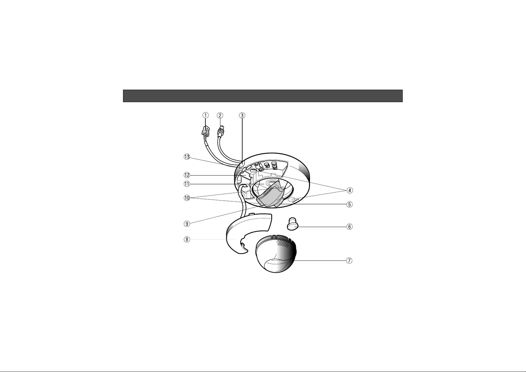
MAJOR OPERATING CONTROLS AND THEIR FUNCTIONS
Page 7

-5-
q DC Power Input Connector
This connector is for connecting the 12V DC power
supply cable.
w Video Output Connector
This connector is for connecting with the VIDEO IN
connector of the monitor.
e Cable Exit
Pass the cables through this concave when
installing on the ceiling/wall.
r Camera Mounting Screw Holes
Mount the camera by fixing with screws through
these holes.
t Lens
Rotate this lens to adjust the focus.
y Rubber Cap (standard accessory)
Attach this cap on the camera mounting screw
hole.
u Dome Cover
This protects the camera head.
i Panel Cover
Open this cover when installing the camera or connecting the cables.
o Camera Head
This adjusts the tilting angle of the camera.
!0 Lens Holder
These holders bring the picture in an upright position on the monitor screen.
!1 Panning Table
This adjusts the panning angle of the camera.
!2 Cable Hole
Pass the cables through this hole when installing
on the ceiling/wall.
!3 Panel Cover Detaching Slit
Insert a tool, such as a screwdriver (−), into this slit
to open the panel cover.
Cautions:
• Connect to 12 V DC (10.5 V-16 V) class 2
power supply only. Make sure to connect the
grounding lead to the GND terminal when
the power is supplied from a 12 V DC power
source.
• To prevent fire or electric shock hazard, use
a UL listed wire VW-1, style 1007 cable for
the Input Terminal.
Page 8

-6-
CONNECTION
Precaution:
The following connections should be made by qualified service personnel or system installers.
To Video IN
(CAMERA IN)
Video Output Cable
12V DC
BNC Plug
BNC
Plug
Coaxial Cable
Page 9

Pin No.
Copper wire size
(AWG)
#18
(0.83mm
2
)
-7-
How to assemble the cable with the accessory
connector
Strip back the cable jacket approx. 3 mm (1/8 inch)
and separate the individual conductors.
Recommended wire gauge sizes for 12 V DC line.
#24
(0.22mm
2
)
Length
of Cable
(Approx.)
(m)
(ft)
#22
(0.33mm
2
)
#20
(0.52mm2)
20 30 45 75
65 100 160 260
Accessory Connector Information
Power Source Cable Color
1 :
2 :
Ground
DC 12V
Black
White
Prepare the individual conductors for clamping. Use
MOLEX band tool part number 57027-5000 (for ULStyle Cable UL1015) or 57026-5000 (for UL-Style
UL1007) for clamping the contacts.
After clamping the contacts, push them into the proper
holes in the accessory connector of this camera until
they snap in place.
• Shrinking the cable-entry seal is a one-time procedure. Do not shrink the cable-entry seal until it
has been ascertained that the unit is functioning.
CONNECT THIS TO 12V DC CLASS 2 POWER
SUPPLY ONLY.
• To prevent fire or electric shock hazard, the UL
listed wire VW-1 style 1007 should be used for
the cable for 12V DC Input Terminals.
Up
Wire
Contact
Up
Contact
Wire
Approx.
3 mm (1/8 inch)
Insert the wire until A position
and clamp the contacts.
2
1
• Power supply connection
Cautions
Insert
A
Page 10

-8-
INST ALLATION
Important Notices:
• The following installation should be made by qualified service personnel or system installers and
should confirm to all local codes.
• Be sure to use a ceiling board having enough
strength to support this camera.
Mounting the camera when you can make a hole for
the cables on the ceiling/wall.
When you can make a hole for the cables on the ceiling/wall where the camera to be installed, proceed as
follows;
1. Make a hole on the ceiling/wall after checking the
place the camera to be installed with making reference to the diagram right.
83.5mm
10mm
9.5mm
19mm
15mm
Front/Upper
Page 11

-9-
2. Open the panel cover by using a tool, such as a
screwdriver (−).
3. Pass the cables through the cable hole.
Page 12

-10-
4. Connect the cables as described in the previous
section “CONNECTION”.
6. Mount the camera onto the ceiling/wall by fixing
with the mounting screws.
Note: Before fixing with the screws, confirm the
direction of the camera by checking the position of the logo “Panasonic” on the camera
cover.
“Panasonic” logo indicates the front (when
installed on the ceiling)/upper (when installed
on the wall) direction of the camera.
5. Remove the rubber
cap from the camera
mounting screw hole
on the camera cover.
Page 13

-11-
Front/Upper
7. Close the panel cover. Make sure the panel cover
is closed properly and firmly.
8. Attach the rubber cap into the camera mounting
screw hole on the camera cover.
Page 14

-12-
Mounting the camera when you can not make a hole
for the cables on the ceiling/wall.
When you can not make a hole for the cables on the
ceiling/wall where the camera to be installed, proceed
as follows;
1. When you can not make a hole in the ceiling/wall to
pass the cables through, cut and remove the plastic part to make the concave for cables.
2. Open the panel cover by using a tool, such as a
screwdriver (−).
3. Detach the video output connector cable and the
DC power input connector cable from the camera.
4. Pass the cables through the concave, and attach
the cables to the camera again.
Page 15

-13-
5. Connect the cables as described in the previous
section “CONNECTION”.
6. Remove the rubber cap form the camera mounting
screw hole on the camera cover.
7. Mount the camera onto the ceiling/wall by fixing
with the mounting screws.
Note: Before fixing with the screws, confirm the
direction of the camera by checking the position of the logo “Panasonic” on the camera
cover.
“Panasonic” logo indicates the front (when
installed on the ceiling)/upper
(when installed on the wall) direction of the
camera.
8. Close the panel cover. Make sure the panel cover
is closed properly and firmly.
9. Attach the rubber cap into the camera mounting
screw hole on the camera cover.
Page 16

-14-
ADJUSTMENT
1. Panning
1. Remove the dome cover from the camera.
Hold here
2. Adjust the direction of the camera head by moving
the panning table. To move the panning table, hold
the camera head holder and move it. The panning
table can be moved ±90° (180°).
Camera Head
Camera Head
Holder
90
K
90
K
Page 17

-15-
2. Tilting the camera
The tilting angle is shown below.
The camera head can be tilted ±75° (150°).
46
Vertical Angular
of View
Vertical Angular
of View
(max.)
75
46
Notes:
• Uprighting the picture on the monitor screen is usually necessary. (Refer to 3. Uprighting the picture.)
• The shadow of the dome cover will be taken by the
camera when the camera head is tilted close to the
camera cover. When an optional lens is installed on
the camera, see the operational instruction of the
lens and check the angular field of view.
3. Uprighting the picture
Bring the picture on the monitor screen in an
upright position by turning the camera head. To
turn the camera head, hold the camera head and
turn it. The camera head can be turned ±90°
(180°).
Page 18

-16-
4. Focusing
Adjust the focus by turning the lens.
After adjusting the focus, attach the dome cover to
the camera body.
Dome Cover
Page 19

-17-
When the camera is aimed at a bright light, such as a
spotlight, or a surface that reflects bright light, smear
or blooming may appear. Therefore, the camera
should be operated carefully in the vicinity of extremely
bright objects to avoid smear or blooming.
Bright object
Smear
PREVENTION OF BLOOMING AND SMEAR
Page 20

-18-
WV-CF202
Pick-up Device: 512 (H) x 492 (V) pixels, Interline Transfer CCD
Scanning Area: 3.16 (H) x 2.72 (V) mm (Equivalent to scanning area of 1/4” pick-up tube)
Scanning: 525 lines / 60 fields / 30 frames
Horizontal: 15.734 kHz
Vertical: 59.94 Hz
Synchronization: Internal
Video Output: 1.0 V[p-p] NTSC composite 75 Ω / BNC connector
Horizontal Resolution: 330 lines
Signal-to-Noise Ratio: 46 dB (AGC OFF, weight ON)
Minimum Illumination: 10 lx (1 foot-candle) at WIDE end
Angular Field of View: Horizontal; 62°
Vertical; 46°
Electronic Light Control: Equivalent to continuous variable shutter speed between 1/60 s and 1/10 000 s
White Balance: ATW
Ambient Operating Temperature: −10°C - +50°C (14°F - 122°F)
Ambient Operating Humidity: Less than 90%
Power Source: 12V DC, 110mA
Dimensions: 64 (H) x 130 (D) mm [2-1/2” (H) x 5-1/8” (D)]
Weights: 0.3 kg (0.7 lbs.)
Weights and dimensions indicated are approximate.
Specifications are subject to change without notice.
SPECIFICA TIONS
Page 21

-19-
WV-BF102
Pick-up Device: 512 (H) x 492 (V) pixels, Interline Transfer CCD
Scanning Area: 3.16 (H) x 2.72 (V) mm (Equivalent to scanning area of 1/4” pick-up tube)
Scanning: 525 lines / 60 fields / 30 frames
Horizontal: 15.734 kHz
Vertical: 59.94 Hz
Synchronization: Internal
Video Output: 1.0 V[p-p] EIA composite 75 Ω / BNC connector
Horizontal Resolution: 370 lines
Signal-to-Noise Ratio: 46 dB (AGC OFF)
Minimum Illumination: 0.5 lx (0.05 foot-candle) at WIDE end
Angular Field of View: Horizontal; 62°
Vertical; 46°
Electronic Light Control: Equivalent to continuous variable shutter speed between 1/60 s and 1/10 000 s
Ambient Operating Temperature: −10°C - +50°C (14°F - 122°F)
Ambient Operating Humidity: Less than 90%
Power Source: 12V DC, 80mA
Dimensions: 64 (H) x 130 (D) mm [2-1/2” (H) x 5-1/8” (D)]
Weights: 0.3 kg (0.7 lbs.)
Weights and dimensions indicated are approximate.
Specifications are subject to change without notice.
Page 22

-20-
ST ANDARD ACCESSORIES
Rubber Cap................................................................................1
Connector for Power...................................................................1
OPTIONAL ACCESSORIES
Lenses.....................WV-LXY18C4, WV-LXY23C4, WV-LXY47C4
Page 23

N0498-1058 YWV8QA4963BN Printed in Japan
N 30
Video Imaging Systems Company
A Division of Panasonic Broadcast & Television Systems Company
A Unit of Matsushita Electric Corporation of America
Executive Office: One Panasonic Way 4H-2, Secaucus, New Jersey 07094
Regional Offices:
Northeast: One Panasonic Way, Secaucus, NJ 07094 (201) 348-7303
Southeast: 1225 Northbrook Parkway, Suite 1-160, Suwanee, GA 30024 (770) 338-6838
Midwest: 1707 North Randall Road, Elgin, IL 60123 (847) 468-5211
Southwest: 8105 Beltsline Road, Suite 100, Irving, TX 75063 (927) 915-1334
Western: 6550 Katella Ave., Cypress, CA 90630 (714) 373-7840
PANASONIC CANADA INC.
5770 Ambler Drive, Mississauga, Ontario, L4W 2T3 Canada (905)624-5010
PANASONIC SALES COMPANY
DIVISION OF MATSUSHITA ELECTRIC OF PUERTO RICO, INC.
San Gabriel Industrial Park, 65th Infantry Ave. KM. 9.5 Carolina, P.R. 00630 (809)750-4300
 Loading...