

Page 1

Setup Instructions
PC Software Package
Model No. WV-ASM200
WV-ASM200W
Extension Software
Model No. WV-ASE201, WV-ASE202
WV-ASE203, WV-ASE204
WV-ASE231
WV-ASE201W, WV-ASE202W
WV-ASE203W, WV-ASE204W
Before attempting to connect or operate this product,
please read these instructions carefully and save this manual for future use.
The model number is abbreviated in some descriptions in this manual.
Page 2

2
3
CONTENTS
Preface .......................................................................3
Software configuration ........................................... 3
System configuration .............................................3
System specifications ............................................ 4
Compatible devices ................................................ 5
About the setup software .......................................6
Standard accessories ............................................. 7
About the user manuals ......................................... 8
System requirements ............................................. 8
Recommended camera settings when monitoring
MPEG-4 or H.264 images .................................... 10
Trademarks and registered trademarks ............... 10
Abbreviations .......................................................10
Document convention .......................................... 11
Operation flow .......................................................... 13
Installation/uninstallation ..........................................14
Installation ............................................................ 14
Uninstallation ........................................................ 15
Start/exit the setup software .................................... 16
Setup window ........................................................... 18
Settings relating to the system ................................. 19
Select the operating language, date format,
time format, etc. [Basic setup] ............................. 19
Set the maximum refresh interval
[Performance] .......................................................22
Settings relating to the device management ............ 23
Register a recorder [Basic setup] .........................23
Edit the registered recorder information
[Basic setup] ......................................................... 31
Delete the registered recorder [Basic setup] ........31
Register an encoder [Basic setup] ....................... 32
Edit the registered encoder information
[Basic setup] ......................................................... 37
Delete the registered encoder [Basic setup] ........ 38
Register a camera [Basic setup] ..........................39
Edit the registered camera information
[Basic setup] ......................................................... 46
Delete the registered camera [Basic setup] ......... 47
Register a decoder [Basic setup] ......................... 48
Edit the registered decoder information
[Basic setup] ......................................................... 51
Delete the registered decoder [Basic setup] ........52
Settings relating to the user management ............... 53
User authentication, auto login user, password's
validation period setting [Basic setup] ................. 53
Settings relating to the administrator
[Administrator setup] ............................................ 54
Apply the user level for each user
[User level setup] ..................................................55
Functions that can be restricted ..........................56
Manage the registered users [User setup] ........... 57
Settings relating to the cameras...............................62
Register a group [Group] ...................................... 62
Register a sequence [Sequence] ......................... 65
Settings relating to the window ................................ 69
Use the live window [Live window] ......................69
Use the map window [Map window] .................... 70
Settings relating to the face search .......................... 74
Add a face search server .....................................74
Correct the face search server .............................77
Delete the face search server ............................... 78
Configure the behavior setting of the
face search server ................................................79
Settings relating to the event action ......................... 80
Settings for the event action upon an alarm
occurrence [Alarm] ............................................... 80
Settings for the event action upon an error
occurrence [Error] ................................................. 82
Settings relating to the communication....................83
Network settings [Basic setup] ............................ 83
Settings relating to the alarm notification from the
device using Panasonic alarm protocol
[Panasonic Alarm] ................................................ 84
Settings relating to the controller ............................. 85
Camera number setting [Camera number] ........... 85
Group number setting [Group number] ................88
Sequence number setting [Sequence number] .... 91
Settings relating to the maintenance ........................ 94
Display the version of this software
[Version information] ............................................. 94
Display/save the application log
[Application log] .................................................... 94
Display/save the recorder log [Recorder log] ..... 101
Delete the operation log automatically
[Auto delete] ....................................................... 104
Save/load/initialize the setup data or logs
[Save/Load] ........................................................ 105
Settings relating to the license registration ............ 109
Register the license ............................................ 109
Exceptional settings of Windows Firewall .............. 111
Settings of System Controller
(WV-CU950 series) ................................................. 113
MODE Switch Setting ......................................... 113
CONTROLLER NO. Switch Setting .................... 113
Network Setting .................................................. 113
Troubleshooting ...................................................... 115
Displayed messages and solutions ........................ 116
When starting the setup software ...................... 116
When the [OK] button on the login window is
clicked ................................................................ 116
When the [Set] button is clicked ........................116
When the [Delete...] button is clicked ................. 117
When the [Start...] button on the setup page of
"Device mng." is clicked ....................................118
When the live image source is selected on the
"Camera setup" .................................................. 119
When the [OK] button on setup page of
"Camera" is clicked ............................................ 119
When dragging and dropping the icon onto the
map display area ................................................ 119
When the [Download] button on the
"Recorder log" window is clicked ...................... 120
When the [Save] button on the
"Save As" window is clicked .............................. 120
When an error occurred ..................................... 120
When determined the entered number on the
setting pages of "Controller" .............................. 121
Page 3
3
Preface
PC in which the
software is installed
System controller
†2
Network disk
recorder
Network disk
recorder
Digital disk
recorder
Network Video Encoder
Network
Network camera
Network camera
†1
Network camera
Network Video Encoder
WJ-GXE500
Digital Disk Recorder WJ-HD616
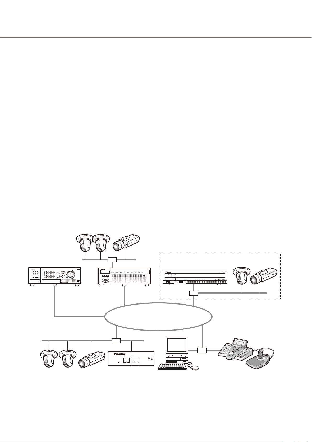
The PC Software Package WV-ASM200 (hereinafter this software) is designed for integrated management of
multiple Panasonic network disk recorders and digital disk recorders (hereinafter recorders), network interface
unit (hereinafter encoders) and network cameras (hereinafter cameras) connected to a network such as a LAN
or the Internet, and runs on the Microsoft® Windows® operating system.
Refer to the "Compatible devices" section (☞ page 5) for the devices compatible with this software.
By using this software on a personal computer (hereinafter PC) via a network, it is possible to display live
images of the cameras, to play images stored on the recorder, and to download image files to the hard disk
drive of the PC.
Software configuration
This software consists of the following 3 applications:
Setup software: The settings required to run the operation software can be configured and managed
with this software.
Operation software: Displaying live images, playback, downloading, searching for images stored on the
recorder, and controlling of the camera is available using this software.
Service software: Reception of Panasonic alarm protocol and auto deletion of the operation log will be
carried out by this software.
This is the resident application (in the system tray). Once the PC is turned on, the
service software runs in the background of the PC.
System configuration
Page 4

4
5
†1: When the system is configured as "System A" in the illustration above, live images from the cameras con-
nected to the recorder can directly be monitored with this software, not through the recorder.
To monitor live images directly from the cameras with this software, the following are necessary.
Register cameras in the recorder.•
The recorder should be used with a single port.•
†2: The system controller is optional.
Important:
Do not use cross cables to connect the PC and each device.•
When connecting multiple system controllers, operation of this software is not guaranteed.•
System specifications
•Recorderregistration: Upto100recorders
•Encoderregistration: Upto64encoders
•Cameraregistration: Upto256cameras
•Decoderregistration: Upto10decoders(ThelicensefortheWV-ASE204isrequired.)
•Userregistration: Upto32users
•Userlevels: 5levels
•Groupregistration: Upto400groups
•Sequenceregistration: Upto10sequences(Upto64stepscanberegisteredforasequence)
•Mapregistration: Upto100maps(Upto64camerascanbeassignedonamap,upto20
registered maps can be used.) (The file size shall be less than 10 MB.
Available file type is JPEG and BMP.)
•Numberofthealarmlogsthatcanbestored: Upto30000logs(Upto1000logscanbedisplayed)
•Numberofthedeviceerrorlogsthatcanbestored: Upto1000logs(Upto1000logscanbedisplayed)
•Numberofthenetworkerrorlogsthatcanbestored: Upto1000logs(Upto1000logscanbedisplayed)
•Numberofthesystemlogsthatcanbestored: Upto1000logs(Upto1000logscanbedisplayed)
•Numberoftheoperationlogsthatcanbestored: Upto100000logs(Upto1000logscanbedisplayed)
•Numberofsearchresultsthatcanbedisplayed: Upto1000logs search results (Up to 200 results for
VMD search)
Note:
Number of PCs that can concurrently access a single recorder differs depending on choosing whether or •
not to use "Live window" and the model of the recorder in use.
Recorder Use of "Live window"
Yes No
ND300 4 6
ND200 2 4
HD300
ND400 8 16
HD600 4 8
NV200 1 1
ASR500
†3
When exceeding the maximum number of concurrent access due to an increase in the number of accesses •
using web browsers or FTP accesses, connection to the recorder may be interrupted and a black screen
may be displayed.
By adding the license for the Extension Software WV-ASE203 (option), it will become possible to expand the •
maximum numbers of registered recorders, encoders and cameras to 100, 64 and 256 respectively. Up to 4
licenses for the WV-ASE203 can be added.
†1
2
†4 †4
3
†2
†1: When displaying images on a 16-screen or
9-screen, only a single PC can access.
†2: When displaying images on a 16-screen, 2 PCs
can access.
†3: Under the following conditions, connection to the
recorder may be interrupted and a black screen
may be displayed.
Event recording and sequence are being oper-•
ated.
The total live rate for each HD300 exceeds •
15 ips. (☞ Page 22)
†4: Note that it varies depending on the system con-
figuration in use.
Page 5

5
Compatible devices
The following devices are compatible with this software.
Important:
Some functions may not work depending on the firmware version of the compatible device. •
Refer to the Panasonic support website (http://security.panasonic.com/pss/security/support/index.html) for
further information.
Note:
Refer to the operating instructions of the recorder in use for the cameras that can be connected to the •
recorder in use.
Compatible recorders
Model Appears in this document as Version Compression
ND300 series ND300 5.20 or later MPEG-4
M-JPEG
H.264
ND200 series ND200 3.30 or later MPEG-4
M-JPEG
H.264
HD300 series HD300 3.44 or later Model-specific
ND400 series ND400 2.20 or later MPEG-4
M-JPEG
H.264
HD600 series HD600 2.06 or later H.264
NV200 series NV200 1.04 or later MPEG-4
M-JPEG
H.264
ASR500 series ASR500 5.9.1901.48362
or later
MPEG-4
M-JPEG
H.264
Compatible encoder
Model Appears in this document as Version Compression
WJ-NT304 NT304 1.32 or later MPEG-4
M-JPEG
WJ-NT314 NT314 1.32 or later MPEG-4
M-JPEG
WJ-GXE500 GXE500 1.30 or later H.264
MPEG-4
M-JPEG
WJ-GXE100 GXE100 1.72 or later H.264
MPEG-4
Compatible cameras
Refer to the Readme.txt on the provided CD-ROM.
Page 6

6
7
Compatible decoder (The license for the WV-ASE204 is required.)
Model Appears in this document as Version Compression
WJ-GXD400 GXD400 2.20 or later H.264
MPEG-4
M-JPEG
About the setup software
An administrator or the registered user who is allowed to display the current settings can log in to the setup
software. Only an administrator can configure the settings.
Even when logging in to the PC as an administrator, it is impossible to launch both the setup software and the
operation software simultaneously. When launching one of them, make sure that the other one is not launched.
The following setup items can be configured using the setup software.
Important:
To use the following functions, it is necessary to add the license for the Extension Software WV-ASE201 •
(option).
Live window•
Map window•
Control using the System Controller WV-CU950•
Refer to Settings relating to the license registration (☞ page 109) for further information about how to add
the license for the Extension Software.
To control the GXD400, it is necessary to register the license for the Extension Software WV-ASE204 •
(option) additionally.
To use the following functions, it is necessary to add the license for the Extension Software WV-ASE• 231
(option).
Face search monitor•
System
Contains settings required for basic operation of this software.
Refer to the "Settings relating to the system" section (☞ page 19) for further information.
Device mng.
Contains settings required to display live images or play recorded images, such as information of the recorders,
the encoders and the cameras.
Refer to the "Settings relating to the device management" section (☞ page 23) for further information.
User mng.
Each user should be defined as an administrator or a normal user in this software.
Information of each user can be managed on this page.
Refer to the "Settings relating to the user management" section (☞ page 53) for further information.
Camera
Contains settings relating to the camera group and the sequence display function.
Refer to the "Settings relating to the cameras" section (☞ page 62) for further information.
Window
Contains settings relating to the live window and the map window.
Refer to the "Settings relating to the window" section (☞ page 69) for further information.
Page 7

7
Event
Contains settings relating to the event action such as displaying of the alarm notification window, sounding the
buzzer, the alarm camera direct window function, displaying of the error notification window together with
sounding the buzzer, etc.
Refer to the "Settings relating to the event action" section (☞ page 80) for further information.
Comm
Contains the settings relating to the communication and the alarm notification using the Panasonic alarm protocol.
Refer to the "Settings relating to the communication" section (☞ page 83) for further information.
Controller
Configures the camera number, group number, sequence number, all of which are used when controlling
through the system controller.
Refer to "Settings relating to the controller" (☞ page 85) for further information.
Maintenance
Displaying of the version of this software and management of the logs/the setup data are available.
Refer to the "Settings relating to the maintenance" section (☞ page 94) for further information.
Registration of license
Registers the license to use this software and to add extensive options.
Refer to the "Settings relating to the license registration" section (☞ page 109) for further information.
Standard accessories
CD-ROM .......................................................... 1 pc.
Installation guide ............................................. 1 pc.
Activation Key Card ......................................... 1 pc.
Important:
The provided CD-ROM contains the installer of this software, the operating instructions (PDF), the setup •
instructions (PDF) and the Readme.txt.
Prior to installation, read the Readme.txt.
This software will not work if the license is not registered. After installing the software on the PC in use, reg-•
ister the license.
Page 8

8
9
About the user manuals
There are two PDF manuals (the operating instructions and the setup instructions) and the installation guide
(leaflet).
This PDF manual contains descriptions of how to install this software and of how to configure the required settings to operate this software for an administrator.
The network settings will be different depending on the settings of the LAN or the Internet service provider.
Refer to the network administrator for further information about the network settings.
Refer to WV-ASM200 Operating Instructions (PDF) for further information about how to operate each function of
this software.
"WV-ASE201" shown in the instructions and illustrations used in this manual indicates the WV-ASE201,
WV-ASE201W.
"WV-ASE202" shown in the instructions and illustrations used in this manual indicates the WV-ASE202,
WV-ASE202W.
"WV-ASE203" shown in the instructions and illustrations used in this manual indicates the WV-ASE203,
WV-ASE203W.
"WV-ASE204" shown in the instructions and illustrations used in this manual indicates the WV-ASE204,
WV-ASE204W.
The descriptions in the following pages are based on the assumption that Microsoft® Windows® 7 Professional
runs on a PC.
Operation windows may not be the same as those appearing on the pages when a different OS is used or different settings are applied.
When using other OS, refer to the operating instructions of the respective OS.
System requirements
It is recommended to install this software on a PC that meets the following system requirements.
OS†1: Microsoft® Windows® 8 Pro (32-bit)
Microsoft® Windows® 8 Pro (64-bit)
Microsoft® Windows® 7 Professional SP1 (32-bit)
Microsoft® Windows® 7 Professional SP1 (64-bit)
Microsoft® Windows Vista® Business SP2 (32-bit)
Microsoft® Windows Vista® Business SP2 (64-bit)†2
OS language: English, French, Spanish, German, Italian, Russian, Chinese (Simplified
Chinese)
Computer: IBM PC/AT Compatible
CPU: Intel® CoreTM i5-2400, 2500
Intel® CoreTM i7-860 or faster
When adding the license for WV-ASE202 and displaying images on a
64-screen: Intel CoreTM i7-2600
Memory: 3 GB or more
When using more than one live window: 4 GB
Graphics accelerator: VRAM 512 MB or more (256 MB minimum), compatible with
DirectX® 9.0c
CD-ROM drive: Necessary to install this software
Required hard disk space: Approx. 3 GB
Monitor: 1280x800 pixels or more (1920x1080 pixels recommended), 24-bit True
color or better (Full color recommended)
Network interface: 100/1000 Mbps Network interface card must be installed
Web browser: Windows® Internet Explorer® 7.0, 8.0, 9.0
†4
†2
†2 †3
†2 †7
†2 †3 †7
†2 †7
†3 †7
†5
†6
Page 9

9
†1: This software is designed based on the default style or the font size of Microsoft® Windows Vista®,
Microsoft® Windows® 7 and Microsoft® Windows® 8.
When the display style or the font size of Microsoft® Windows® 7 or Microsoft® Windows Vista® is changed
from the default, it may be possible that the layout of this software collapses.
†2: When using Microsoft® Windows Vista®, Microsoft® Windows® 7 or Microsoft® Windows® 8, refer to
"Readme.txt" for further information about the system requirements, precautions, etc.
†3: Operates in WOW64 (32-bit mode).
†4: It is required that Microsoft® SQL Server 2005 Express Edition SP4 (when using Windows Vista / Windows
7) or Microsoft® SQL Server® 2012 Service Pack 1 (SP1) Express (when using Windows 8) is installed on the
PC to use this software.
It is necessary to prepare other disk space exclusively as storage for database and files downloaded from
the recorder in addition to the required disk space for installation of this software.
†5: The network settings on the PC must meet those of the network environment where the PC is connected.
Operations of this software on a PC with two network interface cards or more will not be covered by the
warranty.
†6: Supported versions of the web browser and restrictions will vary depending on the connected devices.
Refer to the operating instructions of the devices for further information.
†7: The "Windows classic" style is not available as a theme used for the desktop customization. Select
"Windows Vista" on Windows Vista and "Windows 7 Basic" on Windows 7 respectively.
Important:
This software must be installed by the administrator. Otherwise, any problems will not be covered by the •
warranty.
This software uses Microsoft•
7) or Microsoft® SQL Server® 2012 Service Pack 1 (SP1) Express (when using Windows 8) as the database.
Operation of this software on remote desktop is not guaranteed.•
While running this software, do not log out of the PC nor shut down the PC. Otherwise, operation of this •
software may become unstable.
Do not use other applications, especially heavy load types, while this software is running. Otherwise, the •
CPU overload and the shortage of resources will cause malfunction and insufficient performance.
When no sound card is installed, the buzzer will not sound at an alarm/error occurrence. The audio trans-•
mission/reception function is also unavailable.
Use of 2-byte characters for a user name causes installation failure. Create a user name with 1-byte alpha-•
numeric characters and perform installation.
This software is not compatible with Windows XP mode for Microsoft•
®
SQL Server 2005 Express Edition SP4 (when using Windows Vista / Windows
®
Windows® 7.
Page 10

10
11
Recommended camera settings when monitoring MPEG-4 or H.264 images
Set the "Max bit rate (per 1 client)" setting of the camera as below according to the PC in use.
When the set values for "Max bit rate (per 1 client)" is larger than the value below, this software may not work
correctly. In this case, terminate this software forcibly, and then set an appropriate bit rate.
■ When monitoring MPEG-4 images (VGA)
CPU Recommended bit rate
®
CoreTM i5-2400 2048 kbps (30 fps)
Intel
* "Normal" shall be selected for the image quality of the camera.
■ When monitoring H.264 images (VGA)
CPU Recommended bit rate
®
CoreTM i5-2400 1536 kbps (30 fps)
Intel
■ When adding the license for WV-ASE202 and displaying images on a 64-screen (QVGA)
CPU Recommended bit rate
®
CoreTM i7-2600 1024 kbps (30 fps)
Intel
Trademarks and registered trademarks
Microsoft, Windows, Windows Vista, Internet Explorer and DirectX are either registered trademarks or trade-•
marks of Microsoft Corporation in the United States and/or other countries.
Intel, Pentium and Intel Core are trademarks or registered trademarks of Intel Corporation in the United •
States and other countries.
Adobe, Adobe logos, and Reader are either registered trademarks or trademarks of Adobe Systems •
Incorporated in the United States and/or other countries.
All other trademarks identified herein are the property of their respective owners.•
Abbreviations
These are descriptions of the basic terms used in these operating instructions.
Microsoft® Windows Vista® Business SP2 (32-bit) and Microsoft® Windows Vista® Business SP2 (64-bit) are
described as Windows Vista.
Microsoft
described as Windows 7.
Microsoft® Windows® 8 Pro (32-bit) and Microsoft® Windows® 8 Pro (64-bit) are described as Windows 8.
®
Windows® 7 Professional SP1 (32-bit) and Microsoft® Windows® 7 Professional SP1 (64-bit) are
Page 11

11
Document convention
These are descriptions of the basic terms used in these operating instructions.
Administrator
Indicates a person responsible for management and
operation of this software.
User
Indicates a person who operates this software. Each
user should be defined as an administrator or a registered user in this software. Only a user who is registered as an administrator can configure and maintain
this software.
Recorder
Indicates Panasonic network disk recorders or digital
disk recorders.
Refer to the "Compatible devices" section (☞ page 5)
for the devices compatible with this software.
Encoder
Indicates Panasonic network interface unit.
Refer to the "Compatible devices" section (☞ page 5)
for the devices compatible with this software.
Fixed camera
Indicates cameras without the panning and tilting
functions.
PTZ camera
Indicates cameras featuring the panning, tilting and
zooming functions.
Fisheye camera
Indicates Panasonic Fisheye network cameras.
Live image
Indicates live images from the camera.
Group display
Images from cameras can be registered as a group
and displayed by groups.
Sequence
Images of each registered group can be displayed
sequentially in the order determined in advance.
The sequence function of this software is available
only for live image display.
EL-zoom
Indicates the zoom function available when displaying
live or recorded images.
While the zoom function of the camera enlarges
images using the zoom lens of the camera, the
EL-zoom function enlarges images by processing
images on this software.
Clicking a point in the EL-zoomed image moves the
displayed EL-zoomed image by positioning the
clicked point as the center point.
Camera operation
Indicates the operations of the camera connected,
such as panning/tilting, zooming, focusing, starting
the preset function (move to the preset position),
starting the selected auto mode function, brightness
adjustment, preset registration and AUX control.
Network playback
Recorded images on the recorder can be played via a
network.
Manual recording
Indicates recording that is performed by clicking the
[REC START] button and the [REC STOP] button.
Decoder
Indicates Panasonic network video decoders. Refer
to the "Compatible devices" section (☞ page 5) for
the devices compatible with this software.
Direct image reception
Indicates that image reception directly from a camera
registered in the network disk recorder, not through
the recorder.
Download
Indicates file (recorded image on the recorder) transfer from the recorder to a PC using the FTP function.
Image file
Indicates downloaded recorded image from the
recorder.
File playback
Indicates playback of image files using the viewer
software.
Page 12

12
13
Notification function using the Panasonic
alarm protocol
Indicates the function that uses alarm/event notification transmitted from the device using Panasonic
alarm protocol.
Application log
Indicates logs filed each time when this software
obtains information about an alarm or a device error
occurrence from the recorder, or when an operation
of this software is made, etc.
The application logs are filed as distinct logs; alarm
log, device error log, network error log, system log
and operation log.
Recorder log
Indicates logs filed each time when a recorder error
or a network error occurred in the recorder.
The recorder logs are generated in the recorder.
The recorder logs are filed as distinct logs; error log,
access log, event log and network log.
M-JPEG
Indicates a video codec that compresses video fields
from the camera into independent JPEG images
sequentially.
Network load will be reduced comparing with the
method that obtains JPEG images independently
from the camera. However, the transmission rate will
fluctuate depending on the state of the camera.
Some cameras phrase this video codec as just
"JPEG".
REC event
Indicates the reason (an event or an operation) why
the recording started.
The recording event will be described as follows.
Manual, schedule, emergency, site alarm, terminal
alarm, command alarm, VMD, video loss, SD memory
backup
SD memory recording (SD memory data)
Indicates the function featured in some Panasonic's
cameras that transfers images saved on the SD memory card on the camera to the recorder.
Recorded images transferred to the recorder are
described as "SD memory data" in these operating
instructions.
The recording time of SD memory data will be displayed based on the clock of the camera.
Setup software
Indicates the application used to configure the settings required to run the operation software.
Operation software
Indicates the application used for displaying live
images of the recorders, encoders and cameras,
playback, downloading, searching for images stored
on the recorder, and controlling the camera.
Operation window
Indicates the window used to operate all functions
except for configurations of this software.
Live window
Indicates the window used only for the group or
sequence display of live images.
Map window
Indicates the window that displays a map with the
registered camera icons.
It is possible to display live images from the desired
camera by clicking the respective camera icon on the
map.
SD memory download
Indicates the function featured in some Panasonic's
cameras that transfers H.264 video files (mp4 files)
saved on the SD memory card equipped with the
camera to a PC using the FTP function.
Smooth & fast playback mode
Indicates the mode that can play back all the frames
without skipping when playing back Step 2 and
Step 3.
License
Registration is surely required before using this software. Refer to the provided "Activation Key Card" to
obtain and register the "Registration Key". The
obtained "Registration Key" can be used only on the
PC in which the software is installed.
Demo edition
It is possible to use all the functions of the designated
software for 90 days by registering the license for the
demo edition.
Face search monitor
This window is used to perform operation relating to
the face search. The real time alarm display, face/
alarm search and age/gender report will be executed
on this window.
Page 13
13
Operation flow
To run the operation software, do the following in advance.
z
x
c
v
b
Installation of this software
➜ ➜ ➜ ➜ ➜ ➜ ➜ ➜
Startup the setup software
Obtainment of license
("Registration Key") (☞ Activation Key Card)
Registration of the license
("Registration Key")
Settings relating to the system
(☞ page 19)
Settings relating to the device
management (☞ page 23)
Settings relating to the user management
(☞ page 53)
z Install this software. Refer to the "Installation" sec-
tion (☞ page 14) for further information.
x Start the setup software. Refer to the "Start/exit
the setup software" section (☞ page 16) for further
information.
c Obtain the "Registration Key" by following the
instructions on the provided Activation Key Card.
v Register the "Registration Key" of this software.
Refer to steps 2 - 5 of the "Start/exit the setup
software" section (☞ page 16) for further information.
Important:
Be sure to perform the registration procedure on •
the PC in use. To use the demo edition (available
for 90 days), it is required to register the
"Registration Key" of the demo edition. Refer to
the Readme.txt on the provided CD-ROM for further information.
n
m
,
Settings relating to the cameras
(☞ page 62)
Settings relating to the window
(☞ page 69)
Settings relating to the face search
(☞ page 74)
Settings relating to the event action
(☞ page 80)
Settings relating to the communication
(☞ page 83)
Settings relating to the controller
(☞ page 85)
Settings relating to the maintenance
(☞ page 94)
Settings relating to the license registration
(☞ page 109)
Setup software ended.
Exceptional settings for the firewall
b Configure the settings required to run this soft-
ware.
Note:
When a message window is displayed by clicking •
the button on the window, refer to the "Displayed
messages and solutions" section (☞ page 116)
and follow the instructions.
n If necessary, register the "Registration Key" for
the Extension Software WV-ASE201 (option).
m Exit from the setup software.
Refer to the "Start/exit the setup software" sec-
tion (☞ page 16) for further information.
, When using the download function or the
Panasonic alarm protocol function (alarm notification, event notification), configure the exceptional
settings of Windows Firewall. Refer to the
"Exceptional settings of Windows Firewall" section (☞ page 111) for further information.
Close the setup software and start operation
using the operation software.
Start operation
Page 14

14
15
Installation/uninstallation
Installation
Important:
Before installing this software, make sure that no other Panasonic disk recorder management software such •
as WV-AS65, WV-ASM10 or WV-ASM100/ASM100L is installed on the PC.
When the other Panasonic disk recorder management software and this software are on the same PC, oper-
ations of this software will not be covered by the warranty.
When reinstallation is necessary, uninstall the existing software before starting the reinstallation. An over-•
write installation may cause unstable operations. When this software is uninstalled, the setup data of this
software will be deleted. When the setup data is necessary, save the setup data before uninstalling this soft-
ware.
Step 1
Insert the provided CD-ROM into the CD-ROM drive on the PC.
Step 2
Double-click "SQLServerSetup.exe" in the folder "1 SQLServer".
The installer of "Microsoft
"Microsoft® SQL Server® 2012 Service Pack 1 (SP1) Express" (when using Windows 8) will be launched.
Install the software by following the instructions displayed on the monitor.
Step 3
Double-click "setup.exe" in the folder "2 Disk Recorder Management Software".
The installer of "Disk Recorder Management Software" will be launched.
Install the software by following the instructions displayed on the monitor.
When installed with the ALL option, the executable files, etc. will be copied on a newly created folder
"C:\Program Files\Panasonic\ASM200".
Step 4
Configure the exceptional settings of Windows Firewall.
Refer to the "Exceptional settings of Windows Firewall" section (☞ page 109) for further information.
Step 5
Reboot the PC.
When completing steps 1 - 5, reboot the PC to complete the installation.
Important:
Before starting operation using the operation software, configure the settings required to operate the opera-•
tion software, such as user registration, device registration, using the setup software.
®
SQL Server 2005 Express Edition SP4" (when using Windows Vista / Windows 7) or
Page 15

15
Uninstallation
Important:
When this software is uninstalled, the setup data of this software will be deleted. When the setup data is •
necessary, save the setup data before uninstalling this software. Refer to the "Save the setup data as a
backup" section (☞ page 105) for how to save the setup data.
The data downloaded from the recorder will not be deleted even when this software is uninstalled.•
Microsoft•
SQL Server® 2012 Service Pack 1 (SP1) Express (when using Windows 8) will not be deleted even when this
software is uninstalled.
When it is necessary to uninstall them after uninstalling this software, uninstall them in the following order. If
a message window is displayed to ask you to exit other applications when uninstalling the software, click
the [Cancel] button to cancel the uninstallation. Uninstall the software again after stopping the respective
services.
Refer to the manuals of the operating system in use for how to stop the services.
Step 1
Open "Programs and Features" in "Control Panel".
Step 2
Select "WV-ASM200" from the presently installed programs and click the [Uninstall] button.
The uninstall program will be launched and the wizard will be displayed.
®
SQL Server 2005 Express Edition SP4 (when using Windows Vista / Windows 7) or Microsoft®
Step 3
Uninstall the software by following the instructions displayed on the monitor.
Page 16
16
17
Start/exit the setup software
Important:
Registration of the license is required before using •
this software. This software will not work if the
license is not registered.
Register the license for the software after confirm-•
ing that the network adapter of the PC is enabled.
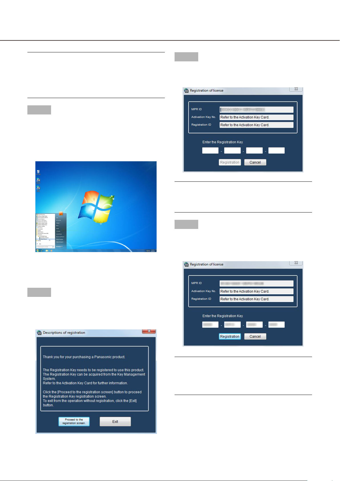
Step 1
Select "Setup Software" from "start" menu ("start" "All Programs" - "Panasonic" - "WV-ASM200" "Setup Software") or double-click the "Setup
Software" icon on the desktop to launch the setup
software.
Step 3
Enter the "Registration Key" obtained from the Key
Management System.
Important:
The "Registration Key" can be used only on a PC •
that displays "MPR ID" (used to obtain the key) on
its screen. It cannot be used on other PCs.
The explanation window for registration will be →
displayed.
Step 2
After reading the message on the explanation window, click the [Proceed to the registration screen.]
button.
Step 4
Click the [Registration] button.
The confirmation window for registration will be →
displayed.
Important:
It is impossible to register the "Registration Key" •
of the extension software (option).
Be sure to perform the registration procedure on •
the PC in use.
Page 17

17
Step 5
Step 7
Click the [OK] button.
Step 6
Enter the registered user name and password.
Only an administrator is registered when operat- →
ing the software just after the installation. Enter
"ADMIN" for "User name" and "12345" for "Password" respectively.
Click the [OK] button.
The setup window will be displayed. →
Step 8
Click the [×] button at the top right of the setup window to exit the setup software.
The setup software will be closed. →
Important:
To enhance the security, change the password for •
an administrator before running the software.
It is recommended to change the password for •
the administrator periodically. Refer to the
"Settings relating to the administrator
[Administrator setup]" section (☞ page 54) for fur-
ther information.
Page 18
18
19
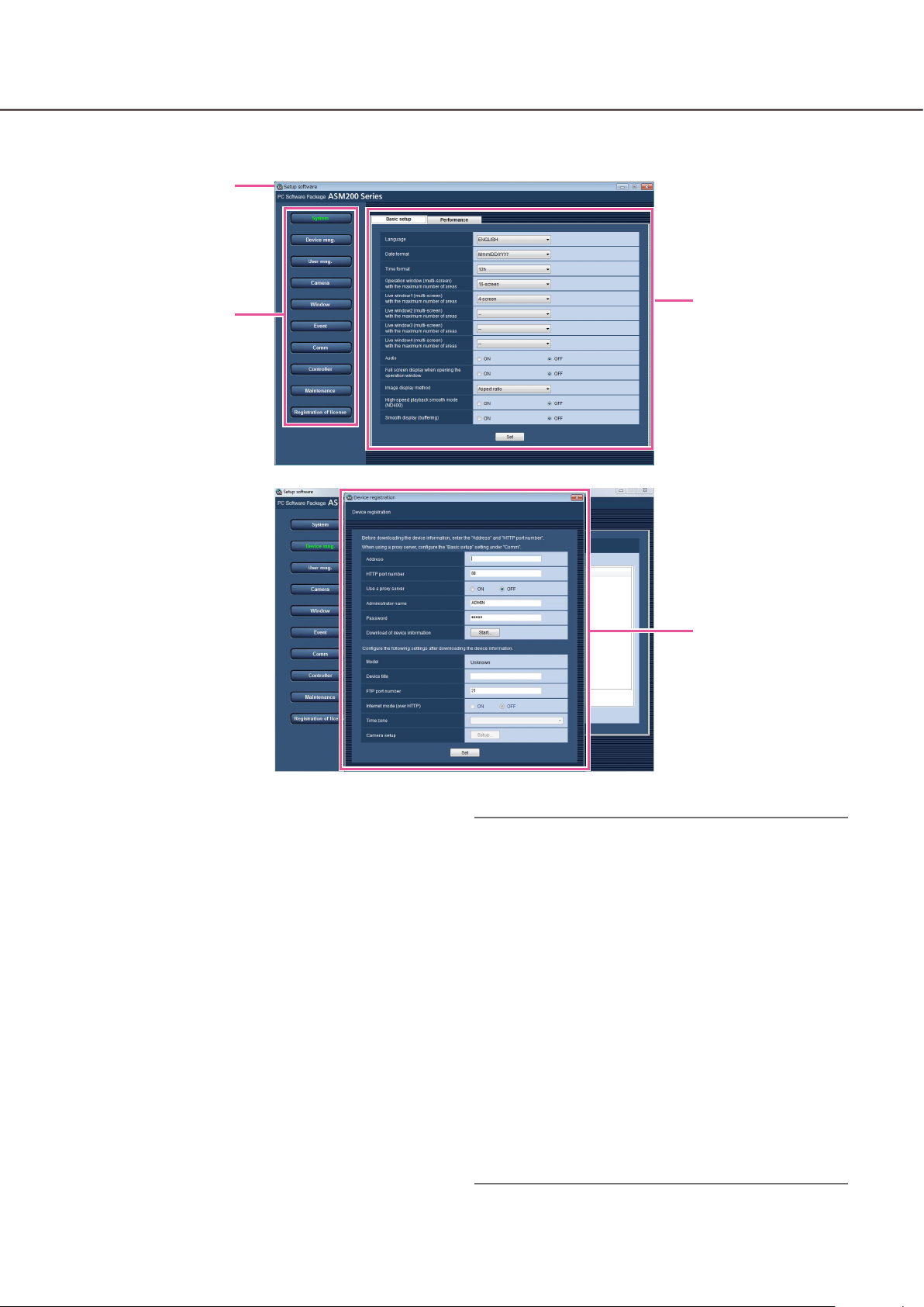
Setup window
When the setup software starts, the setup window will be displayed.
Title bar
Menu buttons
Setup page
Detailed setup page
(sub window)
■ Title bar
The title of the setup software will be displayed.
■ Menu buttons
When the menu button is clicked, the respective
setup page will be displayed.
■ Setup page
The setup page respective to the clicked menu button will be displayed.
When multiple tabs are displayed in the setup page,
click the desired tab to display the respective tab
page.
■ Detailed setup page (sub window)
When the button on the setup page that leads to the
detailed settings is clicked, the detailed setup page
will be displayed in the newly opened window (sub
window).
Important:
To save and apply the edited settings on the •
setup page, it is necessary to click the [Set] button.
When the [Set] button is not clicked, the edited
settings will not be saved and applied.
To save and apply the edited settings on the •
detailed setup page, it is necessary to click the
[Set] button. When the sub window is closed without clicking the [Set] button, the edited settings
will not be saved and applied.
When the edited setting is invalid, the setup item •
for which the invalid setting is entered/selected
will be displayed in red. When there is any setup
item displayed in red, correct the invalid setting.
Some setup items will be displayed after purchas-•
ing the Extension Software WV-ASE201,
WV-ASE202, WV-ASE231 and adding the license.
Page 19

19
Settings relating to the system
Operating language, date format, time format, maximum number of areas when displaying on a multi-screen,
audio, automatic full screen of the operation window and maximum refresh interval can be configured.
Select the operating language, date format, time format, etc. [Basic setup]
Click the [System] button, and then click the [Basic setup] tab to display the "Basic setup" page.
■ Language
Select the operating language.
JAPANESE, ENGLISH, FRANÇIS, ESPAÑOL,
DEUTSCH, ITALIANO, RUSSIAN, CHINESE
Default: ENGLISH
Important:
The language setting will not be applied even •
when the [Set] button is clicked.
To apply the edited language setting, restart this
software.
■ Date format
Select a date format to be displayed from the following.
Example: Apr/01/2011
YYYY/MM/DD: 2011/04/01
MM/DD/YYYY: 04/01/2011
Mmm/DD/YYYY: Apr/01/2011
DD/MM/YYYY: 01/04/2011
DD/Mmm/YYYY: 01/Apr/2011
Default: Mmm/DD/YYYY (DD/MM/YYYY when the
software in use is European specification)
Note:
The date format will be applied to the following to •
display time and date.
Status bar •
Information display area •
Alarm notification message window •
Event notification message window •
(Each) Log list •
Refer to WV-ASM200 Operating Instructions (PDF)
for further information about them.
■ Time format
Select a time format to be displayed from the following.
Example: 3 o'clock in the afternoon
12 h: 3:00:00 PM
24 h: 3:00:00
Default: 12h (24h when the software in use is
European specification)
Note:
The time format will be applied to the following to •
display time and date.
Status bar •
Information display area •
Alarm notification message window •
Error notification window •
(Each) Log list •
Refer to WV-ASM200 Operating Instructions (PDF)
for further information about them.
Page 20

20
21
■ Operation window (multi-screen) with the
maximum number of areas
Select a multi-screen pattern of the operation window
from the following.
1-screen/4-screen/9-screen/16-screen
Default: 16-screen
■ After the license for the Extension Software
WV-ASE202 is added, select a setting value
from the following.
1-screen/4-screen/9-screen/16-screen/25-screen/36screen/49-screen/64-screen
■ Live window (multi-screen) with the
maximum number of areas (Available after
the license for the WV-ASE201 is added)
Select a multi-screen pattern of the live window from
the following.
--/1-screen/4-screen/9-screen/16-screen
Default: 4-screen
Note:
When not using the live window, select "--".•
■ Live window1 (multi-screen) with the
maximum number of areas (Available after
the licenses for the WV-ASE201 and
WV-ASE202 are added)
Select a maximum number of areas (multi-screen pattern) of Live window 1 from the following.
--/ 1-screen/ 4-screen/ 9-screen/ 16-screen/
25-screen/ 36-screen/ 49-screen/ 64-screen
Default: 4-screen
■ Live window2 (Available after the licenses
for the WV-ASE201 and WV-ASE202 are
added)
Select a maximum number of areas (multi-screen pattern) of Live window 2 from the following.
--/ 1-screen/ 4-screen/ 9-screen/ 16-screen/
25-screen/ 36-screen/ 49-screen/ 64-screen
Default: --
■ Live window4 (Available after the licenses
for the WV-ASE201 and WV-ASE202 are
added)
Select a maximum number of areas (multi-screen pattern) of Live window 4 from the following.
--/ 1-screen/ 4-screen/ 9-screen/ 16-screen/
25-screen/ 36-screen/ 49-screen/ 64-screen
Default: --
■ Audio
Determine whether to use or not use the audio reception/transmission function.
ON: Use the audio reception/transmission function.
OFF: Not use the audio reception/transmission func-
tion.
Default: OFF
Note:
When receiving images from ASR500, audio •
reception/transmission function will not be used
even though "ON" is selected.
■ Full screen display when opening the
operation window
Select whether or not to automatically provide full
screen display of the operation window immediately
after logging in.
This item is enabled when a group is set as a default
screen.
ON: Full screen display enabled
OFF: Full screen display disabled
Default: OFF
■ Image display area
Select how to display the image area.
Aspect ratio: The aspect ratio of images will be maintained.
Scaling: The displayed images will be enlarged/
reduced in the whole of the image area.
Same size display: The images will be displayed with
the original size without enlargement/reduction.
Default: Aspect ratio
■ Live window3 (Available after the licenses
for the WV-ASE201 and WV-ASE202 are
added)
Select a maximum number of areas (multi-screen pattern) of Live window 3 from the following.
--/ 1-screen/ 4-screen/ 9-screen/ 16-screen/
25-screen/ 36-screen/ 49-screen/ 64-screen
Default: --
Note:
When receiving images from ASR500, • "Aspect
ratio" will automatically be applied to display
Images in the image display area even if selecting
"Scaling" or "Same size display".
Page 21

21
■ High-speed playback smooth mode (ND400)
Select whether or not to use the high-speed playback
smooth mode.
ON: Use
OFF: Not use
Default: OFF
■ Smooth display (buffering)
Select whether or not to use the buffer for images.
ON: Images will temporarily be stored in the PC for
smooth display.
OFF: Images will not be stored in the PC and be dis-
played in real time.
Default: OFF
Note:
The setting will be validated only when using the •
operation window in 1-/4-/9-/16-screen.
When "ON" is selected, image display delay may •
occur.
■ [Set] button
The edited settings will be saved and applied.
Page 22

22
23
Set the maximum refresh interval [Performance]
Click the [System] button, and then click the [Performance] tab to display the "Performance" page.
Enter a number of images to be refreshed per second.
Note:
Change the value for "JPEG/VGA (Live/Playback)" according to your PC environment. •
Intel® CoreTM i5: 240 ips
Intel® CoreTM i7: 300 ips
(For reference) Intel® CoreTM 2 Duo 2.66 GHz: 160 ips
When the resolution is QXGA (2048x1536), SXVGA•
maximum refresh interval will be x1/10, x1/4, x2/3 or x4 of the set value.
†1: When "Partial" is selected for the scan mode of NP100x, the resolution will be 960x720.
When displaying on a multi-screen, the set value divided by the number of areas will be the maximum •
refresh interval per area of a multi-screen.
When "60 ips" is set for the maximum refresh interval, the maximum refresh interval per area when display-
ing on a 4-screen will be 15 ips.
When displaying images directly from the cameras, the camera whose refresh interval (set for "Refresh inter-•
val (JPEG)" on the "Camera setup" window (☞ page 28)) is the smallest value among the cameras in use for
displaying on a multi-screen will be applied as the maximum refresh interval per area.
The actual refresh interval may become slower than the set refresh interval depending on the network envi-•
ronment, the settings of the camera and the set maximum refresh interval on the "Performance" page.
The maximum refresh interval of MPEG-4 or H.264 images cannot be controlled with this software. Refer to •
the "Recommended camera settings when monitoring MPEG-4 or H.264 images" section (☞ page 8) for further information.
When a program of the recorder changed the recording rate, images sometimes may not be refreshed •
exactly at the set refresh interval.
Select the value of 15 ips or less for the live rate for an HD300 (ASM200xHD300 (Live))•
†1
(1280x960), SVGA (800x600), QVGA (320x240), the
■ JPEG/VGA (Live/Playback)
Enter a number among the following for the maximum
refresh interval for the whole system when displaying
JPEG images of VGA size (640x480) from the HD300.
1 ips - 300 ips
Default: 100 ips
Note:
When receiving images from ASR500, images will •
be displayed at the image refresh rate of the camera or the recorder.
■ HD300 (Live)
Enter a number among the following for the maximum
refresh interval for the whole system when displaying
live images from the HD300.
1 ips - 15 ips
Default: 5 ips
■ [Set] button
The configured settings will be saved.
Page 23
23
Settings relating to the device management
Devices can be registered and information of the registered devices can be edited or deleted.
Refer to the "System specifications" section (☞ page 4) for number of the devices that can be registered.
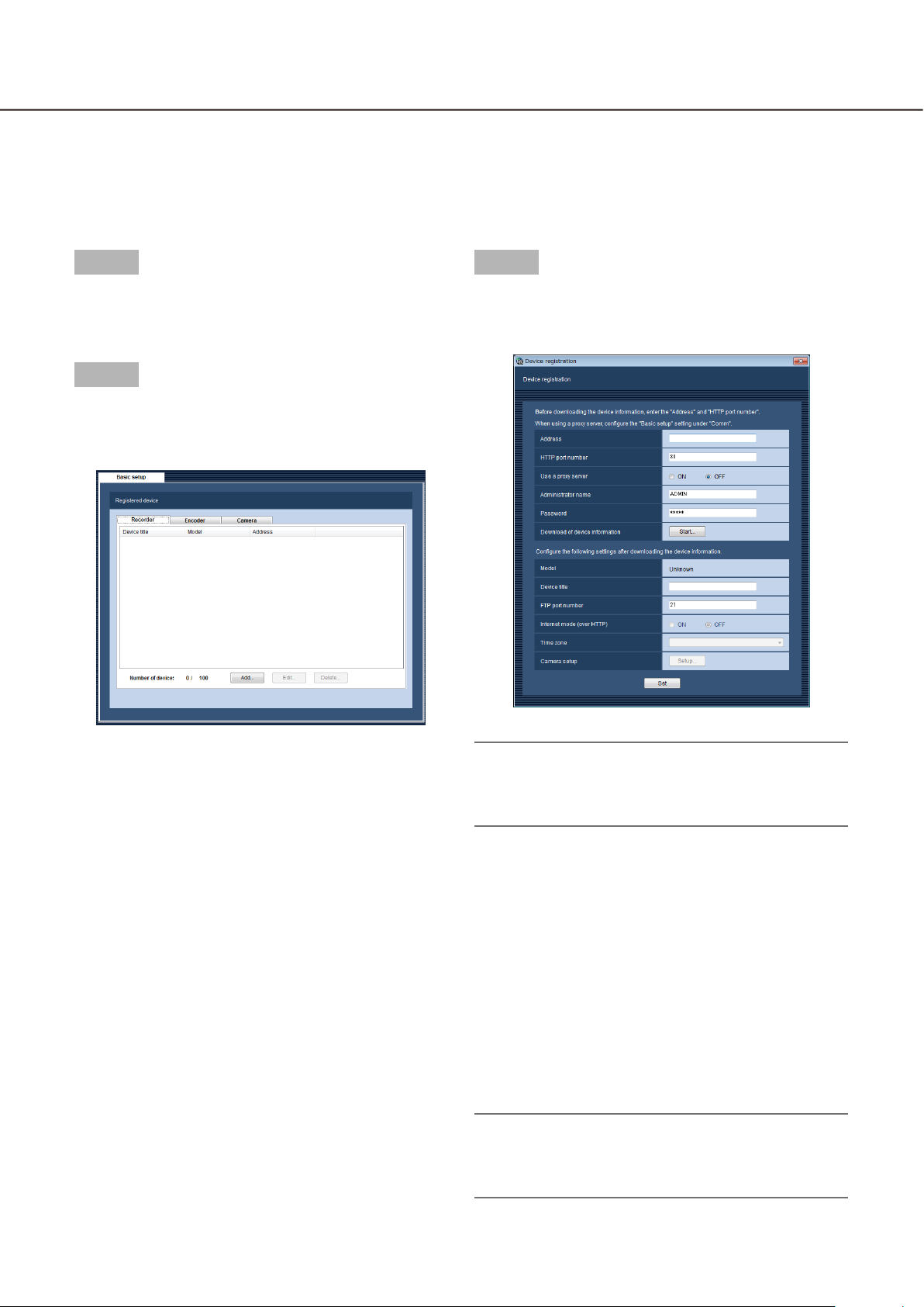
Register a recorder [Basic setup]
Step 1
Click the [Device mng.] button.
The "Basic setup" page of "Device mng." will be →
displayed.
Step 2
Click the [Recorder] tab.
The "Registered device" window of the recorder →
will be displayed.
Step 3
Click the [Add...] button.
The "Device registration" window will be dis- →
played.
The following are descriptions about each item displayed on the "Basic setup" page.
■ Registered device
Titles, model numbers and addresses of the registered recorders will be displayed in list form.
■ Number of device
Number of the registered recorders will be displayed.
■ [Add...] button
The "Device registration" window will be displayed.
■ [Edit...] button
The "Device registration" window of the recorder
selected from the list will be displayed.
■ [Delete...] button
The recorder selected from the list will be deleted.
Note:
The [Add...] button will become unavailable when •
reached the maximum number of encoder registration.
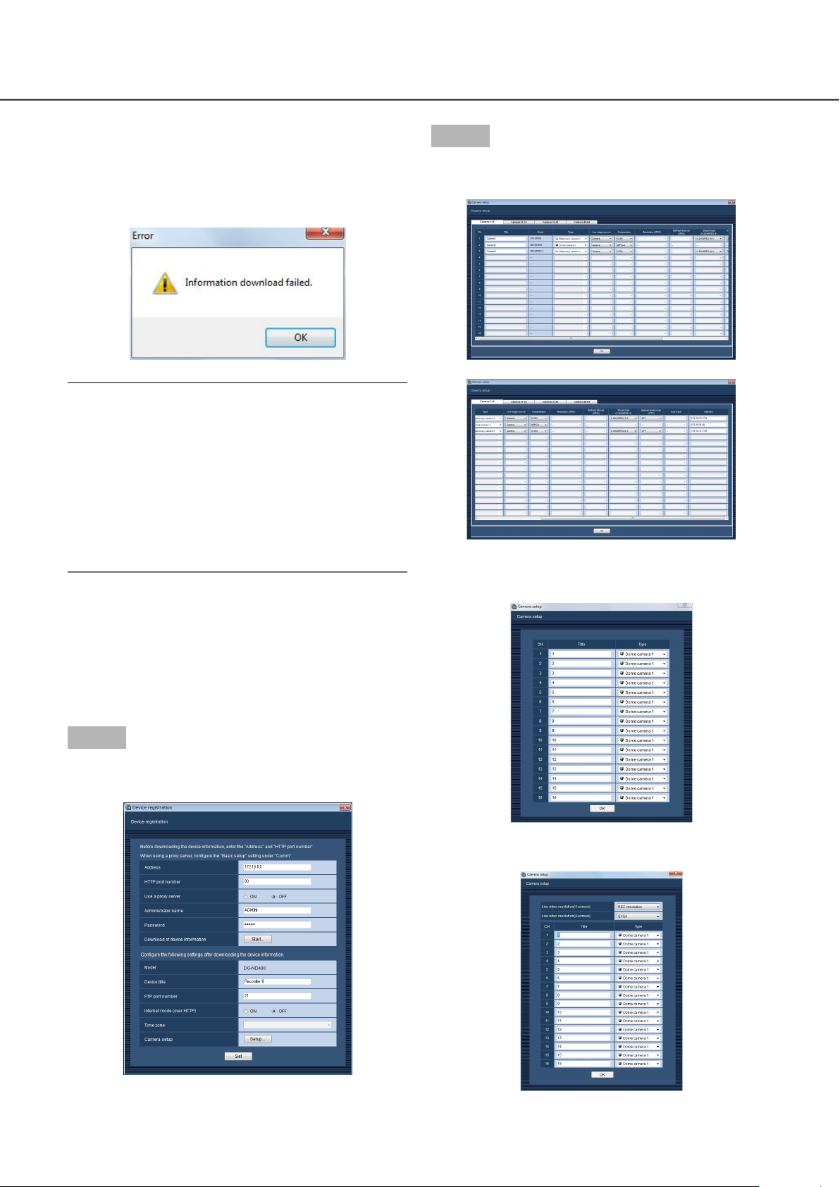
The following are descriptions about each item displayed on the "Device registration" window.
■ Address
Enter the IP address of the recorder.
Enter up to 255 alphanumeric characters for the
address.
■ HTTP port number
Enter a number from 1 to 65535 for the HTTP port
number.
Default: 80
Note:
The default HTTP port number set for ASR500 is •
"22609". When using without changing the
default, change to "22609" from "80".
Page 24

24
25
■ Use a proxy server
Determine whether to use a proxy server to connect
the recorder or not.
ON: Use a proxy server
OFF: Not use a proxy server
Default: OFF
Important:
When displaying images directly from cameras, •
live images will be received without using a proxy
server.
Note:
The proxy server address can be set on the [Basic •
setup] tab of the "Comm" page (☞ page 83).
■ Administrator name
Enter the administrator name registered in the
recorder. Enter 4 - 14 alphanumeric characters for the
administrator name.
Default: ADMIN
Note:
It is impossible to use the following administrator •
names: administrator, guest, operator, users,
nogroup, shutdown, shadow, hdusers.
After downloading the device information, when •
the device is recognized as the HD300, it
becomes impossible to enter this item.
■ Password
Enter the administrator password registered in the
recorder. The entered password will be displayed as
"*". Enter 4 - 8 alphanumeric characters for the password.
Default: 12345
Note:
The default password set for ASR500 is •
"admin256". When using without changing the
default, change to "admin256" from "12345".
■ Device title
Enter the recorder title. Enter up to 16 characters.
The following characters are unavailable for the
recorder title.
!$ % ' < = > @ [ \ ] ^ _ ` { | } ~
■ FTP port number
Enter a number from 1 to 65535 for the FTP port
number.
Default: 21
Important:
It is necessary to make the selected port number •
available when "Windows Firewall" Windows Vista
or Windows 7 is on.
Refer to the "Exceptional settings of Windows
Firewall" section (☞ page 111) for how to make
the selected port number available.
When using ASR500, it is impossible to specify •
the FTP port number.
■ Internet mode (over HTTP)
Select this item when receiving MPEG-4 or H.264
images via the Internet. It is possible to transmit
MPEG-4 or H.264 images while maintaining the same
setting of the broadband router as that when transmitting JPEG images.
ON: Receive MPEG-4 or H.264 images with audio
using the HTTP port.
OFF: Receive MPEG-4 or H.264 images with audio
using the UDP port.
Default: OFF
Important:
It is possible to select this item when the record-•
ing in use is the ND400 (Version 2.40 or later), the
HD600 (Version 2.04 or later) or the NV200
(Version 1.04 or later).
When "ON" is selected for "Internet mode (over •
HTTP)", all the current image sources will be
changed to the recorder.
■ [Start...] button
Device information will be downloaded based on the
settings of "Address", "HTTP port number" and "Use
a proxy server".
■ Model
The model number contained in the downloaded
recorder information will be displayed. "Unknown"
will be displayed when recorder information is not
downloaded yet.
Note:
When using ASR500, MPEG-4 or H.264 images •
with audio will be received using the UDP port.
Page 25

25
■ Time zone
Select the time zone of the place where the recorder
is installed. Time zone can be selected only when the
device in use is ASR500.
Default: Time zone set for the PC.
■ [Setup...] button
The "Camera setup" window will be displayed.
The [Setup...] button will be unavailable until recorder
information is downloaded.
Important:
Make sure that the settings on the "NW Camera •
Setup" page of the setup menu of the recorder
are completed before downloading the recorder
information. When the recorder is not configured
correctly, downloading of the recorder information
may be impossible.
When the settings of the setup menu of the •
recorder are edited, download the recorder information again.
■ [Set] button
The edited settings will be saved and applied.
Step 4
Complete the settings of "Address", "HTTP port number", "Use a proxy server", "Administrator name" and
"Password".
Step 6
Click the [OK] button.
The downloading status window will be displayed. →
To cancel downloading the recorder information,
click the [Cancel] button on the displayed downloading status window.
Step 5
Click the [Start...] button.
Step 7
The message window will be displayed when download process ended.
<When download of the device information is
successfully completed>
The confirmation window will be displayed.
Click the [OK] button.1.
The confirmation window will close. →
Go to step 8.2.
Page 26
26
27
<When download of the device information
failed>
The error message window will be displayed.
Confirm the content of the message indicated in 1.
the window.
Note:
Check if the entered device information is correct. •
When the information has been edited correctly,
the connected device or the version of the connected device may not be compatible with this
software. Refer to the "Compatible devices" section (☞ page 5) for further information.
Refer to the "When the [Start...] button on the •
setup page of "Device mng." is clicked” section
(☞ page 118) for further information about the displayed messages and solutions.
Click the [OK] button.2.
The error window will close. →
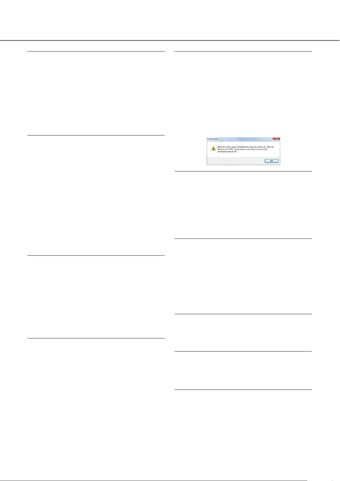
Step 9
Click the [Setup...] button.
The "Camera setup" window will be displayed. →
<The camera setup window of network disk
recorder>
When the device registration will be displayed 3.
again, confirm the settings.
Then, download the device information again.4.
Step 8
Complete the setting of "Device title" and "FTP port
number".
<The camera setup window of the HD300>
<The camera setup window of the HD600>
Page 27

27
The following are descriptions about each item displayed on the "Camera setup" window.
■ [Camera CH] tabs
Click the tab to change the setup page.
Important:
When using ASR500 and even 64 or more camera •
channels are registered in ASR 500 as in the
example below, only 64 camera channels of them
can be registered in this software. Make sure that
the number of the camera channels to be registered are 64 or less.
Example) Register a single GXE500 and 63 cam-
eras to use the total of 67 channels.
Note:
The displayed tab varies with recorders.•
When the recorder in use is the HD300 or the •
HD600, this tab will not be displayed.
When the recorder in use is the NV200, the tabs •
for up to 32 channels will be displayed, but it is
impossible to edit the unused or invalid channels.
■ CH
The camera channel numbers will be displayed.
■ Title
The camera titles contained in the downloaded
recorder information will be displayed. The displayed
titles can be edited.
Enter up to 24 characters for the title. The following
characters are unavailable for the camera title.
!$ % ' < = > @ [ \ ] ^ _ ` { | } ~
Note:
If these unavailable characters are used for the •
camera title on the HD600 or NV200, they will be
replaced with spaces.
■ Model
The model numbers of the cameras contained in the
downloaded recorder information will be displayed.
"--" will be displayed for the camera channel for
which no camera is set.
Note:
If the camera has been registered on the NV200, •
"WV-" or "WJ-" of the model number will be
abbreviated .
■ Type
Indicates the type and the corresponding icon of the
camera obtained from the recorder.
There are 16 types: Dome camera 1, Dome camera 2,
Dome camera 3, Dome camera 4, Dome camera 5,
Dome camera 6, Dome camera 7, Dome camera 8,
Dome camera 9, Dome camera10, Stationary camera
1, Stationary camera 2, Stationary camera 3,
Stationary camera 4, Fisheye camera 1, Fisheye camera 2.
Default: Differs depending on the model number of
the camera when the recorder in use is NV200.
When the recorder in use is the ND400, the type
will be "Dome camera 1", "Stationary camera 1",
"Fisheye camera 1" or "Fisheye camera 2".
When another network disk recorder is used,
"Dome camera 1" or "Stationary camera 1" will be
indicated. When the recorder in use is the HD300
or the HD600, "Dome camera 1" will be indicated.
Note:
The camera icon registered in the map will not •
change even when the camera type is changed.
■ Live image source
Select whether to display live images directly from the
cameras or through the recorder by selecting
"Camera" or "Recorder".
Recorder: It is possible to view live images through
the recorder.
Camera: It is possible to view live images directly
from the camera.
It is necessary to register the cameras on the
recorder even if "Camera" is selected. Refer to the
operating instructions of the recorder in use for
how to register the cameras.
Default: When the camera in use is compatible with
the direct image reception function, the default is
"Camera".
When the camera in use is not compatible with
the direct image reception function, the default is
"Recorder".
Note:
When "Camera" is selected, live images from the •
camera can be displayed even when "OFF" is
selected for "LIVE VIDEO" of the setup menu of
the recorder.
A message window may be displayed if "Camera" •
is selected. Refer to the "When the live image
source is selected on the "Camera setup" window" section (☞ page 119) for further information
about the displayed messages and solutions.
Page 28

28
29
■ Compression
Select the image compression type of the camera.
The image compression type can be selected only
when using an MPEG-4 or H.264 camera and
"Camera" is selected for "Live image source".
M-JPEG: Live images will be displayed in the
M-JPEG format.
MPEG-4: Live images will be displayed in the
MPEG-4 format.
H.264: Live images will be displayed in the H.264 for-
mat.
Default: Indicates the setting configured on the
recorder.
Refer to the operating instructions of the recorder
in use for how to configure the compression type
of the camera on the recorder.
■ Resolution (JPEG)
Select the resolution from the following.
The resolution setting can be configured only when
"Camera" is selected for "Live image source" and
"M-JPEG" is selected for "Compression".
Auto†1: Images whose resolution is VGA (640x480)
will automatically be fit into the area when displaying on a 1-screen or a 4-screen. Images whose
resolution is QVGA (320x240) will automatically be
fit into the area when displaying on a 9-screen or
a 16-screen.
QVGA: Images whose resolution is QVGA (320x240)
will automatically be fit into the area regardless of
the screen pattern.
QVGA/ 320x180: Images whose resolution is QVGA
(320x240, 320x180 in the 16:9 mode) will automatically be fit into the area regardless of the
screen pattern.
VGA: Images whose resolution is VGA (640x480) will
automatically be fit into the area regardless of the
screen pattern.
VGA/ 640×360/ 800×600: Images whose resolution is
VGA (640×480, 640x360 in the 16:9 mode,
800x600 in the 4:3 (800x600) mode) will automatically be fit into the area regardless of the screen
pattern.
800x600: Images whose resolution is 800x600 will
automatically be fit into the area regardless of the
screen pattern.
1280×960†2: Images whose resolution is 1280x960
will automatically be fit into the area regardless of
the screen pattern.
1280×960/ 1280×720: Images whose resolution is
1280x960 (1280×720 in the 16:9 mode) will automatically be fit into the area regardless of the
screen pattern.
1920×1080†3: Images whose resolution is 1920x1080
will automatically be fit into the area regardless of
the screen pattern.
2048×1536
will automatically be fit into the area regardless of
the screen pattern.
Default: When "Camera" is selected for "Live image
source" and "M-JPEG" is selected for
"Compression", "Auto" is the default. When the
selected parameters for "Live image source" and
"Compression" are other than "Camera" and
"M-JPEG" respectively, "--" is the default.
†1: When the image capture mode of NP502 or
NW502 is 3 megapixels or more, images whose
resolution is VGA will be displayed regardless of
the screen pattern.
When the image capture mode of a Fisheye cam-
era is 3 megapixels or more, images whose resolution is 2048x1536 will be displayed regardless of
the screen pattern.
†2: When "Partial" is selected for the scan mode of
NP100x, the resolution will be 960x720.
†3 When the image capture mode is not 2 megapix-
els (in the 16:9 mode), 3 megapixels (in the 16:9
mode), 2M Double Panorama (in the 16:9 mode)
or 2M Panorama (in the 16:9 mode), the image will
not be displayed in the resolution set for the camera or an error may occur.
†4 When the image capture mode is not 3 megapix-
els (in the 4:3 mode) or 3M Fisheye (in the 4:3
mode), the image will not be displayed in the resolution set for the camera or an error may occur.
†4
: Images whose resolution is 2048x1536
■ Refresh interval (JPEG)
Determine the refresh interval of the camera (number
of images to be refreshed per second).
The refresh interval setting can be configured only
when "Camera" is selected for "Live image source"
and "M-JPEG" is selected for "Compression".
Auto/0.1 ips/0.2 ips/0.3 ips/0.5 ips/1 ips/2 ips/3 ips/
5 ips/10 ips/15 ips/All
When "Auto" is selected, an appropriate refresh interval will be applied according to the value set for
"JPEG/VGA (Live/Playback)" on the "Performance"
page.
When "All" is selected, the refresh interval will be
"30 ips".
Default: When "Camera" is selected for "Live image
source" and "M-JPEG" is selected for
"Compression", "Auto" is the default.
When the selected parameters for "Live image
source" and "Compression" are other than
"Camera" and "M-JPEG" respectively, "--" is the
default.
Page 29
29
Note:
"0.1 ips", "0.2 ips", "0.3 ips" and "0.5 ips" may be •
unavailable depending on the model of the camera.
The actual refresh interval may become slower •
than the set refresh interval depending on the network environment, the settings of the camera and
the set maximum refresh interval on the
"Performance" page.
Refer to the "Set the maximum refresh interval •
[Performance]" section (☞ page 22) for how to set
the maximum refresh interval.
■ Stream type (H.264/MPEG-4)
Select the stream type from the following.
The stream type setting can be set only when
"Camera" is selected for "Live image source" and
"H.264" or "MPEG-4" is selected for "Compression".
Auto: Apply H.264/MPEG-4(1) for the stream type
when displaying images on a 1-screen. Apply
H.264/MPEG-4(2) for the stream type when displaying images on a 4-screen, 9-screen or
16-screen.
H.264/MPEG-4(1): Always apply H.264/MPEG-4(1) for
the stream type.
H.264/MPEG-4(2): Always apply H.264/MPEG-4(2) for
the stream type.
Default: H.264/MPEG-4(1)
Note:
Refer to the operating instructions of the camera •
in use for how to configure the settings for the
steam type of "H.264/MPEG-4(1)" and "H.264/
MPEG-4(2)".
When selecting "AUTO", it is possible to eliminate •
the network bandwidth and lower the CPU load of
the PC by performing the settings of H.264/
MPEG-4 (1) for 1-screen display or by performing
the settings of H.264/MPEG-4 (2) for multi-screen
display.
■ Internet mode (over HTTP)
Select which of the HTTP or UDP port is used when
receiving MPEG-4 or H.264 images with audio when
"Camera" is selected for "Live image source".
ON: Receive MPEG-4 or H.264 images with audio
using the HTTP port.
OFF: Receive MPEG-4 or H.264 images with audio
using the UDP port.
Default: "OFF" when "Camera" is selected for "Live
image source" and "- -" otherwise
Note:
It is impossible to use this mode when the cam-•
eras in use are WV-NP244, WV-NP1000/NP1004,
WV-NS202, WV-NS202A, WV-NF284,
WV-NW484, WV-NS950/NS954, WV-NW960/
NW964, WV-NP304, WV-NF302.
If "ON" is selected for "Internet mode (over •
HTTP)", the following dialog box will be displayed
when the [OK] button is clicked. When the Internet
mode is used, select "ON" for "Internet mode
(over HTTP)" on the cameras.
■ Auto track
Select whether to trace the route set in advance automatically when "Camera" is selected for "Live image
source".
ON: Trace the route automatically.
OFF: Not trace the route automatically.
Default: --
Note:
This mode is available only when the camera in •
use is WV-SC386 or WV-SW396.
When "ON" is selected for "Auto track", the "+" •
mark will be displayed while panning/tilting is
being controlled using the WV-CU950 and the
lock-on function will work by pressing the top button.
Auto track is unavailable while panning/tilting is •
being controlled.
■ Address
The address of the camera contained in the downloaded recorder information will be displayed.
Note:
When the Internet mode is used, images may not •
be displayed correctly unless the address is
changed to what can be accessed from the
Internet.
■ Live video resolution(1-screen)
Select the resolution of live images on a 1-screen
from the following.
REC resolution: Live images are transmitted with the
resolution applied at the time of recording.
QVGA: Live images are transmitted in the QVGA size.
Default: REC resolution
Page 30

30
31
■ Live video resolution(4-screen)
Select the resolution of live images on a 4-screen
from the following.
REC resolution: Live images are transmitted with the
resolution applied at the time of recording.
QVGA: Live images are transmitted in the QVGA size.
Default: QVGA
Note:
Refer to the operating instructions of the HD600 •
for further information about the settings of trans-
mission (such as the transmission rate and the
image quality) when "REC resolution" or "QVGA"
is selected.
Sometimes, live images may not be displayed •
even when the transmission rate of the recorder is
too low.
While live images are being displayed in
sequence, select "QVGA" for "Live video
resolution(1-screen)" and "Live video resolution(4-
screen)".
■ [OK] button
The "Camera setup" window will be closed.
Step 10
Click the [OK] button after completing the settings.
The "Camera setup" window will close. →
Note:
The edited settings will not be saved and applied •
even when the "Camera setup" window is closed
by clicking the [OK] button. To save and apply the
settings, click the [Set] button on the "Device reg-
istration" window after closing the "Camera
setup" window.
Step 11
Click the [Set] button on the "Device registration"
window.
The "Device registration" window will close and →
the settings will be saved and applied. The regis-
tered recorder will be displayed in the list of the
registered device.
Page 31

31
Edit the registered recorder information [Basic setup]
Step 1
Display the "Registered device" window of the
recorder. (☞ page 23)
Step 2
Select the recorder whose information is to be edited,
and then click the [Edit...] button.
The "Device registration" window will be displayed.
Step 3
Click the [Set] button after editing the information.
Refer to the "Register a recorder [Basic setup]" section (☞ page 23) for further information.
The "Device registration" window will close and →
the settings will be saved and applied.
Delete the registered recorder [Basic setup]
Step 1
Display the "Registered device" window of the
recorder. (☞ page 23)
Step 2
Select the recorder to be deleted.
Step 3
Click the [Delete...] button.
The confirmation window will be displayed. →
Step 4
Click the [OK] button.
The device information will be deleted. →
Page 32

32
33
Register an encoder [Basic setup]
Step 1
Click the [Device mng.] button.
The "Registered device" window will be dis- →
played.
Step 2
Click the [Encoder] tab.
The "Registered device" window of the encoder →
will be displayed.
Step 3
Click the [Add...] button.
The "Device registration" window will be dis- →
played.
The following are descriptions about each item displayed on the "Registered device" window of the
encoder.
■ Registered device
Titles, model numbers and addresses of the registered encoders will be displayed in list form.
■ Number of device
Number of the registered encoders will be displayed.
■ [Add...] button
Click this button to display the "Device registration"
window.
■ [Edit...] button
The "Device registration" window of the encoder
selected from the list will be displayed.
■ [Delete...] button
The encoder selected from the list will be deleted.
Note:
The [Add...] button will become unavailable when •
reached the maximum number of encoder registration.
The following are descriptions about each item displayed on the "Device registration" window of the
encoder.
■ Address
Enter the IP address of the encoder.
Enter up to 255 alphanumeric characters.
■ HTTP port number
Enter a number among the following for the HTTP
port number.
1 - 65535
Default: 80
■ Use a proxy server
Determine whether to use or not use a proxy server to
connect the encoder.
ON: Use a proxy server
OFF: Not use a proxy server
Default: OFF
Page 33

33
Note:
The proxy server address can be set on the [Basic •
setup] tab of the "Comm" page (☞ page 83).
■ Administrator name
Enter the administrator name registered in the
encoder. Enter 1 - 32 alphanumeric characters for the
administrator name.
Default: admin
■ Password
Enter the administrator password registered in the
encoder. The entered password will be displayed as
"*". Enter 4 - 32 alphanumeric characters for the
password.
Default: 12345
■ [Setup...] button
The "Camera setup" window will be displayed.
The [Setup...] button will be unavailable until encoder
information is downloaded.
■ [Set] button
The edited settings will be saved and applied.
Step 4
■ [Start...] button
Device information will be downloaded based on the
settings of "Address", "HTTP port number" and "Use
a proxy server".
■ Model
The model number of the encoder contained in the
device information downloaded from the encoder will
be displayed.
"Unknown" will be displayed when encoder information is not downloaded yet.
■ Device title
Enter the encoder title.
Enter up to 16 characters.
The following characters are unavailable for the
encoder title.
!$ % ' < = > @ [ \ ] ^ _ ` { | } ~
■ Internet mode (over HTTP)
Select which of the HTTP or UDP port is used when
receiving MPEG-4 or H.264 images with audio.
ON: Receive MPEG-4 or H.264 images with audio
using the HTTP port.
OFF: Receive MPEG-4 or H.264 images with audio
using the UDP port.
Default: OFF
Complete the settings of "Address", "HTTP port number", "Use a proxy server", "Administrator name" and
"Password".
This mode is available only when the encoder in use
is GXE500.
If "ON" is selected for "Internet mode (over HTTP)",
the following dialog box will be displayed when the
[Set] button is clicked. When the Internet mode is
used, select "ON" for "Internet mode (over HTTP)" on
the encoders.
Page 34

34
35
Step 5
Step 7
Click the [Start...] button.
Important:
When the settings of the setup menu of the •
encoder are edited, download the encoder infor-
mation again.
The message window will be displayed when download process ended.
<When download of the encoder information
is successfully completed>
Click the [OK] button.1.
The confirmation window will close. →
Go to step 8.2.
<When downloading of the encoder
information failed>
Confirm the content of the message indicated in 1.
the window.
Step 6
Click the [OK] button.
The downloading status window will be displayed. →
To cancel downloading the encoder information,
click the [Cancel] button on the "Now downloading..." window.
Note:
Check if the entered device information is correct. •
When the information has been edited correctly,
the connected device or the version of the connected device may not be compatible with this
software. Refer to the "Compatible devices" section (☞ page 5) for further information.
Click the [OK] button.2.
The error window will close. →
When the device registration will be displayed 3.
again, confirm the settings.
Then, download the device information again.4.
Page 35

35
Step 8
Enter for "Device title".
Step 9
Click the [Setup...] button.
The "Camera setup" window will be displayed. →
■ CH
The camera channel numbers will be displayed.
■ Title
Enter the camera title.
When editing the camera title, enter up to 16 characters.
The following characters are unavailable for the camera title.
!$ % ' < = > @ [ \ ] ^ _ ` { | } ~
Default: Camera channel number
■ Type
Indicates the type and the corresponding icon of the
camera.
There are 16 types: Dome camera 1, Dome camera 2,
Dome camera 3, Dome camera 4, Dome camera 5,
Dome camera 6, Dome camera 7, Dome camera 8,
Dome camera 9, Dome camera10, Stationary camera
1, Stationary camera 2, Stationary camera 3,
Stationary camera 4, Fisheye camera 1, Fisheye camera 2.
Default: Dome camera 1
Note:
The camera icon registered in the map will not •
change even when the camera type is changed.
<The camera setup window of the GXE500>
<The camera setup window of the GXE100>
<The camera setup window of the NT304 / NT314>
The following are descriptions about each item displayed on the "Camera setup" window of the
encoder.
■ Compression
Select the image compression method from the following.
M-JPEG: Live images will be displayed in the
M-JPEG format.
MPEG-4: Live images will be displayed in the
MPEG-4 format.
H.264: Live images will be displayed in the H.264 for-
mat.
Default: "H.264" when the encoder in use supports
the H.264 format "MPEG-4" when the encoder in
use does not support the H.264 format
■ Resolution (JPEG)
Select the resolution from the following.
The resolution setting can be configured only when
"M-JPEG" is selected for "Compression".
Auto: Images whose resolution is VGA (640x480) will
automatically be fit into the area when displaying
on a 1-screen or a 4-screen.
Images whose resolution is QVGA (320x240) will
automatically be fit into the area when displaying
on a 9-screen or a 16-screen.
Page 36

36
37
QVGA/ 320x180: Images whose resolution is QVGA
(320x240, 320x180 in the 16:9 mode) will auto-
matically be fit into the area regardless of the
screen pattern.
VGA/ 640x360: Images whose resolution is VGA
(640x480, 640x360 in the 16:9 mode) will auto-
matically be fit into the area regardless of the
screen pattern.
Default: When "M-JPEG" is selected for
"Compression", "Auto" is the default.
When "Compression" is other than "M-JPEG",
"--" is the default.
■ Refresh interval (JPEG)
Determine the refresh interval of the camera (number
of images to be refreshed per second).
The refresh interval setting can be configured only
when "M-JPEG" is selected for "Compression".
Auto/0.1 ips/0.2 ips/0.3 ips/0.5 ips/1 ips/2 ips/3 ips/
5 ips/10 ips/15 ips/All
When "Auto" is selected, an appropriate refresh interval will be applied according to the value set for
"JPEG/VGA (Live/Playback)" on the "Performance"
page.
When "All" is selected, the refresh interval will be
"30 ips".
Default: When "M-JPEG" is selected for
"Compression", "Auto" is the default.
When "Compression" is other than "M-JPEG",
"--" is the default.
Note:
Refer to the operating instructions of the encoder •
in use for how to configure the settings for the
steam type of "H.264/MPEG-4(1)" and "H.264/
MPEG-4(2)".
■ [OK] button
Click this button to close the "Camera setup" window.
Step 10
Click the [OK] button after completing the settings.
The "Camera setup" window will close. →
Note:
The edited settings will not be saved and applied •
even when the "Camera setup" window is closed
by clicking the [OK] button.
To save and apply the settings, click the [Set] button on the "Device registration" window after closing the "Camera setup" window.
Step 11
Click the [Set] button on the "Device registration"
window.
The "Device registration" window will close and →
the settings will be saved and applied.
The registered encoder will be displayed in the list
of the registered devices.
Note:
The actual refresh interval may become slower •
than the set refresh interval depending on the net-
work environment, the settings of the camera and
the set maximum refresh interval on the
"Performance" page.
Refer to the "Set the maximum refresh interval •
[Performance]" section (☞ page 22) for how to set
the maximum refresh interval.
■ Stream type (H.264/MPEG-4)
Select the stream type from the following.
The stream type setting can be set only when "H.264"
or "MPEG-4" is selected for "Compression" on the
encoder supporting the H.264 format.
H.264/MPEG-4(1): Always apply H.264/MPEG-4(1) for
the stream type.
H.264/MPEG-4(2): Always apply H.264/MPEG-4(2) for
the stream type.
Default: H.264/MPEG-4(1)
Page 37

37
Edit the registered encoder information [Basic setup]
Step 1
Display the "Registered device" window of the
encoder. (☞ page 32)
Step 2
Select the encoder whose information is to be edited
from the list of the registered devices, and then click
the [Edit...] button.
The "Device registration" window will be dis- →
played.
Step 3
Click the [Set] button after editing the information.
Refer to the "Register an encoder [Basic setup]" section (☞ page 32) for further information.
The "Device registration" window will close and →
the settings will be saved and applied.
Page 38

38
39
Delete the registered encoder [Basic setup]
Step 1
Display the "Registered device" window of the
encoder. (☞ page 32)
Step 2
Select the encoder to be deleted from the list of the
registered devices.
Step 3
Click the [Delete...] button.
The confirmation window will be displayed. →
Step 4
Click the [OK] button.
The device information of the selected encoder →
will be deleted.
Page 39

39
Register a camera [Basic setup]
Step 1
Click the [Device mng.] button.
The "Registered device" window will be dis- →
played.
Step 2
Click the [Camera] tab.
The "Registered device" window of the camera →
will be displayed.
Step 3
Click the [Add...] button.
The "Device registration" window will be dis- →
played.
The following are descriptions about each item displayed on the "Registered device" window of the
camera.
■ Registered device
Titles, model numbers and addresses of the registered cameras will be displayed in list form.
■ Number of device
Number of the registered cameras will be displayed.
■ [Add...] button
Click this button to display the "Device registration"
window.
■ [Edit...] button
The "Device registration" window of the camera
selected from the list will be displayed.
■ [Delete...] button
The camera selected from the list will be deleted.
Note:
The [Add...] button will become unavailable when •
reached the maximum number of camera registration.
The following are descriptions about each item displayed on the "Device registration" window of the
camera.
■ Address
Enter the IP address of the camera.
Enter up to 255 alphanumeric characters.
■ HTTP port number
Enter a number among the following for the HTTP
port number.
1 - 65535
Default: 80
■ Use a proxy server
Determine whether to use or not use a proxy server to
connect the camera.
ON: Use a proxy server
OFF: Not use a proxy server
Default: OFF
Page 40

40
41
Note:
The proxy server address can be set on the [Basic •
setup] tab of the "Comm" page (☞ page 83).
OFF: Receive MPEG-4 or H.264 images with audio
using the UDP port.
Default: OFF
■ Administrator name
Enter the administrator name registered in the camera. Enter 1 - 32 alphanumeric characters for the
administrator name.
Default: admin
■ Password
Enter the administrator password registered in the
camera. The entered password will be displayed as
"*". Enter 4 - 32 alphanumeric characters for the
password.
Default: 12345
■ [Start...] button
Device information will be downloaded based on the
settings of "Address", "HTTP port number" and "Use
a proxy server".
■ Model
The model number of the camera contained in the
device information downloaded from the camera will
be displayed.
"Unknown" will be displayed when camera information is not downloaded yet.
Note:
It is impossible to use this mode when the cam-•
eras in use are WV-NP244, WV-NP1000/NP1004,
WV-NS202, WV-NS202A, WV-NF284,
WV-NW484, WV-NS950/NS954, WV-NW960/
NW964, WV-NP304, WV-NF302.
If "ON" is selected for "Internet mode (over •
HTTP)", the following dialog box will be displayed
when the [OK] button is clicked. When the Internet
mode is used, select "ON" for "Internet mode
(over HTTP)" on the cameras.
■ [Setup...] button
The "Camera setup" window will be displayed.
The [Setup...] button will be unavailable until camera
information is downloaded.
■ [Set] button
The edited settings will be saved and applied.
■ Auto track
Select whether to trace the route set in advance automatically.
ON: Trace the route automatically.
OFF: Not trace the route automatically.
Default: OFF
Note:
This mode is available only when the camera in •
use is WV-SC386 or WV-SW396.
When "ON" is selected for "Auto track", the "+" •
mark will be displayed while panning/tilting is
being controlled using the WV-CU950 and the
lock-on function will work by pressing the top but-
ton.
Auto track is unavailable while panning/tilting is •
being controlled.
■ Internet mode (over HTTP)
Select which of the HTTP or UDP port is used when
receiving MPEG-4 or H.264 images with audio.
ON: Receive MPEG-4 or H.264 images with audio
using the HTTP port.
Step 4
Complete the settings of "Address", "HTTP port number", "Use a proxy server", "Administrator name" and
"Password".
Page 41

41
Step 5
Click the [Start...] button.
<When download of the camera information is
successfully completed>
Click the [OK] button.1.
The confirmation window will close. →
When the information has been downloaded from 2.
a stationary camera or PTZ camera, proceed to
Step 8-1.
When the information has been downloaded from
a Fisheye camera, proceed to Step 8-2.
Important:
When the settings of the setup menu of the cam-•
era are edited, download the camera information
again.
Step 6
Click the [OK] button.
The downloading status window will be displayed. →
To cancel downloading the camera information,
click the [Cancel] button on the displayed downloading status window.
<When download of the camera information
failed>
Click the [OK] button on the error message win-1.
dow and check if the information on the "Device
registration" window has been edited correctly.
Note:
Check if the entered device information is correct. •
When the information has been edited correctly,
the connected device or the version of the connected device may not be compatible with this
software. Refer to the "Compatible devices" section (☞ page 5) for further information.
Step 7
The message window will be displayed when download process ended.
Click the [OK] button.2.
The error window will close. →
When the device registration will be displayed 3.
again, confirm the settings.
Then, download the device information again.4.
Page 42

42
43
Step 8-1
Click the [Setup...] button.
The "Camera setup" window will be displayed. →
The following are descriptions about each item displayed on the "Camera setup" window of the camera.
■ Title
Enter the camera title.
When editing the camera title, enter up to 16 characters.
The following characters are unavailable for the camera title.
!$ % ' < = > @ [ \ ] ^ _ ` { | } ~
Default: 1
■ Type
Indicates the type and the corresponding icon of the
camera.
There are 16 types: Dome camera 1, Dome camera 2,
Dome camera 3, Dome camera 4, Dome camera 5,
Dome camera 6, Dome camera 7, Dome camera 8,
Dome camera 9, Dome camera10, Stationary camera
1, Stationary camera 2, Stationary camera 3,
Stationary camera 4, Fisheye camera 1, Fisheye camera 2.
Default: Differs depending on the model number of
the camera.
Note:
The camera icon registered in the map will not •
change even when the camera type is changed.
■ Compression
Select the image compression type of the camera.
Only the MPEG-4 or H.264 cameras can be selected.
M-JPEG: Live images will be displayed in the
M-JPEG format.
MPEG-4: Live images will be displayed in the
MPEG-4 format.
H.264: Live images will be displayed in the H.264 for-
mat.
Default: "H.264" when the camera in use supports the
H.264 format. When the camera in use is an
MPEG-4 camera, the default is "MPEG-4". When
the camera in use is not an MPEG-4 or H.264
camera, the default is "M-JPEG".
Note:
Change the image compression type according to •
the setting of the camera in use.
■ Resolution (JPEG)
Select the resolution from the following.
The resolution setting can be configured only when
"M-JPEG" is selected for "Compression".
Auto†1: Images whose resolution is VGA (640x480)
will automatically be fit into the area when displaying on a 1-screen or a 4-screen.
Images whose resolution is QVGA (320x240) will
automatically be fit into the area when displaying
on a 9-screen or a 16-screen.
QVGA: Images whose resolution is QVGA (320x240)
will automatically be fit into the area regardless of
the screen pattern.
QVGA/ 320x180: Images whose resolution is QVGA
(320x240, 320x180 in the 16:9 mode) will automatically be fit into the area regardless of the
screen pattern.
VGA: Images whose resolution is VGA (640x480) will
automatically be fit into the area regardless of the
screen pattern.
VGA/ 640x360: Images whose resolution is VGA
(640x480, 640x360 in the 16:9 mode) will automatically be fit into the area regardless of the
screen pattern.
VGA/ 640×360/ 800×600: Images whose resolution is
VGA (640x480, 640x360 in the 16:9 mode,
800x600 in the 4:3 (800x600) mode) will automatically be fit into the area regardless of the screen
pattern.
800x600: Images whose resolution is 800x600 will
automatically be fit into the area regardless of the
screen pattern.
1280×960†2: Images whose resolution is 1280x960
will automatically be fit into the area regardless of
the screen pattern.
1280×960/ 1280×720: Images whose resolution is
1280x960 (1280x720 in the 16:9 mode) will automatically be fit into the area regardless of the
screen pattern.
1920×1080†3: Images whose resolution is 1920x1080
will automatically be fit into the area regardless of
the screen pattern.
2048×1536†4: Images whose resolution is 2048x1536
will automatically be fit into the area regardless of
the screen pattern.
Default: When "M-JPEG" is selected for
"Compression", "Auto" is the default.
When "Compression" is other than "M-JPEG",
"--" is the default.
Page 43

43
†1: When the image capture mode of NP502 or
NW502 is 3 megapixels or more, images whose
resolution is VGA will be displayed regardless of
the screen pattern.
When the image capture mode of a Fisheye cam-
era is 3 megapixels or more, images whose reso-
lution is 2048x1536 will be displayed regardless of
the screen pattern.
†2: When "Partial" is selected for the scan mode of
NP100x, the resolution will be 960x720.
†3: When the image capture mode is not 2 megapix-
els (in the 16:9 mode), 3 megapixels (in the 16:9
mode), 2M Double Panorama (in the 16:9 mode)
or 2M Panorama (in the 16:9 mode), the image will
not be displayed in the resolution set for the cam-
era or an error may occur.
†4: When the image capture mode is not 3 megapix-
els (in the 4:3 mode) or 3M Fisheye (in the 4:3
mode), the image will not be displayed in the reso-
lution set for the camera or an error may occur.
■ Refresh interval (JPEG)
Determine the refresh interval of the camera (number
of images to be refreshed per second).
The refresh interval setting can be configured only
when "M-JPEG" is selected for "Compression".
Auto/0.1 ips/0.2 ips/0.3 ips/0.5 ips/1 ips/2 ips/3 ips/
5 ips/10 ips/15 ips/All
When "Auto" is selected, an appropriate refresh interval will be applied according to the value set for
"JPEG/VGA (Live/Playback)" on the "Performance"
page.
When "All" is selected, the refresh interval will be
"30 ips".
Default: When "M-JPEG" is selected for
"Compression", "Auto" is the default.
When "Compression" is other than "M-JPEG",
"--" is the default.
■ Stream type (H.264/MPEG-4)
Select the stream type from the following.
The stream type setting can be set only when "H.264"
or "MPEG-4" is selected for "Compression" on the
camera supporting the H.264 format.
Auto: Apply H.264/MPEG-4(1) for the stream type
when displaying images on a 1-screen. Apply
H.264/MPEG-4(2) for the stream type when displaying images on a 4-screen, 9-screen or
16-screen.
H.264/MPEG-4(1): Always apply H.264/MPEG-4(1) for
the stream type.
H.264/MPEG-4(2): Always apply H.264/MPEG-4(2) for
the stream type.
Default: H.264/MPEG-4(1)
Note:
Refer to the operating instructions of the camera •
in use for how to configure the settings for the
steam type of "H.264/MPEG-4(1)" and "H.264/
MPEG-4(2)".
When selecting "AUTO", it is possible to eliminate •
the network bandwidth and lower the CPU load of
the PC by performing the settings of H.264/
MPEG-4 (1) for 1-screen display or by performing
the settings of H.264/MPEG-4 (2) for multi-screen
display.
■ [OK] button
Click this button to close the "Camera setup" window.
Step 8-2
Click the [Setup...] button.
The "Camera setup" window will be displayed. →
Note:
"0.1 ips", "0.2 ips", "0.3 ips" and "0.5 ips" may be •
unavailable depending on the model of the cam-
era.
The actual refresh interval may become slower •
than the set refresh interval depending on the net-
work environment, the settings of the camera and
the set maximum refresh interval on the
"Performance" page.
Refer to the "Set the maximum refresh interval •
[Performance]" section (☞ page 22) for how to set
the maximum refresh interval.
The details are as follows.
Page 44

44
45
■ Quad streams
Determine whether to use or not use the Quad
streams.
The Quad streams is the function to calibrate the distortion of four fish-eye images in the ratio of 4:3 and
allocate them to each stream number to display in the
H.264 format. To activate this mode, it is necessary
to select "VGA Quad streams" for the image capture
mode of the camera in use.
ON: Use the Quad streams.
OFF: Not to use the Quad streams.
Default: OFF
Note:
Change the stream mode according to the setting •
of the camera in use.
■ Title
Enter the camera title. When editing the camera title,
enter up to 16 characters.
The following characters are unavailable for the camera title.
!$ % ' < = > @ [ \ ] ^ _ ` { | } ~
Default: 1
■ Type
Indicates the type and the corresponding icon of the
camera.
There are 16 types: Dome camera 1, Dome camera 2,
Dome camera 3, Dome camera 4, Dome camera 5,
Dome camera 6, Dome camera 7, Dome camera 8,
Dome camera 9, Dome camera10, Stationary camera
1, Stationary camera 2, Stationary camera 3,
Stationary camera 4, Fisheye camera 1, Fisheye camera 2.
Default: Differs depending on the model number of
the camera.
■ Compression
Select the image compression type of the camera.
The image compression type setting can be configured only when "OFF" is selected for "Quad streams".
M-JPEG: Live images will be displayed in the
M-JPEG format.
H.264: Live images will be displayed in the H.264 for-
mat.
Default: "H.264" when the camera in use supports the
H.264 format.
Note:
Change the stream mode according to the setting •
of the camera in use.
■ Resolution (JPEG)
Select the resolution from the following.
The resolution setting can be configured only when
"OFF" is selected for "Quad streams".
In addition, it is necessary to select "M-JPEG" for
"Compression".
†1
Auto
: Images whose resolution is VGA (640 x 480)
will automatically be fit into the area when displaying on a 1-screen or a 4-screen. Images whose
resolution is QVGA (320 x 240) will automatically
be fit into the area when displaying on a 9-screen
or a 16-screen.
QVGA/ 320x180: Images whose resolution is QVGA
(320x240, 320x180 in the 16:9 mode) will automatically be fit into the area regardless of the
screen pattern.
VGA/ 640x360: Images whose resolution is VGA
(640x480, 640x360 in the 16:9 mode) will automatically be fit into the area regardless of the
screen pattern.
1280×960/1280×720: Images whose resolution is
1280x960 (1280x720 in the 16:9 mode) will automatically be fit into the area regardless of the
screen pattern.
1920×1080†2: Images whose resolution is 1920x1080
will automatically be fit into the area regardless of
the screen pattern.
2048×1536†3: Images whose resolution is 2048x1536
will automatically be fit into the area regardless of
the screen pattern.
Default: When "M-JPEG" is selected for
"Compression", "Auto" is the default.
When "Compression" is other than "M-JPEG",
"--" is the default.
†1 When the image capture mode is "3M Fisheye
[4:3]", the image will be displayed in the resolution
of 2048×1536 regardless of the screen pattern.
†2 When the image capture mode is not "2M Double
Panorama [16:9]" or "2M Panorama [16:9]”, the
image will not be displayed in the resolution set
for the camera or an error may occur.
†3 When the image capture mode is not "3M Fisheye
[4:3]", the error message will be displayed.
■ Refresh interval (JPEG)
Determine the refresh interval of the camera (number
of images to be refreshed per second). The refresh
interval setting can be configured only when
"M-JPEG" is selected for "Compression".
Auto/0.1 ips/0.2 ips/0.3 ips/0.5 ips/1 ips/2 ips/3 ips/
5 ips/10 ips/15 ips/All
Page 45

45
When "Auto" is selected, an appropriate refresh interval will be applied according to the value set for
"JPEG/VGA (Live/Playback)" on the "Performance"
page.
When "All" is selected, the refresh interval will be "30
ips".
Default: When "M-JPEG" is selected for
"Compression", "Auto" is the default.
When "Compression" is other than "M-JPEG", "--" is
the default.
Note:
The actual refresh interval may become slower •
than the set refresh interval depending on the network environment, the settings of the camera and
the set maximum refresh interval on the
"Performance" page.
Refer to the "Set the maximum refresh interval •
[Performance]" section (☞ page 22) for how to set
the maximum refresh interval.
■ Stream type (H.264/MPEG-4)
Select the stream type from the following.
The stream type can be configured only when
"H.264" is selected for "Compression".
Auto: Apply H.264/MPEG-4(1) for the stream type
when displaying images on a 1-screen. Apply
H.264/MPEG-4(2) for the stream type when displaying images on a 4-screen, 9-screen or
16-screen.
H.264/MPEG-4(1): Always apply H.264/MPEG-4(1) for
the stream type.
H.264/MPEG-4(2): Always apply H.264/MPEG-4(2) for
the stream type.
Default: H.264/MPEG-4(1)
■ Channel title
Enter the channel title of each camera.
The channel title setting can be changed only when
"ON" is selected for "Quad streams".
When editing the channel title, enter up to 16 characters. The following characters are unavailable for the
camera title.
!$ % ' < = > @ [ \ ] ^ _ ` { | } ~
Default: Channel number
■ [OK] button
Click this button to close the "Camera setup" window.
Step 9
Click the [OK] button after completing the settings.
The "Camera setup" window will close. →
Note:
The edited settings will not be saved and applied •
even when the "Camera setup" window is closed
by clicking the [OK] button.
To save and apply the settings, click the [Set] but-•
ton on the "Device registration" window after closing the "Camera setup" window.
Step 10
Click the [Set] button on the "Device registration"
window.
The "Device registration" window will close and →
the settings will be saved and applied.
The registered camera will be displayed in the list
of the registered devices.
Note:
Refer to the operating instructions of the camera •
in use for how to configure the settings for the
steam type of "H.264/MPEG-4(1)" and "H.264/
MPEG-4(2)".
When selecting "AUTO", it is possible to eliminate •
the network bandwidth and lower the CPU load of
the PC by performing the settings of H.264/
MPEG-4 (1) for 1-screen display or by performing
the settings of H.264/MPEG-4 (2) for multi-screen
display.
Page 46

46
47
Edit the registered camera information [Basic setup]
Step 1
Display the "Registered device" page of the camera.
(☞ page 39)
Step 2
Select the camera whose information is to be edited
from the list of the registered devices, and then click
the [Edit...] button.
The "Device registration" window will be dis- →
played.
Step 3
Click the [Set] button after editing the information.
Refer to the "Register a camera [Basic setup]" section
(☞ page 39) for further information.
The "Device registration" window will close and →
the settings will be saved and applied.
Page 47

47
Delete the registered camera [Basic setup]
Step 1
Display the "Registered device" page of the camera.
(☞ page 39)
Step 2
Select the camera to be deleted from the list of the
registered devices.
Step 3
Click the [Delete...] button.
The confirmation window will be displayed. →
Step 4
Click the [OK] button.
The device information of the selected camera will →
be deleted.
Page 48

48
49
Register a decoder [Basic setup]
Step 1
Click the [Device mng.] button.
The "Registered device" window will be displayed. →
Step 2
Click the [Decoder] tab.
The "Registered device" window of the decoder →
will be displayed.
Step 3
Click the [Add…] button.
The "Device registration" window will be dis- →
played.
The details are as follows.
Registered device
Titles, model numbers and addresses of the registered decoders will be displayed in list form.
■ Number of device:
Number of the registered decoders will be displayed.
■ [Add...] button
The "Device registration" window will be displayed.
■ [Edit...] button
The "Device registration" window of the decoder
selected from the list will be displayed.
■ [Delete...] button
The decoder selected from the list will be deleted.
Note:
The [Add...] button will become unavailable when •
reached the maximum number of decoder registration.
The details are as follows.
■ Address
Enter the IP address of the decoder. Enter up to 255
alphanumeric characters for the address.
■ HTTP port number
Enter a number among the following for the HTTP
port number.
Between "1" and "65535"
Default: 80
■ Use a proxy server
Determine whether to use a proxy server to connect
the decoder or not.
ON: Use a proxy server
OFF: Not use a proxy server
Default: OFF
Note:
The proxy server address can be set on the [Basic •
setup] tab of the "Comm" page (☞ page 83).
Page 49

49
■ Administrator name
Enter the administrator name registered in the
decoder. Enter 1 - 32 alphanumeric characters for the
administrator name.
Default: admin
■ Password
Enter the administrator password registered in the
decoder. The entered password will be displayed as
"*". Enter 4 - 32 alphanumeric characters for the
password.
Default: 12345
■ [Start...] button
Device information will be downloaded based on the
settings of "Address", "HTTP port number" and "Use
a proxy server".
■ Model
The model number contained in the downloaded
decoder information will be displayed. "Unknown" will
be displayed when decoder information is not downloaded yet.
■ Device title
Enter the decoder title. Enter up to 16 characters for
the device title. The following characters are unavailable for the recorder title.
! $ % ' < = > @ [ \ ] ^ _ ` { | } ~
Step 4
Complete the settings of "Address", "HTTP port number", "Use a proxy server", "Administrator name" and
"Password".
Step 5
Click the [Start...] button.
■ [Set] button
The edited settings will be saved and applied.
Important:
When the settings of the setup menu of the •
decoder are edited, download the decoder information again.
Page 50

50
51
Step 6
Click the [OK] button.
The downloading status window will be displayed. →
To cancel downloading the decoder information,
click the [Cancel] button on the displayed downloading status window.
Step 7
The message window will be displayed when download process ended.
<When download of the device information is
successfully completed>
1. Click the [OK] button.
<When download of the device information
failed>
The error message window will be displayed.
1. Confirm the content of the message indicated in
the window.
Note:
Check if the entered device information is correct. •
When the information has been edited correctly,
the connected device or the version of the connected device may be not compatible with this
software. Refer to the "Compatible devices" section (☞ page 5) for further information.
2. Click the [OK] button.
The error window will close. →
3. When the device registration will be displayed
again, confirm the settings.
The confirmation window will close. →
2. Go to step 8.
4. Then, download the device information again.
Step 8
Enter for "Device title".
Page 51

51
Step 9
Click the [Set] button on the "Device registration"
window.
The "Device registration" window will close and →
the settings will be saved and applied. The registered decoder will be displayed in the list of the
registered device.
Edit the registered decoder information [Basic setup]
Step 1
Display the "Registered device" window of the
decoder. (☞ Page 48)
Step 2
Select the decoder whose information is to be edited
from the list of the registered devices, and then click
the [Edit...] button.
The "Device registration" window will be dis- →
played.
Step 3
Click the [Set] button after editing the information.
Refer to the "Register a decoder [Basic setup]" section (☞ page 48) for further information.
The "Device registration" window will close and →
the settings will be saved and applied.
Page 52

52
53
Delete the registered decoder [Basic setup]
Step 1
Display the "Registered device" window of the
decoder. (☞ Page 48)
Step 2
Select the decoder to be deleted from the list of the
registered devices.
Step 3
Click the [Delete...] button.
The confirmation window will be displayed. →
Step 4
Click the [OK] button.
The device information of the selected decoder →
will be deleted.
Page 53

53
Settings relating to the user management
The settings relating to the user management such as, the user authentication setting, addition of a user, edit/
deletion of user information, the user level setting, etc. can be configured.
User authentication, auto login user, password's validation period setting [Basic setup]
Click the [User mng.] button, and then click the [Basic setup] tab to display the "Basic setup" page.
The following settings can be configured.
User authentication ON/OFF•
Auto login ON/OFF•
Time-limited password ON/OFF•
Password's validation period•
When "ON" is selected for "Time-limited password", set the password's validation period.
■ User authentication
Determine whether to require the user authentication
for login or not.
ON: Require the user authentication for login
OFF: Not require the user authentication for login
Default: ON
■ Auto login user
When "OFF" is selected for "User authentication",
select the user who can log in as the auto login user.
Select the user from the registered users and the
administrator for the auto login user.
When the user registered as the auto login user is
deleted, the administrator will automatically be set as
the auto login user.
Default: ADMIN
■ Time-limited password
Determine whether to set the password's validation
period or not.
When "ON" is selected for "Time-limited password"
and the set validation period has passed, the
"Password change" window will be displayed each
time trying to log in to the operation software.
ON: Set the validation period for the password.
OFF: Not set the validation period for the password.
Default: ON
■ Password's validation period
Select the validation period for the password from the
following. The password's validation period can be
selected only when "ON" is selected for "Time-limited
password".
31 days/92 days/184 days
Default: 92 days
■ [Set] button
The edited settings will be saved and applied.
Page 54

54
55
Settings relating to the administrator [Administrator setup]
Click the [User mng.] button, and then click the [Administrator setup] tab to display the "Administrator setup"
page.
Configure the settings relating to the administrator on this page.
■ Administrator name
Enter 4 - 14 alphanumeric characters for the administrator name.
The administrator name already in use cannot be
used.
Default: ADMIN
■ Password
Enter 4 - 8 alphanumeric characters for the password.
Default: 12345
Important:
To enhance the security, change the password •
periodically.
■ Level
The user level will be displayed. The user level of the
administrator is "Administrator" and it is impossible to
change.
■ Restrict operable camera
"All cameras are available." will be displayed.
It is impossible to change the operable cameras for
the administrator.
■ Default screen
Select "Group" or "Sequence" to determine how to
display live images just after login.
Group: The group display will start to display live
images just after login.
Sequence: The sequence display will start to display
live images just after login.
Default: Group
<When "Group" is selected>
It is possible to select the group registered on the
"Group regist." window. When no group is registered,
only "--" will be displayed in the drop-down list. In
this case, a black screen will be displayed in the
image display area of the operation window just after
login.
Refer to the "Register a group [Group]" section
(☞ page 62) for how to register groups.
Default: --
<When "Sequence" is selected>
It is possible to select the sequence registered on the
"Sequence regist." window. When no sequence is
registered, only "--" will be displayed in the dropdown list. In this case, a black screen will be displayed in the image display area of the operation window just after login.
Refer to the "Register a sequence [Sequence]" section (☞ page 65) for how to register sequences.
Default: --
Note:
The sequence display will function with the •
sequence dwell time configured using the operation software.
■ [Set] button
The edited settings will be saved and applied.
Page 55

55
Apply the user level for each user [User level setup]
Click the [User mng.] button, and then click the [User level setup] tab to display the "User level setup" page.
The administrator can determine operable functions for the registered users by applying the user level.
There are 5 levels for the user level.
Users whose user level is "LV1" can operate any functions that can be restricted. The administrator can determine operable functions for "LV2" - "LV5".
Important:
Operable functions for "LV1" cannot be changed.•
Step 1
Check the checkboxes to determine operable functions for each user level.
Functions with the checked checkboxes will →
become operable.
Refer to the "Functions that can be restricted"
section (☞ page 56) for the functions that can be
restricted.
Step 2
Click the [Set] button after determining the operable
functions for each user level.
The settings will be saved and applied. →
Page 56

56
57
Functions that can be restricted
The following functions can be restricted according to the user levels.
Function Description
Display the current settings It is possible to display the current settings configured
using the setup software.
Alarm reset/error reset It is possible to cancel the alarm status and the error status
of the recorder.
Print/Save as JPEG file It is possible to print/save (as a JPEG file) the displayed live
image or recorded image.
File conversion It is possible to convert an n3r file downloaded from the
recorder into an mp4 file.
Download It is possible to manually download recorded images.
Manual recording It is possible to start/stop recording manually.
Recorder control It is possible to operate the recorder including searching,
playing recorded images on the recorder.
Preset position registration It is possible to register the preset positions.
Operation of SD memory card It is possible to operate the SD memory card in the camera.
Camera control It is possible to operate the cameras.
Audio (Transmission) It is possible to transmit audio (from the PC to the camera).
Display the alarm log It is possible to display the alarm logs.
Display the device error log It is possible to display the device error logs.
Display the network error log It is possible to display the network error logs.
Face registration Person information/face images can be registered.
Display alarm/Display face search result Alarm can be checked. Face search can be performed.
Important:
"Preset position registration" is available only when "Camera control" is allowed (to be checked).•
"Manual recording" is available only when "Recorder control" is allowed (to be checked).•
"Display the current settings" is available only for users whose user level is "LV1".•
Default:
Function LV1 LV2 LV3 LV4 LV5
Display the current settings
Alarm reset/error reset
Print/Save as JPEG file
File conversion
Download
Manual recording
Recorder control
Preset position registration
Operation of SD memory card
Camera control
Audio (Transmission)
Display the alarm log
Display the device error log
Display the network error log
Face registration
Display alarm/Display face search result
b
b
b b
b b
b b
b
b b b
b b b b
b b
b b b b
b b b b
b b b b
b b b b
b b b b
b
b b b
Page 57

57
Manage the registered users [User setup]
Register users who can operate this software and edit/delete the registered user information.
Up to 32 users can be registered.
Register a user
Step 1
Click the [User mng.] button.
Step 2
Click the [User setup] tab.
The "User setup" page will be displayed.
■ [Delete...] button
The user selected from the list will be deleted.
Step 3
Click the [Add...] button.
The "User regist." window will be displayed. →
Note:
The [Add...] button will become unavailable when •
reached the maximum number of the user registration (32 users).
The following are descriptions about each item displayed on the "User setup" page.
■ Registered user
The registered users will be displayed in list form.
■ Number of device
Number of the registered users will be displayed.
■ [Add...] button
The "User regist." window will be displayed.
■ [Edit...] button
The "User regist." window of the user selected from
the list will be displayed.
The following are descriptions about each item displayed on the "User setup" page.
■ User name
Enter 4 - 14 alphanumeric characters for the user
name.
The user name already in use cannot be entered.
Page 58

58
59
■ Password
Enter 4 - 8 alphanumeric characters for the password.
Note:
To enhance the security, change the password •
periodically.
■ User level
Select the user level to be applied to the selected
user from the following.
LV1/LV2/LV3/LV4/LV5
Default: LV2
■ [Setup...] button
When this button is clicked, the "Operable camera
setup" window will be displayed. Refer to the
"Determine operable cameras" section (☞ page 60)
for how to determine the operable cameras.
■ Default screen
Select "Group" or "Sequence" to determine how to
display live images just after login.
Group: The group display will start to display live
images just after login.
Sequence: The sequence display will start to display
live images just after login.
Default: Group
Note:
The sequence display will function with the •
sequence dwell time configured using the operation software.
■ [Set] button
The edited settings will be saved and applied.
Step 4
Click the [Set] button after editing the settings.
The "User regist." window will close and the →
settings will be saved and applied.
<When "Group" is selected>
It is possible to select the group registered on the
"Group regist." window (☞ page 62). When no group
is registered, only "--" will be displayed in the dropdown list. In this case, a black screen will be displayed in the image display area of the operation window just after login.
Refer to the "Register a group [Group]" section
(☞ page 62) for how to register groups.
Default: --
<When "Sequence" is selected>
It is possible to select the sequence registered on the
"Sequence regist." window (☞ page 65). When no
sequence is registered, only "--" will be displayed in
the drop-down list. In this case, a black screen will be
displayed in the image display area of the operation
window just after login.
Refer to the "Register a sequence [Sequence]" section (☞ page 65) for how to register sequences.
Default: --
Page 59

59
Edit the user information
Step 1
Display the "User setup" page. (☞ page 57)
Step 2
Select the user whose information is to be edited, and
then click the [Edit...] button.
The "User regist." window will be displayed. →
Step 3
Click the [Set] button after editing the information.
Refer to the "Register a user" section (☞ page 57) for
further information about each item.
The "User regist." window will close and the →
settings will be saved and applied.
Delete the user
Step 1
Display the "User setup" page. (☞ page 57)
Step 2
Select the user to be deleted.
Step 3
Click the [Delete...] button.
The confirmation window will be displayed. →
Step 4
Click the [OK] button.
User information of the selected user will be →
deleted.
Important:
When user information of the user registered as •
the auto login user is deleted, the administrator
will automatically be set as the auto login user.
Page 60

60
61
Determine operable cameras
The administrator can determine operable cameras depending on the users.
Step 1
Display the "User setup" page. (☞ page 57)
Step 2
To register a user, click the [Add...] button. To edit the
user information of the registered user, click the
[Edit...] button.
The "User regist." window will be displayed. →
Step 3
Click the [Setup...] button.
The "Operable camera setup" window will be →
displayed.
The following are descriptions about each item displayed on the "Operable camera setup" window.
■ Camera
The registered devices will be displayed in the tree
view.
Select the device from which images are to be displayed when logging in to the operation software.
When no checkbox is checked, no image will be displayed after login.
Default: All checkboxes are checked.
■ [All cameras] button
All the listed cameras will be selected.
■ [OK] button
The "Operable camera setup" window will be closed.
Page 61

61
Step 4
Click the [OK] button after editing the settings.
The "Operable camera setup" window will close →
and the "User regist." window will be displayed.
Note:
The edited settings will not be saved and applied •
even when the "Operable camera setup" window
is closed by clicking the [OK] button. To save and
apply the settings, click the [Set] button on the
"User regist." window after closing the "Operable
camera setup" window.
Step 5
Click the [Set] button on the "User regist." window.
The "User regist." window will close and the →
settings will be saved and applied.
Important:
Live images directly from the camera can be dis-•
played even if "--" is selected for "Camera partitioning" of on the setup menu of the recorder (not
allow to monitor live images) when the camera is
selected as operable camera with this software.
Page 62

62
63
Settings relating to the cameras
Contains settings relating to the camera group and the sequence display function.
Register a group [Group]
A combination of the screen pattern and the cameras can be registered as a group.
Up to 16 cameras can be registered as a group. (Up to 64 cameras after the license for the WV-ASE202 is
added)
Up to 400 groups can be registered.
Register a group
Step 1
Click the [Camera] button.
Step 2
Click the [Group] tab.
The "Group" page will be displayed. →
■ Registered group
The registered groups will be displayed in list form.
■ [Add...] button
The "Group regist." window will be displayed.
■ [Edit...] button
The "Group regist." window of the group selected
from the list will be displayed.
■ [Delete...] button
The group selected from the list will be deleted.
■ Number of device
Number of the registered groups will be displayed.
Step 3
Click the [Add...] button.
The "Group regist." window will be displayed. →
The following are descriptions about each item displayed on the "Group" page.
Note:
The [Add...] button will become unavailable when •
reached the maximum number of the group registration (400 groups).
The following are descriptions about each item displayed on the "Group regist." window.
Page 63

63
■ Group title
Enter the group title.
Enter up to 16 characters for the title.
The following characters are unavailable for the group
title.
!$ % ' < = > @ [ \ ] ^ _ ` { | } ~
The group title already in use cannot be entered.
■ Camera
The registered devices will be displayed in the tree
view.
■ Number of camera
Select the screen pattern to determine the number of
cameras.
The icons indicate the screen pattern used for the
group display as follows.
Icon Note
Displays the group on a 1-screen.
When the characters of the device title and the •
camera title are not fully displayed in the group
layout area, the tool tip help will automatically be
displayed and show the title fully.
Example: ABCDEFGHIJKLMN... →
ABCDEFGHIJKLMNOP
When displaying images from a camera that is not •
registered in the recorder, "--" will be displayed as
a device title in the group layout area.
When the group layout area is right-clicked, the •
"Clear" menu appears. Selection of the "Clear"
menu allows users to clear the settings of the
area.
Displays the group on a 4-screen.
Displays the group on a 9-screen.
Displays the group on a 16-screen.
The following are available after the license for the
WV-ASE202 is added.
Icon Note
Displays the group on a 25-screen.
Displays the group on a 36-screen.
Displays the group on a 49-screen.
Displays the group on a 64-screen.
Default: 4-screen
■ Group layout
Images from the cameras registered as a group will
be displayed on the selected screen pattern. Drag
and drop the recorder icon, the encoder icon or the
camera icon displayed in the tree view onto the
desired area. When the cameras are registered, the
device title and the camera title will be displayed in
the areas.
■ [Clear all] button
The settings of "Group layout" will be cleared.
■ [Set] button
The edited settings will be saved and applied.
Step 4
Click the [Set] button after editing the information.
The "Group regist." window will close and the set- →
tings will be saved and applied.
The group will be displayed in the list of the registered group.
Important:
The camera already registered in the group can-•
not be added to the same group.
Note:
When the recorder icon, the encoder icon or the •
icon of a Fisheye camera selected for the "Quad
streams" setting is dragged and dropped, the
camera channels will be assigned automatically
from camera channel 1 in order.
Page 64

64
65
Edit the group information
Step 1
Display the "Group" page. (☞ page 62)
Step 2
Select the group whose information is to be edited,
and then click the [Edit...] button.
The "Group regist." window will be displayed. →
Step 3
Click the [Set] button after editing the information.
Refer to the "Register a group" section (☞ page 62)
for further information.
The "Group regist." window will close and the set- →
tings will be saved and applied.
Delete the group
Step 1
Display the "Group" page. (☞ page 62)
Step 2
Select the group to be deleted, and then click the
[Delete...] button.
Step 3
Click the [Delete...] button.
The confirmation window will be displayed. →
Step 4
Click the [OK] button.
Note:
When the group set as the default screen is •
deleted, "--" will be displayed for the setting of
"Default screen" on the "Administrator setup"
page, the "User regist." window and the "Live
window" page. In this case, a black screen will be
displayed in the image display area of the operation software.
Page 65

65
Register a sequence [Sequence]
The registered groups can be registered in a sequence and it is possible to display images from cameras registered in the groups sequentially.
Up to 64 groups can be registered in a sequence.
Up to 10 sequences can be registered.
Register a sequence
Step 1
Click the [Camera] button.
Step 2
Click the [Sequence] tab.
The "Sequence" page will be displayed. →
The following are descriptions about each item displayed on the "Sequence" page.
■ Registered sequence
The registered sequences will be displayed in list
form.
■ [Add...] button
The "Sequence regist." window will be displayed.
■ [Edit...] button
The "Sequence regist." window of the sequence
selected from the list will be displayed.
■ [Delete...] button
The sequence selected from the list will be deleted.
■ Number of sequence:
Number of the registered sequences will be displayed.
Step 3
Click the [Add...] button.
The "Sequence regist." window will be displayed. →
Page 66

66
67
Note:
The [Add...] button will become unavailable when •
reached the maximum number of the sequence
registration (10 sequences).
The following are descriptions about each item displayed on the "Sequence regist." window.
■ Step
Each step of the registered sequence will be displayed.
■ [Delete step] button
The selected group can be deleted from the
sequence.
■ Sequence title
Enter the sequence title. Enter up to 16 characters for
the title. The following characters are unavailable for
the sequence title.
!$ % ' < = > @ [ \ ] ^ _ ` { | } ~
The sequence title already in use cannot be entered.
■ Registered group
The groups that can be registered in the sequence
will be displayed in list form.
■ Number of camera
Select the number of the cameras of the group to display the groups in the list below.
1-screen: The group whose screen pattern is 1-
screen.
4-screen: The group whose screen pattern is 4-
screen.
9-screen: The group whose screen pattern is 9-
screen.
16-screen: The group whose screen pattern is 16-
screen.
Default: 1-screen
■ [Up] button
The selected group will move one step up.
■ [Down] button
The selected group will move one step down.
■ [Set] button
The edited settings will be saved and applied.
Step 4
Click the [Set] button after editing the information.
The "Sequence regist." window will close and the →
settings will be saved and applied. The sequence
will be displayed in the list of the registered
sequence.
■ Number of device
Number of the groups registered in the sequence will
be displayed in list form.
■ [Add step] button
A group selected from "Registered group" can be
added to "Step".
Note:
The group already registered in the sequence can •
be registered to the same sequence again as a
different step.
The [Add step] button will become unavailable •
when reached the maximum number of the step
addition (64 steps).
Page 67

67
Edit the sequence
Step 1
Display the "Sequence" page. (☞ page 65)
Step 2
Select the sequence whose information is to be
edited, and then click the [Edit...] button.
The "Sequence regist." window will be displayed.
Step 3
Click the [Set] button after editing the information.
Refer to the "Register a sequence" section (☞ page
65) for further information.
The "Sequence regist." window will close and the →
settings will be saved and applied.
Page 68

68
69
Delete the sequence
Step 1
Display the "Sequence" page. (☞ page 65)
Step 2
Select the sequence to be deleted, and then click the
[Delete...] button.
Step 3
Click the [Delete...] button.
The confirmation window will be displayed. →
Step 4
Click the [OK] button.
The selected sequence will be deleted. →
Note:
When the sequence set as the default screen is •
deleted, "--" will be displayed for the setting of
"Default screen" on the "Administrator setup"
page, the "User regist." window and the "Live
window" page. In this case, a black screen will be
displayed in the image display area of the operation software.
Page 69

69
Settings relating to the window
The settings relating to the live window and the map window can be configured.
Use the live window [Live window]
Important:
It is necessary to register the license for the Extension Software WV-ASE201.•
Click the [Window] button, and then click the [Live window] tab to display the "Live window" page.
■ Default screen
Select "Group" or "Sequence" to determine how to
display live images just after login.
Group: The group display will start to display live
images just after login.
Sequence: The sequence display will start to display
live images just after login.
Default: Group
<When "Group" is selected>
It is possible to select the group registered on the
"Group regist." window (☞ page 62). When no group
is registered, only "--" will be displayed in the dropdown list. In this case, a black screen will be displayed in the image display area of the live window.
Refer to the "Register a group [Group]" section
(☞ page 62) for how to register groups.
Default: --
<When "Sequence" is selected>
It is possible to select the sequence registered on the
"Sequence regist." window (☞ page 65). When no
sequence is registered, only "--" will be displayed in
the drop-down list. In this case, a black screen will be
displayed in the image display area of the live window.
Refer to the "Register a sequence [Sequence]" section (☞ page 65) for how to register sequences.
Default: --
Note:
After the license for the WV-ASE202 is added, it •
will become possible to set the default screen for
each of the live windows from No .1 to No. 4.
■ Sequence dwell time
Select a sequence dwell time from the following.
This setting can be set only when "Sequence" is
selected for "Default screen".
3s/5s/10s/15s/20s/25s/30s/35s/40s/45s/50s/55s/
1min
Default: 3s
■ [Set] button
The edited settings will be saved and applied.
Page 70

70
71
Use the map window [Map window]
Important:
It is necessary to register the license for the Extension Software WV-ASE201.•
Register a map in advance to use the map window.
Up to 100 maps can be registered.
The following are descriptions of how to register/edit delete the maps.
Register a map
Step 1
Click the [Window] button.
Step 2
Click the [Map window] tab.
The "Map window" page will be displayed. →
■ [Add...] button
The "Map regist." window will be displayed.
■ [Edit...] button
The "Map regist." window of the map selected from
the list will be displayed.
■ [Delete...] button
The map selected from the list will be deleted.
Step 3
Click the [Add...] button.
The "Map regist." window will be displayed. →
The following are descriptions about each item displayed on the "Map window" page.
■ Map list
The registered maps will be displayed in list form.
■ Number of map:
Number of the registered maps will be displayed.
Note:
The [Add...] button will become unavailable when •
reached the maximum number of the map registration (100 maps).
The following are descriptions about each item displayed on the "Map regist." window.
Page 71

71
■ Map title
Enter the map title.
Enter up to 16 characters for the title.
The following characters are unavailable for the
recorder title.
!$ % ' < = > @ [ \ ] ^ _ ` { | } ~
The map title already in use cannot be entered.
■ Map file
When the [Open...] button is clicked, the file selection
window will be displayed to select the image file.
■ Add a camera icon
The registered devices will be displayed in the tree
view.
■ Number of camera icon on the map:
Number of the camera icons registered on the map
will be displayed. Up to 64 camera icons can be registered.
Step 5
Select the desired image file and click the [Open...]
button.
The selected image file will be displayed in the →
map display area.
Step 6
■ Add a map icon
Number of the registered map icons will be displayed.
■ Number of map icon on the map:
Number of the map icons registered on the map will
be displayed. Up to 20 map icons can be registered.
■ Map display area
The image file will be displayed.
■ [Set] button
The edited settings will be saved and applied.
Step 4
Click the [Open...] button.
The map selection window will be displayed. →
Drag and drop the camera icon from "Add a camera
icon" onto the map display area.
Drag and drop the map icon from "Add a map icon"
onto the map display area.
Note:
When right-clicking on the camera icon, the pop-•
up menu will be displayed. The camera icon can
be rotated to indicate the shooting direction of the
camera on the map from the displayed pop-up
menu. Refer to the "Change the settings for the
camera icon" section (☞ page 73) for further information.
When 64 camera icons are already registered, it is •
impossible to drag and drop the camera icon onto
the map display area.
When 20 map icons are already registered, it is •
impossible to drag and drop the camera icon onto
the map display area.
Step 7
Click the [Set] button after editing the settings.
The "Map regist." window will close and the →
settings will be saved and applied.
The selected map will be displayed in the list of
"Add a map icon".
Page 72

72
73
Edit the map
Step 1
Display the "Map window" page. (☞ page 70)
Step 2
Step 3
Click the [Set] button after editing the map information.
Refer to the "Register a map" section (☞ page 70) for
further information.
The "Map regist." window will close and the →
settings will be saved and applied.
Select the map to be edited, and then click the
[Edit...] button.
The "Map regist." window will be displayed. →
Delete the map
Step 1
Display the "Map window" page. (☞ page 70)
Step 3
Click the [Delete...] button.
The confirmation window will be displayed.
Step 4
Click the [OK] button to carry out the deletion.
The selected map will be deleted.
Step 2
Select the map to be deleted, and then click the
[Delete...] button.
Important:
When the map icon of the map to be deleted is •
registered in the other map, the map icon on the
other map will be deleted when the [OK] button is
clicked.
Page 73

73
Change the settings for the camera icon
When right-clicking on the registered camera icon, the pop-up menu including [Change camera icon], [Select a
camera icon] and [Delete] will be displayed.
■ Select a camera icon
When right-clicking on the selected camera icon and
selecting [Select a camera icon] from the pop-up
menu, the default camera icons can be changed to
desired icons prepared by a user.
Step 1
Select "Select a camera icon".
The "Open" window will be displayed. →
■ Change camera icon
When right-clicking on the selected camera icon and
selecting one of the following directions by moving a
cursor to [Change camera icon] from the pop-up
menu, the camera icon can be rotated to the selected
direction.
Up: The camera icon will be rotated to indicate that
the shooting direction is upward.
Down: The camera icon will be rotated to indicate
that the shooting direction is downward.
Left: The camera icon will be rotated to indicate that
the shooting direction is leftward.
Right: The camera icon will be rotated to indicate that
the shooting direction is rightward.
Upper left: The camera icon will be rotated to indicate
that the shooting direction is at the upper left.
Upper right: The camera icon will be rotated to indi-
cate that the shooting direction is at the upper
right.
Lower left: The camera icon will be rotated to indicate
that the shooting direction is at the lower left.
Lower right: The camera icon will be rotated to indi-
cate that the shooting direction is at the lower
right.
Step 2
Select the icon file to be changed, and then click the
[Open] button.
The camera icons on the map display area will be →
changed.
Note:
The available file type for the new icons is PNG •
(.png).
Icon files which are smaller than 16x16 pixels or •
larger than 128x128 pixels cannot be loaded.
At an alarm or error occurrence, the display status •
of the icons on the map will differ from the default
camera icons.
The changed camera icons cannot be restored to •
the former ones.
Delete them once and arrange the camera icons •
again.
■ Delete (Camera icon)
When right-clicking on the selected camera icon and
selecting [Delete] from the pop-up menu, the selected
camera icon can be deleted.
Page 74

74
75
Settings relating to the face search
Important:
It is necessary to register the license for the Extension Software WV-ASE• 231.
Add a face search server
Preliminary preparation
Before adding a face search server, prepare and configure the following.
(1) Register cameras to be used for the face search to ASM200. When playback of recorded images from the
search result is to be performed, register cameras to be used to a recorder and register the recorder to
ASM200.
(2) Register cameras to the face server to be connected. When registering, register GUID of the camera in the
following format.
GUID format: "00000000-0000-0000-0000-[12 digits of IP address of the camera]"
(Example) When the IP address of the camera to be registered is "192.168.1.10", GUID to be registered is
"00000000-0000-0000-0000-192168000010".
(3) Run the face search server.
Step 1
Click the [Face search] button.
The "Registered device" window will be displayed. →
Step 2
Click the [Server registration] tab.
The "Registered device" window of the face →
search server will be displayed.
■ [Edit...] button
The "Device registration" window of the face search
server selected from the list of "Registered devices"
will be displayed.
■ [Delete...] button
The face search server selected from the list of
"Registered device" will be deleted.
Step 3
Click the [Add...] button.
The "Device registration" window will be dis- →
played.
The details are as follows.
■ Registered device
Titles, model numbers and addresses of the registered face search server will be displayed in list form.
■ Number of device:
Number of the registered encoders will be displayed.
■ [Add...] button
Display the "Device registration" window.
Note:
The [Add...] button will become unavailable when •
reached the maximum number of camera registration.
Page 75

75
The details are as follows.
■ Address
Enter the IP address of the face search server. Enter
up to 255 alphanumeric characters for the address.
■ HTTP port number
Enter a number among the following for the HTTP
port number.
1 - 65535
Default: 80
■ [Start...] button
Device information will be downloaded based on the
settings of "Address" and "HTTP port number".
■ Model
The model number of the face search server contained in the device information downloaded from the
face search server will be displayed. "Unknown" will
be displayed when device information is not downloaded yet.
Important:
Make sure that the settings on the "NW Camera •
Setup" page of the setup menu of the face search
server are completed before downloading the
device information. When the face search server is
not configured correctly, downloading of the face
search server information may be impossible.
When the settings of the setup menu of the face •
search server are edited, download the device
information again.
Step 6
Click the [OK] button.
■ Device title
Enter the name of the face search server. Enter up to
16 characters for the device title. The following characters are unavailable for the sequence title. !$ % ' <
= > @ [ \ ] ^ _ ` { | } ~
■ [Setup...] button
The information window of the downloaded camera
settings will be displayed. The [Setup...] button will be
unavailable until camera information is downloaded.
■ [Set] button
The edited settings will be saved and applied.
Step 4
Enter the IP address and the HTTP port number for
"Address" and "HTTP port number" respectively.
Step 5
Click the [Start...] button.
The downloading status window will be displayed →
during downloading the device information.
To cancel downloading the device information,
click the [Cancel] button on the displayed downloading status window.
Step 7
Confirm the displayed messages and proceed to the
next step.
Page 76

76
77
<When download of the device information is
successfully completed>
1. Click the [OK] button.
The downloading completion window will close →
and return to the "Device registration" window.
2. Go to step 8.
<When download of the device information
failed>
1. Confirm the content of the message indicated in
the window.
Step 8
Enter for "Device title".
Step 9
Click the [Display...] button.
The "Camera setup" window will be displayed. →
Note:
Check if the entered device information is correct. •
When the information has been edited correctly,
the connected device or the version of the con-
nected device may not be compatible with this
software. Refer to the "Compatible devices" sec-
tion (☞ page 5) for further information.
Refer to the "When the [Start...] button on the •
setup page of "Device mng." is clicked" section
(☞ page 118) for further information about the dis-
played messages and solutions.
2. Click the [OK] button.
The error window will close. →
3. Return to the "Device registration" window and
confirm the settings.
4. Then, download the device information again.
The details are as follows.
■ Camera CH tabs
The camera channels can be switched.
■ CH
The camera channel numbers will be displayed.
■ Title
The camera name to be used by the face search
server will be displayed. The device name set as
"Video image source" will be displayed. The displayed titles cannot be edited.
■ Model
The model number of the camera to be used by the
face search server will be displayed. The model number of the device set as "Video image source" will be
displayed. The displayed titles cannot be edited.
Page 77

77
■ Type
The type of the camera and the icon to be used by
the face search server will be displayed. The type of
the device set as "Video image source" will be displayed. The displayed icon cannot be edited.
■ Video image source
Link the cameras whose information is downloaded
from the face search server to the cameras or the
recorders registered in ASM200. Devices can be
selected from the list of the devices that matches
with the camera IP address information downloaded
from the face search server. It is necessary to register
devices in advance according to the setting procedures of the cameras and recorders used with
ASM200. To play recorded images by operating the
face search server, select the cameras registered in
the recorder by configuring this setting.
Correct the face search server
■ Address
The address of the camera whose information is
downloaded from the face search server will be displayed.
Step 1
Display the "Registered device" page of the face
search server. (☞ page 74)
Step 2
Select the recorder whose information is to be edited,
and then click the [Edit...] button.
The "Device registration" window will be dis- →
played.
Step 3
Click the [Set] button after editing the information.
Refer to the "Add a face search server" section (☞
page 74) for further information about each item.
The "Device registration" window will close and →
the settings will be saved and applied.
Page 78

78
79
Delete the face search server
Step 1
Display the "Registered device" page of the face
search server. (☞ page 74)
Step 2
Select the recorder to be deleted.
Step 3
Click the [Delete...] button.
The deletion confirmation window will be dis- →
played.
Step 4
Click the [OK] button.
The device information will be deleted. →
Page 79

79
Configure the behavior setting of the face search server
Step 1
Click the [Face search] button.
The "Registered device" window will be displayed. →
Step 2
Click the [Behavior setting] tab.
The "Behavior setting" window of the face search →
window will be displayed.
The details are as follows.
■ Initial screen of the Face Search Monitor
Select the initial screen to be displayed just after
starting the face search window.
Alarm: The "Alarm" window will be displayed as the
initial screen.
Alarm search: The "Alarm search" window will be dis-
played as the initial screen.
Face search: The "Face search" window will be dis-
played as the initial screen.
Age and Gender: The "Age/Gender" window will be
displayed as the initial screen.
■ Automatic start of the Face Search Monitor
Select whether or not to launch the face search window automatically when an alarm is received from the
face search server while the face search window is
not being displayed.
ON: Automatically launch the face search window
OFF: Not launch the face search window automati-
cally
■ Age and Gender tab
Select whether or not to display statistical graphs
shown by age and gender brackets and by head
count brackets.
ON: Display
OFF: Not display
Default: OFF
Page 80

80
81
Settings relating to the event action
Configure the settings of the event action that is to be taken upon an alarm/error occurrence.
Refer to the "Settings for the event action upon an alarm occurrence [Alarm]" section below for further information about the alarm.
Refer to the "Settings for the event action upon an error occurrence [Error]" section (☞ page 82) for further
information about the device error (of the recorder, encoder or camera) and the network error.
Settings for the event action upon an alarm occurrence [Alarm]
When an alarm occurred, the event action will be taken. There are 3 event actions; displaying a message,
sounding the buzzer and displaying live images from the camera in which the alarm occurred.
Note:
It is necessary to configure the settings on the "Panasonic Alarm" page to receive alarm notifications from •
the device. Refer to the "Settings relating to the alarm notification from the device using Panasonic alarm
protocol [Panasonic Alarm]" section (☞ page 84) for further information.
Click the [Event] button, and then click the [Alarm] tab to display the "Alarm" page.
■ Pop-up notification
Determine whether to display the pop-up notification
window at an alarm occurrence or not.
ON: The pop-up notification window will be displayed
at an alarm occurrence.
OFF: The pop-up notification window will not be dis-
played at an alarm occurrence.
Default: ON
■ Buzzer
Determine whether to sound the buzzer at an alarm
occurrence or not.
OFF: The buzzer will not sound at an alarm occur-
rence.
Once: The buzzer will sound once at an alarm occur-
rence.
Succession: The buzzer will sound continually at an
alarm occurrence.
Default: Once
Note:
Buzzer sounding duration cannot be specified.•
■ Alarm camera direct live window
Determine whether to automatically display live
images from the camera in which an alarm occurred
on the live window or not.
ON: Live images from the camera in which an alarm
occurred will automatically be displayed on the
live window at an alarm occurrence.
OFF: Images currently being displayed on the live
window will not be switched to images from the
camera in which an alarm occurred at an alarm
occurrence.
Default: OFF
Note:
When selecting "ON" for "Alarm camera direct live •
window", set "Live window (multi-screen) with the
maximum number of areas" to other than "--".
Refer to the "Settings relating to the system" section (☞ page 19) for further information.
Page 81

81
■ Number of alarm camera direct live window
Select the screen pattern used to display images
from the camera in which an alarm occurred when
"ON" is selected for "Alarm camera direct live window".
This setting is available only when "ON" is selected
for "Alarm camera direct live window".
1-screen: Displays live images from the camera in
which an alarm occurred on a 1-screen.
4-screen: Displays live images from the camera in
which an alarm occurred on a 4-screen.
9-screen: Displays live images from the camera in
which an alarm occurred on a 9-screen.
16-screen: Displays live images from the camera in
which an alarm occurred on a 16-screen.
The following are available after the license for the
WV-ASE202 is added.
25-screen: Displays live images from the camera in
which an alarm occurred on a 25-screen.
36-screen: Displays live images from the camera in
which an alarm occurred on a 36-screen.
49-screen: Displays live images from the camera in
which an alarm occurred on a 49-screen.
64-screen: Displays live images from the camera in
which an alarm occurred on a 64-screen.
Default: 4-screen
Note:
When alarms occurred sequentially (within less •
than 1 second), the map will not be changed even
if "ON" is selected for "Auto change of map".
■ [Set] button
The edited settings will be saved and applied.
■ Auto reset wait time
Select the wait time to reset the alarm and return to
the previously displayed images before switching to
live images from the camera in which an alarm
occurred.
OFF/10s/20s/30s/1min/5min
Default: 20s
Note:
When "OFF" is selected, the alarm will not auto-•
matically be reset.
Refer to WV-ASM200 Operating Instructions (PDF)
for how to reset the alarm.
■ Auto change of map
Determine whether to automatically change the display to the map that has registered the camera in
which an alarm occurred or not.
ON: Enable auto change of map
OFF: Disable auto change of map
Default: OFF
Page 82

82
83
Settings for the event action upon an error occurrence [Error]
Configure the settings of the event action that is to be taken upon a recorder error/network error occurrence.
There are 2 event actions; displaying a message and sounding the buzzer.
Note:
It is necessary to configure the "Panasonic alarm" setting to receive event notifications from the device. •
Refer to the "Settings relating to the communication" section (☞ page 83) for further information.
Click the [Event] button, and then click the [Error] tab to display the "Error" page.
■ Pop-up notification
Determine whether to display the error notification
window at an error occurrence or not.
ON: The event notification window will be displayed
at an error occurrence.
OFF: The event notification window will not be dis-
played at an error occurrence.
Default: ON
■ Buzzer
Determine whether to sound the buzzer at an error
occurrence or not.
OFF: The buzzer will not sound at an alarm occur-
rence.
Once: The buzzer will sound once at an alarm occur-
rence.
Succession: The buzzer will sound continually at an
alarm occurrence.
Default: Once
Note:
Buzzer sounding duration cannot be specified.•
■ [Set] button
The edited settings will be saved and applied.
Page 83

83
Settings relating to the communication
Configure the settings relating to the communication required to use this software.
Network settings [Basic setup]
Click the [Comm] button, and then click the [Basic setup] tab to display the "Basic setup" page.
Configure the settings of "Proxy address", "Proxy port number" and "FTP mode".
■ Proxy address
Enter the IP address of the proxy server.
Enter up to 255 alphanumeric characters.
■ Proxy port number
Enter the port number of the proxy server.
Enter a number from 1 to 65535.
■ FTP mode
Select "Active" or "Passive" for the FTP mode.
Default: Active
■ [Set] button
The edited settings will be saved and applied.
Note:
The edited network settings will not be correctly •
configured even when "ON" is selected for "Proxy
server" if no value is entered for "Proxy address"
and "Proxy port number".
When using the proxy server, use an HTTP proxy •
server. Download function via an HTTP proxy
server is available through this software normally
uses the FTP function of the recorder.
Page 84

84
85
Settings relating to the alarm notification from the device using Panasonic alarm protocol [Panasonic Alarm]
Click the [Comm] button, and then click the [Panasonic Alarm] tab to display the "Panasonic Alarm" page.
Configure the settings of "Alarm notification (Panasonic alarm protocol notification)" and "Port number".
■ Alarm notification (Panasonic alarm
protocol notification)
Determine whether to receive an alarm/error notification from the device or not.
ON: An alarm/event notification from the device will
be received.
OFF: An alarm/event notification from the device will
not be received.
Default: ON
■ Port number
Enter the port number used to receive Panasonic
alarm protocol.
Enter a number from 1 to 65535.
Default: 1818
Important:
It is necessary to make the selected port number •
available when "Windows Firewall" of Windows
Vista or Windows 7 is on. Refer to the
"Exceptional settings of Windows Firewall" sec-
tion (☞ page 111) for how to make the selected
port number available.
■ [Set] button
The edited settings will be saved and applied.
Page 85

85
Settings relating to the controller
When a camera, a group, and a sequence are selected from the system controller, assignment of a number to
the camera, group, and sequence to be used is required before their selections.
Important:
It is necessary to register the license for the Extension Software WV-ASE201.•
Camera number setting [Camera number]
Assign camera numbers to the registered camera names*.
* When "Quad streams" is selected for the setting of Fisheye cameras, the channel titles will be displayed
instead of the camera title.
Manual assignment
Step 1
Click the [Controller] button.
The "Camera number" page will be displayed. →
The following are descriptions about each item displayed on the "Camera number" page.
Step 2
Click the desired camera title, and then click the camera number column respective to the clicked camera
title.
The clicked column will become editable. →
■ [Auto numbering] button
Camera numbers will automatically be assigned in
order of the displayed list.
■ [Clear all] button
All the camera numbers displayed on the list will be
cleared.
■ [File export] button
The displayed list will be saved as a file in CSV format.
■ [Set] button
The edited settings will be saved and applied.
Step 3
Enter the desired camera number.
Enter a number from 1 to 99999.
Step 4
Click the [Set] button.
Page 86

86
87
Auto numbering
Step 1
Display the "Camera number" page. (☞ page 85)
Step 2
Click the [Auto numbering] button.
The confirmation window will be displayed. →
Step 4
Click the [Set] button.
Step 3
Click the [OK] button.
Camera numbers will automatically be assigned in →
order of the displayed list.
Page 87

87
Export the camera number list as a file
Step 1
Display the "Camera number" page. (☞ page 85)
Step 2
Click the [File export] button.
The "Save As" window will be displayed. →
Step 3
Click the [Save] button after designating the destination folder.
The camera number list will be saved as a file. →
Page 88

88
89
Group number setting [Group number]
Assign group numbers to the registered group names.
Manual assignment
Step 1
Click the [Controller] button.
Step 2
Click the [Group number] tab.
The "Group number" page will be displayed. →
■ [Clear all] button
All the group numbers displayed on the list will be
cleared.
■ [File export] button
The displayed list will be saved as a file in CSV format.
■ [Set] button
The edited settings will be saved and applied.
Step 3
Click the desired group title, and then click the group
number column respective to the clicked group title.
The clicked column will become editable. →
The following are descriptions about each item displayed on the "Group number" page.
■ [Auto numbering] button
Group numbers will automatically be assigned in
order of the displayed list.
Step 4
Enter the desired group number.
Enter a number from 1 to 99999.
Step 5
Click the [Set] button.
Page 89

89
Auto numbering
Step 1
Display the "Group number" page. (☞ page 88)
Step 2
Click the [Auto numbering] button.
The confirmation window will be displayed. →
Step 3
Click the [OK] button.
Group numbers will automatically be assigned in →
order of the displayed list.
Step 4
Click the [Set] button.
Page 90

90
91
Export the group number list as a file
Step 1
Display the "Group number" page. (☞ page 88)
Step 2
Click the [File export] button.
The "Save As" window will be displayed. →
Step 3
Click the [Save] button after designating the destination folder.
The group number list will be saved as a file. →
Page 91

91
Sequence number setting [Sequence number]
Assign sequence numbers to the registered sequence names.
Manual assignment
Step 1
Click the [Controller] button.
Step 2
Click the [Sequence number] tab.
The "Sequence number" page will be displayed. →
■ [Clear all] button
All the sequence numbers displayed on the list will be
cleared.
■ [File export] button
The displayed list will be saved as a file in CSV format.
■ [Set] button
The edited settings will be saved and applied.
Step 3
Click the desired sequence title, and then click the
sequence number column respective to the clicked
sequence title.
The clicked column will become editable. →
The following are descriptions about each item displayed on the "Sequence number" page.
■ [Auto numbering] button
Sequence numbers will automatically be assigned in
order of the displayed list.
Step 4
Enter the desired sequence number.
Enter a number from 1 to 99999.
Step 5
Click the [Set] button.
Page 92

92
93
Auto numbering
Step 1
Display the "Sequence number" page. (☞ page 91)
Step 2
Click the [Auto numbering] button.
The confirmation window will be displayed.
Step 3
Click the [OK] button.
Sequence numbers will automatically be assigned in
order of the displayed list.
Step 4
Click the [Set] button.
Page 93

93
Export the Sequence number list as a file
Step 1
Display the "Sequence number" page. (☞ page 91)
Step 2
Click the [File export] button.
The "Save As" window will be displayed.
Step 3
Click the [Save] button after designating the destination folder.
The sequence number list will be saved as a file.
Page 94

94
95
Settings relating to the maintenance
The following can be performed on the "Maintenance" page.
Display the version of this software•
Display/save the application log•
Download/display the recorder log•
Auto deletion of logs and set the retention period of logs•
Save/load the setup file of the setup software•
Display the version of this software [Version information]
Click the [Maintenance] button, and then click the [Version information] tab to display the "Version information"
page.
■ Software version
Version of this software will be displayed.
Display/save the application log [Application log]
It is possible to search the logs filed in this software and display/save them. The displayed contents will vary
depending on the selected log type. Refer to the "Descriptions of the application log list" section (☞ page 97)
for further information about the descriptions and contents of the logs displayed on the log list window. The
logs filed in this software and their contents are as follows.
Alarm log: A log that contains alarm information transmitted from the device using Panasonic
alarm protocol
Device error log: A log that contains device error information transmitted from the device using Pana-
sonic alarm protocol
Network error log: A log that contains information of a network error that occurred between this software
and the device
System log: A log that contains system information of this software
Operation log: A log that contains operation history of this software
Note:
The application logs will be kept on being filed until reaching their maximum number of logs that can be •
stored.
After reaching the maximum number, the older logs will be overwritten in order. Refer to the "Descriptions of
the application log list" section (☞ page 97) for the maximum number of the logs that can be stored.
Page 95

95
Display the application logs
To display logs of each type, select the log type from the drop-down list.
Step 1
Click the [Maintenance] button.
Step 2
Click the [Application log] tab.
The "Application log" page will be displayed. →
The following are descriptions about each item displayed on the "Application log" page.
■ Select log type
Select the log type from the following.
Alarm log/Device error log/Network error log/System
log/Operation log
■ Period designation
Determine whether to designate a period when logs
have been filed.
ON: Logs filed in the designated period will be dis-
played.
OFF: All filed logs will be displayed.
Default: OFF
■ [All...] button
All logs of the selected log type will be saved as a file
in the CSV format.
■ [Designated period...] button
Logs of the selected log type that filed only in the
designated period will be saved as a file in the CSV
format.
■ [List...] button
The logs displayed in the log list display area will be
saved as a file in the CSV format.
■ Log
Descriptions of the log will be displayed.
Up to 1000 logs can be displayed.
Note:
Descriptions of the listed logs differ depending on •
the log type. Refer to the "Descriptions of the
application log list" section (☞ page 97) for further
information.
■ Total:
Total number of the logs filed in the designated
period will be displayed.
■ Number of the listed logs
Number of the logs currently displayed in the log list
display area.
Step 3
Click the [OK] button after designating a period.
Logs filed in the designated period will be dis- →
played in the log list display area.
■ Start
Select the start time of a period.
■ End
Select the end time of a period.
■ [OK] button
Logs filed in the designated period will be displayed
in the log list display area.
Page 96

96
97
Save the application logs
The logs displayed in the log list display area can be saved in a designated folder as a file in the CSV format.
Logs to be saved as a file differ depending on the clicked button as follows.
[All...] button: All the listed logs will be saved as a file.
[Designated period...] button: Logs filed in the designated period will be saved as a file.
[List...] button: Only the logs displayed in the log list display area will be saved as a file.
Step 1
Display the "Application log" page.
Step 2
Click the [OK] button after designating a period. Refer
to the "Display the application logs" section (☞ page
97) for further information.
Logs filed in the designated period will be dis- →
played in the log list display area.
Step 3
Click the desired button ([All...] button/[Designated
period...] button/[Listed...] button) according to the
logs to be saved.
The "Save As" window will be displayed. →
Step 4
Click the [Save] button after designating the destination folder.
The saving status window will be displayed. →
The saving status window will automatically close
and the "Application log" page will be displayed
when the saving of the file is completed.
Note:
When the number of logs to be saved as a file is •
more than 10000, the file to be saved will automatically be divided into a several files.
Page 97

97
Descriptions of the application log list
Alarm log
The alarm log will be filed each time an alarm
occurred.
Up to 30000 alarm logs can be stored and up to 1000
alarm logs can be displayed.
■ Time & date
Time & date when the alarm occurred will be displayed. The time & date will be followed by an asterisk "*" when the daylight saving time is applied.
Device error log
The device error log will be filed each time an error
occurred in the device.
Up to 1000 device error logs can be stored and up to
1000 device error logs can be displayed.
■ Time & date
Time & date when the device error occurred will be
displayed. The time & date will be followed by an
asterisk "*" when the daylight saving time is applied.
■ Event
Descriptions of the alarm will be displayed.
■ Recorder/encoder
The title of the device in which the alarm occurred will
be displayed.
Note:
When an alarm occurred in a camera that is not •
registered in the recorder, "--" will be displayed.
■ Camera
The title of the camera in which the alarm occurred
will be displayed.
Note:
When the alarm occurred in a • Fisheye camera and
"Quad streams" is selected for the setting of the
camera, the channel titles will be displayed
instead of the camera title.
■ Event
Descriptions of the error occurred in the device will
be displayed.
■ Recorder/encoder
The title of the device in which the error occurred will
be displayed.
Note:
When a device error occurred in a camera is not •
registered in the recorder, "--" will be displayed.
■ Camera
The title of the camera in which the error occurred will
be displayed.
Note:
When the device error occurred in a • Fisheye cam-
era and "Quad streams" is selected for the setting
of the camera, the channel titles will be displayed
instead of the camera title.
Page 98

98
99
Network error log
The network error log will be filed each time a network error occurred. Up to 1000 network error logs can be
stored and up to 1000 network error logs can be displayed.
■ Event
Descriptions of the network error will be displayed.
■ Recorder/encoder
The title of the device in which the network error
occurred will be displayed.
Note:
When a network error occurred in a camera that is •
not registered in the recorder, "--" will be displayed.
■ Camera
The title of the camera in which the network error
occurred will be displayed.
■ Time & date
Time and date of the network error occurrence will be
displayed. The time & date will be followed by an
asterisk "*" when the daylight saving time is applied.
Note:
When the network error occurred in a • Fisheye
camera and "Quad streams" is selected for the
setting of the camera, the channel titles will be
displayed instead of the camera title.
The following are the network error logs to be filed.
Log Description
Recorder communication recovered. Filed when the connection to the recorder was recovered.
Recorder communication error. Filed when failed to connect to the recorder.
Undefined reply. (from the recorder) Filed when received an undefined reply from the recorder.
Recorder user authentication error Filed when failed to authenticate the user to connect to the
recorder.
Maximum concurrent access. Filed when failed to connect to the recorder due to the concurrent
access limit.
Host authentication error. Filed when failed to authenticate the host to connect to the
recorder.
Encoder communication recovered. Filed when the communication with the encoder recovered.
Encoder communication error Filed when failed to connect to the encoder.
Camera communication recovered. Filed when the connection to the camera was recovered.
Camera communication error. Filed when failed to connect to the camera.
Undefined reply. (from the camera) Filed when received an undefined reply from the camera or the
encoder.
Camera authentication error. Filed when failed to authenticate the user to connect to the cam-
era or the encoder.
Port number duplication. Filed when port numbers are redundant. When a port number is
manually assigned to each camera in the unicast mode, use cau-
tion not to assign the same number to different cameras.
Page 99

99
System log
The system log will be filed each time the status of
the system changed. Up to 1000 system logs can be
stored and up to 1000 system logs can be displayed.
■ Time & date
Time and date when the status of the system
changed will be displayed. The time & date will be followed by an asterisk "*" when the daylight saving
time is applied.
■ Event
Descriptions of the status will be displayed.
■ User
The name of the user who operated this software will
be displayed.
■ Recorder/encoder
The title of the device which has been operated by
the user will be displayed.
Note:
When the device in operation is a camera that is •
not registered in the recorder, "--" will be displayed.
Operation log
The application log will be filed each time a user
operates this software. Up to 100000 operation logs
can be stored and up to 1000 operation logs can be
displayed.
■ Time & date
Time and date when a user operated this software
will be displayed. The time & date will be followed by
an asterisk "*" when the daylight saving time is
applied.
■ User
The name of the user who operated this software will
be displayed.
■ Window
The window type of this software that the user operated will be displayed.
■ Event
Descriptions of the operation will be displayed.
■ Recorder/encoder
The title of the device which has been operated by
the user will be displayed.
■ Camera
The title of the camera which has been operated by
the user will be displayed.
Note:
When a • Fisheye camera has been operated and
"Quad streams" is selected for the setting of the
camera, the channel titles will be displayed
instead of the camera title.
Note:
When the device in operation is a camera that is •
not registered in the recorder, "--" will be displayed.
■ Camera
The title of the camera which has been operated by
the user will be displayed.
Note:
When a • Fisheye camera has been operated and
"Quad streams" is selected for the setting of the
camera, the channel titles will be displayed
instead of the camera title.
Page 100

100
101
The following are the system logs to be filed.
Log Description
Operation software started. Filed when the operation software was started.
Operation software ended. Filed when the operation software was closed.
User logged in to the operation software. Filed when a user logged in the operation software.
User logged out of the operation software. Filed when a user logged out of the operation software.
Received a Panasonic alarm protocol from
an unknown model.
Received a Panasonic alarm protocol from
an unknown device.
An error occurred on Panasonic alarm pro-
tocol reception.
An error occurred on Panasonic alarm pro-
tocol processing.
Failed to delete the operation log file. Filed when failed to delete the operation logs automatically.
An unexpected error has occurred. The
operation software has been restarted to
continue monitoring.
Live software started. Filed when the live window was started.
Live software ended. Filed when the live window was closed.
Operation software user login error. Filed when a user failed to log in the software due to the failure to
A Panasonic alarm protocol reception start
error.
Received an illegal Panasonic alarm protocol. (Unknown category ID)
Received an illegal Panasonic alarm protocol. (Unknown message ID)
Setup software started. Filed when the setup software was started.
Setup software ended. Filed when the setup software was closed.
User logged in the setup software. Filed when a user logged in the setup software.
An unexpected error has occurred. The
setup software has been restarted to continue monitoring.
Setup software user login error. Filed when failed to read out the user information and login to the
An unexpected error has occurred. The live
software has been restarted to continue
monitoring.
Download failed (FTP connection error) Filed when download of the file failed due to the error in the FTP
Filed when received Panasonic alarm protocol from an unknown
model.
Filed when received Panasonic alarm protocol from an unknown
device.
Filed when an error occurred in the reception of Panasonic alarm
protocol.
Filed when failed to implement the Panasonic alarm protocol
received from the device.
Filed when an unexpected error occurred and the operation software was restarted.
read the user information.
Filed when an error occurred at the start of the reception of
Panasonic alarm protocol.
Filed when the category of Panasonic alarm protocol is illegal.
Filed when the message ID of Panasonic alarm protocol is illegal.
Filed when an unexpected error occurred and the setup software
was restarted.
setup software failed.
Filed when an unexpected error occurred and the live software
was restarted.
access to the recorder.
In this case, the following are possible causes.
The FTP access is blocked by the firewall. →
The FTP port cannot be opened due to the concurrent access →
limit of the recorder.
 Loading...