

Page 1

Before attempting to connect or operate this product,
please read these instructions carefully and save this manual for future use.
PC Software Package
Operating Instructions
Model No. WV-ASM100
Page 2

2
Contents
Preface .................................................................... 3
Software configuration ......................................... 3
System configuration ............................................ 3
System specifications ........................................... 4
Features ............................................................... 5
Standard accessories ........................................... 6
About these operating instructions ....................... 6
Trademarks and registered trademarks ............... 6
Abbreviations ....................................................... 6
Limitation of liability .............................................. 7
Disclaimer of warranty .......................................... 7
Precautions .......................................................... 7
MPEG-4 Visual patent portfolio license ................ 7
Document convention .......................................... 8
Restrictions when operating MPEG-4 images ..... 10
Operations flow ....................................................... 11
Start/exit the operation software ............................. 12
Start the operation software ................................. 12
Exit the operation software ................................... 13
User management ................................................... 14
About the user level setting .................................. 14
Password's validation period ................................ 15
Operation window ................................................... 17
Function panel ...................................................... 21
Layout of the operation window ........................... 23
Pop-up menu ........................................................ 24
Information display area ....................................... 24
Playback operation panel ..................................... 25
Camera operation panel ....................................... 27
Search window ..................................................... 29
Alarm/error notification ......................................... 30
Version window .................................................... 30
Outline of the multi-monitor function ....................... 31
Live window .......................................................... 32
Map window ......................................................... 34
Monitor live images ................................................. 35
Confirm the registered recorders and cameras .... 35
Monitor images from the selected camera ........... 37
Display images from the cameras registered
as a group (group display) ................................... 39
Display images from the cameras registered
as a group sequentially (sequence display) ......... 40
Switch the pattern of the screen .............................. 42
Operate using the multi-monitor function ................ 44
Operate the operation window ............................. 44
Operate the live window ....................................... 45
Operate the map window ..................................... 46
Operate the cameras .............................................. 47
Playback .................................................................. 48
Play images using the "Quick Playback" panel ....... 49
Start/stop recording manually ................................. 51
Search and play recording event ............................ 52
Set the search conditions ..................................... 52
Play recorded images from the search
result list ............................................................... 55
Play recorded images using the "Search" panel .. 56
Save recorded images ............................................ 57
Download recorded images ................................. 57
Save as a JPEG file ............................................. 60
Print ......................................................................... 61
Display/edit text information .................................... 62
Viewer software ....................................................... 63
Install the viewer software .................................... 63
Uninstall the viewer software ............................... 64
Play the downloaded images ............................... 65
Save the downloaded image as a JPEG file ........ 66
Print the downloaded image ................................. 66
Alteration detection .............................................. 67
Alarm/error notification and management of logs ... 68
Alarm/error notification window ............................ 68
Alarm mode of the live window ............................ 71
Alarm log panel .................................................... 75
Recorder error log panel ...................................... 76
Network error log panel ........................................ 76
Troubleshooting ...................................................... 77
Displayed messages and solutions ......................... 82
When starting the operation software .................. 82
When the [OK] button on the login window
is clicked ............................................................... 82
When the [OK] button on the "Change password"
window is clicked .................................................. 83
When the [OK] button is clicked on the window
for a folder designation ......................................... 83
When an error occurred ....................................... 84
Operation in the terminal mode ............................... 85
Page 3

3
Preface
The PC Software Package WV-ASM100 is designed for integrated management of up to 100 Panasonic network
disk recorders (hereinafter referred to as recorders) connected to a network such as a LAN or the Internet, and runs
on the Microsoft®Windows®operating system.
Refer to the "Compatible recorders and cameras" section (☞ page 5) of the provided setup instructions (PDF) for the
recorders and the cameras compatible with this software.
By using this software on a personal computer (hereinafter PC) via a network, it is possible to display live images of
the cameras connected to the recorder, to play images stored on the recorder, and to download image files to the
hard disk drive of the PC. It is also possible to operate this software using an optional system controller when it is
connected to the PC.
Software configuration
This software consists of the following 3 applications:
Setup software: The settings required to run the operation software can be configured and managed with
this software.
Operation software: Displaying live images, playback, downloading, searching for images stored on the
recorder, and controlling of the camera is available using this software.
Service software: Reception of Panasonic alarm protocol and auto deletion of the operation log will be car-
ried out by this software.
This is the resident application (in the system tray). Once the PC is turned on, the service
software runs in the background of the PC.
System configuration
Network camera
Recorder
Network
*1
Recorder
System A
Network camera
System controller *2
PC in which the software is installed
Page 4

*1: When the system is configured as "System A" in the illustration above, live images can directly be monitored with
this software.
To monitor live images with this software, the following are necessary.
• Register cameras in the recorder
• The recorder should be used with a single port.
*2: The system controller is optional.
System specifications
• Recorder registration: Up to 100 recorders can be registered
• User registration: Up to 32 users can be registered
• User level: 5 levels
• Group registration: Up to 400 groups can be registered
• Sequence registration: Up to 10 sequences (Up to 64 steps can be registered for a sequence)
• Map registration: Up to 50 maps (Up to 64 cameras can be assigned on a map, up to 20
registered maps can be used)
• Number of the alarm logs that can be stored: Up to 30 000 logs (Up to 1 000 logs can be displayed)
• Number of the recorder error logs that can be stored: Up to 1 000 logs (Up to 1 000 logs can be displayed)
• Number of the network error logs that can be stored: Up to 1 000 logs (Up to 1 000 logs can be displayed)
• Number of the system logs that can be stored: Up to 1 000 logs (Up to 1 000 logs can be displayed)
• Number of the operation logs that can be stored: Up to 100 000 logs (Up to 1 000 logs can be displayed)
• Number of search results that can be displayed: Up to 1 000 logs
• Alarm reception: Up to 24 alarm receptions per a second
Notes:
Number of PC that can concurrently access a single recorder differs depending on the "Live window" setting of
this software and the model of the recorder in use.
• When exceeding the maximum number of concurrent access due to an increase in the number of accesses using
web browsers or FTP accesses, connection to the recorder may be interrupted and a black screen may be displayed.
Recorder
ND300
ND200
"Live window" setting
Use
3
2
Not use
6
4
4
Page 5

5
Features
Remote operation of recorder
It is possible to operate the recorder via a network using this software. When operating the recorder via a network,
displaying live images, playback of recorded images, camera operation, status indication, searching, etc. are available.
Refer to the following chapters for further information.
Monitor live images (☞ page 35)
Playback (☞ page 48)
Operate the cameras (☞ page 47)
Status bar (☞ page 19)
Search and play recording event (☞ page 52)
Multi-monitor function
The multi-monitor function using up to three PC monitors is available, and it makes possible to display the operation
window, the live window and map window simultaneously.
Refer to the "Outline of the multi-monitor function" section (☞ page 31) and the "Operate using the multi-monitoring
function" section (☞ page 44) for further information.
Image download
It is possible to download recorded images by designating the time range and the target recorders or cameras.
Refer to page 57 for further information about the image download.
Alarm/error notification and management of logs
• Alarm notification
The alarm description will be displayed in a pop-up window (alarm notification window) on the operation window
when an alarm occurrence is notified from the recorder. The alarm description will also be displayed as a log in
the alarm log panel.
• Error notification
The error description will be displayed in a pop-up window (error notification window) on the operation window
upon a recorder error occurrence or upon a network error occurrence. The error description will also be displayed
as a log in the recorder error log panel or in the network error log panel.
• Management of logs
Each time an alarm or an error occurred, a log will be filed automatically. Logs can be checked in the log panels
(alarm log panel, recorder error log panel and network error log panel) by log type (alarm log, recorder error log
and network error log) respectively.
When a log displayed in the log panel is clicked, playback of the respective recorded images will start.
Refer to the "Alarm/error notification and management of logs" section (☞ page 68) for further information about
the management of logs.
Security
It is possible to enhance security by using the user authentication function (requires entering a user name and password). This software manages the administrator (who can administrate this software) and the registered users (who
can operate this software except configurations).
It is also possible to restrict operable functions by applying the user level to each registered user.
Refer to the "User management" section (☞ page 14) for further information about the user management.
Page 6

6
Standard accessories
CD-ROM ..........................................................1 pc.
Installation guide ............................................ 1 pc.
Hardware key (USB dongle) ........................... 1 pc.
Important:
• The provided CD-ROM contains the installer of this software, the setup instructions (PDF), the operating instructions (PDF, these operating instructions) and the readme.txt.
Prior to installation, read the readme.txt.
• This software will not work if the provided hardware key (USB dongle) is not connected to the PC in use.
Before using this software, insert the hardware key to the USB port on the PC in advance.
About these operating instructions
There are two PDF manuals (the operating instructions and the setup instructions) and the installation guide (leaflet).
This PDF manual contains descriptions for the registered users such as descriptions about the functions of the operation software and of how to operate the operation window.
Refer to the setup instructions (PDF) for descriptions of how to install this software and about the required preliminary settings before starting running this software.
The descriptions in the following pages are based on the assumption that Windows®XP Professional runs on a PC.
Operation windows may not be the same as those appearing on the pages when a different OS is used or different
settings are applied.
Trademarks and registered trademarks
• Microsoft®, Windows®and Windows®XP are registered trademarks of Microsoft Corporation in the U.S. and/or
other countries.
• Intel®and Pentium®are trademarks of Intel Corporation.
• Adobe®, Adobe logos, and Acrobat®are registered trademarks of Adobe Systems Incorporated in the U.S.
and/or other countries.
• Other names of companies and products contained in these operating instructions may be trademarks or registered trademarks of their respective owners.
Abbreviations
These are descriptions of the basic terms used in these operating instructions.
Microsoft®Windows®XP Professional SP2 and Microsoft®Windows®XP Home Edition SP2 are described as
Windows XP.
Page 7

7
Limitation of liability
THIS PUBLICATION IS PROVIDED "AS IS" WITHOUT WARRANTY OF ANY KIND, EITHER EXPRESS OR
IMPLIED, INCLUDING BUT NOT LIMITED TO, THE IMPLIED WARRANTIES OF MERCHANTABILITY, FITNESS
FOR ANY PARTICULAR PURPOSE, OR NON-INFRINGEMENT OF THE THIRD PARTY’S RIGHT.
THIS PUBLICATION COULD INCLUDE TECHNICAL INACCURACIES OR TYPOGRAPHICAL ERRORS.
CHANGES ARE ADDED TO THE INFORMATION HEREIN, AT ANY TIME, FOR THE IMPROVEMENTS OF THIS
PUBLICATION AND/OR THE CORRESPONDING PRODUCT (S).
Disclaimer of warranty
IN NO EVENT SHALL MATSUSHITA ELECTRIC INDUSTRIAL CO,.LTD. BE LIABLE TO ANY PARTY OR ANY
PERSON, EXCEPT FOR REPLACEMENT OR REASONABLE MAINTENANCE OF THE PRODUCT, FOR THE
CASES, INCLUDING BUT NOT LIMITED TO BELOW:
(1) ANY DAMAGE AND LOSS, INCLUDING WITHOUT LIMITATION, DIRECT OR INDIRECT, SPECIAL, CONSE-
QUENTIAL OR EXEMPLARY, ARISING OUT OF OR RELATING TO THE PRODUCT;
(2) PERSONAL INJURY OR ANY DAMAGE CAUSED BY INAPPROPRIATE USE OR NEGLIGENT OPERATION
OF THE USER;
(3) UNAUTHORIZED DISASSEMBLE, REPAIR OR MODIFICATION OF THE PRODUCT BY THE USER;
(4) INCONVENIENCE OR ANY LOSS ARISING WHEN IMAGES ARE NOT DISPLAYED, DUE TO ANY REASON
OR CAUSE INCLUDING ANY FAILURE OR PROBLEM OF THE PRODUCT;
(5) ANY PROBLEM, CONSEQUENTIAL INCONVENIENCE, OR LOSS OR DAMAGE, ARISING OUT OF THE SYS-
TEM COMBINED BY THE DEVICES OF THIRD PARTY;
Precautions
Distributing, copying, disassembling, reverse compiling, reverse engineering, and also exporting in violation of export
laws of this product, is expressly prohibited.
MPEG-4 Visual patent portfolio license
This product is licensed under the MPEG-4 Visual patent portfolio license for the personal and non-commercial use of a consumer for (i) encoding video in compliance with the MPEG-4 Visual Standard ("MPEG-4 Video") and/or (ii) decoding MPEG-4
Video that was encoded by a consumer engaged in a personal and non-commercial activity and/or was obtained from a video
provider licensed by MPEG LA to provide MPEG-4 Video. No license is granted or shall be implied for any other use. Additional
information including that relating to promotional, internal and commercial uses and licensing may be obtained from MPEG LA,
LLC.
See http://www.mpegla.com.
Page 8

8
Administrator
Indicates a person responsible for management and
operation of this software.
User
Indicates a person who operates this software. Each
user should be defined as an administrator or a registered user in this software. Only a user who is registered as an administrator can configure and maintain
this software.
Recorder
Indicates Panasonic network disk recorder WJ-ND300
series or WJ-ND200 series.
In these operating instructions, the prefix of the model
numbers is abbreviated and appears as "ND300" or
"ND200".
Fixed camera
Indicates cameras without the panning and tilting functions.
PTZ camera
Indicates cameras featuring the panning, tilting and
zooming functions.
Live image
Indicates live images from the camera connected to
the recorder.
Direct image reception
Indicates that image reception from a camera directly,
not through the recorder.
Group display
Images from up to 16 cameras can be registered as a
group and images of a registered group can be displayed. This function is described as "group display".
Sequence
Images of each registered group can be displayed
sequentially in the order determined in advance. This
function is described as "sequence".
The sequence function of this software is available
only for live image display.
EL-zoom
Indicates the zoom function available when displaying
live or recorded images
While the zoom function of the camera enlarges
images using the zoom lens of the camera, the ELzoom function enlarges images by processing images
on this software.
Camera operation
Indicates the operations of the camera connected with
the recorder, such as panning/tilting, zooming, focusing, starting the preset function (move to the preset
position), starting the selected auto mode function,
brightness adjustment, preset registration and AUX
control.
Network playback
Recorded images on the recorder can be played via a
network. This function is called as "network playback".
Manual recording
Indicates recording that is performed by clicking the
[REC START] button and the [REC STOP] button.
Download
Indicates file (recorded image on the recorder) transfer
from the recorder to a PC using the FTP function
Image file
Indicates downloaded recorded image from the
recorder
File playback
Indicates playback of image files using the viewer software
Notification function using the Panasonic alarm
protocol
This function displays descriptions about an alarm or a
recorder error in a pop-up window (notification window)
on the operation window when the recorder provides a
notification using the Panasonic alarm protocol.
Document convention
These are descriptions of the basic terms used in these operating instructions.
Page 9

9
Application log
Indicates logs filed each time when this software
obtains information about an alarm or an error occurrence from the recorder, or when an operation of this
software is made, etc.
The application logs are filed as distinct logs; alarm
log, recorder error log, network error log, system log
and operation log.
These records are filed as distinct logs; operation log,
system log, alarm log and network log.
Recorder log
Indicates logs filed each time when a recorder error or
a network error occurred in the recorder.
The recorder logs are generated in the recorder.
These records are filed as distinct logs; error log,
access log, event log and network log.
M-JPEG
Indicates a video codec that compresses video fields
from the camera into independent JPEG images
sequentially
Network load will be reduced comparing with the
method that obtains JPEG images independently from
the camera. However, the transmission rate will fluctuate depending on the state of the camera.
Some cameras phrase this video codec as just
"JPEG".
REC event
Indicates the reason (an event or an operation) why
the recording started
The recording event will be described as follows.
Manual, schedule, emergency, site alarm, terminal
alarm, command alarm, SD memory
SD memory recording (SD memory data)
Indicates the function featured in some Panasonic’s
cameras that transfers images saved on the SD memory card on the camera to the recorder.
Recorded images transferred to the recorder are
described as "SD memory data" in these operating
instructions.
The recording time of SD memory data will be displayed based on the clock of the camera.
Setup software
Indicates the application used to configure the settings
required to run the operation software
Operation software
Indicates the application used for displaying live
images of the cameras connected to the recorder,
playback, downloading, searching for images stored
on the recorder, and controlling the camera
Operation window
Indicates the window used to operate all functions
except for the configurations of this software
Displayable and operable number of areas in the window varies depending on the "Live window" setting.
Live window
Indicates the window used only for the group or
sequence display of live images
Map window
Indicates the window that displays a map with the registered camera icons
It is possible to display live images from the desired
camera by clicking the respective camera icon on the
map.
Page 10

10
Restrictions when operating MPEG-4 images
There are following restrictions when MPEG-4 images are used with this software. Read the following before operating this software.
1. When displaying live imgaes
• Black screen may be displayed for the first few seconds (*) when the following operations are performed while
displaying live images in MPEG-4 format.
• When live images in MPEG-4 format are displayed (by switching camera channel, etc.)
• When MPEG-4 image is enlarged
Example: When "3 seconds" is selected for the refresh interval on the camera, MPEG-4 image will be refreshed
in 3 seconds intervals.
2. When playing recorded images
• Displayed playback time may be fast for several seconds (*) when the following operations are performed while
playing recorded images.
• When recorded MPEG-4 images are displayed (by switching camera channel, etc.)
• When MPEG-4 image is enlarged
(When operating to enlarge a paused recorded MPEG-4 image, image of several seconds later than the
paused image may be enlarged.)
• When the [PLAY] button is clicked again while playing MPEG-4 images
• Playback may be performed in several seconds intervals (*) when the following operations are performed while
playing MPEG-4 image.
• REV PLAY
• FF/REW
• PREV IMAGE
Example: When "3 seconds" is selected for the refresh interval on the camera, MPEG-4 image will be played in
3 seconds intervals.
• When two records are played sequentially, the last few frames of the former record and the first few frames of the
next record may be displayed overlapped.
• When the [SKIP] button or the [REV SKIP] button is clicked, a skipped point may be a few seconds later (*) from
a point to be skipped with the selected amount of time or from the first frame of the next record.
• When a black screen is being displayed, the following operations are inoperable.
• PLAY/REV PLAY
• FF/REW
• NEXT IMAGE/PREV IMAGE
• NEXT RECORD/PREV RECORD
• SKIP/REV SKIP
• PAUSE
• When playing MPEG-4 image by designating time and date, playback may start from a point several seconds (*)
after the designated time and date or from the first frame of the next record.
3. When downloading recorded images
Download of recorded images may start from a point several seconds after the designated start time.
Set the time range for download longer than the refresh interval set on the camera.
Important:
Time (seconds) and intervals with an asterisk (*) differ depending on the refresh interval set on the camera (1 – 5
seconds).
To shorten time lag, set the refresh interval on the camera shorter.
Refer to the operating instructions of the camera for how to configure the refresh interval.
Page 11
11
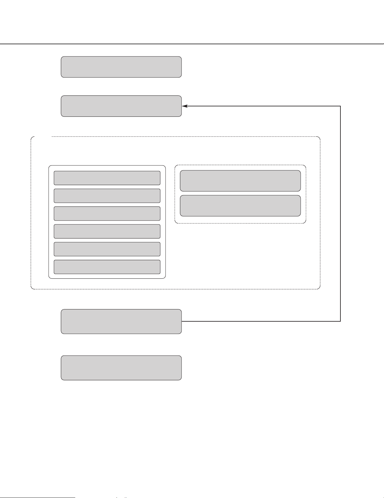
Operations flow
Startup of the operation software
z Refer to the "Start/exit the operation software" sec-
tion (☞ page 12) for how to start the operation software.
x Log in to the software.
➜➜
Login*
* For frequent users, it is unnecessary to log in at
startup of the software when using the auto login
function.
Only an administrator can configure the settings for
the auto login function.
z
x
Monitoring of live images
Searching for recorded images
Playback of recorded images
Saving of recorded images
Printing of images
Alarm/error notification
➜➜
Live window
Map window
Logout
Exit the operation software
c The operation window will be displayed. Searching,
playback and saving of the displayed image are
available using the menu panel and the tool bar.
Refer to the "Operation window" section (☞ page
17) for further information.
v Log out of the software when finishing operation.
It is possible to log in to the software again using
another user name (user switch).
Refer to the "User switch" section (☞ page 16) for
further information.
b Exit from the operation software.
Operation window When using the multi-monitor function
c
v
b
User switch
v
Page 12
12
Start/exit the operation software
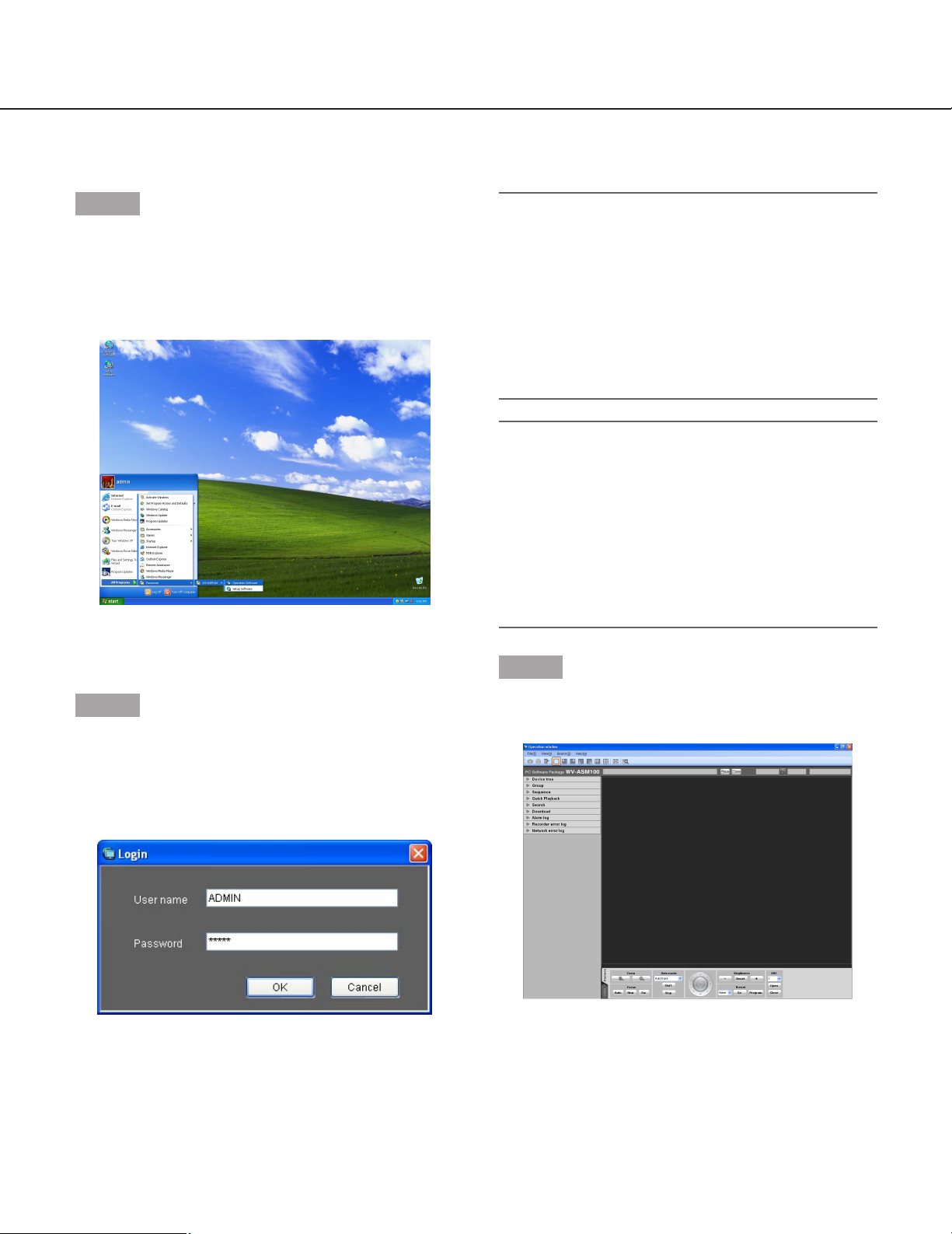
Start the operation software
Step 1
Select "Operation Software" from "start" menu ("start" "All Programs" - "Panasonic" - "WV-ASM100" "Operation Software") or double-click the "Operation
Software" icon on the desktop to launch the operation
software.
→ The login window will be displayed after the startup
splash image is displayed.
Step 2
Enter the registered user name and password.
Only an administrator is registered when operating the
software just after the installation.
Enter "ADMIN" for "User name" and "12345" for
"Password" respectively.
Important:
• It is necessary to close the setup software to start
the operation software.
The operation software will not start unless the
setup software is closed.
• To enhance the security, change the password for
an administrator before running the software.
• It is recommended to change the password for the
administrator periodically. Refer to the descriptions
for how to change the password (☞ page 15).
Note:
It is possible to register a user as the auto login
user when the same user name is used each time
to log in to the software. The default setting of
"User authentication" for each registered user is
"ON" (required the user name and password
entries). Only an administrator can configure the
setting of "User authentication" on the setup software. Refer to the setup instructions (PDF) for further information.
Step 3
Click the [OK] button.
→ The operation window will be displayed.
When a message window is displayed by clicking the
[OK] button, refer to the "Displayed messages and
solutions" section (☞ page 82) and follow the instructions.
Page 13
13
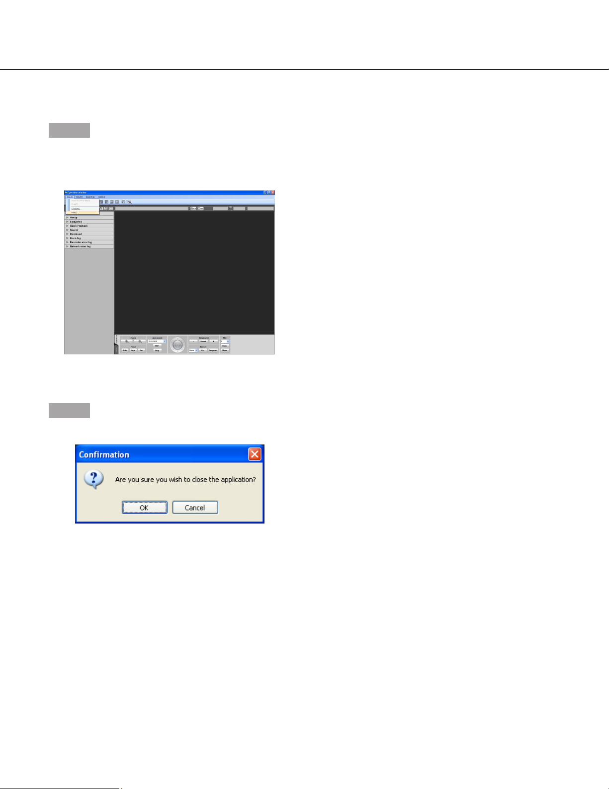
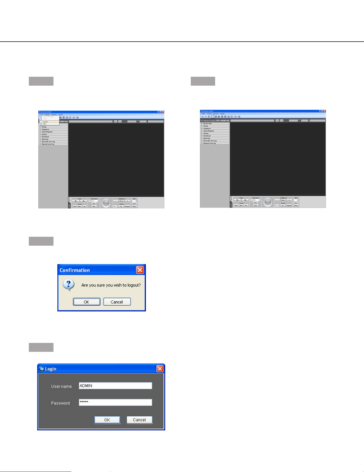
Exit the operation software
Step 1
Select "Exit(X)..." from "File(F)" on the menu bar or
click the [×] button at the top right of the operation window.
→ The confirmation window will be displayed.
Step 2
Click the [OK] button.
→ The operation software will be closed.
Page 14

14
Two types of users, the administrator and the registered users, can be managed with this software.
Only an administrator can configure the settings of this software. When a registered user logged in to the software,
only the available menus will be displayed according to the user level setting of this registered user. Only an administrator can configure the user level setting of the registered users. Refer to the setup instructions (PDF) for how to
configure the user level setting.
Important:
When using this software, use the user authentication function of this software to manage users even though the
recorders also have the user authentication function.
About the user level setting
It is possible to assign the user level to each user to restrict their operable functions. This software can assign one of
five user levels (LV1 – LV5) to every user. When "LV1" is assigned to a user, this user can operate all functions of
the software except configurations. An administrator can determine the operable functions for each user by assigning the user level "LV2" – "LV5".
The following functions can be restricted according to the user levels.
Default:
Function
Display the current settings
Alarm reset/error reset
Print/Save as JPEG file
Download
Manual recording
Recorder control
Preset position registration
Camera control
Display the alarm log
Display the recorder error log
Display the network error log
LV1
b
b
b
b
b
b
b
b
b
b
b
b
b
b
b
b
b
b
b
b
b
b
b
b
b
b
b
b
b
LV2 LV3 LV4 LV5
––––
b
User management
Page 15
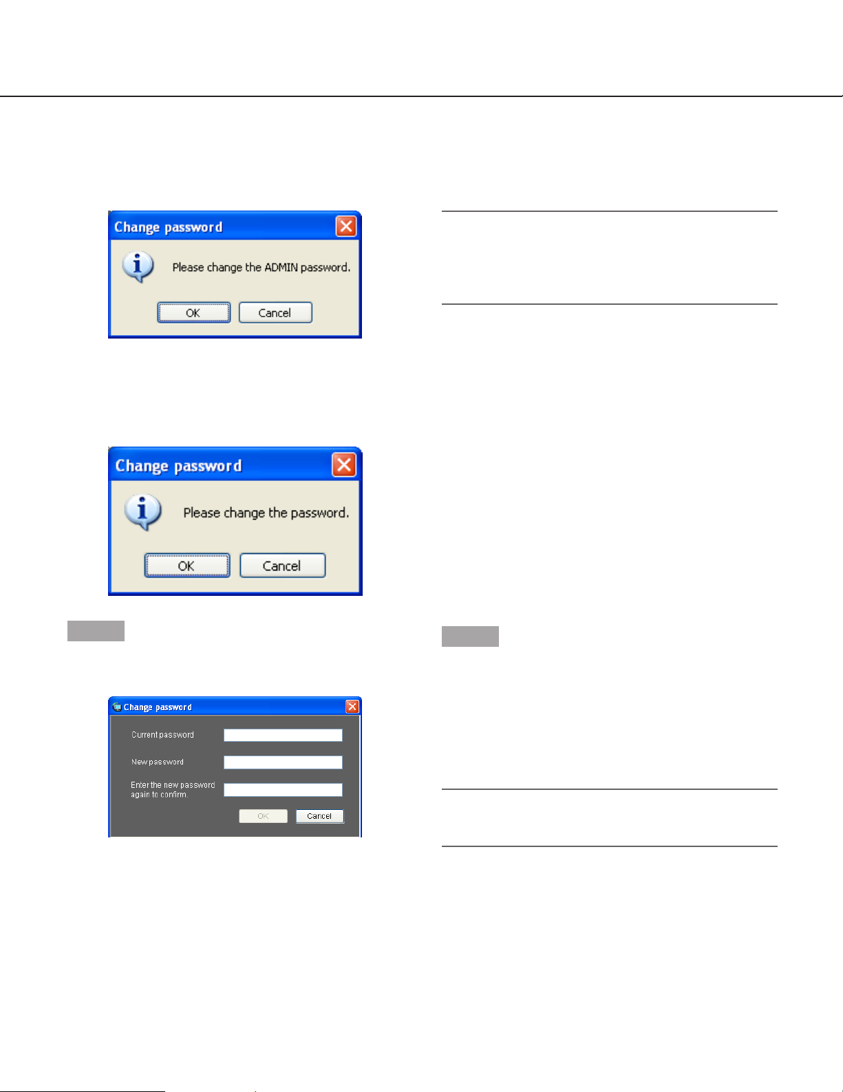
Change the password
To enhance the security, change the password when
this message window is displayed.
Step 1
Click the [OK] button on the message window.
→ The "Change password" window will be displayed.
■ Current password
Enter the current password.
The entered password will be displayed as "*".
■ New password
Enter the new password. The entered password will be
displayed as "*".
Enter up to 4 - 8 alphanumeric characters.
■ Enter the new password again to confirm.
Enter the new password again. Make sure that the
same password is entered.
The entered password will be displayed as "*".
■ [OK] button
Click this button to apply and save the new password.
(The window will close.) The [OK] button cannot be
clicked unless all entries are completed.
■ [Cancel] button
Click this button to cancel the entries. (The window will
close.)
Step 2
Complete all of the entry fields on the "Change password" window, and then click the [OK] button.
→ The new password will be applied and saved.
When a message window is displayed by clicking
the [OK] button, refer to the "Displayed messages
and solutions" section (☞ page 82) and follow the
instructions.
Important:
Refer to the setup instructions (PDF) for how to
change the password of the administrator.
15
Password's validation period
The password’s validation period can be determined (31 days/92 days/184 days) by an administrator.
When trying to log in after the set period passed, the message window saying "Change password" will be displayed.
Note:
Even when the validation period has passed, the
password will be authorized. However, this message window will be displayed each time the user
tries to log in.
Page 16
16
User switch
It is possible to switch users.
Step 1
Select "Logout(L)..." under "File(F)" on the menu bar or
double-click the [Logout] icon on the tool bar.
→ The confirmation window will be displayed.
Step 2
Click the [OK] button.
→ The "Login" window will be displayed.
Step 3
Enter the registered user name and password.
Step 4
Click the [OK] button.
→ The operation window will be displayed.
When a message window is displayed by clicking
the [OK] button, refer to the "Displayed messages
and solutions" section (☞ page 82) and follow the
instructions.
Page 17
17
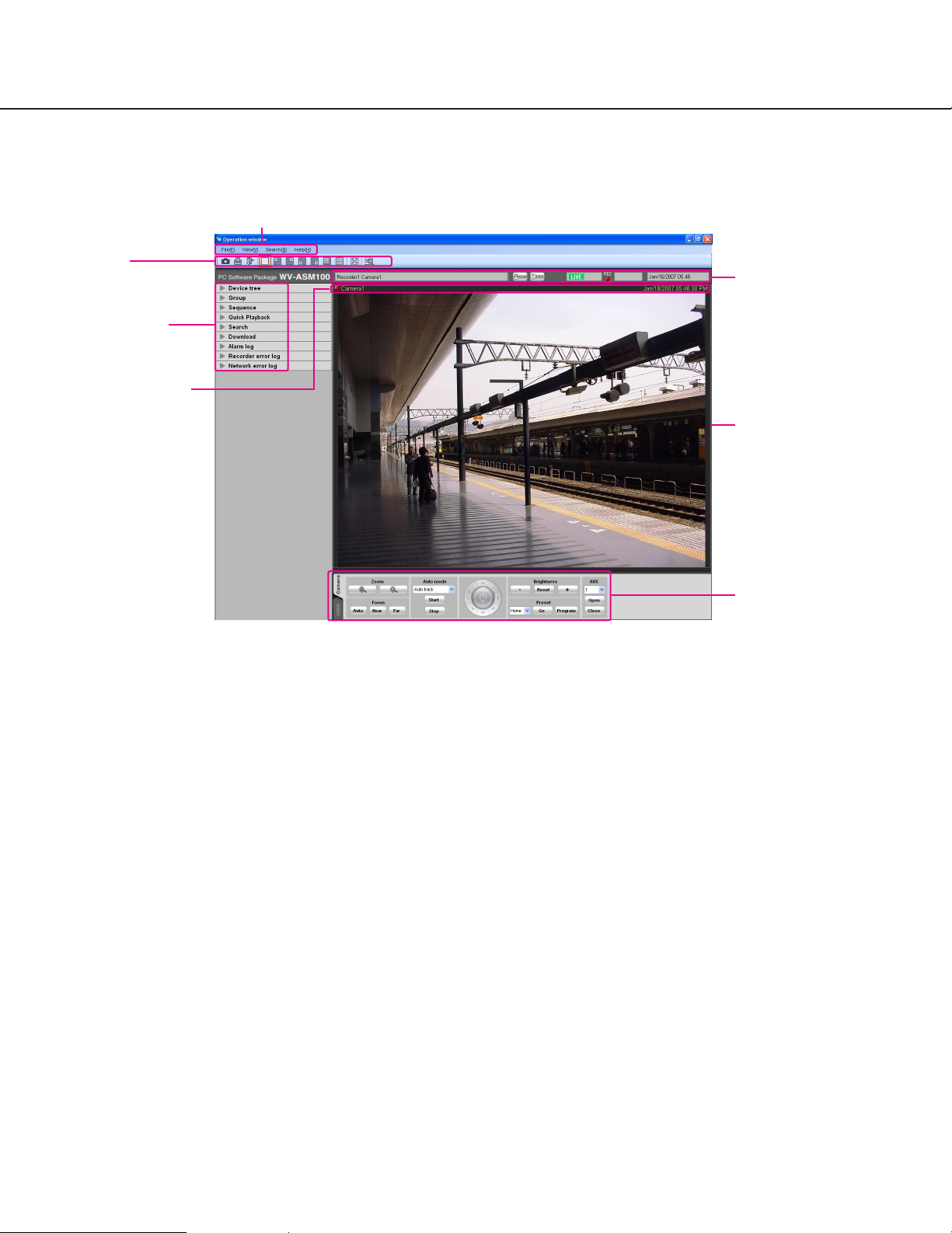
Operation window
The operation window will be displayed when logged in to the operation software. The following are descriptions
about each item displayed on the operation window.
■ Menu bar
The menu items are located on the menu bar. Refer to
the descriptions about the menu bar (☞ page 18) for
further information.
■ Tool bar
The shortcut icons of the menu items are located on
the tool bar. Refer to the descriptions about the tool
bar (☞ page 18) for further information.
■ Status bar
The following statuses will be displayed on the status
bar.
• Display status (live/playback/SD memory data) of
the images currently being displayed
• Playback speed of the images currently being
played
• Recorder title/camera title
• Recorder status (recording/copying/deleting of
data)
• Alarm occurrence/error occurrence
• Presence or absence of SD memory data in the SD
memory card of the camera
• Time and date
Refer to the descriptions about the status bar (☞ page
19) for further information.
■ Function panel
The function panel is provided on the left of the operation window. When the desired function bar on the
function panel is clicked, the respective function panel
will be displayed. Refer to the descriptions about the
function panel (☞ page 21) for further information.
■ Image display area
Images will be displayed on the selected screen type
(1/4/9/16-screen). The screen type can be changed
simply by clicking the shortcut icons on the tool bar.
When right-clicking on this area, the pop-up menu will
be displayed. (Selection from the displayed pop-up
menu is available only when right-clicking on a 1screen.) Refer to the descriptions about the pop-up
menu (☞ page 24) for further information.
The descriptions of the alarm/error will be displayed in
a pop-up window (notification window) on the operation window upon an alarm/error occurrence. Refer to
the descriptions about the alarm/error notification window (☞ page 68) for further information.
Menu bar
Tool bar
Function panel
Information display
area
Status bar
Image display area
Operation panel
Page 18
18
■ Information display area
Information of the images currently displayed, such as
time and date, camera title and the recording status,
will be displayed in this area.
Refer to the "Information display area" section (☞ page
24) for further information.
■ Operation panel
The cameras and recorders are operable with this
panel. Refer to the description about the camera operation panel (☞ page 27) and about the playback operation panel (☞ page 25) for further information.
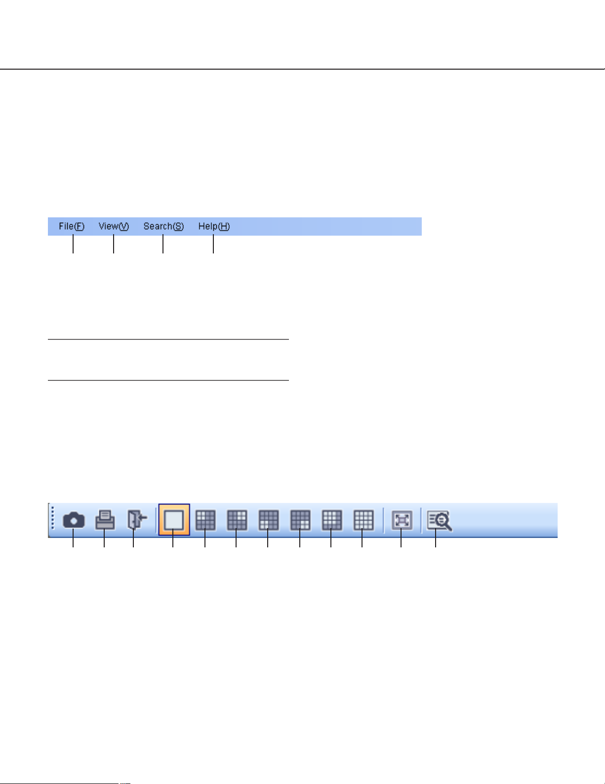
Menu bar
Tool bar
q File(F)
Contains the following menus; "Save as JPEG file",
"Print", "Logout" and "Exit".
Note:
"Save as JPEG file" and "Print" are also available
from the pop-up menu displayed by right-clicking.
w View(V)
Contains the following menus; "Function panel",
"Operation panel", "Camera/time & date", "Number
of area", "Full screen", "Live window" and "Map
window".
e Search(S)
Contains the shortcut menu to open the "Search"
window.
r Help(H)
Contains "Version information".
q [Save as JPEG file] icon
Click this icon to save the image currently being
displayed as a JPEG file.
w [Print] icon
Click this icon to print the image currently being
displayed.
e [Logout] icon
Click this icon to log out of the software. The login
window will be displayed when this icon is clicked.
r [1] icon
Click this icon to display images on a 1-screen.
t [4A] icon
Click this icon to display images using 4 areas at
the upper left of a 16-screen.
y [4B] icon
Click this icon to display images using 4 areas at
the upper right of a 16-screen.
q
w e r
q w e r t y u i o !0 !1 !2
Page 19
19
u [4C] icon
Click this icon to display images using 4 areas at
the lower left of a 16-screen.
i [4D] icon
Click this icon to display images using 4 areas at
the lower right of a 16-screen.
o [9] icon
Click this icon to display images using 9 areas at
the upper left of a 16-screen.
!0 [16] icon
Click this icon to make the image display area into
a 16-screen.
!1 [Full screen] icon
Click this icon to display the image currently being
displayed on a full screen.
!2 [Search] icon
Click this icon to display the "Search" window.
Refer to the descriptions about the "Search" window (☞ page 29) for further information.
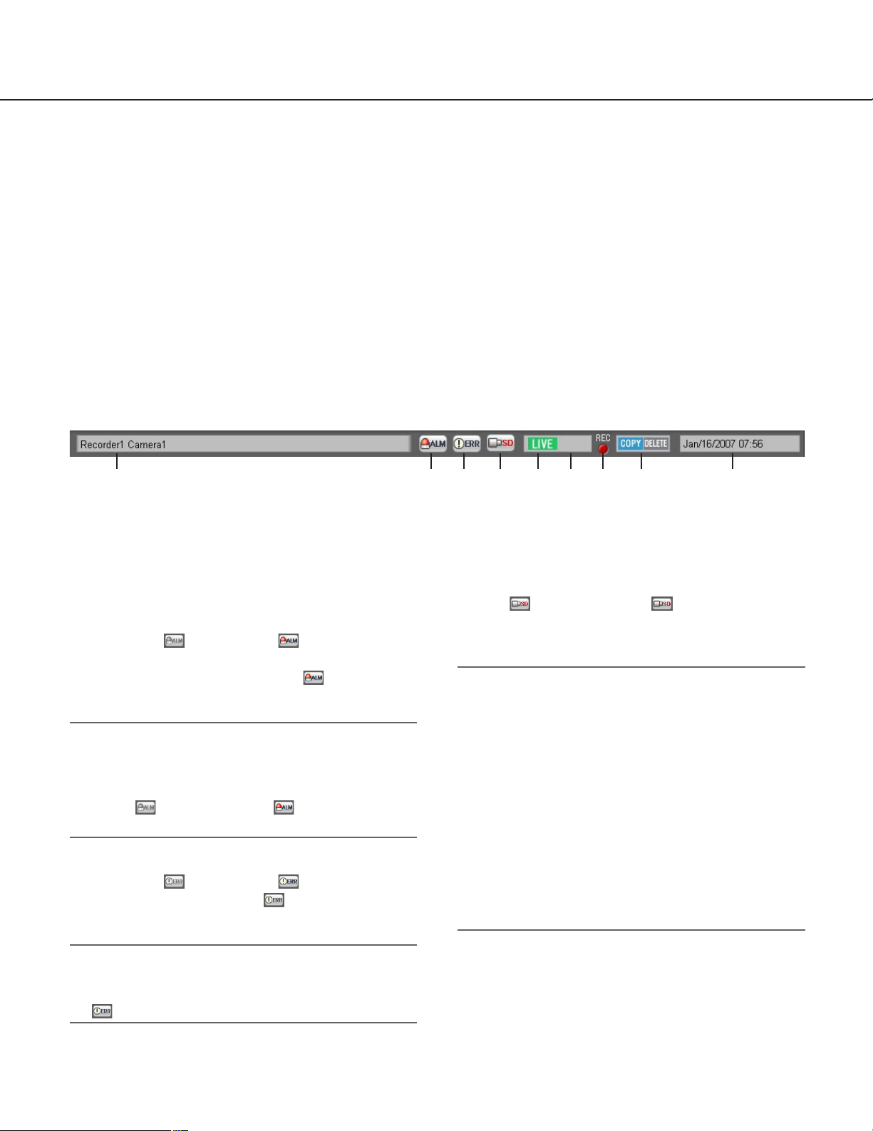
Status bar
q Recorder title/camera title
Source (recorder title and the camera title) of the
image currently being displayed will be displayed in
this area.
w [ALM] button
The button will change to when the emergency recording is being performed or when an
alarm occurred. When the button is clicked, the
alarm action will be canceled.
Notes:
• When the recorder in use is the WJ-ND300, the
error action also will be canceled.
• When the recorder in use is the WJ-ND300, the
button will not change to even when the
emergency recording is being performed.
e [ERR] button
The button will change to when an error
occurred. When the button is clicked, the error
action will be canceled.
Note:
When the recorder in use is the WJ-ND300, the
alarm action also will be canceled when the button
is clicked.
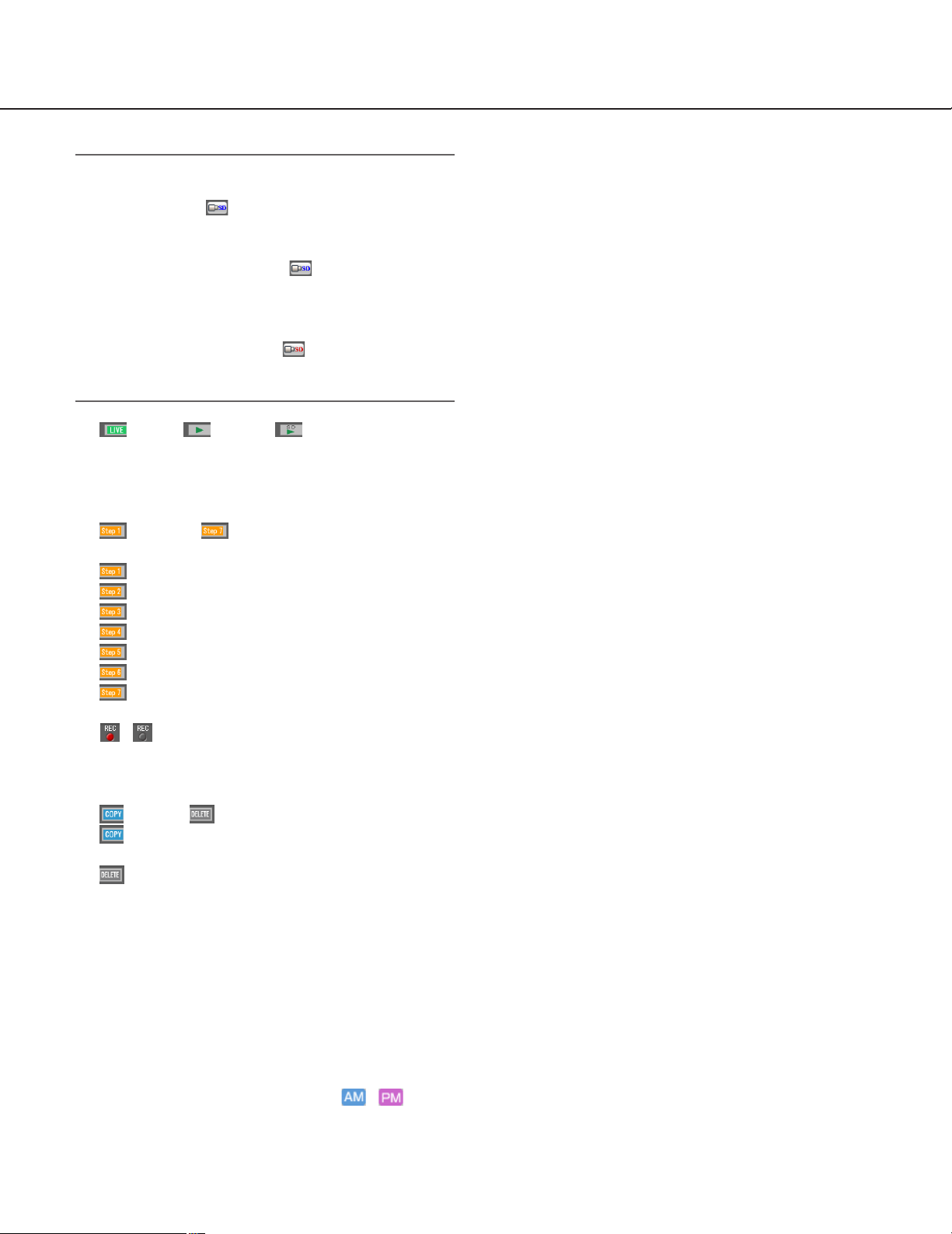
r [SD] button
When the SD memory card in the camera connected to the recorder contains recorded images, the
letters "SD" on the [SD] button will be displayed in
red ( ). When the button is clicked, the
recorded images on the SD memory card will be
transferred to the recorder.
Important:
• When the recording rate for the SD memory
recording is not set, the SD memory data obtain
button will not be displayed. Refer to the operating
instructions of the recorder in use for how to set the
recording rate for the SD memory recording.
• The SD memory data cannot be obtained during
the emergency recording. Refer to the operating
instructions of the recorder in use for further information about the emergency recording.
• All login users will be forcibly logged out and
recording of images from all cameras currently
being performed will stop when obtainment of the
SD memory data starts.
q w e r t y u i o
Page 20
20
Notes:
• The letters "SD" on the [SD] button will be displayed in blue ( ) when there is no recorded
image in the SD memory card.
• When the [SD] button is clicked while the letters
"SD" are displayed in blue ( ), this software will
check the presence of recorded image on the SD
memory card.
• When the [SD] button is clicked while the letters
"SD" are displayed in red ( ), recorded images
on the SD memory card will be transferred to the
recorder (SD memory data).
t [LIVE]/ [PLAY]/ [SD PLAY]
The type (live/playback/SD memory data playback)
of the images currently being displayed will be indicated.
y [Step 1] - [Step 7]
Indicates the playback speed.
[Step 1]: Normal playback speed
[Step 2]: Approx. 4x playback speed
[Step 3]: Approx. 8x playback speed
[Step 4]: Approx. 16x playback speed
[Step 5]: Approx. 32x playback speed
[Step 6]: Approx. 48x playback speed
[Step 7]: Approx. 96x playback speed
u / [REC] indicator
This indicator will light red when the recording of
the images currently selected is being performed.
i [COPY]/ [DELETE]
[COPY]: Indicates that copying of image data is
being performed.
[DELETE]: Indicates that deletion of image
data is being performed.
o Time and date
When displaying live images, the time and date of
the selected recorder will be displayed. Time and
date will no be displayed when images are being
displayed directly from the camera.
When displaying recorded images, the recording
time and date will be displayed.
When "24h" is selected for "Time format" (☞ setup
instructions (PDF)), the indications / will
not be displayed.
The time and date will be followed by an asterisk
"*" when the daylight saving time is applied.
Page 21
21
B
Function panel
The following are available using the function panel located at the left side of the operation window.
• Display the device tree (the icons of the connected devices in the tree view), and display images by clicking the
desired camera icon
• Group display
• Sequence display
• Quick playback
• Search
• Download
• Display the alarm log
• Display the recorder error log
• Display the network error log
When one of the function bars is clicked, the respective function panel will open. (It is impossible to open two or
more panels at the same time.)
Page 22

22
Note:
Refer to the following about the descriptions of how to operate each function panel.
"Device tree" panel Confirm the registered recorders and cameras (☞ page 35)
"Group" panel Display images from the cameras registered as a group (group display) (☞ page 39)
"Sequence" panel Display images from the cameras registered as a group sequentially (sequence dis-
play) (☞ page 40)
"Quick Playback" panel Play images using the "Quick Playback" panel (☞ page 49)
"Search" panel Play recorded images using the "Search" panel (☞ page 56)
"Download" panel Download recorded images (☞ page 57)
"Alarm log" panel "Alarm log" panel (☞ page 75)
"Recorder error log" panel "Recorder error log" panel (☞ page 76)
"Network error log" panel "Network error log" panel (☞ page 76)
Page 23
23
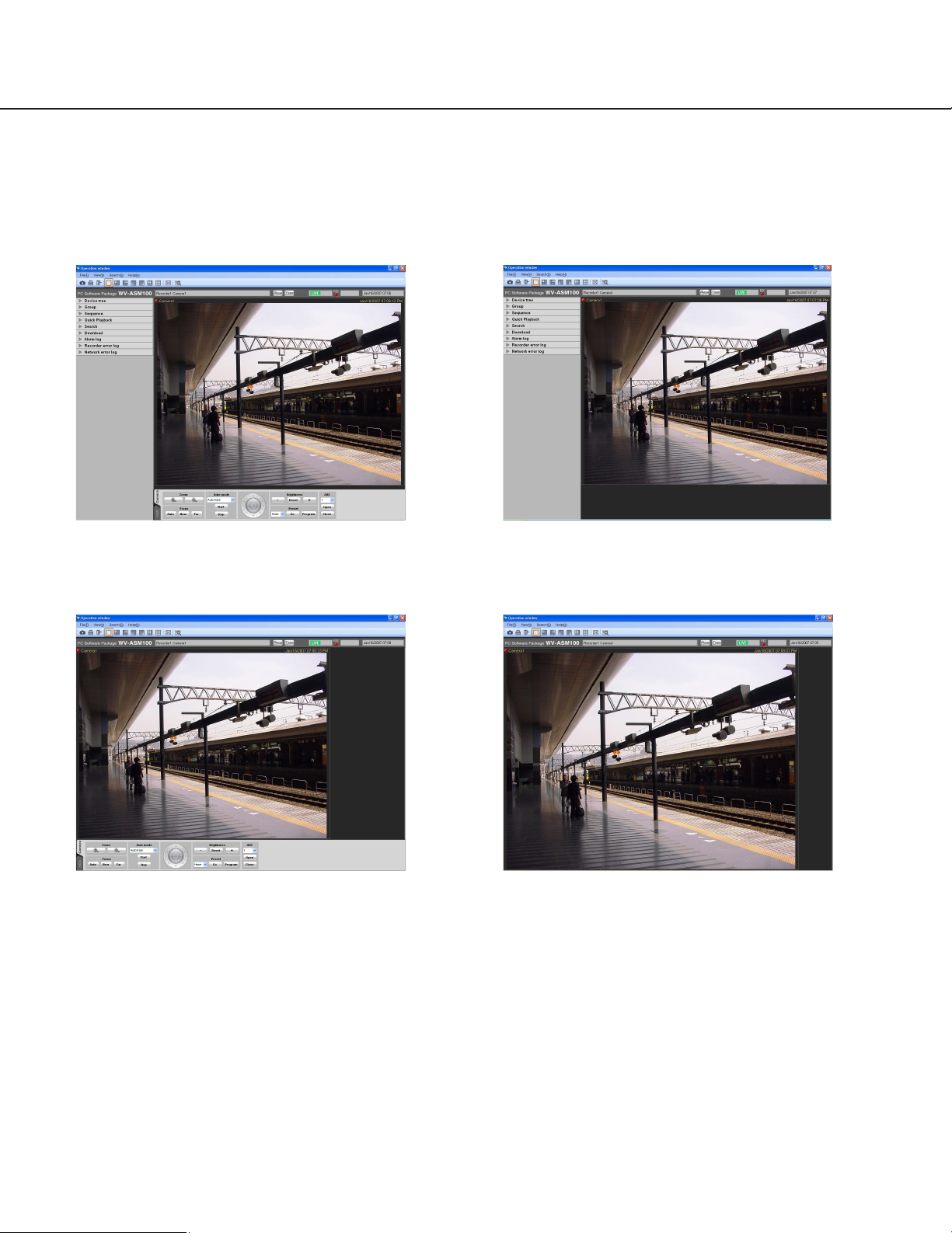
Layout of the operation window
It is possible to hide the operational panel and the function panel of the operation window as follows.
Refer to the "Menu bar" section (☞ page 18) for further information.
■ With the operation panel and the function panel ■ Without the operation panel
■ Without the function panel ■ Without the operation panel and the function
panel
Page 24
24
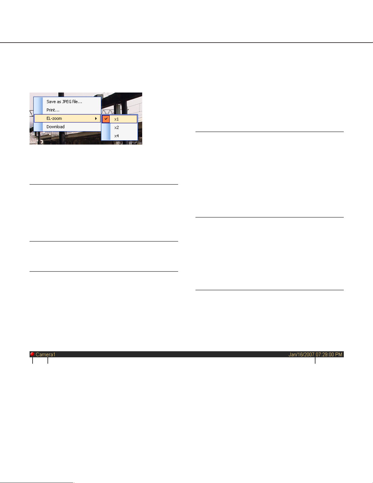
Pop-up menu
When right-clicking on the image display area, the pop-up menu will be displayed. (Selection from the displayed popup menu is available only when right-clicking on a 1-screen.)
Information display area
Information of the images currently displayed, such as time and date, camera title and the recording status, will be
displayed in this area.
q REC indicator
This indicator will light when the recording of the
images currently selected are being performed.
w Camera title
The camera title as the source of the image currently being displayed will be displayed.
e Time and date
Time and date will be displayed. Time and date will
not be displayed when images are being displayed
directly from the camera. The time and date will be
followed by an asterisk "*" when the daylight saving
time is applied.
■ Save as JPEG file…
Select this to save the image currently being displayed
as a JPEG file.
Note:
"Save as JPEG file…" on the pop-up menu will not
be displayed when the user is restricted by the user
level determined by the administrator to save an
image as a JPEG file.
Refer to the "About the user level" section (☞ page
14) for further information about the user level.
■ Print…
Select this to print the image currently being displayed.
Note:
Select this to print the image currently being displayed.
"Print…" on the pop-up menu will not be displayed
when the user is restricted by the user level determined by the administrator to print images.
Refer to the "About the user level" section (☞ page
14) for further information about the user level.
■ EL-zoom
Select this to enlarge the image currently being displayed. "x1", "x2" and "x4" are available.
■ Download
Select this to open the "Download" panel. Information
(recorder title/camera title/time and date) of the recorded image currently being played will be displayed in
the opened "Download" panel.
Notes:
• "Download" on the pop-up menu will not be displayed when the user is restricted by the user level
determined by the administrator to download
recorded images.
Refer to the "About the user level" section (☞ page
14) for further information about the user level.
• When displaying live images, it is impossible to
select "Download" on the pop-up menu.
q w e
Page 25
25
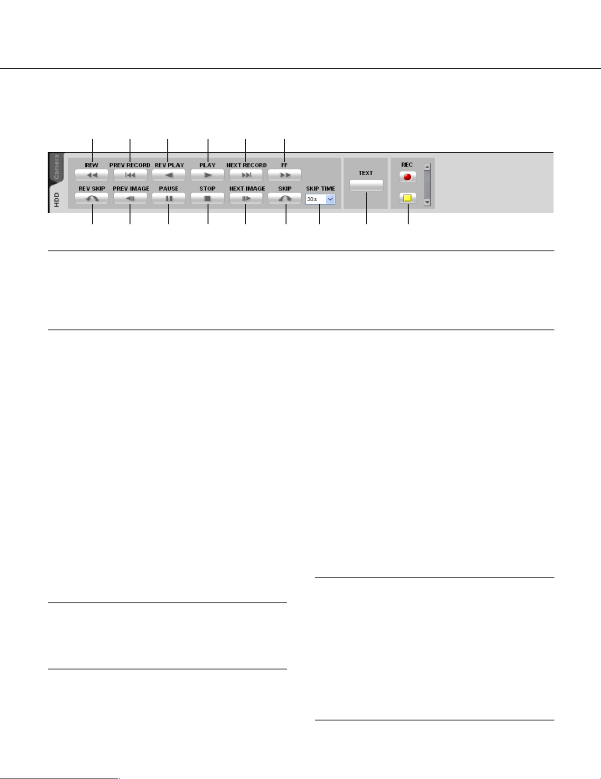
Playback operation panel
Notes:
• The playback operation panel will not be displayed when the user is restricted by the user level determined by
the administrator to play recorded images.
Refer to the "About the user level" section (☞ page 14) for further information about the user level.
• When displaying images on a multi-screen, images displayed in all areas of a multi-screen will be controlled
simultaneously using the playback operation panel.
q [REW] button
Fast reverse playback will be performed.
Playback speed for fast reverse playback will be
changed in the following order each time this button is clicked: Step2 (Approx. 4x) → Step3
(Approx. 8x) → Step4 (Approx. 16x) → Step5
(Approx. 32x) → Step6 (Approx. 48x) → Step7
(Approx. 96x)
w [PREV RECORD] button
Playback will start after skipping to the previous
recorded image.
e [REV PLAY] button
Reverse playback of a recorded image will be performed.
When this button is clicked during fast playback or
fast reverse playback, reverse playback at normal
speed will start.
Note:
When playing MPEG-4 images, some frames of
recorded images may not be displayed. Reverse
playback will be performed with the set refresh
interval of the camera.
r [PLAY] button
Playback of a recorded image will be performed.
When this button is clicked during fast playback or
fast reverse playback, playback at normal speed
will start.
t [NEXT RECORD] button
Playback will start after skipping to the next recorded image.
When this button is clicked while playing the latest
recorded image, the current playback will continue.
y [FF] button
Fast playback will be performed.
Playback speed for fast playback will be changed
in the following order each time this button is
clicked: Step2 (Approx. 4x) → Step3 (Approx. 8x)
→ Step4 (Approx. 16x) → Step5 (Approx. 32x) →
Step6 (Approx. 48x) → Step7 (Approx. 96x)
u [REV SKIP] button
Playback will start after skipping to the point of the
set amount of time backward.
Notes:
• This button will not work when the playback point is
at the start point or the end point of the recorded
images.
• This button sometimes may not work when the time
and date of the recorded images is around the time
when shifting to daylight saving time.
• When clicking this button while playing MPEG-4
images, a skipped point may be a few seconds
later from a point to be skipped with the selected
amount of time.
u
q
i
w
o
e
!0
r
!1
t
!2
y
!3 !4 !5
Page 26

26
i [PREV IMAGE] button
The previous frame will be displayed when this button is clicked during pausing.
Note:
When playing MPEG-4 images, some frames of
recorded images may not be displayed. Reverse
frame by frame playback will be performed with the
set refresh interval of the camera.
o [PAUSE] button
Playback will stop when this button is clicked during playback. Playback will resume when this button is clicked during pausing.
!0 [STOP] button
Playback will stop and live images will be displayed.
!1 [NEXT IMAGE] button
The next frame will be displayed when this button
is clicked during pausing.
!2 [SKIP] button
Playback will start after skipping to the point of the
set amount of time forward.
Note:
• This button will not work when the playback point is
at the start point or the end point of the recorded
images.
• This button sometimes may not work when the time
and date of the recorded images is around the time
when shifting to daylight saving time.
• When clicking this button while playing MPEG-4
images, a skipped point may be a few seconds
later from a point to be skipped with the selected
amount of time.
!3 SKIP TIME
Select an amount of time to skip from the following.
30s/1min/5min/10min/30min/60min
!4 [TEXT] button
When playing recorded images on a 1-screen, text
information can be added. The "Edit text" window
will be displayed when this button is clicked during
pausing playback. Refer to page 62 for further
information about the "Edit text" window.
!5 [REC START]/[REC STOP] button
Manual recording will start or stop.
Page 27
27
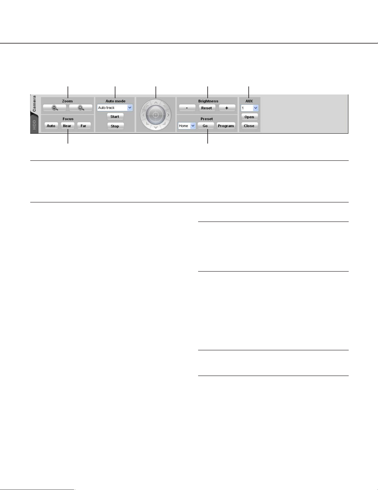
Camera operation panel
w y
q e r t u
Notes:
• Operation of the camera operation panel works only for the camera respective the selected image.
• The camera operation panel will not be displayed when the user is restricted by the user level determined by the
administrator to operate the cameras.
Refer to the "About the user level" section (☞ page 14) for further information about the user level.
q Zoom
Zooming can be adjusted by clicking the [-] (wide)
button or the [+] (tele) button.
w Focus
The auto focus function can be performed by clicking the [Auto] button.
Focusing can be manually adjusted by clicking the
[Near] button or the [Far] button.
e Auto mode
Select the auto function from the following.
Auto track: The camera automatically tracks
motion of the subject displayed in the image
display area.
Auto pan: The camera automatically moves from
the start point to the end point set in advance.
Preset sequence: The camera automatically
moves to the preset positions in numerical
order of the preset position numbers.
Sort: The camera automatically moves to the clos-
est preset position from the current position.
Patrol: The camera automatically traces the route
set in advance.
When the [Start] button is clicked, the selected
auto function will start.
When the [Stop] button is clicked, the selected auto
function will stop.
Note:
The auto functions are available only when the
camera in use has these functions. Refer to the
operating instructions of the camera in use for further information about the auto function of the camera.
r Control pad
Clicking the buttons around the control pad can
move (pan/tilt) a camera in the clicked direction.
Clicking inside the control pad also can adjust the
vertical/horizontal position (pan/tilt) of the displayed
live images. Panning/tilting speed will be faster if a
clicked point gets farther from the center point of
the control pad.
Note:
Panning and tilting are available only when the
camera in use is a PTZ camera.
t Brightness
Brightness can be adjusted by clicking the [–]
(darker) button or the [+] (brighter) button.
It is possible to reset the set brightness by clicking
the [Reset] button.
Page 28

28
y Preset
Select a preset number from the following.
Home/1 - 256
Click the [Go] button after selecting a preset number. The camera will move to the selected preset
position.
When the [Program] button is clicked after selecting a preset number, the current position will be
registered as the preset position of the selected
preset position number.
Notes:
• Preset position function is available only when the
camera in use is a PTZ camera.
• It is impossible to register a position when "Home"
is selected for the preset position number.
• It is possible to register the preset position only
when the user is not restricted by the user level
determined by the administrator to operate the
cameras.
Refer to the "About the user level" section (☞ page
14) for further information about the user level.
• Refer to the operating instructions of the recorder
and the camera in use for further information about
the available preset position numbers.
u AUX
Select an AUX OUT connector from the following.
1/2/3
When the [Open] button is clicked, the selected
AUX OUT connector will be opened.
When the [Close] button is clicked, the selected
AUX OUT connector will be closed.
Page 29

29
Search window
When "Search(S)..." under "Search(S)" on the menu bar is selected or the [Search] icon on the tool bar is clicked,
another window will open and the "Search" window will be displayed. Search desired recorded images on the
recorder by designating the search conditions on the "Search" window.
■ Search by
Select the search target from the following.
Recorder: Select recorders to be searched. When
"Recorder" is selected, the recorders will be displayed in the tree view. Select the recorders and
the cameras to be searched by checking the
checkbox.
Group: Select groups to be searched. When "Group"
is selected, the group list will be displayed. Select
the groups to be searched by checking the checkbox.
Map: Select maps to be searched. When "Map" is
selected, the map list will be displayed. Select the
maps to be searched by checking the checkbox.
■ REC event
Select the recording event type to be searched.
Manual: Select to search for images recorded by man-
ual recording.
Schedule: Select to search for images recorded by
the schedule recording.
Emergency: Select to search for images recorded by
the emergency recording.
Site alarm: Select to search for images recorded upon
the site alarm occurrence.
Terminal alarm: Select to search for images recorded
upon the terminal alarm occurrence.
Command alarm: Select to search for images record-
ed upon the command alarm occurrence.
SD memory: Select to search for the SD memory
data.
Note:
Only "SD memory" is unavailable to select together
with other recording event types. To search for the
SD memory data, select "SD memory" alone.
■ Text
It is possible to search for recorded images only with
or without text information.
Select "Added" or "None".
When"--" is selected, images will be searched regardless of with or without text information.
■ Start
Select the start time between "Jan/01/2005" and
"Dec/31/2034". Select a number for hour from "AM12"
- "PM11". Select a number for minute from "00" - "59".
■ End
Select the end time between "Jan/01/2005" and
"Dec/31/2034". Select a number for hour from "AM12"
- "PM11". Select a number for minute from "00" - "59".
Note:
When the software in use is European specification, select the start time and the end time from the
following.
Date: Between "01/01/2005" and "31/12/2034"
Hour: Between "0" and "23"
Minute: Between "00" and "59" (1 minute step)
■ [OK] button
Click this button to start searching.
■ [Cancel] button
Click this button to cancel the edited search conditions
and close the "Search" window.
■ Search result number
Search result number will be displayed.
Page 30

30
■ Search result list
Search result will be displayed in list form. When a
result is clicked, the "Search" window will close and
the selected image will be displayed on a 1-screen.
When playback of the selected result starts, the
descriptions of the selected result will be displayed in
the search panel of the operation window.
Note:
No image will be displayed when search result
number is "0".
Alarm/error notification
A pop-up window (notification window) will be displayed when an alarm or an error occurred.
■ Alarm notification
Notifies of an alarm occurrence.
■ Error notification
Notifies of a recorder error occurrence or a network
error occurrence.
Version window
When selecting "Version information" under "Help(H)" on the menu bar, version of this software will be displayed.
Page 31

31
Outline of the multi-monitor function
The multi-monitor function using up to three PC monitors is available, and it makes possible to display the operation
window, the live window and map window simultaneously.
Important:
To user the multi-monitor function, it is necessary to install an additional video card on the PC in use. Refer to the
setup instructions (PDF) for further information about the video card compatible with this software.
Note:
Availability of the live window can be determined on the setup software. Refer to the setup instructions (PDF) for
further information.
The following are the examples when using the multi-monitor function.
■ 1 PC monitor (Not use the live window)
■ 2 PC monitors (Use the live window)
■ 3 PC monitors (Use the live window)
When using a single PC monitor, it is recommended to
select "Not use" for "Live window" and to operate this
software with the operation window and the map window.
<When using two PC monitors>
Select "Use" for "Live window".
Operation while displaying the operation window and
the map window on one of the two PC monitors and
the live window on the other PC monitor is suitable.
* When "Use" is selected for "Live window", images
can be displayed only on a 1-screen or on a 4screen on the operation window.
<When using three PC monitors>
Select "Use" for "Live window".
Operation while displaying the operation window, the live window and
the map window on each of three
PC monitors is suitable.
* When "Use" is selected for "Live
window", images can be displayed only on a 1-screen or on
a 4-screen on the operation window.
Page 32

32
Live window
The following are descriptions about each item displayed on the live window.
■ Group information display area
Status of the sequence and the group title will be displayed. Refer to the following section of "Group information display area" for further information.
■ Camera information display area
Status of recording, alarm occurrence and the camera title will be displayed. Refer to the following section of
"Camera information display area" for further information.
■ Live image display area
Live images by the group display or the sequence display will be displayed. It is also possible to automatically display live images from the camera in which an alarm occurred. Refer to the setup instructions (PDF) for how to configure the setting.
Group information display area
Note:
When the setting is configured to automatically display live images from the camera in which an alarm occurred,
the group information display area will not be displayed while displaying live images from this camera.
■ [SEQ]
Indicates that the sequence display is being performed currently. When the sequence display is being performed,
the indication will be displayed. When the sequence display is being paused, the indication will be displayed. This indication will not be displayed when the group display is being performed.
■ Group title
The group title will be displayed.
Group information
display area
Live image display area
Camera information display
area
Page 33

33
Camera information display area
Pop-up menu
When right-clicking on the image display area, the pop-up menu will be displayed. There are two types of the pop-up
menus as follows.
■ Group
Select a group to be displayed in the live image display
area from the submenu.
■ Sequence
Select a sequence to be displayed in the live image
display area from the submenu.
■ Pause sequence/Resume sequence
Select to pause or resume the sequence display.
"Pause sequence" is available during the sequence
display and "Resume sequence" is available during
pausing the sequence display. These menus will not
be displayed when the group display is being performed.
■ Display
It is possible to display/hide the group information display area and the camera information display area by
selecting "Group title" or "Camera title" from the submenu.
■ Alarm mode reset
The alarm status will be reset.
■ Full screen
The live window will be displayed on a full screen.
During the group display or the
sequence display
During the live image display at an
alarm occurrence
q
w e
q REC indicator/alarm indicator
This indicator will light when the recording of the
images currently being displayed is being performed. When the setting is configured to automatically display live images from the camera in which
an alarm occurred, the REC indicator will turn to
the alarm indicator .
w Camera title
The camera title will be displayed.
e Time and date
Time and date will be displayed. When this software is configured to display live images directly
from the camera in which an alarm occurred at an
alarm occurrence, descriptions of the alarm will be
displayed instead of time and date. The time and
date will be followed by an asterisk "*" when the
daylight saving time is applied.
Page 34

34
Map window
The following are descriptions about each item displayed on the map window.
■ Map selection
Select a map.
■ Map display area
The selected map will be displayed. The camera icons and the map icons will be displayed on the map.
Map selection
Map display area
Page 35

35
Monitor live images
Live images from up to 16 cameras can be displayed simultaneously on this software. It is not only possible to display live images from cameras connected to the same recorder, but also from cameras connected to different
recorders. It is also possible to display live images directly from the cameras, not through the recorder.
Important:
• Refer to the setup instructions (PDF) about the models and the versions of the recorders and the cameras to be
used to display live images directly from the camera.
• Time and date will not be displayed on the status bar and the information display area when displaying images
directly from the camera, not through the recorder.
Notes:
• Speed of image load may become slow when the processing load is too heavy on the recorder or on the PC
(such when many cameras are connected, when displaying live images from many cameras, etc.) or when the
network traffic is heavy.
• When using the live window, images from up to 20 cameras (16 cameras on the live window and 4 cameras on
the operation window) can be displayed simultaneously. Refer to the "Operate using the multi-monitor function"
section for further information (☞ page 44).
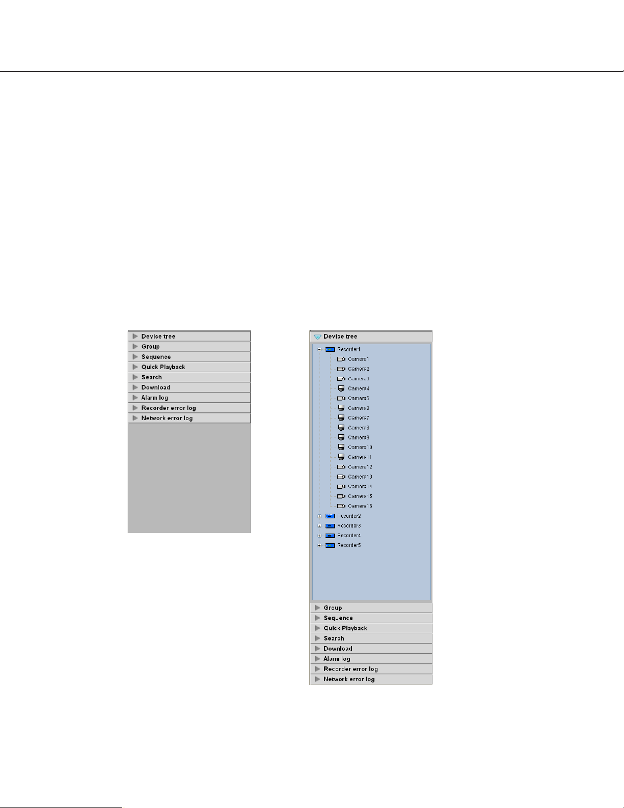
Confirm the registered recorders and cameras
The recorders and cameras registered in this software can be confirmed as follows.
Step 1
Click the "Device tree" bar on the function panel.
→ The "Device tree" panel will be displayed. The reg-
istered recorders will be displayed in the tree view.
Only an administrator can register recorders.
Refer to the setup instructions (PDF) for further
information.
Page 36

Icon
36
Step 2
Double-click the recorder icon or click the [+] mark next
to the recorder icon.
→ The icons of the cameras registered in the recorder
will be displayed.
Icons in the device tree
The following are the descriptions of the icons displayed in the device tree.
*1 Sometimes, live images may not be displayed even when the camera icon indicates that it is online. In this case,
the following are possible causes.
• The Panasonic alarm protocol notification function is not active on the recorder and/or this software.
• The recorder is currently being configured using "HDD DISK MENU", or the SD memory recording is being
performed.
Description
PTZ camera (online)*
1
WJ-ND300 (online)
WJ-ND200 (online)
Fixed camera (online)*
1
(offline)
(offline)
When the icon / is clicked, the icon will turn to / .
Page 37

37
Monitor images from the selected camera
Click the desired camera icon. Images from the selected camera will be displayed. Images from the camera can be
displayed in various ways; display on a 1-screen, display in the desired area, display on a full screen, etc.
Monitor images on a 1-screen
Step 1
Click the desired camera icon when the image display
area is 1-screen.
→ Images from the selected camera will be displayed
on a 1-screen.
Note:
When right-clicking on the displayed image, the
pop-up menu will be displayed. "Save as JPEG
file…", "Print..." and "EL-zoom" are available from
the displayed pop-up menu.
Specify the area to display images
Step 1
Click the desired area when displaying images on a
multi-screen (4/9/16).
→ The frame will be displayed around the selected
area to indicate the current selection.
Step 2
Click the desired camera icon.
→ Image from the selected camera will be displayed
in the selected area.
Page 38

38
Monitor images on a full screen
Step 1
Display live images.
→ Refer to the "Monitor live images" section (☞ page
35) for how to display live images.
Note:
It is also possible to display recorded images on a
full screen. Playback on a full screen is available
only at normal playback speed (1x) and reverse
playback is unavailable.
Step 2
Select "Full screen(F)" under "View(V)" on the menu
bar or click the [Full screen] icon on the tool bar.
→ The image display area with the information display
area will be displayed on a full screen.
Step 3
Full screen display will be canceled and will return to
the normal window size by selecting "Exit from the full
screen display" from the pop-up menu displayed by
right-clicking on the image displayed on a full screen.
Page 39

39
Display images from the cameras registered as a group (group display)
It is possible to register multiple cameras as a group. When registering multiple groups, images from the cameras
can be displayed in group of the cameras.
Step 1
Click the "Group" bar on the function panel.
→ The "Group" panel will be displayed.
The name of the registered group and the group
icon that indicates the selected multi-screen will be
displayed.
■ Group list
The registered groups will be displayed in list form.
Only groups available for the login user will be displayed. Only an administrator can register the cameras
as groups. Refer to the setup instructions (PDF) for
further information.
■ Group title
The group title will be displayed with the icon that indicates the screen pattern selected to display the
respective group.
When clicking the icon, images from the selected
group will be displayed in the image display area with
the selected screen pattern.
The icon indicates the screen pattern as follows.
1-screen icon
4-screen icon
9-screen icon
16-screen icon
Step 2
Click the desired group icon.
→ Images of the selected group will be displayed on
the registered multi-screen.
Page 40

40
Display images from the cameras registered as a group sequentially (sequence display)
Images from the groups registered to display on a 1-screen or 4-screen can be sequentially displayed on a full
screen. It is possible to set the dwell time (sequence interval) for the sequence display.
Notes:
• Actual dwell time may become longer than the set dwell time when the processing load is too heavy on the
recorder or on the PC (such when many cameras are connected, when displaying live images from many cameras, etc.) or when the network traffic is heavy.
• Images sometimes may not be displayed during the sequence display depending on the network environment.
• It is recommended to use less than 10 recorders when using the sequence display.
Step 1
Click the "Sequence" bar on the function panel.
→ The "Sequence" panel will be displayed.
■ Sequence
Select the registered sequence from the drop-down
list. Only an administrator can register the sequence
using the setup software.
Refer to the setup instructions (PDF) for further information.
■ Sequence dwell time
Select the dwell time of the selected sequence from
the following.
3s/5s/10s/15s/20s
Default: 3s
Note:
"Sequence dwell time" is the duration from the
moment when completing displaying of all images
from the cameras registered as a group till the
moment when starting displaying images of the
next group.
■ [Start] button
When this button is clicked, the sequence display will
start with the selected dwell time.
Page 41

41
Step 2
Click the [Start] button after selecting the registered
sequence and the sequence dwell time.
→ The window will be switched to a full screen and
the sequence display will start.
Step 3
To stop the sequence display, select "Exit from the full
screen display" from the pop-up menu displayed by
right-clicking. When the sequence display is stopped,
the full screen will return to the normal window size
and live image display will start. Live images displayed
after stopping the sequence display will be of the
group’s that have been displayed when the sequence
display is stopped.
Page 42

Submenu: 1 (O)
Tool bar:
1
1
5
9
13
2
6
10
14
3
7
11
15
4
8
12
16
42
Switch the pattern of the screen
The following are the descriptions of how to switch the pattern of the screen (1/4/9/16) in the image display area.
Step 1
Select "Number of area(S)" under "View(V)" on the
menu bar or click the desired icon ([1] - [16]) on the
tool bar.
→ The images will be displayed on the selected
screen pattern.
Switch the screen pattern from 16-screen
When the screen pattern is switched from 16-screen, images to be displayed will be as follows.
Group display on 16-screen
Group display on 16-screen
Group display on 1-screen
* Images being displayed on the selected area of 16-screen
will be displayed on a 1-screen.
Group display on 4-screen
1
2
3
4
5
6
7
8
Tool bar:
12
9
10
11
12
13
14
16
15
Submenu: 4A (A)
56
Page 43

43
Switch the screen pattern by double-clicking
When double-clicking on the desired area while displaying images on a multi-screen (4/9/16), the selected area will
be displayed on a 1-screen. When double-clicking on the image displayed on a 1-screen, the image will be displayed
on a full screen.
Group display on 16-screen Group display on 4-screen
1
34
78
5
9
13
2
6
10
14
3
7
11
15
4
8
12
16
Submenu: 4B (B)
Tool bar:
Group display on 16-screen Group display on 4-screen
1
910
13 14
5
9
13
2
6
10
14
3
7
11
15
4
8
12
16
Submenu: 4C (C)
Tool bar:
Group display on 16-screen Group display on 4-screen
1
11 12
15 16
5
9
13
2
6
10
14
3
7
11
15
4
8
12
16
Submenu: 4D (D)
Tool bar:
Group display on 16-screen Group display on 9-screen
1
5
9
13
2
6
10
14
3
123
567
91011
7
11
15
4
8
12
16
Submenu: 9 (N)
Tool bar:
Group display on 16-screen Display on a 1-screen Display on a full screen
Double-click Double-click
1
11
5
9
13
2
6
10
14
3
7
11
15
4
8
12
16
Select "Exit from the full screen display" from the right-click pop-up menu.
Page 44

44
Operate using the multi-monitor function
The multi-monitor function using up to three PC monitors is available, and it makes possible to display the operation
window, the live window and map window simultaneously.
Note:
Availability of the live window can be determined on the setup software. Refer to the setup instructions (PDF) for
further information.
Operate the operation window
On the operation window, operations relating to the live image display, playback and the sequence display are available.
Displayable number of areas in the window varies depending on the "Live window" setting.
When "Use" is selected for "Live window": 1-screen, 4-screen
When "Not use" is selected for "Live window": 1-screen, 4-screen, 9-screen, 16-screen (Only 1-screen and 4-screen
are available for the sequence display.)
Note:
A black screen sometimes may be displayed when keeping on clicking around the edge of the screen to enlarge
MPEG-4 images using the EL-zoom function.
Page 45

Operate the live window
On the live window, operations relating to the live image display of group (1-screen, 4-screen, 9-screen, 16-screen)
and the sequence display (1-screen, 4-screen) are available.
Select "Live window(L)…" under "View(V)" on the menu bar to display the live window.
Pop-up menu
The pop-up menu will be displayed when right-clicking on the live window.
■ Group
Select the desired group under "Group" from the popup menu to switch the group. Live display of the selected group will start even during the live image display or
the sequence display. Only an administrator can register the groups using the setup software. (Up to 400
groups can be registered.) Refer to the setup instructions (PDF) for further information.
■ Sequence
Select the desired sequence under "Sequence" from
the pop-up menu to switch the sequence. Live display
of the selected sequence will start even during the live
image display or the group display. Only an administrator can register the sequences using the setup software. (Up to 10 sequences can be registered.) Refer
to the setup instructions (PDF) for further information.
■ Pause sequence/Resume sequence
When "Pause sequence" is selected, the sequence
display currently being performed will be paused.
When "Resume sequence" is selected, the paused
sequence display will resume.
Note:
These menus will not be displayed when the group
display is being performed.
■ Display
The group information display area and the camera
information display area can be displayed/hidden from
the pop-up menu.
■ Full screen
The full screen display can be turned on/off from the
pop-up menu.
45
Page 46

46
Operate the map window
Step 1
Select "Map window(M)…" under "View(V)" on the
menu bar to display the map window.
→ The map window will be displayed.
Step 2
Map selection.
Select the desired map from the drop-down list.
Notes:
• When the camera icon on the map is clicked, live
images from the selected camera will be displayed
in the selected area on the operation window.
However, live images will not be displayed when
the operation window is being displayed on a full
screen.
• When the map icon on the map is clicked, the map
on the displayed on the map window will be
changed.
Icons on the map
The following are the descriptions of the icons displayed on the map.
Icon Description
Offline cameras
When the icon / is clicked, the respective camera will be online and the icon will turn
to / .
PTZ camera (online)
Fixed camera (online)
Cameras in the alarm status
The icon will blink for 10 seconds after receiving an alarm.
When the icon / is clicked, it will turn to / .
Map
Page 47

47
Operate the cameras
It is possible to operate the camera while displaying live images.
Some models may not be operable. Refer to the setup instructions (PDF) for the cameras compatible with this software.
This software can operate the following.
• Pan/tilt*1: Adjusts the horizontal/vertical position of the displayed image.
• Zoom: Zooms in/out the displayed image.
• Focus: Adjusts the focal point of the displayed image.
• Brightness: Adjusts the lens iris.
• Preset*1: Moves the camera to the preset position registered in advance. Registration of the preset
positions is also available.
• Auto mode*1: Starts the selected auto function.
• AUX: The device connected to the AUX OUT connector can be controlled by opening/closing the
AUX OUT connector.
*1 Available only for the PTZ cameras
Notes:
• Some functions may be unavailable depending on the model of the camera.
• "AUX" is unavailable when the model of the camera is NP472/NS32x/NW47x and images (JPEG) from the cam-
era are transferred via a recorder.
Step 1
Display live images.
→ Refer to the "Monitor live images" section for how
to display live images (☞ page 35). When displaying images on a multi-screen, click the desired are
to select the camera to be operated. The selected
area will be displayed with the frame in orange.
Step 2
Click the [Camera] tab.
→ The camera operation panel will be displayed.
Step 3
Operate the camera using the buttons on the camera
operation panel.
→ Refer to the "Camera operation panel" section
(☞ page 27) for further information about the buttons on the camera operation panel.
Note:
When the camera is being operated by a user
whose user level is higher, this camera is unavailable to operate until this user stops operation of
this camera.
Page 48

48
Playback
Notes:
• Speed of image load may become slow when the processing load is too heavy on the recorder or on the PC
(such when many cameras are connected, when displaying many recorded images, etc.) or when the network
traffic is heavy.
• When playing recorded images on a multi-screen, sometimes the recording time synchronization of the displayed
recorded images may not be performed.
• When there is no image recorded by the selected camera, a black screen will be displayed.
Step 1
Display live images.
→ Refer to the "Monitor live images" section (☞ page
35) for how to display live images.
Step 2
Click the [HDD] tab.
→ The playback operation panel will be displayed.
Step 3
Click the [PLAY] button.
→ Playback image will be displayed in the image dis-
play area where live images are being displayed.
The indication displayed in the information
display area will turn to the indication .
Note:
Playback will start from the latest recorded image.
Step 4
To stop playback, click the [STOP] button.
→ Live images will be displayed in the image display
area where playback images are being displayed.
The indication displayed in the information display area will turn to the indication .
Note:
Operate the playback images using the buttons on
the playback operation panel. Refer to the
"Playback operation panel" section (☞ page 25) for
further information about the buttons on the playback operation panel.
Page 49

49
Play images using the "Quick Playback" panel
Search and playback of recorded images can be easily performed when using the "Quick Playback" panel.
There are three ways to play recorded images as follows.
• Play recorded images from the search result list displayed after searching by designating the recording time
• Play recorded images from the search result list displayed after searching by designating the time and date of SD
memory data
• Play the latest recorded image
Notes:
• When displaying images on a multi-screen, playback images will be displayed in all areas.
• It is impossible to play SD memory data on a multi-screen.
• When the SD memory data contains not many frames, playback sometimes may not be performed in a normal
manner. (A black screen may be displayed, or speed of image load may become slow, etc.) In this case, display
the image with frame playback/ reverse frame playback.
Step 1
Display live images from the recorder to be searched.
→ Refer to the "Monitor live images" section (☞ page
35) for how to display live images.
Step 2
Click the "Quick Playback" bar on the function panel.
→ The "Quick Playback" panel will be displayed.
The following are descriptions about each item displayed on the "Quick Playback" panel.
■ Calendar/time
Select time and date from "Jan/01/2005" "Dec/31/2034".
Select a number for hour from "AM12" - "PM11".
Select a number for minute (5 minutes step).
Note:
When the software in use is European specification, select the time and date from the following.
Date: Between "01/01/2005" and "31/12/2034"
Hour: Between "0" and "23"
Minute: Between "00" and "55" (5 minutes step)
Page 50

50
■ SD memory
Check this checkbox to search for recorded images
from the SD memory data.
Note:
When displaying images on a multi-screen, it is
impossible to check the checkbox.
■ [Go to date] button
Click this button to start playback of images recorded
at the selected time and date.
■ [Go to last] button
Click this button to start playback of the latest recorded
images.
Step 3
Select the desired time and date.
Note:
It is unnecessary to designate the time and date
when playing the latest recorded image. The latest
recorded image to be played is determined according to the setting of the recorder. Refer to the operating instructions of the recorder in use for further
information.
Step 4
Click the [Go to date] button or the [Go to last] button.
→ Images recorded at the selected time and date or
the latest recorded image will be played in the
image displayed area.
Notes:
• When playing MPEG-4 image, playback may start
from a point several seconds after the designated
time and date. Sometimes, playback may start from
the beginning of the next record.
• When playback cannot be performed correctly
even when designating the time and date of the SD
memory data to be searched, it may be possible
that there is no image recorded by the SD memory
recording.
Page 51

51
Start/stop recording manually
Note:
Manual recording is available only when the user level of a login user is "LV1".
Step 1
Display live images from the recorder to be used for
recording.
→ Refer to the "Monitor live images" section (☞ page
35) for how to display live images.
Step 2
Click the [HDD] tab.
→ The playback operation panel will be displayed.
Step 3
Click the [D]/[C] buttons in the "REC" box.
→ The [REC START] button and the [REC STOP]
button will be displayed.
Step 4
Click the [REC START] button.
→ Recording will start and the REC indicator of the
camera channel used for recording will light red.
Step 5
To stop recording, click the [REC STOP] button.
→ The REC indicator will go off.
Note:
When another recording such as by an alarm
occurrence is being performed, the REC indicator
will not go off and only the manual recording will
stop. Refer to the operating instructions of the
recorder in use for further information about the
recording.
Page 52

52
Search and play recording event
Search for a recording event as follows.
It is possible to search for the following recording events by designating the search target; recorders, groups and
maps.
• Manual
• Schedule
• Emergency
• Site alarm
• Terminal alarm
• Command alarm
• SD memory
Notes:
• Only "SD memory" is unavailable to search together with other recording event types. To search for the SD
memory data, search for the SD memory data alone.
• Up to 1 000 search results will be displayed. When more than 1 000 search results are found, the latest 1 000
search results will be displayed in the search result list. When searching in multiple recorders, number of search
results per a recorder will be (1 000/number of recorders).
Set the search conditions
Search for images by designating time and date, camera channel and recording event type (REC event search).
Step 1
Select "Search(S)…" under "Search(S)" on the menu
bar or click the [Search] icon on the tool bar.
→ The "Search" window will be displayed.
The following are descriptions about each item displayed on the "Search" window.
■ [REC event search] tab
The [REC event search] tab contains the following
items.
■ Search by
Select the search target from the following.
• Recorder
• Group
• Map
■ REC event
Select the desired recording event. Only "SD memory"
is unavailable to search together with other recording
event types. To search for the SD memory data,
search for the SD memory data alone.
• Manual
• Schedule
• Emergency
• Site alarm
• Terminal alarm
• Command alarm
• SD memory
■ Text
It is possible to search for recorded images only with
or without text information.
Added: Recorded images with text information will be
searched for.
None: Recorded images without text information will
be searched for.
Page 53

53
--: Recorded images will be searched regardless of
with or without text information.
■ Start
Select the start time of time range to be searched.
Select the start time from "Jan/01/2005" - "Dec/31/
2034". Select a number for hour from "AM12" "PM11". Select a number for minute from "00" - "59".
Note:
When the software in use is European specification, select the time and date from the following.
Date: Between "01/01/2005" and "31/12/2034"
Hour: Between "0" and "23"
Minute: Between "00" and "59" (1 minute step)
■ End
Select the end time of time range to be searched.
Select the end time from "Jan/01/2005" - "Dec/31/
2034". Select a number for hour from "AM12" "PM11". Select a number for minute from "00" - "59".
Note:
When the software in use is European specification, select the time and date from the following.
Date: Between "01/01/2005" and "31/12/2034"
Hour: Between "0" and "23"
Minute: Between "00" and "59" (1 minute step)
■ [OK] button
Click this button to start searching.
Note:
When the same time and date is selected for both
"Start" and "End", images recorded at any time and
date will be searched.
■ [Cancel] button
Click this button to cancel the edited search conditions
and close the "Search" window.
■ Search result number
Search result number will be displayed.
■ Search result list
Search result will be displayed.
Step 2
Determine the search conditions.
<When recorders are to be searched>
1. Select "Recorder" for "search by".
→ The registered recorders will be displayed in the
tree view.
2. Select the recorders and the cameras to be
searched.
3. Select the recording events to be searched.
4. Designate the time range to be searched by setting
the start time and the end time.
5. Determine to search for recorded images with text
information or without it.
<When groups are to be searched>
1. Select "Group" for "search by".
→ The registered groups will be displayed in list
form.
2. Select the groups to be searched.
3. Select the recording events to be searched.
4. Designate the time range to be searched by setting
the start time and the end time.
5. Determine to search for recorded images with text
information or without it.
Page 54

54
<When maps are to be searched>
1. Select "Map" for "search by".
→ The registered maps will be displayed in list
form.
2. Select the maps to be searched.
3. Select the recording events to be searched.
4. Designate the time range to be searched by setting
the start time and the end time.
5. Determine to search for recorded images with text
information or without it.
Step 3
Click the [OK] button.
→ Search will start and the window with the progress
bar will be displayed.
Notes:
• When playback is being performed on the operation window, playback will stop and live images will
be displayed.
• Search result will keep on being added to the
search result list while the window with the
progress bar is being displayed. When the [Cancel]
button is clicked while the window with the
progress bar is being displayed, search results
added to the search result list until the [Cancel] button is clicked will not be deleted.
→ When the search is complete, the message window
will be displayed.
Step 4
Click the [Close] button.
→ The confirmation window will close.
Notes:
• The search results will be displayed with the following information; time and date, recorder title, camera title, recording event type, with or without text.
• When a result is double-clicked, the "Search" window will close and the selected image will be displayed on a 1-screen. When playback of the selected result starts, the descriptions of the selected
result will be displayed in the search panel of the
operation window. Refer to the "Play recorded
images using the "Search" panel" section (☞ page
56) for further information about the "Search"
panel.
• Once a playback is performed from the search
results, the search result will not be deleted until a
new search is performed or until the user logged
out or exit the software.
Page 55

55
Play recorded images from the search result list
Step 1
Click the desired result displayed in the search result
list.
→ The "Search" window will close and the images of
the selected result will be displayed on a 1-screen
in the image display area.
Note:
Playback of the search result is also available by
clicking a desired result displayed in the "Search"
panel. Refer to the "Play recorded images using
the "Search" panel" section (☞ page 56) for further
information about the "Search" panel.
Page 56

56
Play recorded images using the "Search" panel
The description of the search results displayed in the search result list will be displayed in the "Search" panel in list
form. Play recorded images of the desired result displayed in the "Search" panel as follows.
Step 1
Click the "Search" bar on the function panel.
→ The "Search" panel will be displayed.
The following are descriptions about each item displayed on the "Search" panel.
■ [Search…] button
Click this button to display the "Search" window. This
button is unavailable when no search have been performed.
■ Search result list
The search results will be displayed with the following
information; time and date, recorder title, camera title,
recording event type, with or without text.
Step 2
Click the desired result displayed in the search result
list.
→ Recorded images of the selected result will be dis-
played on a 1-screen in the image display area.
Note:
Playback of recorded images of the specific group
is available by selecting the desired group from the
group list displayed by right-clicking on the search
result. (group playback)
(When "SD memory" has been selected for the
search, the group playback is unavailable.)
Page 57

57
Save recorded images
Download recorded images
It is possible to download recorded image from the recorder onto the PC. FTP function is used to download recorded
images.
Download recorded images using the "Download" panel.
Notes:
• Recorded images of up to 32 cameras can be downloaded simultaneously. When multiple camera channels are
selected, download of recorded images will be performed by the camera channels in order.
• Download is available only from a single recorder.
• The maximum recording duration available for download is 2 hours.
• Images recorded in the designated time range will be divided into files of 10 minutes length each and down-
loaded. The maximum time length of a downloaded file is 10 minutes.
Step 1
Click the "Download" bar on the function panel.
→ The "Download" panel will be displayed.
The following are descriptions about each item displayed on the "Download" panel.
■ Recorders in the tree view
The recorders and the cameras as the target sources
of download will be displayed. Select the desired
recorders and the cameras.
■ Start
Select the start time of time range for download. Select
the start time from "Jan/01/2005" - "Dec/31/2034".
Select a number for hour from "AM12" - "PM11".
Select a number for minute from "00" - "59". Select a
number for second from "00" - "59".
Note:
When the software in use is European specification, select the start time of time range for download from the following.
Date: Between "01/01/2005" and "31/12/2034"
Hour: Between "0" and "23"
Minute: Between "00" and "59" (1 minute interval)
Second: Between "00" and "59" (1 second interval)
■ End
Select the end time of time range for download. Select
the start time from "Jan/01/2005" - "Dec/31/2034".
Select a number for hour from "AM12" - "PM11".
Select a number for minute from "00" - "59". Select a
number for second from "00" - "59".
Note:
When the software in use is European specification, select the end time of time range for download
from the following.
Date: Between "01/01/2005" and "31/12/2034"
Hour: Between "0" and "23"
Minute: Between "00" and "59" (1 minute interval)
Second: Between "00" and "59" (1 second interval)
Page 58

58
■ Viewer
The viewer software will be downloaded together with
recorded images.
■ SD memory
Recorded images transferred from the SD memory
card in the camera to the recorder will be downloaded.
■ [Download…] button
The folder selection window will be displayed.
Step 2
Select the recorders and the cameras as the target
sources of download.
Step 3
Designate time range for download, and then click the
[Download...] button.
→ The window to specify a folder as the destination of
the downloaded files will be displayed.
The following are descriptions about each item displayed on the "Browse For Folder" window.
■ Destination folder
Specify a folder as the destination of downloaded files.
■ [Make New Folder] button
Click this button to create a new folder in the selected
folder.
■ [OK] button
The window will close and the download will start.
■ [Cancel] button
The window will close and the download will be canceled.
Note:
The overwrite warning window will be displayed
when a file of the same name already exists in the
folder. Click the [Cancel] button when wishing not
to overwrite the file. In this case, specify another
folder.
Step 4
Click the [OK] button after specifying a folder.
→ Download will start and the "Download" window will
be displayed. To stop the download, click the
[Cancel] button or the [×] button at the top right of
the window. Downloaded files will be stored in the
specified folder.
The following are descriptions about each item displayed on the "Download" window.
■ Name of the file currently being downloaded
Name of the file currently being downloaded will be
displayed.
■ Number of files
"Number of files downloaded"/"Number of files to be
downloaded".
■ Progress bar
The status of the download will be displayed.
■ List of files
Information of the downloaded files will be displayed in
list form.
File: Downloaded files will be displayed.
Result: The status of the download file will be dis-
played.
Page 59

59
OK: Download of the file is successfully completed.
NG: Download of the file failed.
No data: No data was found in the selected recorder.
■ [OK] button/[Cancel] button
The [OK] button will be displayed when the download
is completed. The [cancel] button will be displayed in
the process of downloading.
When the [OK] button is clicked, the "Download" window will close. When the [Cancel] button is clicked in
the process of downloading, the download will be canceled.
When the download is canceled
The confirmation window will be displayed.
Download while playing recorded images
When right-clicking on the image being played, the pop-up menu will be displayed. When "Download" is selected
from the displayed pop-up menu, the "Download" panel will open. Download images by following from step 2 of the
"Download recorded images" section (☞ page 57). Refer to the "Playback" section (☞ page 48) for how to display
the playback window.
About the downloaded files
File name of a downloaded file will be as follows.
Example: 01_070209121500_0515.n3r (channel number: 1, start time: 2007/02/09 12:15:00, length: 5 minutes and
15 seconds)
Note:
When the SD memory data is downloaded, the letter "_SD" will be attached after the length.
Example: 01_070209121500_0515_SD.n3r
Operate the downloaded file
It is necessary to use the dedicated viewer software to play and operate the downloaded files. When the "Viewer"
checkbox in the "Download" panel is checked, the viewer software will be downloaded together with the files. Refer
to the "Download recorded images" section (☞ page 57) for further information.
Click the [OK] button.
The download will be canceled. When the [Cancel]
button is clicked, downloading will continue.
Step 5
When the download is completed, click the [OK] button.
→ The "Download" window will close.
Note:
When trying to close the software or log out in the
process of downloading, the confirmation window
will be displayed. To cancel the download, click the
[OK] button. To continue the download, click the
[Cancel] button.
When continuing the download, the software will
not be closed or the logout process will be canceled. When canceling the download, the software
will be closed or the logout process will be performed. In this case, the file being downloaded will
be deleted. The downloaded file will not be deleted.
Page 60

60
Save as a JPEG file
It is possible to save the live image or recorded images as a JPEG file.
Step 1
Display the image to be saved.
→ Refer to the "Monitor live images" section (☞ page
35) or the "Playback" section (☞ page 48) for how
to display images.
Note:
Saving is available only when displaying images on
a 1-screen.
Step 2
Select "Save as JPEG file(S)…" under "File(F)" on
the menu bar or click the [Save as JPEG file] icon
on the tool bar.
→ The "Save As" window will be displayed.
Note:
The "Save As" window can be opened by selecting
"Save as JPEG file..." from the pop-up menu displayed by right-clicking on the image display area.
The following are descriptions about each item displayed on the "Save As" window.
■ Save in:
Specify a folder as the destination of the file to be
saved.
■ File name:
Enter the name of the file to be saved. The default
name is as follows.
Example: 20061008110340.jpg (time and date when
the file is saved: 2006/10/08 11:03:40)
Note:
When "Camera" is selected for "Live image
source", time and date part of the default file name
will be determined according to the current time of
the PC. Refer to the setup instructions (PDF) for
further information about the "Live image source"
setting.
■ [Save] button
The "Save As" window will close and the image will be
saved as a JPEG file and stored in the selected folder.
■ [Cancel] button
The "Save As" window will close without saving.
Step 3
Click the [Save] button after specifying a destination
folder and the file name.
→ The image will be saved as a JPEG file with the
specified name and stored in the specified folder.
Notes:
• The image to be saved is the image displayed in
step 2.
• The image will be saved with the same size that it
had when transferred from the recorder.
Page 61

61
It is possible to print an image of live images or recorded images.
Step 1
Display the image to be printed.
→ Refer to the "Monitor live images" section (☞ page
35) or the "Playback" section (☞ page 48) for how
to display images.
Note:
Printing is available only when displaying images
on a 1-screen.
Step 2
Select "Print(P)..." under "File(F)" on the menu bar or
click the [Print] icon on the tool bar.
→ The "Print Preview" window will be displayed.
Note:
The "Print Preview" window can be opened by
selecting "Print..." from the pop-up menu displayed
by right-clicking on the image display area.
The following are descriptions about each item displayed on the "Print Preview" window.
■ [Print…] button
The "Print" window will be displayed.
■ Time & date
Time and date when the file is printed will be displayed. The time and date will be followed by an asterisk "*" when the daylight saving time is applied.
Note:
When "Camera" is selected for "Live image
source", the current time of the PC will be printed.
Refer to the setup instructions (PDF) for how to
configure the "Live image source" setting.
■ Recorder
The recorder title will be displayed.
■ Camera
The camera title will be displayed.
Step 3
Click the [Print...] button.
→ The "Print" window will be displayed.
Step 4
Click the [OK] button after completing the settings.
→ Printing of the image currently being displayed will
start.
Note:
The image to be printed is the image displayed in
step 2.
Page 62

62
Display/edit text information
It is possible to attach text information to the recorded images. Up to 200 characters (up to 10 lines) can be entered.
Note:
Displaying/editing of text information is available only when displaying images on a 1-screen. When displaying
images on a multi-screen, the [TEXT] button will not be displayed.
Step 1
Play recorded images on a 1-screen.
Refer to the "Playback" section (☞ page 48) for how to
play images.
Step 2
Pause the playback by clicking the [PAUSE] button.
Step 3
Click the [TEXT] button on the playback operation
panel.
→ Text information of the recorded images will be dis-
played.
Step 4
Edit the text information.
Notes:
• Available characters
The following characters are available for text information.
A B C D E F G H I J K L M N O P Q R S T U V W X
Y Z a b c d e f g h i j k l m n o p q r s t u v w x y z 0
1 2 3 4 5 6 7 8 9 ! " # $ % &‘ ( ) * + ,- . / : ; < = > ?
@ [ \ ] ^ _ ` { | } (space)
• A break (line feed) can be entered by pressing the
[Ctrl] key and the [Enter] key simultaneously.
Step 5
Click the [OK] button.
→ The confirmation window will be displayed.
Step 6
Click the [OK] button.
→ The edited text will be registered, and the confirma-
tion window and the "Edit text" window will close.
Page 63

63
Viewer software
When images are downloaded, the downloaded files will be saved as the image files (file extension: n3r).
The viewer software can be downloaded together with recorded images. Playback, saving and printing of the downloaded images are available using the viewer software.
Install the viewer software
Note:
When the older version of the viewer software is installed, installation may not be successfully completed.
Uninstall the older version first before starting the installation.
Step 1
Double-click the downloaded installer file "n3vsetup.
exe".
→ The installer will be launched and the install wizard
window of the viewer software will be displayed.
Step 2
Click the [Next >] button.
→ The "License Agreement" window will be displayed.
Step 3
Select "I accept the terms in the license agreement"
and click the [Next >] button.
→ The customer information entry screen will be dis-
played.
Step 4
Complete the customer information fields and click the
[Next >] button.
→ The setup type selection screen will be displayed.
Note:
It is possible to click the [Next >] button even when
the customer information fields are blank.
Page 64

64
Step 5
Select "Complete" and click the [Next >] button.
→ The wizard is ready to install.
Step 6
Click the [Install] button.
→ When the installation is successfully completed, the
installation completion window will be displayed.
Step 7
Click the [Finish] button.
→ The installation of the viewer software is complete.
Uninstall the viewer software
Step 1
Open "Add or Remove Programs" in "Control Panel".
Step 2
Select "ND_Viewer" from the presently installed programs and click the [Change/Remove] button.
→ The uninstall program will be launched and the wizard will be displayed.
Step 3
Uninstall the program by following the displayed instructions.
Page 65

65
Play the downloaded images
Play the downloaded images using the viewer software.
Step 1
Start the viewer software and click the [Open] button.
→ The "Open" window will be displayed.
Step 2
Select the desired download file (file extension: n3r)
and click the [Open] button.
→ The first frame of the downloaded file will be dis-
played.
Note:
It is possible to select two or more files (up to 32
files) by clicking them while holding down the [Ctrl]
key or the [Shift] key on the PC keyboard.
Step 3
Click the [PLAY] button.
→ Playback of the downloaded file will start.
Notes:
• When the playback image reached the end, a black
screen will be displayed and paused.
• When two files or more are selected, it is possible
to skip to the previous/next file to play by clicking
the [NEXT RECORD]/[PREV RECORD] buttons.
• When the [Zoom x2] button is clicked, the displayed image will be enlarged two times.
• When performance of the PC in use is low, images
may not be played smoothly.
Page 66

66
Save the downloaded image as a JPEG file
It is possible to save the paused image as a jpeg file (extension: jpg). Saving the downloaded file is available only
when the image is paused.
Step 1
Play the downloaded images using the viewer software.
Step 2
Click the [PAUSE] button.
→ Playback will be paused.
Step 3
Click the [Save] button.
→ The "Save As" window will be displayed.
Step 4
Enter the file name and select "JPG (*.jpg)" for "Save
as type".
Step 5
Designate the folder and click the [Save] button.
→ The paused image will be saved as a JPEG file.
Print the downloaded image
It is possible to print the paused image.
Step 1
Play the downloaded images using the viewer software.
Step 2
Click the [PAUSE] button.
→ Playback will be paused.
Step 3
Click the [Print] button.
→ The "Print" window will be displayed.
Note:
When a file whose extension is "n3r" is printed,
time and date when the image is paused will be
printed.
Page 67

67
Alteration detection
It is possible to detect the alteration of the data if a code for the alteration detection has been attached to the downloaded data.
Refer to the operating instructions of the recorder in use for how to attach a code for the alteration detection.
Step 4
Configure the printing settings, and then click the [OK]
button.
→ The image data will be printed.
Step 1
Start the viewer software and click the [Open] button.
→ The "Open" window will be displayed.
Step 2
Select the desired download file (file extension: n3r)
and click the [Open] button.
→ The first frame of the downloaded file will be dis-
played.
Step 3
Click the [ALT CHECK] button.
→ The alteration detection will start.
The following message will be displayed in the pop-up
window when the alteration detection started.
OK (Not altered): No alteration was detected.
NG (Altered): Alteration was detected.
Note:
The [ALT CHECK] button will be displayed only
when opening a file with a code for the alteration
detection.
Page 68

68
Alarm/error notification and management of logs
A pop-up window (notification window) will be displayed on the operation window when an alarm or an error
occurred.
Alarm notification: Message provided from the sensor or the camera, etc.
Error notification: Message notifies of an error occurrence such as a recorder error or a network error
Notes:
• Live images from the camera in which an alarm occurred can be displayed only when the login user is allowed to
access this camera.
• Images recorded at an alarm occurrence can be played only when a login user is not restricted by the user level
determined by the administrator to play the recorded images.
When an alarm/error notification is provided, one of the following logs will be filed.
Alarm log: A log that contains alarm information transmitted from the recorder using Panasonic alarm protocol.
Recorder error log: A log that contains recorder error information transmitted from the recorder using Panasonic
alarm protocol.
Network error log: A log that contains information of a network error that occurred between this software and the
recorder or the camera
Note:
Refer to the setup instructions (PDF) for further information about the logs.
Alarm/error notification window
When an alarm/error occurred, descriptions of the alarm/error occurrence will be displayed in a pop-up window (notification window) on the operation window. The notification window will be displayed at the bottom right of the operation window. When there are two notification windows, the upper notification window is the newer one and the lower
one is the older one.
When the lower notification window displayed is closed, the upper notification window moves to the position where
the lower notification window had been displayed.
Note:
When a same type of alarm/error occurred while the notification window is being displayed, the descriptions in
the notification window will be renewed.
■ Alarm notification
Notifies of an alarm occurrence.
■ Error notification
Notifies of an error occurrence.
Note:
When an alarm/error occurred during the sub window such as the "Search" window is displayed, the
buttons on the displayed notification window are
inoperable until the displayed sub window is
closed.
Page 69

69
■ Alarm notification
Alarm information, time and date of the alarm occurrence, the title of the recorder (that provided the notification) and the title of the camera will be displayed.
■ Number of alarm occurrences
Total number of the alarm occurrences will be displayed. When the total number of the alarm occurrences exceeds 1 000, the "1 000<" indication will be
displayed.
■ [Live] button
The alarm notification window will close and live
images from the camera in which the alarm occurred
will be displayed on a 1-screen.
■ [Play] button
The alarm notification window will close and playback
of recorded images on a 1-screen will start from the
point of 5 seconds before the alarm occurrence.
Notes:
• When it is just after the alarm occurrence, playback
may not start from the point of 5 seconds before
the alarm occurrence.
• Depending on the settings of the recorder, playback may not start from the point of 5 seconds
before the alarm occurrence.
■ [Close] button
The alarm notification window will close. The "Alarm
log" panel will be displayed when the alarm notification
window is closed.
Alarm notification window
When an alarm occurred, the alarm notification window will be displayed. When an alarm occurred, the alarm buzzer
will start sounding and the alarm notification window will be displayed. When the alarm notification window is closed,
the "Alarm log" panel will be displayed. When an alarm notification is provided from the recorder during the alarm
notification window is displayed, the descriptions in the notification window will be renewed and the latest alarm
information will be displayed.
Page 70

70
■ Error notification
Error information, time and date of the error occurrence, the title of the recorder (that provided the notification) and the title of the camera will be displayed.
■ Number of error occurrences
Total number of the error occurrences will be displayed. When the total number of the error occurrences exceeds 2 000, the "2000<" indication will be
displayed.
■ [Close] button
The error notification window will close. The "Recorder
error log" panel or the "Network error log" panel will be
displayed when the error notification window is closed.
Error notification window
The error notification window provides notification of a recorder error or a network error occurrence. When an error
occurred, the alarm buzzer will start sounding and the error notification window will be displayed. When the error
notification window is closed, the "Recorder error log" panel or the "Network error log" panel will be displayed.
When an error notification is provided during the error notification window is displayed, the descriptions in the notification window will be renewed and the latest error information will be displayed.
Page 71

71
Alarm mode of the live window
When "Use" is selected for "Live window" and "ON" is selected for "Alarm camera direct live window", the live window will be switched into the alarm mode and display live images from the camera in which the alarm occurred when
receiving an alarm notification.
The live window will automatically be in the alarm mode when an alarm notification is provided regardless of the current operation (sequence display, group display, minimized, full screen display) of the live window.
Notes:
• Live images will be displayed on a screen selected for the "Number of alarm camera direct live window" setting
when the live window is in the alarm mode. Only an administrator can configure the "Number of alarm camera
direct live window" setting.
• When the live window is not opened, the alarm camera direct live window function will not be performed.
When the live window is active
• In normal operation • In the alarm mode
Notes:
• The display position and the window size of the live window when it is started will be the same as of the last time
the live window is closed.
• When the set time (auto reset wait time) has passed after the live window shifted into the alarm mode, the live
window returns to the previous operation. Only an administrator can configure the "Auto reset wait time" setting.
Refer to the setup instructions for further information about the "Auto reset wait time" setting.
• When alarms occurred sequentially before the alarm is reset automatically, live images from the cameras will be
displayed in from the upper left area in order. When the number of alarm occurrences exceeds the set number of
areas (number of alarm camera direct live monitor), live images of the older alarm will be canceled and live
images of newer alarm will be displayed in order (live images displayed in the upper left area will be the first to be
canceled).
Page 72

72
Simultaneously display live images of two or more alarms when alarms occurred
sequentially
Depending on selected screen for the "Number of alarm camera direct live window" setting, live images will be differently displayed as follows. When "1-screen" is selected, live images will be sequentially displayed in the order of the
alarm occurrences.
When "4-screen" is selected
Live images will be displayed as follows. When the number of alarm occurrences exceeds 4, live images of the older
alarm will be canceled and live images of newer alarm will be displayed in order (live images displayed in the upper
left area will be the first to be canceled).
When "9-screen" is selected
Live images will be displayed as follows. When the number of alarm occurrences exceeds 9, live images of the older
alarm will be canceled and live images of newer alarm will be displayed in order (live images displayed in the upper
left area will be the first to be canceled).
When "16-screen" is selected
Live images will be displayed as follows. When the number of alarm occurrences exceeds 16, live images of the
older alarm will be canceled and live images of newer alarm will be displayed in order (live images displayed in the
upper left area will be the first to be canceled).
12
3
1 2
3
Black
screen
4
Alarm 1 occurred
Alarm 4 occurred
1
Black
screen
12
3
Black
screen
Black
screen
4
1 2
Alarm 2 occurred Alarm 3 occurred
Alarm 5 occurred
Black
screen
52
3
Black
screen
4
123
456
78
9
1
2
3
4
5
6
7
8
9
10
11
12
13
14
15
16
Page 73

73
Information display area
When the live window is in the alarm mode, alarm information will be displayed in the information display area.
Notes:
• When the live window is in the alarm mode, the group information display area will be hidden and the camera
information display area will be displayed regardless of the settings.
• When the live window returns to the normal mode from the alarm mode, the group information display area and
the camera information display area will be displayed/hidden according to the settings.
■ Alarm icon
The alarm icon window will be displayed when the live window is in the alarm mode.
■ Camera
The title of the camera in which the alarm occurred will be displayed.
■ Descriptions of the alarm
Alarm type and the camera channel will be displayed.
Reset the alarm mode
When the set time (auto reset wait time) has passed after the live window shifted into the alarm mode, the live window returns to the previous operation. When an alarms occurred before the alarm is reset automatically, the live window will be in the alarm mode until the set time has passed from the moment when the new alarm has occurred.
When alarms occurred sequentially, the alarm mode will continue until the set time has passed from the moment
when the newest alarm has occurred.
When "Alarm mode reset" is selected from the pop-up menu displayed by right-clicking on the image display area,
the alarm mode can be reset even when the set time has not passed yet.
■ Alarm mode reset
The live window will returns to the previous operation mode.
■ Full screen
The live window in the alarm mode can be displaying on a full screen.
Page 74

74
Emergency recording input alarm
In the state of emergency, emergency recording will sometimes be performed manually using the external switch.
In this case, the emergency recording input alarm will be notified. An emergency recording input alarm usually contains information of multiple channels, and they will be filed as logs in the "Alarm log" panel. However, only the information of the biggest channel number will be displayed in the alarm notification window.
Alarm mode of the map window
When the icon of the camera in which an alarm occurred is displayed on the map, the camera icon will start blinking
red for 10 seconds and then displayed in red without blinking. When the icon displayed in red (or blinking red) is
clicked, live images from the camera will be displayed in the selected area of the operation window and the camera
icon will return to the normal camera icon.
Note:
When the [Live] button or the [Play] button on the alarm notification window is clicked, images from the corresponding camera will be displayed and the respective camera icon that has been displayed in red or blinking red
will return to the normal camera icon.
Page 75

75
Alarm log panel
When an alarm occurred, the description of the alarm will be filed as a log in the "Alarm log" panel.
Up to 1 000 logs will be displayed in the "Alarm log" panel.
■ Alarm log list
Descriptions of the notified alarms will be displayed in
list form. Up to 1 000 descriptions will be displayed.
■ [Play] icon
Recorded images relating to a log can be played when
this icon is displayed next to a log.
■ Time & date
Time and date when the alarm occurred will be displayed. The time and date will be followed by an asterisk "*" when the daylight saving time is applied.
■ Event
Description of the alarm will be displayed.
■ Recorder
The title of the recorder in which the alarm occurred
will be displayed.
■ Camera
The title of the camera in which the alarm occurred will
be displayed.
Notes:
• When a log with the [Play] icon in the alarm log list
is clicked, playback of recorded images will start on
a 1-screen. Playback will not start when the [Play]
icon is not displayed next to the alarm log.
• The alarm log list will be kept updated.
Playback from the alarm log list
When the desired alarm log is clicked, recorded images from the camera connected to the recorder in which the
alarm occurred will be played on a 1-screen.
Notes:
• Playback from the alarm log list will start from the point 5 seconds before the alarm occurrence.
• Depending on the settings of the recorder, playback may not start from the point of 5 seconds before the alarm
occurrence.
• The [Play] icon will not be displayed in the following cases.
• The login user is not allowed to access the camera.
• The login user is not allowed to play recorded images.
• The listed recorder or camera is removed from the system.
Page 76

76
Note:
The recorder error log list will be kept updated.
■ Recorder error log list
Descriptions of the notified errors will be displayed in
list form. Up to 1 000 descriptions will be displayed.
■ Time & date
Time and date when the error occurred will be displayed. The time and date will be followed by an asterisk "*" when the daylight saving time is applied.
■ Event
Description of the error will be displayed.
■ Recorder
The title of the recorder in which the error occurred will
be displayed.
■ Camera
The title of the camera in which the error occurred will
be displayed.
Note:
The network error log list will be kept updated.
■ Network error log list
Descriptions of the notified errors will be displayed in
list form. Up to 1,000 descriptions will be displayed.
■ Time & date
Time and date when the error occurred will be displayed. The time and date will be followed by an asterisk "*" when the daylight saving time is applied.
■ Event
Description of the error will be displayed.
■ Recorder
The title of the recorder in which the error occurred will
be displayed.
■ Camera
The title of the camera in which the error occurred will
be displayed.
Recorder error log panel
When a recorder error occurred, the description of the error will be filed as a log in the "Recorder error log" panel.
Up to 1 000 logs will be displayed in the "Recorder error log" panel.
Network error log panel
When a network error occurred, the description of the error will be filed as a log in the "Network error log" panel.
Up to 1 000 logs will be displayed in the "Network error log" panel.
Page 77

Cause/solution
77
• Isn’t "OFF" selected for "MPEG-4 transmission" on the
setup menu of the camera in use?
Select "ON" for "MPEG-4 transmission".
Refer to the operating instructions of the camera for how
to configure the settings.
–
• The selected image is not live image.
Confirm that the indication [LIVE] is displayed in the
selected area.
• The camera icon is displayed as "Fixed camera".
Select the PTZ camera icon.
19
Cannot operate the camera.
Troubleshooting
Before asking for servicing, check the symptoms on the following table.
Contact your dealer if a problem cannot be solved even after checking and trying the solution or if the problem is not
described below.
• Isn’t the error notification window displayed?
Confirm the displayed description and contact the administrator.
• Both images and the displayed time and date are not
being refreshed.
Connection between the recorder and the camera may
be disconnected or a network trouble may be occurred.
Check the connection.
• This may occur when MPEG-4 images are used in the
sequence display.
Set the refresh interval of the camera to "1 second".
Refer to the operating instructions of the camera in use
for how to configure the settings.
• The recorder is currently being configured using "HDD
DISK MENU", or the SD memory recording is being performed.
Live images will be displayed when the configuration or
the the SD memory recording is completed.
• It may be necessary to format the hard disk of the
recorder.
Check the status of the recorder by accessing directly to
the recorder from the web browser.
Reference
pages
–
–
–
36
–
–
Symptom
No live image is displayed.
The image is not being
refreshed.
No image is displayed when
the sequence display is
being performed.
Page 78

Cause/solution
78
• The recorder is currently being configured using "HDD
DISK MENU", or the SD memory recording is being performed. Playback will resume when the configuration or
the SD memory recording is completed. When the black
screen does not disappear or the displayed image is not
refreshed even after completion of the configuration or
the backup, click the [PLAY] button.
• The recorder may be powered off.
Turn on the power of the recorder. After confirming that
the recorder started up correctly, click the [PLAY] button.
• When images recorded on different recorders are played
on a multi-screen, recorded images displayed on a multiscreen will not be synchronized based on the recording
time. Playback of recorded images will be synchronized
only when they are from the same recorder. However,
playback is not always synchronized precisely based on
the recording time. In this case, click the [PLAY] button.
Reference
pages
–
–
–
Symptom
Recorded images being
played on a multi-screen do
not synchronized based on
the recording time.
• When playing recorded images on a multi-screen, a
black screen sometimes may be displayed.
Click the [PLAY] button.
• A user cannot operate the recorder due to the user level
setting.
Check the user level of the user on the "User setup" tab
of the "User mng." window on the setup software.
–
Refer to the
setup instruc-
tions (PDF).
A black screen is displayed
during playback.
Cannot operate the recorder.
Page 79

79
• This may occur when trying to display images directly
from the cameras with the same address when
"Multicast" is selected for "Transmission type" on the
setup menu of the camera.
Set different multicast addresses for each camera.
–
–
• This may occur due to the display adapter and driver
combination.
When this occurred, update the driver of the display
adapter to the latest version first.
If updating the driver does not solve the problem, adjust
the hardware acceleration as follows.
The following instructions are for Windows XP
Professional SP2.
(1) After closing the software, right-click on the desktop
and select "Properties" from the displayed pop-up
menu.
(2) Select "Settings" from "Display Properties", and then
click the [Advanced] button.
(3) Click the [Troubleshoot] tab and disable the
DirectDraw acceleration by adjusting the level of
"Hardware acceleration".
Reference
pages
Cause/solution
Symptom
When displaying MPEG-4
images on a multi-screen,
images from two or more
cameras are displayed in
sequence on a single area.
d
Page 80

Cause/solution
80
• The downloaded file may be damaged.
Retry the download and play the newly downloaded file.
• The recorded images to be downloaded may be deleted
on the target recorder in the process of the download.
After checking the recorder, retry the download and play
the newly downloaded file.
• An older version of the display adapter for the PC monitor may be used.
Update the display adapter to the latest version.
• When the recorder in use is the WJ-ND300, this may
occur if different time zones are set for the recorder and
the camera registered in the recorder.
Set the same time zone for both the recorder and the
camera. Refer to the operating instructions of the
recorder in use for how to set the time zone.
–
–
–
–
Cannot play the downloaded
file.
A black screen is displayed
when playing the downloaded file.
Designation of time and date
does not work correctly
when performing playback,
search and download.
• Available space of the disk designated as the destination
of the download file may be not enough.
Secure the disk space.
• The disk designated as the destination of the download
file may be locked for writing.
Allow the disk to be written on.
• The path of the destination folder of the downloaded file
may be too long.
Make sure that the path is less than 250 characters.
–
–
–
Reference
pages
Symptom
• This may be caused due to a recorder error or a network
error.
Display the logs and check the settings (Address, FTP
port number, etc.) of the recorder from which the images
are to be downloaded.
Refer to the
setup instruc-
tions (PDF).
Cannot download images.
Page 81

Cause/solution
81
• The value set for "Maximum refresh interval (JPEG/
VGA)" on the [Performance] tab of the "System" page
may not be appropriate.
Set an appropriate value for "Maximum refresh interval
(JPEG/VGA)" on the [Performance] tab of the "System"
page.
• The value set for "Max bit rate (per 1 client)" on the setup
menu of the camera that transmits MPEG-4 images may
not be appropriate for the CPU performance of the PC in
use.
Check the recommended settings of the camera when
operating MPEG-4 images.
Refer to the
setup instruc-
tions (PDF).
Refer to the
setup instruc-
tions (PDF).
Reference
pages
Symptom
• It may be possible that the PC in use does not meet the
system requirement.
Check the system requirements for a PC.
• It may be possible that the exceptional settings of
Windows Firewall are not configured.
Configure the exceptional settings of Windows Firewall.
• Depending on the communication status, the camera
icon cannot indicate the correct status of the camera.
When the camera icon displayed in the device tree or in
the map window is clicked, the camera icon will indicate
that the camera is online.
The camera icon displayed on the “Search” window or
on the “Download” panel will not change even when it is
clicked.
Refer to the
setup instruc-
tions (PDF).
Refer to the
setup instruc-
tions (PDF).
–
Image display is not performed smoothly or stops.
(PC performance becomes
low.)
Cannot receive an alarm.
Live images are not displayed even when the camera icon indicates that the
camera is online.
Live images are being displayed even when the camera icon indicates that the
camera is offline.
Page 82

82
Displayed messages and solutions
When starting the operation software
When a message window is displayed in the process of the startup, refer to the following to solve the problem.
When the [OK] button on the login window is clicked
When a message window is displayed by clicking the [OK] button on the login window, refer to the following to solve
the problem.
• The operation software cannot be started when the setup software is
open.
Click the [OK] button, and then start the operation software after closing
the setup software.
• The hardware key is not inserted into the USB port of the PC.
Start the operation software after inserting the hardware key into the USB
port.
SolutionMessage
It is impossible to start the
operation software unless
the setup software is closed.
It is impossible to start the
operation software, because
the hardware key is not
found.
Message
Solution
• The default password has not been changed. It is recommended to
immediately change the password to enhance the security.
• Logged in with the password whose validation period is over. It is recommended to immediately change the password to enhance the security.
• The entered user name or password is incorrect. Enter the correct user
name and password.
Please change the ADMIN
password.
Please change the password.
Failed to log in.
Page 83

83
When the [OK] button on the "Change password" window is clicked
When a message window is displayed by clicking the [OK] button on the "Change password" window, refer to the following to solve the problem.
When the [OK] button is clicked on the window for a folder designation
When a message window is displayed by clicking the [OK] button on the window for a folder designation, refer to the
following to solve the problem.
Message
Solution
• The entered characters for the password are less than 4 characters.
Enter 4 or more characters.
• The characters entered for the current password are incorrect. Enter the
current password correctly.
• The characters entered for "New password" and "Enter the new password
again to confirm" do not match. Enter the same password.
Enter more than 4 characters.
Incorrect current password.
Please enter the same password.
• This message will be displayed when the same file name already exists in
the selected folder.
Click the [OK] button to overwrite the existing file.
When the [Cancel] button is clicked, the window for a folder designation
will be displayed again.
SolutionMessage
The same file exists in the
selected folder. Are you sure
you wish to overwrite?
Page 84

84
When an error occurred
When a message window is displayed at an error occurrence, refer to the following to solve the problem.
Message
Solution
• This message will be displayed when a critical error occurred.
Restart the operating system of the PC.
When this problem is not solved even after the restart, reinstall the software.
• This message will be displayed when no required data was found in the
database.
Import the backup data.
Please restart the operating
system. When this message
is displayed after the restart,
please reinstall the software.
Required data for DB was
not found. Please load the
backup data. When there is
no backup data, please reinstall or initialize the setup
data.
Page 85

Basic operation
85
Operation in the terminal mode
The following are descriptions of how to operate an optional system controller in the terminal mode. It is possible to
restrict operable functions according to the user type (administrator or the registered users).
Important:
• Operation response may be slow when comparing with an analog system since operations are performed via a
network.
• Turn on the power of the system controller after confirming that this software started up.
• When the LAN cable is disconnected, a connection error with the system controller may occur.
• When the [ADJUST] button is pressed, a connection error with the system controller may occur.
Function/operation
Notes:
• [ ] indicates the button. When "+" exists between the buttons, press the both the buttons at once. When the indication "→" exists after an operation, the next operation is required to complete the operation.
• CDA B of [Joystick], [JogDial], [Shuttle ring], [Zoom knob] indicate the operation direction of each interface.
Number/numeric value entry
Key operation of the
WV-CU950
Numeric keys
Note
Cancel the entry [CLEAR]
Start the sequence display [TOUR SEQ]
Stop the sequence display [SEQ PAUSE]
Acknowledge the alarm [ACK]
[ALARM]
• The same operation will be performed as when
the [Play] button on the alarm notification window is clicked.
• The same operation will be performed as when
the [Live] button on the alarm notification window is clicked.
Reset an alarm
Determine
Cancel
[ALM RESET]
[CAM(SET)]
[MON(ESC)]
The same operation will be performed as when the
[ALM] button on the status bar is clicked.
The same operation will be performed as when the
[Enter] key of the PC keyboard is pressed.
The same operation will be performed as when the
[Esc] key of the PC keyboard is pressed.
Page 86

86
Operate the camera
Basic operation
Preset position registration
Key operation of the
WV-CU950
Enter a preset number →
[SHIFT] + [PRESET]
Note
Move the camera to the preset
position
Enter a preset position number → [PRESET]
When no preset position number is entered, the
camera will move to the home position.
Pan/tilt [Joystick CDA B] The displayed image will move to the direction in
which the joystick is tilted.
Adjust the brightness
• Set brighter
• Set darker
Adjust the focal point
• Set farther
• Set nearer
• Perform the auto focus func-
tion
Adjust the zoom
• Set to the "wide" side
• Set to the "tele" side
[IRIS OPEN]
[IRIS CLOSE]
[FOCUS FAR]
[FOCUS NEAR]
[TOP]
[Zoom knob A]
[Zoom knob B]
Adjustment of the brightness will continue until the
pressed button is released.
Adjustment of the focal point will continue until the
pressed button is released.
Zooming will continue until the zoom knob is being
rotated.
External control 1/2
<Latch mode>
• Set AUX1 to ON
• Set AUX1 to OFF
[AUX1 ON]
[SHIFT] + [AUX1 ON]
• The mode setting can be configured on the
receiver. (Only the latch mode is available for
the cameras.)
• When setting for an event such as the sequence
display, set to the latch mode.
• Operation for "AUX2" can be performed in the
same manner as for "AUX1".
Page 87

Basic operation
87
Playback of recorded images
<Operation during playback>
• PAUSE
• FF
• REW
• NEXT IMAGE
• PREV IMAGE
• NEXT RECORD
• PREV RECORD
• Go to last
• STOP
• SKIP
• REV SKIP
Operate the recorder
Key operation of the
WV-CU950
Note
Start recording manually
<Operation during recording>
• Stop the manual recording
[REC]
[SHIFT] + [REC]
[PLAY/PAUSE]
[SHIFT] + [PLAY/PAUSE]
[Shuttle ring B]
[Shuttle ring A]
[JogDial B] during pausing
[JogDial A] during pausing
[JogDial B] while holding
down [SHUTTLE HOLD]
[JogDial A] while holding
down [SHUTTLE HOLD]
[GO TO LAST]
[STOP]
[+]
[-]
Page 88

For U.S., Canadian and Puerto Rican fields:
Panasonic System Solutions Company,
Unit Company of Panasonic Corporation of North America
Security Systems
www.panasonic.com/security
For customer support, call 1.877.733.3689
Executive Office: Three Panasonic Way 2H-2, Secaucus, New Jersey 07094
Zone Office
Eastern: Three Panasonic Way, Secaucus, New Jersey 07094
Central: 1707 N. Randal Road, Elgin, IL 60123
Southern: 1225 Northbrook Parkway, Suwanee, GA 30024
Western: 6550 Katella Ave., Cypress, CA 90630
Panasonic Canada Inc.
5770 Ambler Drive,Mississauga,
Ontario, L4W 2T3 Canada (905)624-5010
http://www.panasonic.ca
Panasonic Sales Company
Division of Panasonic Puerto Rico Inc.
San Gabriel Industrial Park 65th Infantry Ave. KM. 9.5 Carolina
P.R. 00985(809)750-4300
© 2007 Matsushita Electric Industrial Co., Ltd. All Rights Reserved. N0207-1027 V8QB6576BN Printed in Japan
For European and other fields:
Matsushita Electric Industrial Co., Ltd.
Osaka, Japan
http://panasonic.net
 Loading...