

Panasonic WV-ASE231, WV-ASE204W, WV-ASE201W User Manual

Operating Instructions
PC Software Package
Model No. WV-ASM200
WV-ASM200W
Extension Software
Model No. WV-ASE201, WV-ASE202
WV-ASE203, WV-ASE204
WV-ASE231
WV-ASE201W, WV-ASE202W
WV-ASE203W, WV-ASE204W
Before attempting to connect or operate this product,
please read these instructions carefully and save this manual for future use.
The model number is abbreviated in some descriptions in this manual.

2
3
CONTENTS
Preface ...................................................................... 3
Software configuration .......................................... 3
System configuration ............................................ 3
System specifications ........................................... 4
Compatible devices ............................................... 5
Features................................................................. 6
Standard accessories ............................................ 7
About the user manuals ........................................ 7
Trademarks and registered trademarks ................ 8
About use of open source software ...................... 8
Abbreviations ........................................................ 9
Document convention ......................................... 10
Restrictions when operating MPEG-4 or H.264
images ................................................................. 12
Operation flow ......................................................... 14
Start/exit the operation software ............................. 15
Start the operation software ................................ 15
Exit the operation software ................................. 17
User management ................................................... 18
About the user level setting ................................. 18
Password’s validation period .............................. 19
User switch .......................................................... 20
Operation window ................................................... 21
Function panel ..................................................... 26
Layout of the operation window .......................... 27
Pop-up menu ...................................................... 28
Information display area ...................................... 29
Camera operation panel ...................................... 29
Playback operation panel .................................... 32
SD operation panel .............................................. 34
Search window .................................................... 35
Alarm/event notification message ....................... 37
License registration message .............................. 38
Outline of the multi-monitor function ...................... 39
Live window ........................................................ 40
Map window ........................................................ 43
About the "Face Search" window ....................... 44
Monitor live images ................................................. 45
Confirm the registered devices ........................... 45
Monitor images from the selected camera ......... 49
Display images from the cameras registered as a
group (group display) .......................................... 52
Display images from the cameras registered as a
group sequentially (sequence display) ................ 53
Switch the pattern of the screen ............................. 55
Switch the screen pattern from 16-screen .......... 55
Operate using the multi-monitor function ...............59
Operate the operation window ............................ 59
Operate the live window ...................................... 60
Operate the map window .................................... 60
Operate the cameras ............................................... 63
Operation of SD memory card ................................ 64
Download recorded images ................................ 64
Playback .................................................................. 67
Play images using the "Quick playback" panel ....... 69
Start/stop recording manually ................................. 71
Search ..................................................................... 72
Search recording event ....................................... 72
Search for times and dates of motion-containing
images ................................................................. 74
Play from the search results .................................... 76
Play recorded images from the
search result list .................................................. 76
Play recorded images using the
"Search" panel .................................................... 77
Search face ............................................................. 78
Search by time and date ..................................... 78
Search by face .................................................... 79
Play recorded image in search result .................. 81
Check the alarm notification ................................... 83
Display the "Alarm notification" window ............. 83
Play images recorded by the alarm recording .... 84
Search the alarm notification .................................. 85
Search by time and date ..................................... 85
Search by person (face) ...................................... 86
Play recorded image in search result .................. 87
Register a face for the alarm notification ............... 89
Register from a face thumbnail image ................ 89
Register from recorded images ........................... 90
Register from snapshot ....................................... 91
Display the statistical graphics of age/gender/
head-count .............................................................. 92
Display the statistical results ............................... 92
Download the statistics results as a CSV file ...... 93
Change the display setting (Hide the display) ......... 94
Display the border frame for face
(Hide the border frame) ...................................... 94
Save recorded images ............................................. 95
Download recorded images ................................ 95
Save as a JPEG file ............................................. 99
Print ....................................................................... 100
Display/edit text information ................................. 101
Convert a file to the standard format ....................102
Control a decoder ................................................. 104
Control a decoder ............................................. 104
Viewer software ..................................................... 107
Install the viewer software ................................. 107
Uninstall the viewer software ............................108
How to use the viewer software (ND_Viewer) ... 108
Alarm/event notification and
management of logs .............................................. 112
Alarm/event notification window ....................... 112
"Alarm notification" window .............................. 113
Alarm mode of the live window ......................... 115
"Alarm log" panel .............................................. 120
"Device error log" panel .................................... 121
"Network error log" panel .................................. 122
Troubleshooting ..................................................... 123
Displayed messages and solutions ....................... 130
Operation using the system controller .................. 134
3
Preface
PC in which the
software is installed
System controller
†2
Network disk
recorder
Network disk
recorder
Digital disk
recorder
Network Video Encoder
Network
Network camera
Network camera
†1
Network camera
Network Video Encoder
WJ-GXE500
Digital Disk Recorder WJ-HD616
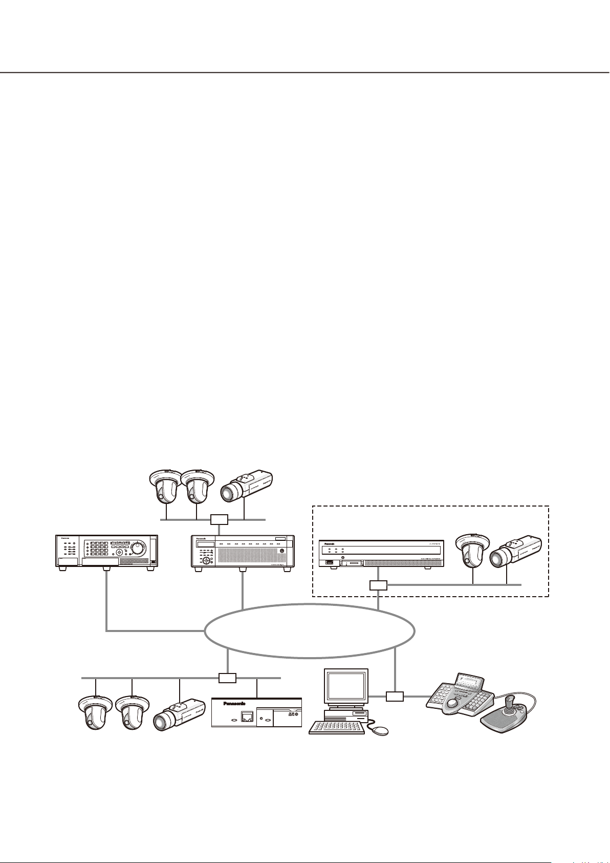
The PC Software Package WV-ASM200 (hereinafter this software) is designed for integrated management of
multiple Panasonic network disk recorders and digital disk recorders (hereinafter recorders), network interface
unit (hereinafter encoders) and network cameras (hereinafter cameras) connected to a network such as a LAN
or the Internet, and runs on the Microsoft® Windows® operating system.
Refer to the "Compatible devices" section (+ page 5) for the devices compatible with this software.
By using this software on a personal computer (hereinafter PC) via a network, it is possible to display live
images of the cameras, to play images stored on the recorder, and to download image files to the hard disk
drive of the PC.
Software configuration
This software consists of the following 3 applications:
Setup software: The settings required to run the operation software can be configured
and managed with this software.
Operation software: Displaying live images, playback, downloading, searching for images
stored on the recorder, and controlling of the camera is available using
this software.
Service software: Reception of Panasonic alarm protocol and auto deletion of the operation
log will be carried out by this software.
This is the resident application (in the system tray). Once the PC is turned
on, the service software runs in the background of the PC.
System configuration

4
5
†1: When the system is configured as "System A" in the illustration above, live images from the cameras con-
nected to the recorder can directly be monitored with this software, not through the recorder.
To monitor live images directly from the cameras with this software, the following are necessary.
Register cameras in the recorder. •
The recorder should be used with a single port.•
†2: The system controller is optional.
Important:
Do not use cross cables to connect the PC and each device.•
When connecting multiple system controllers, operation of this software is not guaranteed.•
System specifications
•Recorderregistration: Upto100recorders
•Encoderregistration: Upto64encoders
•Cameraregistration: Upto256cameras
•Decoderregistration: Upto10decoders(ThelicensefortheWV-ASE204isrequired.)
•Userregistration: Upto32users
•Userlevels: 5levels
•Groupregistration: Upto400groups
•Sequenceregistration: Upto10sequences(Upto64stepscanberegisteredforasequence)
•Mapregistration: Upto100maps(Upto64camerascanbeassignedonamap,upto20
registered maps can be used.) (The file size shall be less than 10 MB.
Available file type is JPEG and BMP.)
•Numberofthealarmlogsthatcanbestored: Upto30000logs(Upto1000logscanbedisplayed)
•Numberofthedeviceerrorlogsthatcanbestored: Upto1000logs(Upto1000logscanbedisplayed)
•Numberofthenetworkerrorlogsthatcanbestored: Upto1000logs(Upto1000logscanbedisplayed)
•Numberofthesystemlogsthatcanbestored: Upto1000logs(Upto1000logscanbedisplayed)
•Numberoftheoperationlogsthatcanbestored: Upto100000logs(Upto1000logscanbedisplayed)
•Numberofsearchresultsthatcanbedisplayed: Upto1000logs search results (Up to 200 results for
VMD search)
Note:
Number of PCs that can concurrently access a single recorder differs depending on choosing whether or •
not to use "Live window" and the model of the recorder in use.
Recorder Use of "Live window"
Yes No
ND300 4 6
ND200 2 4
HD300
ND400 8 16
HD600 4 8
NV200 1 1
ASR500
†3
When exceeding the maximum number of concurrent access due to an increase in the number of accesses •
using web browsers or FTP accesses, connection to the recorder may be interrupted and a black screen
may be displayed.
By adding the license for the Extension Software WV-ASE203 (option), it will become possible to expand the •
maximum numbers of registered recorders, encoders and cameras to 100, 64 and 256 respectively. Up to 4
licenses for the WV-ASE203 can be added.
†1
2
†4 †4
3
†2
†1: When displaying images on a 16-screen or
9-screen, only a single PC can access.
†2: When displaying images on a 16-screen, 2 PCs
can access.
†3: Under the following conditions, connection to the
recorder may be interrupted and a black screen
may be displayed.
Event recording and sequence are being oper-•
ated.
The total live rate for each HD300 is 15 ips or •
more
Refer to "WV-ASM200 Setup Instructions" for
how to configure the settings for the live rate
for HD300.
†4: Note that it varies depending on the system con-
figuration in use.

5
Compatible devices
The following devices are compatible with this software.
Important:
Some functions may not work depending on the firmware version of the compatible device. •
Refer to the Panasonic support website (http://security.panasonic.com/pss/security/support/index.html) for
further information.
Note:
Refer to the operating instructions of the recorder in use for the cameras that can be connected to the re-•
corder in use.
Compatible recorders
Model Appears in this document as Version Compression
ND300 series
ND200 series
HD300 series
ND400 series
HD600 series
NV200 series
ASR500 series
ND300 5.20 or later MPEG-4
M-JPEG
H.264
ND200 3.30 or later MPEG-4
M-JPEG
H.264
HD300 3.44 or later Model-specific
ND400 2.20 or later MPEG-4
M-JPEG
H.264
HD600 2.06 or later H.264
NV200 1.04 or later MPEG-4
M-JPEG
H.264
ASR500 5.9.1901.48362
or later
MPEG-4
M-JPEG
H.264
Compatible encoder
Model Appears in this document as Version Compression
WJ-NT304 NT304 1.32 or later MPEG-4
M-JPEG
WJ-NT314 NT314 1.32 or later MPEG-4
M-JPEG
WJ-GXE500 GXE500 1.30 or later H.264
MPEG-4
M-JPEG
WJ-GXE100 GXE100 1.72 or later H.264
M-JPEG
Compatible cameras
Refer to the Readme.txt on the provided CD-ROM.
Compatible decoder (The license for the WV-ASE204 is required.)
Model Appears in this document as Version Compression
WJ-GXD400 GXD400 2.20 or later H.264
MPEG-4
M-JPEG

6
7
Features
Important:
To use the following functions, it is necessary to add the license for the Extension Software WV-ASE201 •
(option).
Live window•
Map window•
Control using the System Controller WV-CU950•
Refer to the WV-ASM200 Setup Instructions (PDF) for further information about how to add the license for
the Extension Software.
To control the GXD400, it is necessary to register the license for the Extension Software WV-ASE204 (op-•
tion) additionally.
To use the following functions, it is necessary to add the license for the Extension Software WV-ASE• 231
(option).
Face search monitor•
Remote operation of devices
It is possible to operate the recorder, encoder and cameras via a network using this software. When operating
the recorder via a network, displaying live images, playback of recorded images, camera operation, status indication, searching, etc. are available.
Refer to the following chapters for further information.
"Status bar" (+ page 23)
"Monitor live images" (+ page 45)
"Operate the cameras" (+ page 63)
"Playback" (+ page 67)
"Search" (+ page 72)
Multi-monitor function
The multi-monitor function using up to four PC monitors is available, and it makes possible to display the operation window, the live window and the map window simultaneously.
Refer to the "Operate using the multi-monitor function" (+ page 59) for further information.
To use the multi-monitor function, it is necessary to add the license for the Extension Software WV-ASE201.
Image download
It is possible to download recorded images by designating the time range and the target recorders or cameras.
Refer to the "Download recorded images" section (+ page 64) for further information.
Alarm/event notification and management of logs
Alarm notification:• The alarm description will be displayed in a pop-up window (alarm notification window)
on the operation window when an alarm occurrence is notified from the recorder. The alarm description will
also be displayed as a log in the alarm log panel.
Event notification:• The error description will be displayed in a pop-up window (error notification window)
on the operation window upon a recorder error occurrence or upon a network error occurrence. The error
description will also be displayed as a log in the device error log panel or in the network error log panel.
Management of logs:• Each time an alarm or an error occurred, a log will be filed automatically. Logs can
be checked in the log panels (alarm log panel, device error log panel and network error log panel) by log
type (alarm log, device error log and network error log) respectively.
When a log displayed in the log panel is clicked, playback of the respective recorded images will start.
Refer to the "Alarm/event notification and management of logs" section (+ page 112) for further information
about the management of logs.

7
Security
It is possible to enhance security by using the user authentication function (requires entering a user name and
password). This software manages the administrator (who can administrate this software) and the registered
users (who can operate this software except configurations).
It is also possible to restrict operable functions by applying the user level to each registered user.
Refer to the "User management" section (+ page 18) for further information about the user management.
Important:
Check if the model in use is compatible with each function. •
Refer to the Panasonic support website (http://security.panasonic.com/pss/security/support/index.html) for
further information.
Standard accessories
CD-ROM .......................................................... 1 pc.
Installation guide ............................................. 1 pc.
Activation Key Card ......................................... 1 pc.
Important:
The provided CD-ROM contains the installer of this software, the operating instructions (PDF), the setup in-•
structions (PDF) and the Readme.txt.
Prior to installation, read the Readme.txt.
This software will not work if the license is not registered. After installing the software on the PC in use, reg-•
ister the license.
About the user manuals
There are two PDF manuals (the operating instructions and the setup instructions) and the installation guide
(leaflet).
This PDF manual contains descriptions for the registered users such as descriptions about the functions of the
operation software and of how to operate the operation window.
Refer to the WV-ASM200 Setup Instructions (PDF) for descriptions of how to install this software and about the
required preliminary settings before starting running this software.
"WV-ASE201" shown in the instructions and illustrations used in this manual indicates the WV-ASE201,
WV-ASE201W.
"WV-ASE202" shown in the instructions and illustrations used in this manual indicates the WV-ASE202,
WV-ASE202W.
"WV-ASE203" shown in the instructions and illustrations used in this manual indicates the WV-ASE203,
WV-ASE203W.
"WV-ASE204" shown in the instructions and illustrations used in this manual indicates the WV-ASE204,
WV-ASE204W.
The descriptions in the following pages are based on the assumption that Microsoft® Windows® 7 Professional
runs on a PC.
Operation windows may not be the same as those appearing on the pages when a different OS is used or different settings are applied.
When using other OS, refer to the operating instructions of the respective OS.

8
9
Trademarks and registered trademarks
Adobe, Acrobat Reader and Reader are either registered trademarks or trademarks of Adobe Systems •
Incorporated in the United States and/or other countries.
Microsoft, Windows, Windows Vista, Internet Explorer, Active X and DirectX are either registered trademarks •
or trademarks of Microsoft Corporation in the United States and/or other countries.
Microsoft product screen shot(s) reprinted with permission from Microsoft Corporation.•
Intel and Intel Core are trademarks or registered trademarks of Intel Corporation in the United States and •
other countries.
All other trademarks identified herein are the property of their respective owners.•
About use of open source software
This product uses open source software.
Software name Copyright License name
OpenCV Intel Corporation
Willow Garage Inc
Dynamic Json neuecc <ils@neue.cc> Ms-PL
Extended WPF Toolkit Xceed Software Inc. Ms-PL
The following are the entire text of the license agreements to be applied.
License Agreement For Open Source
Computer Vision Library (BSD License)
License Agreement For Open Source Computer Vision Library (BSD License)
IMPORTANT: READ BEFORE DOWNLOADING, COPYING, INSTALLING OR USING.
By downloading, copying, installing or using the software you agree to this license.
If you do not agree to this license, do not download, install, copy or use the software.
License Agreement
For Open Source Computer Vision Library
Copyright© 2000-2008, Intel Corporation, all rights reserved.
Copyright© 2008-2010, Willow Garage Inc., all rights reserved.
Third party copyrights are property of their respective owners.
Redistribution and use in source and binary forms, with or without modification, are permitted provided that the
following conditions are met:
* Redistribution's of source code must retain the above copyright notice, this list of conditions and the following
disclaimer.
* Redistribution's in binary form must reproduce the above copyright notice, this list of conditions and the fol-
lowing disclaimer in the documentation and/or other materials provided with the distribution.
* The name of the copyright holders may not be used to endorse or promote products derived from this soft-
ware without specific prior written permission.
This software is provided by the copyright holders and contributors "as is" and any express or implied warranties, including, but not limited to, the implied warranties of merchantability and fitness for a particular purpose
are disclaimed.

9
In no event shall the Intel Corporation or contributors be liable for any direct, indirect, incidental, special, exemplary, or consequential damages (including, but not limited to, procurement of substitute goods or services;
loss of use, data, or profits; or business interruption) however caused and on any theory of liability, whether in
contract, strict liability, or tort (including negligence or otherwise) arising in any way out of the use of this software, even if advised of the possibility of such damage.
Microsoft Public License (Ms-PL)
This license governs use of the accompanying software. If you use the software, you accept this license. If you
do not accept the license, do not use the software.
1. Definitions
The terms "reproduce," "reproduction," "derivative works," and "distribution" have the same meaning here as
under U.S. copyright law.
A "contribution" is the original software, or any additions or changes to the software.
A "contributor" is any person that distributes its contribution under this license.
"Licensed patents" are a contributor's patent claims that read directly on its contribution.
2. Grant of Rights
Copyright Grant- Subject to the terms of this license, including the license conditions and limitations in section
3, each contributor grants you a non-exclusive, worldwide, royalty-free copyright license to reproduce its contribution, prepare derivative works of its contribution, and distribute its contribution or any derivative works that
you create.
Patent Grant- Subject to the terms of this license, including the license conditions and limitations in section 3,
each contributor grants you a non-exclusive, worldwide, royalty-free license under its licensed patents to make,
have made, use, sell, offer for sale, import, and/or otherwise dispose of its contribution in the software or derivative works of the contribution in the software.
3. Conditions and Limitations
(A) No Trademark License- This license does not grant you rights to use any contributors' name, logo, or trade-
marks.
(B) If you bring a patent claim against any contributor over patents that you claim are infringed by the software,
your patent license from such contributor to the software ends automatically.
(C) If you distribute any portion of the software, you must retain all copyright, patent, trademark, and attribution
notices that are present in the software.
(D) If you distribute any portion of the software in source code form, you may do so only under this license by
including a complete copy of this license with your distribution. If you distribute any portion of the software
in compiled or object code form, you may only do so under a license that complies with this license.
(E) The software is licensed "as-is." You bear the risk of using it. The contributors give no express warranties,
guarantees or conditions. You may have additional consumer rights under your local laws which this license
cannot change. To the extent permitted under your local laws, the contributors exclude the implied warranties of merchantability, fitness for a particular purpose and non-infringement.
Abbreviations
These are descriptions of the basic terms used in these operating instructions.
Microsoft•
described as Windows Vista.
Microsoft•
described as Windows 7.
Microsoft® Windows•
®
Windows Vista® Business SP2 (32-bit) and Microsoft® Windows Vista® Business SP2 (64-bit) are
®
Windows® 7 Professional SP1 (32-bit) and Microsoft® Windows® 7 Professional SP1 (64-bit) are
®
8 Pro (32-bit) and Microsoft® Windows® 8 Pro (64-bit) are described as Windows 8.

10
11
Document convention
These are descriptions of the basic terms used in these operating instructions.
Administrator
Indicates a person responsible for management and
operation of this software.
User
Indicates a person who operates this software. Each
user should be defined as an administrator or a registered user in this software. Only a user who is registered as an administrator can configure and maintain
this software.
Recorder
Indicates Panasonic network disk recorders or digital
disk recorders.
Refer to the "Compatible devices" section (+ page 5)
for the devices compatible with this software.
Encoder
Indicates Panasonic network interface unit.
Refer to the "Compatible devices" section (+ page 5)
for the devices compatible with this software.
Fixed camera
Indicates cameras without the panning and tilting
functions.
PTZ camera
Indicates cameras featuring the panning, tilting and
zooming functions.
Fisheye camera
Indicates Panasonic Fisheye network cameras.
Sequence
Images of each registered group can be displayed
sequentially in the order determined in advance.
The sequence function of this software is available
only for live image display.
EL-zoom
Indicates the zoom function available when displaying
live or recorded images.
While the zoom function of the camera enlarges
images using the zoom lens of the camera, the
EL-zoom function enlarges images by processing
images on this software.
Clicking a point in the EL-zoomed image moves the
displayed EL-zoomed image by positioning the
clicked point as the center point.
Camera operation
Indicates the operations of the camera connected,
such as panning/tilting, zooming, focusing, starting
the preset function (move to the preset position),
starting the selected auto mode function, brightness
adjustment, preset registration and AUX control.
Network playback
Recorded images on the recorder can be played via a
network.
Manual recording
Indicates recording that is performed by clicking the
[REC START] button and the [REC STOP] button.
Live image
Indicates live images from the camera.
Decoder
Indicates Panasonic network video decoders. Refer
to the "Compatible devices" section (☞ page 5) for
the devices compatible with this software.
Direct image reception
Indicates that image reception directly from a camera
registered in the network disk recorder, not through
the recorder.
Group display
Images from cameras can be registered as a group
and displayed by groups.
Download
Indicates file (recorded image on the recorder) transfer from the recorder to a PC using the FTP function.
Image file
Indicates downloaded recorded image from the
recorder.
File playback
Indicates playback of image files using the viewer
software.
Notification function using the Panasonic
alarm protocol
Indicates the function that uses alarm/event notification transmitted from the device using Panasonic
alarm protocol.

11
Application log
Indicates logs filed each time when this software
obtains information about an alarm or a device error
occurrence from the recorder, or when an operation
of this software is made, etc.
The application logs are filed as distinct logs; alarm
log, device error log, network error log, system log
and operation log.
Recorder log
Indicates logs filed each time when a recorder error
or a network error occurred in the recorder.
The recorder logs are generated in the recorder.
The recorder logs are filed as distinct logs; error log,
access log, event log and network log.
M-JPEG
Indicates a video codec that compresses video fields
from the camera into independent JPEG images
sequentially.
Network load will be reduced comparing with the
method that obtains JPEG images independently
from the camera. However, the transmission rate will
fluctuate depending on the state of the camera.
Some cameras phrase this video codec as just
"JPEG".
Operation software
Indicates the application used for displaying live
images of the recorders, encoders and cameras,
playback, downloading, searching for images stored
on the recorder, and controlling the camera.
Operation window
Indicates the window used to operate all functions
except for configurations of this software.
Live window
Indicates the window used only for the group or
sequence display of live images.
Map window
Indicates the window that displays a map with the
registered camera icons.
It is possible to display live images from the desired
camera by clicking the respective camera icon on the
map.
SD memory download
Indicates the function featured in some Panasonic’s
cameras that transfers H.264 video files (mp4 files)
saved on the SD memory card equipped with the
camera to a PC using the FTP function.
REC event
Indicates the reason (an event or an operation) why
the recording started.
The recording event will be described as follows.
Manual, schedule, emergency, site alarm, terminal
alarm, command alarm, VMD, video loss, SD memory
backup
SD memory recording (SD memory data)
Indicates the function featured in some Panasonic’s
cameras that transfers images saved on the SD memory card on the camera to the recorder.
Recorded images transferred to the recorder are
described as "SD memory data" in these operating
instructions.
The recording time of SD memory data will be displayed based on the clock of the camera.
Setup software
Indicates the application used to configure the settings required to run the operation software.
Smooth & fast playback mode
Indicates the mode that can play back all the frames
without skipping when playing back Step 2 and
Step 3.
License
Registration is surely required before using this software. Refer to the provided "Activation Key Card" to
obtain and register the "Registration Key". The
obtained "Registration Key" can be used only on the
PC in which the software is installed.
Demo edition
It is possible to use all the functions of the designated
software for 90 days by registering the license for the
demo edition.
Face search monitor
This window is used to perform operation relating to
the face search. The real time alarm display, face/
alarm search and age/gender report will be executed
on this window.

12
13
Restrictions when operating MPEG-4 or H.264 images
There are following restrictions for each function when MPEG-4 or H.264 images are used with this software.
Read the following before operating this software.
1. When displaying live images
Black screen may be displayed for the first few seconds (*) when the following operations are performed •
while displaying live images in MPEG-4 or H. 264 format.
When trying to display live images in MPEG-4 or H. 264 format. (By switching camera channel, etc.)•
When MPEG-4 or H.264 image is enlarged•
Example: When "3 seconds" is selected for the refresh interval on the camera, MPEG-4 or H.264 images will
be refreshed in 3 seconds intervals.
When displaying SXVGA images• , live images will be displayed with the following interval.
When images are obtained from a recorder, encoder or camera • other than ASR500, images on 16-/25-/
36-/49-/64-screen will be displayed with the refresh interval (*). (All images will be kept displayed for several seconds from the moment when the images are displayed.)
When images are obtained from ASR500• , images on 1-screen will be refreshed with the live rate speci-
fied on the recorder. Images being displayed on 4-/9-/16-/25-/36-/49-/64-screen will be refreshed at 1
second interval. When displaying images on a multi-screen, image refresh delay of 5 seconds or less
may sometimes occur.
When displaying FULL HD images, live images will be displayed with the following interval.•
When images are obtained from a recorder, encoder or camera other than ASR500, images on •
4-/9-/16-/25-/36-/49-/64-screen will be displayed with the refresh interval (*). (All images will be kept dis-
played for several seconds from the moment when the images are displayed.)
When images are obtained from ASR500, images on • 1-screen will be refreshed with the live rate specified
on the recorder.
Images on 4-/9-/16-/25-/36-/49-/64-screen will be refreshed at 1 second interval. When displaying images
on a multi-screen, image refresh delay of 5 seconds or less may sometimes occur.
2. When playing recorded images
Displayed playback time may be fast for several seconds (*) when the following operations are performed •
while playing recorded MPEG-4 or H. 264 images.
When trying to display playback images in MPEG-4 or H. 264 format. (By switching camera channel, •
etc.)
When MPEG-4 or H.264 image is enlarged •
(When operating to enlarge a paused recorded MPEG-4 image, image of several seconds later than the
paused image may be enlarged.)
When the [PLAY] button is clicked again while playing MPEG-4 or H.264 images•
Playback may be performed in several seconds intervals (*) when the following operations are performed •
while playing MPEG-4 or H.264 images.
•Reverseplayback
•Fastplayback/Fastreverseplayback
•Reverseframeplayback
Example: When "3 seconds" is selected for the refresh interval on the camera, MPEG-4 or H.264 images will
be played in 3 seconds intervals.
When two records are played sequentially, the last few frames of the former record and the first few frames •
of the next record may be displayed overlapped.
When the [SKIP] button or the [REV SKIP] button is clicked, a skipped point may be a few seconds later (†) •
from a point to be skipped with the selected amount of time or from the first frame of the next record.
Sometimes, playback may start from the beginning of the next record.
When a black screen is being displayed, the following operations are inoperable.•
•Playback/Reverseplayback

13
•Fastplayback/Fastreverseplayback
•Frameplayback/Reverseframeplayback
•Skippingtothenext/previousrecordedimage
•Skippingtothepointofthesetamountoftimeforward/backward
•Pause
When playing images by designating time & date, playback may start from a point several seconds (†) after •
the designated time & date. Sometimes, playback may start from the beginning of the next record.
When displaying SXVGA images• , recorded images will be displayed with the following interval.
When images are obtained from a recorder, encoder or camera • other than ASR500, images on
16-/25-/36-/49-/64-screen will be displayed with the refresh interval (*). (All images will be kept displayed
for several seconds from the moment when the images are displayed.)
When images are obtained from ASR500• , images on 1-screen will be refreshed with the live rate speci-
fied on the recorder. Images being displayed on 4-/9-/16-/25-/36-/49-/64-screen will be refreshed at 1
second interval. When displaying images on a multi-screen, image refresh delay of 5 seconds or less
may sometimes occur.
When displaying FULL HD images, recorded images will be displayed with the following interval.•
When images are obtained from a recorder, encoder or camera other than ASR500, images on •
4-/9-/16-/25-/36-/49-/64-screen will be displayed with the refresh interval (*). (All images will be kept dis-
played for several seconds from the moment when the images are displayed.)
When images are obtained from ASR500, images on • 1-screen will be refreshed with the recording rate
specified on the recorder.
Images on 4-/9-/16-/25-/36-/49-/64-screen will be refreshed at 1 second interval. When displaying
images on a multi-screen, image refresh delay of 5 seconds or less may sometimes occur.
3. When downloading recorded images
Download of recorded images may start from a point several seconds (†) after the designated start time.
Set the time range for download longer than the refresh interval set on the camera.
Important:
Time (seconds) and intervals with an asterisk (†) differ depending on the refresh interval set on the camera. •
(Valid entry range: Differs depending on the model number of the camera.)
To shorten time lag, set the refresh interval on the camera shorter. •
Refer to the operating instructions of the camera for how to configure the refresh interval.
14
15
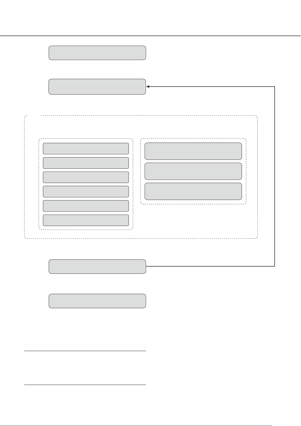
Operation flow
z
x
c
Startup of the operation software
➜ ➜
Login
Operation window
Monitoring of live images
Searching for recorded images
Playback of recorded images
Saving of recorded images
z Refer to the "Start/exit the operation software"
section (☞ page 15) for how to start the operation
software.
x Log in to the software.
When using the multi-monitor function
Live window
Map window
Face search monitor
Printing of images
Alarm/error notification
➜ ➜
v
b
† For frequent users, it is unnecessary to log in at
startup of the software when using the auto login
function.
Only an administrator can configure the settings
for the auto login function.
Note:
When a message window is displayed by clicking •
the button on the window, refer to the "Displayed
messages and solutions" section (☞ page 130)
and follow the instructions.
Exit the operation software
Logout
v
User switch
c The operation window will be displayed.
Searching, playback and saving of the displayed
image are available using the menu panel and the
tool bar.
Refer to the "Operation window" section (☞ page
21) for further information.
v Log out of the software when finishing operation.
It is possible to log in to the software again using
another user name (user switch).
Refer to the "User switch" section (☞ page 20) for
further information.
b Exit from the operation software.
15
Start/exit the operation software
Start the operation software
Important:
Registration of the license is required before using •
this software. This software will not work if the license is not registered.
Register the license for the software after confirm-•
ing that the network adapter of the PC is enabled.
If the license has not been registered using the •
setup software, register it by following from step 2
to 5.
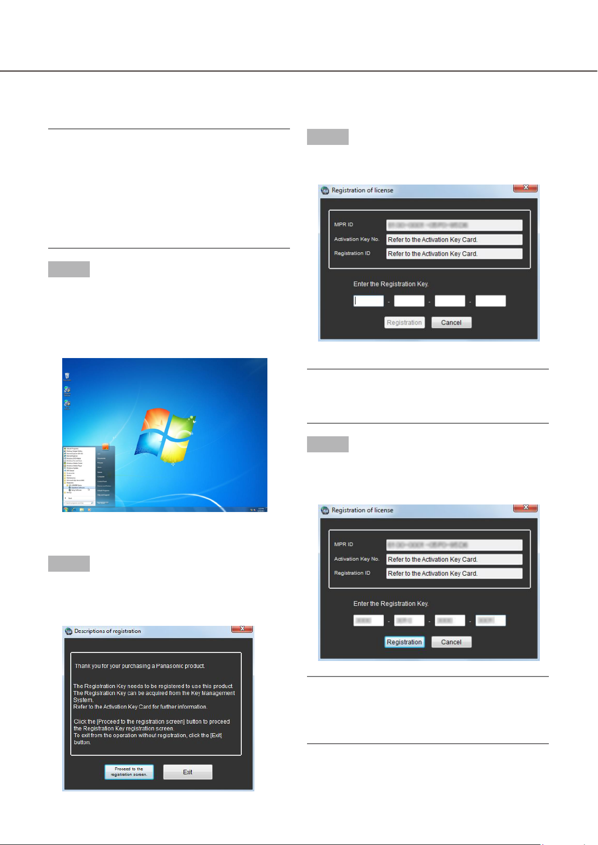
Step 1
Select "Operation Software" from "start" menu
("Start" - "All Programs" - "Panasonic" "WV-ASM200 Series" - "Operation Software") or double-click the "Operation Software" icon on the desktop to launch the operation software.
Step 3
Enter the "Registration Key" obtained from the Key
Management System.
Important:
The "Registration Key" can be used only on a PC •
that displays "MPR ID" (used to obtain the key) on
its screen. It cannot be used on other PCs.
The explanation window for registration will be
displayed.
Step 2
After reading the message on the explanation window, click the [Proceed to the registration screen.]
button.
Step 4
Click the [Registration] button.
The confirmation window for registration will be
displayed.
Important:
It is impossible to register the "Registration Key" •
of the extension software (option).
Be sure to perform the registration procedure on •
the PC in use.
16
17
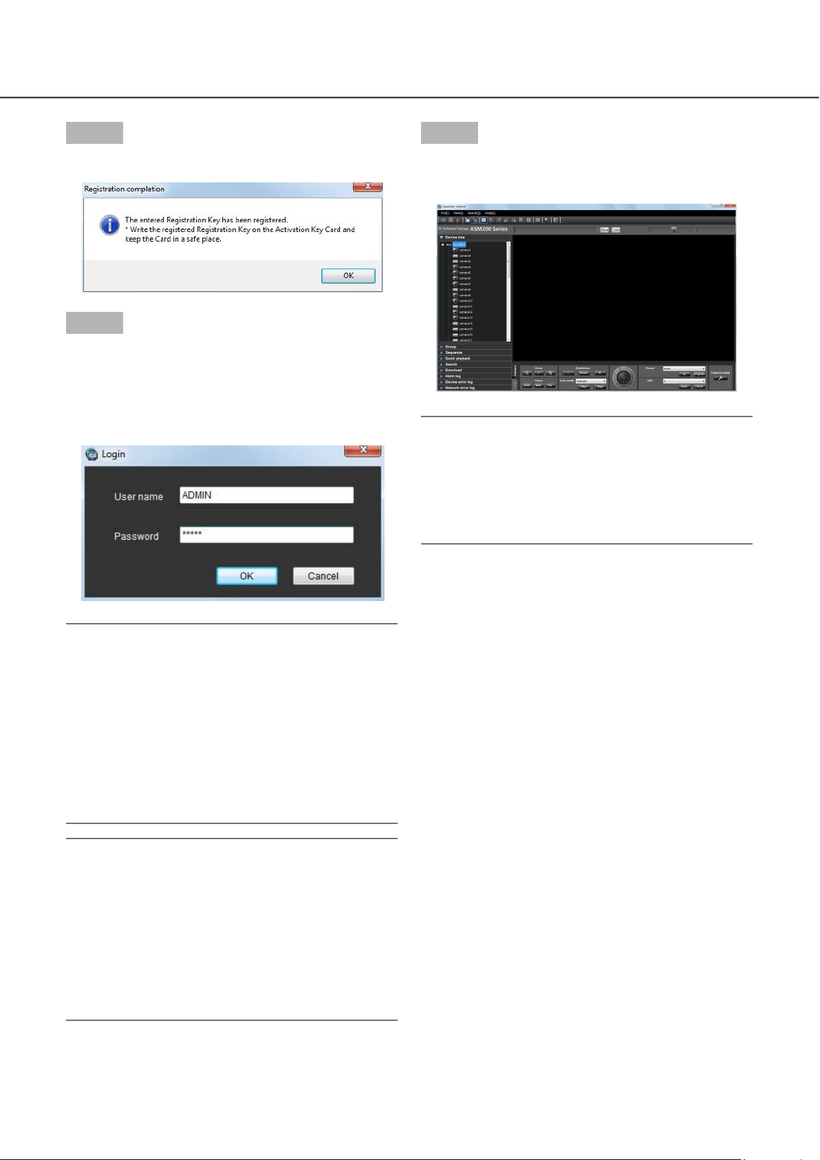
Step 5
Step 7
Click the [OK] button.
Step 6
Enter the registered user name and password.
Only an administrator is registered when operating
the software just after the installation.
Enter "ADMIN" for "User name" and "12345" for
"Password" respectively.
Click the [OK] button.
The operation window will be displayed.
Note:
Unless otherwise mentioned, the screenshots of •
the operation window is in the status before the license for the Extension Software WV-ASE202 is
added. After the license is added, the icon display
on the tool bar will be changed as shown in
page 22.
Important:
It is necessary to close the setup software to start •
the operation software.
The operation software will not start unless the
setup software is closed.
To enhance the security, change the password for •
an administrator before running the software.
It is recommended to change the password for •
the administrator periodically. Refer to the descriptions for how to change the password
(+ page 19).
Note:
It is possible to register a user as the auto login •
user when the same user name is used each time
to log in to the software. The default setting of
"User authentication" for each registered user is
"ON" (required the user name and password entries). Only an administrator can configure the setting of "User authentication" on the setup software. Refer to the WV-ASM200 Setup Instructions
(PDF) for further information.
17
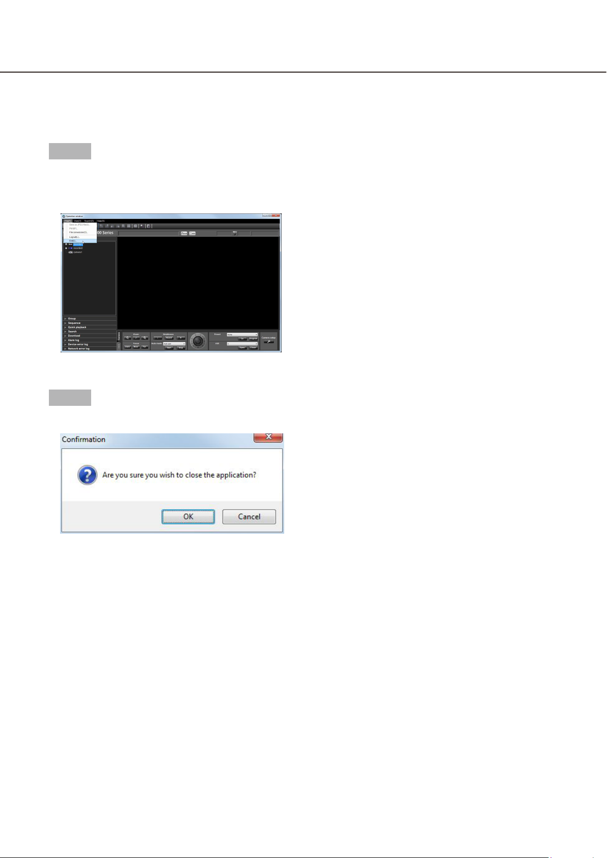
Exit the operation software
Step 1
Select "Exit(X)..." from "File(F)" on the menu bar or
click the [×] button at the top right of the operation
window.
The confirmation window will be displayed.
Step 2
Click the [OK] button.
The operation software will be closed.

18
19
User management
Two types of users, the administrator and the registered users, can be managed with this software.
Only an administrator can configure the settings of this software. When a registered user logged in to the software, only the available menus will be displayed according to the user level setting of this registered user. Only
an administrator can configure the user level setting of the registered users. Refer to the WV-ASM200 Setup
Instructions (PDF) for how to configure the user level setting.
Important:
When using this software, apply the user authentication function of this software to manage users even •
though the recorders also have the function.
About the user level setting
It is possible to assign the user level to each user to restrict their operable functions. This software can assign
one of five user levels (LV1 – LV5) to every user. When "LV1" is assigned to a user, this user can operate all
functions of the software except configurations. An administrator can determine the operable functions for each
user by assigning the user level "LV2" – "LV5".
The following functions can be restricted according to the user levels.
Default:
Function LV1 LV2 LV3 LV4 LV5
Display the current settings
Alarm reset/error reset
Print/Save as JPEG file
File conversion
Download
Manual recording
Recorder control
Preset position registration
Operation of SD memory card
Camera control
Audio (Transmission)
Display the alarm log
Display the device error log
Display the network error log
Face registration
Display alarm/Display face search result
b
b
b b
b b
b b
b
b b b
b b b b
b b
b b b b
b b b b
b b b b
b b b b
b b b b
b
b b b
19
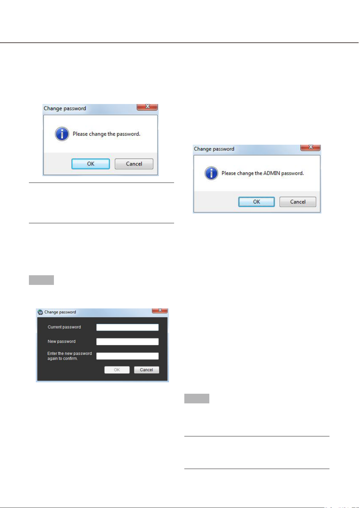
Password’s validation period
The password’s validation period can be determined (31 days/92 days/184 days) by an administrator.
When trying to log in after the set period passed, the message window saying "Please change the password."
will be displayed.
When this software is being operated without changing the password, the following message window saying "Please change the ADMIN password." will be displayed.
Note:
Even when the validation period has passed, the •
password will be authorized. However, this message window will be displayed each time the user
tries to log in.
Change the password
To enhance the security, change the password when this message window is displayed.
Step 1
Click the [OK] button on the message window.
The "Change password" window will be displayed.
n Current password
Enter the current password.
The entered password will be displayed as "*".
n New password
Enter the new password. The entered password will
be displayed as "*".
Enter up to 4 - 8 alphanumeric characters.
n Enter the new password again to confirm.
Enter the new password again. Enter the same password.
The entered password will be displayed as "*".
n [OK] button
Click this button to apply and save the new password. (The window will close.) The [OK] button cannot
be clicked unless all entries are completed.
n [Cancel] button
Click this button to cancel the entries. (The window
will close.)
Step 2
Complete all of the entry fields on the "Change password" window, and then click the [OK] button.
The new password will be applied and saved.
Important:
Refer to the WV-ASM200 Setup Instructions (PDF) •
for how to change the password of the administrator.
20
21
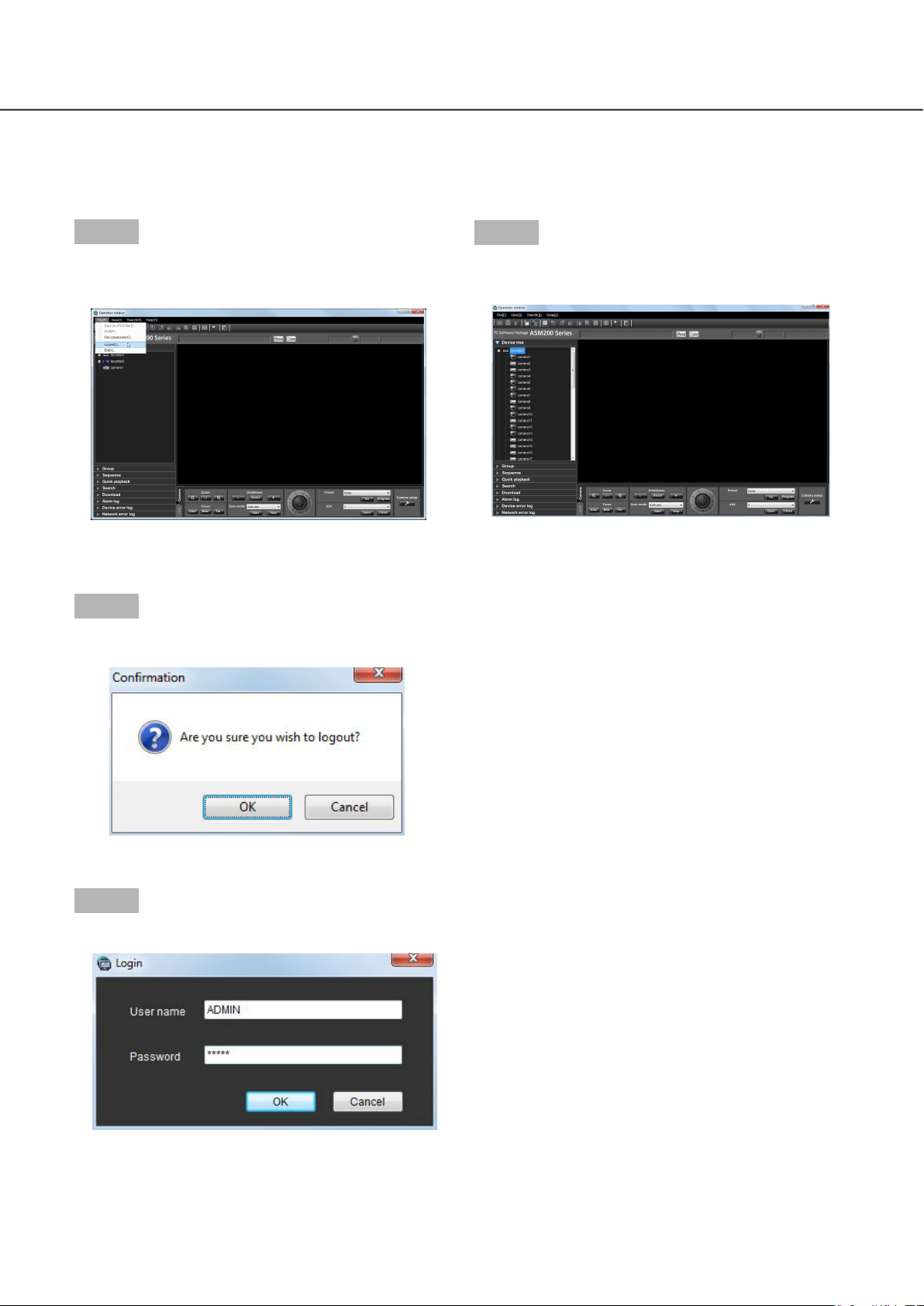
User switch
It is possible to switch users.
Step 1
Select "Logout(L)..." under "File(F)" on the menu bar
or double-click the [Logout] icon on the tool bar.
The confirmation window will be displayed.
Step 2
Click the [OK] button.
Step 4
Click the [OK] button.
The operation window will be displayed.
The "Login" window will be displayed.
Step 3
Enter the registered user name and password.

21
Operation window
The operation window will be displayed when logged in to the operation software. The following are descriptions about each item displayed on the operation window.
Menu bar
Tool bar
Status bar
Information display area
Function panel
Operation panel
n Menu bar
The menu items are located on the menu bar. Refer
to the descriptions about the "Menu bar" (+ page 22)
for further information.
n Tool bar
The shortcut icons of the menu items are located on
the tool bar. Refer to the descriptions about the "Tool
bar" (+ page 22) for further information.
n Status bar
The following statuses will be displayed on the status
bar.
Display status (live/playback/SD memory data) of •
the images currently being displayed
Playback speed of the images currently being •
played
Recorder (encoder) title/camera title•
Recorder status (recording/copying/deleting of •
data)
Alarm occurrence/error occurrence•
Presence or absence of SD memory data in the •
SD memory card of the camera
Time & date•
Refer to the descriptions about the "Status bar" (+
page 23) for further information.
n Function panel
The function panel is provided on the left of the operation window. When the desired function bar on the
function panel is clicked, the respective function
panel will be displayed. Refer to the "Function panel"
section (+ page 26) for further information.
n Image display area
Images will be displayed on the selected screen type
(1/4/9/16-screen). The screen type can be changed
simply by clicking the shortcut icons on the tool bar.
When right-clicking on this area, the pop-up menu
will be displayed. (Selection from the displayed popup menu is available only when right-clicking on a
1-screen.) Refer to the descriptions about the pop-up
menu (+ page 28) for further information.
The descriptions of the alarm/error will be displayed
in a pop-up window (notification window) on the
operation window upon an alarm/error occurrence.
Refer to the descriptions about the alarm/event notification window (+ page 113) for further information.
n Information display area
Information of the images currently displayed, such
as time & date, camera title and the recording status,
will be displayed in this area.
Refer to the "Information display area" section (+
page 29) for further information.
22
23
n Operation panel
The cameras and recorders are operable with this
panel. Refer to the description about the "Camera
operation panel" (+ page 29) and about the
"Playback operation panel" (+ page 32) for further
information.
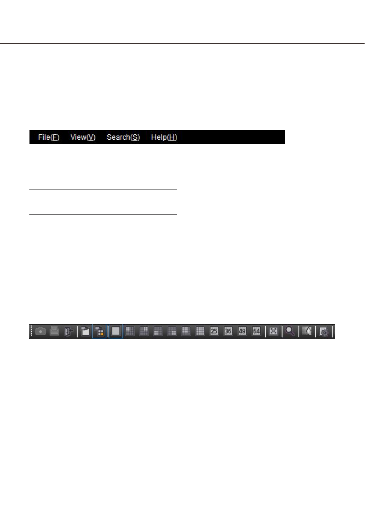
Menu bar
n File(F)
Contains the following menus; "Save as JPEG file",
"Print", "File conversion", "Logout" and "Exit".
Note:
"Save as JPEG file" and "Print" are also available •
from the pop-up menu displayed by right-clicking.
n Search(S)
Contains the shortcut menu to open the "Search"
window.
n Help(H)
It is possible to indicate the version information and
license registration information.
n View(V)
Contains the following menus; "Function panel",
"Operation panel", "Camera/time & date", "Camera
selection", "Number of area", "Full screen", "Live window", "Map window" and "Decoder control" (after the
license for the WV-ASE204 is added).
Tool bar
The following are the descriptions of icons located from the left to the right.
n [Save as JPEG file] icon
Click this icon to save the image currently being displayed as a JPEG file.
n [Print] icon
Click this icon to print the image currently being displayed.
n [Logout] icon
Click this icon to log out of the software. The login
window will be displayed when this icon is clicked.
n [Display images on 1-screen] icon
When the device tree or the camera icon on the map
is clicked, a live image on a 1-screen will be displayed.
n [Display images on the selected area] icon
When the device tree or the camera icon on the map
is clicked, live images will be displayed in the
selected frame.
n [1] icon
Click this icon to display images on a 1-screen.
n [4A] icon
Click this icon to display images using 4 areas at the
upper left of a 16-screen.
n [4B] icon
Click this icon to display images using 4 areas at the
upper right of a 16-screen.

23
n [4C] icon
Click this icon to display images using 4 areas at the
lower left of a 16-screen.
n [4D] icon
Click this icon to display images using 4 areas at the
lower right of a 16-screen.
n [9] icon
Click this icon to display images using 9 areas at the
upper left of a 16-screen.
n [16] icon
Click this icon to make the image display area into a
16-screen.
n [25] icon (Available after the license for the
WV-ASE202 is added)
Click this icon to make the image display area into a
25-screen.
n [36] icon (Available after the license for the
WV-ASE202 is added)
Click this icon to make the image display area into a
36-screen.
n [49] icon (Available after the license for the
WV-ASE202 is added)
Click this icon to make the image display area into a
49-screen.
n [64] icon (Available after the license for the
WV-ASE202 is added)
Click this icon to make the image display area into a
64-screen.
n [Full screen] icon
Click this icon to display the image currently being
displayed on a full screen.
n [Search] icon
Click this icon to display the "Search" window.
Refer to the descriptions about the "Search window"
(+ page 35) for further information.
n [Face search] icon (Available after the
license for the WV-ASE231 is added)
Click this icon to launch the face search monitor.
n [File conversion] icon
Click this icon to display the window to convert an
n3r file into an mp4 file. Refer to the "Convert a file to
the standard format" section (+ page 102) for further
information.
n [Decoder control] icon
Click this icon to display the "Decoder control" window. Refer to the descriptions about the "Control a
decoder" (+ page 104) for further information.
Status bar
Important:
Check if the model in use is compatible with each function. •
n Recorder title/camera title
Source (recorder (encoder) title and the camera title)
of the image currently being displayed will be displayed in this area.
n [ALM] button
The button will be used when the emergency recording is being performed or when an event occurred.
When the button is clicked, the alarm action will be
canceled.
Note:
When the recorder in use is the ND300 (Version •
4.69 or earlier) or the HD300, the error action also
will be canceled.
When the recorder in use is the ND300 or the •
HD300, the button will not be used even when the
emergency recording is being performed.
This button will not be displayed when using •
ASR500.

24
25
n [ERR] button
The button will be used when an error occurred.
When the button is clicked, the error action will be
canceled.
When the [SD] button is clicked while the letters •
"SD" are displayed in red, recorded images on the
SD memory card will be transferred to the recorder (SD memory data).
Note:
When the recorder in use is the ND300 (Version •
4.69 or earlier) or the HD300, the alarm action also
will be canceled.
When the recorder in use is the WJ-HD300, the •
error action will not be canceled even when the
button is clicked.
In this case, refer to the operating instructions of
the recorder in use for how to cancel an error action.
This button will not be displayed when using •
ASR500.
n [SD] button (Button to obtain the SD
memory data)
When the SD memory card in the camera connected
to the recorder contains recorded images, the letters
"SD" on the [SD] button will be displayed in red.
When the button is clicked, the recorded images on
the SD memory card will be transferred to the
recorder.
Important:
When the recording rate for the SD memory re-•
cording is not set, the SD memory data obtain
button will not be displayed. Refer to the operating instructions of the recorder in use for how to
set the recording rate for the SD memory recording.
The SD memory data cannot be obtained during •
the emergency recording. Refer to the operating
instructions of the recorder in use for further information about the emergency recording.
Depending on the recorder in use, all login users •
will be forcibly logged out and recording of images from all cameras currently being performed
will stop when obtainment of the SD memory data
starts.
Note:
The letters "SD" on the [SD] button will be dis-•
played in blue when there is no recorded image in
the SD memory card.
When the [SD] button is clicked while the letters •
"SD" are displayed in blue, this software will
check the presence of recorded image on the SD
memory card. Images saved on the SD memory
card will be transmitted to the recorder depending
on the model of the recorder in use.
n [Mic input] button
Click this button to turn on/off the audio reception
(from camera to PC). When is displayed, audio
will not be heard.
Note:
When right-clicking on this button, the pop-up •
menu will be displayed. It is possible to change
the volume level of audio reception by selecting
"High", "Middle" or "Low" from the displayed
pop-up menu.
When displaying images on a multi-screen, audio •
will be transmitted to the camera which is the
source of images displayed in the upper-left area
of the multi-screen. When another area is selected, audio associated with images displayed in
the upper-left area of the multi-screen will still be
heard, though this button will disappear.
When audio is being transmitted to the same •
camera by another user, this button will turn to .
In addition, audio from the camera will not be
heard. (Audio will be heard even when audio is
being transmitted depending on the model in use.)
This button will not be displayed when using •
ASR500.
n [Audio output] button
Click this button to turn on/off the audio transmission
(from PC to camera). When is displayed, audio will
not be heard.
Note:
Volume level of audio transmission cannot be •
changed. (Depending on the camera in use, volume level of audio transmission can be adjusted
by configuring the settings of the camera.)
When displaying images on a multi-screen, audio •
will be transmitted to the camera which is the
source of images displayed in the upper-left area
of the multi-screen. When another area is selected, audio will still be transmitted to the camera
which is the source of images displayed in the upper-left area, though this button will disappear.
When audio is being transmitted to the same •
camera by another user, this button will turn to
In addition, audio from the camera will not be
heard.
.

25
It is possible to transmit audio up to 5 minutes per •
transmission. When 5 minutes elapsed, the audio
reception will be turned on automatically.
To transmit audio again, click the [Audio transmission] button.
This button will not be displayed when using •
ASR500.
n [LIVE]/[PLAY]/[SD PLAY]
Indicates the type (live/playback/SD memory data
playback) of the images currently being displayed.
n [Step 1] - [Step 7]
Indicates the playback speed. ( ): Smooth & fast playback mode
[Step 1]: Normal playback speed
[Step 2]: Approx.4x playback speed (Approx.2x
playback speed)
[Step 3]: Approx.8x playback speed (Approx.4x
playback speed)
[Step 4]: Approx.16x playback speed (Approx.8x
playback speed)
[Step 5]: Approx.32x playback speed (Approx.16x
playback speed)
[Step 6]: Approx.48x playback speed (Approx.32x
playback speed)
[Step 7]: Approx.96x playback speed (Approx.64x
playback speed)
n Time & date
When displaying live images, the time & date of the
selected device will be displayed. Time & date will not
be displayed except for some devices when images
directly from the camera are being displayed or when
images from a camera that is not registered in the
recorder are being displayed.
When displaying recorded images, the recording time
& date will be displayed.
When "24h" is selected for "Time format" (+ Setup
Instructions (PDF)), the indications will not be displayed.
The time & date will be followed by an asterisk "*"
when the daylight saving time is applied.
n Buffering
Indicates that the images are being buffered during
playback. When images are being buffered, playback
will be paused. The playback will start when the buffering of images are completed.
Note:
This indicator will work only when the recorder in •
use is ASR500.
Note:
ASR500 plays recorded images in the high-speed •
playback smooth mode. The maximum playback
speed using ASR500 is [Step 5].
n REC indicator
This indicator will light red when the recording of the
images currently selected is being performed.
Note:
This indicator will not be displayed when using •
ASR500.
n [COPY]/[DELETE]
[COPY]: Indicates that copying of image data is being
performed.
[DELETE]: Indicates that deletion of image data is
being performed.
26
27
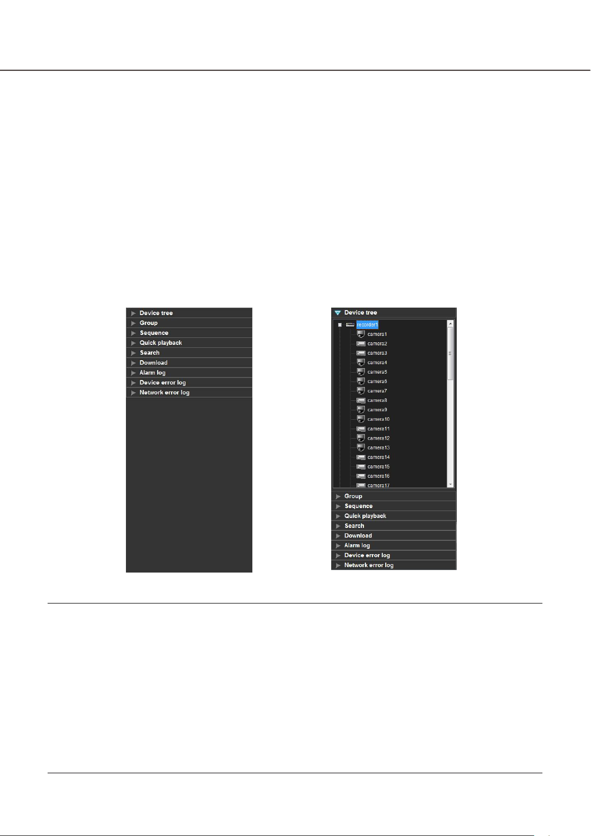
Function panel
The following are available using the function panel located at the left side of the operation window.
Display the device tree (the icons of the connected devices in the tree view), and display images by clicking •
the desired camera icon
Group display•
Sequence display•
Quick playback•
Search•
Download•
Display the alarm log•
Display the device error log•
Display the network error log•
When one of the function bars is clicked, the respective function panel will open. (It is impossible to open two
or more panels at the same time.)
B
Note:
Refer to the following about the descriptions of how to operate each function panel.•
"Device tree" panel Confirm the registered devices (+ page 45)
"Group" panel Display images from the cameras registered as a group (group display)
(+ page 52)
"Sequence" panel Display images from the cameras registered as a group sequentially
(sequence display) (+ page 53)
"Quick playback" panel Play images using the "Quick playback" panel (+ page 69)
"Search" panel Play recorded images using the "Search" panel (+ page 77)
"Download" panel Download recorded images (+ page 95)
"Alarm log" panel "Alarm log" panel (+ page 120)
"Device error log" panel "Device error log" panel (+ page 121)
"Device error log" panel "Network error log" panel (+ page 122)
27
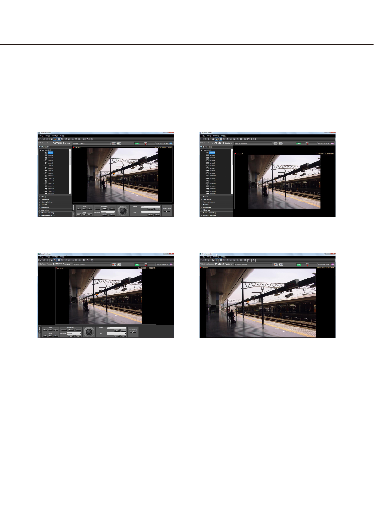
Layout of the operation window
It is possible to hide the operational panel and the function panel of the operation window as follows.
Refer to the "Menu bar" section (+ page 22) for further information.
n With the operation panel and the function
panel
n Without the function panel n Without the operation panel and the
n Without the operation panel
function panel
28
29
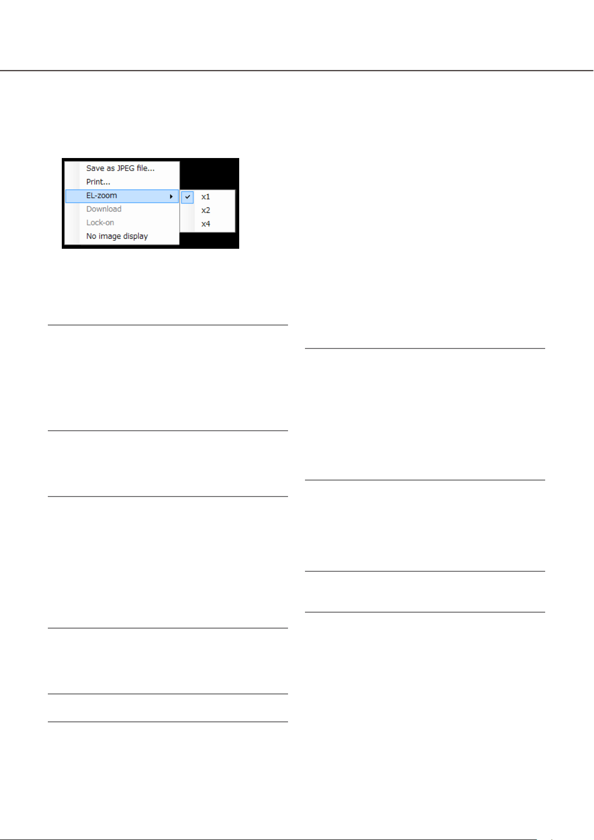
Pop-up menu
When right-clicking on the image display area, the pop-up menu will be displayed. (Selection from the displayed pop-up menu is available only when right-clicking on a 1-screen.)
n Save as JPEG file...
Select this to save the image currently being displayed as a JPEG file.
Note:
"Save as JPEG file..." on the pop-up menu will not •
be displayed when the user is restricted by the
user level determined by the administrator to save
an image as a JPEG file.
Refer to the "About the user level setting" section
(+ page 18) for further information about the user
level.
n Print...
Select this to print the image currently being displayed.
Note:
n EL-zoom
Select this to enlarge the image currently being displayed. "x1", "x2" and "x4" are available.
†
Select this to print the image currently being dis-•
played.
"Print..." on the pop-up menu will not be dis-•
played when the user is restricted by the user
level determined by the administrator to print images.
Refer to the "About the user level setting" section
(+ page 18) for further information about the user
level.
†
†
n Download...
Select this to open the "Download" panel. Information
(recorder title/camera title/time & date) of the
recorded image currently being played will be displayed in the opened "Download" panel.
Note:
"Download" on the pop-up menu will not be dis-•
played when the user is restricted by the user
level determined by the administrator to download
recorded images.
Refer to the "About the user level setting" section
(+ page 18) for further information about the user
level.
When displaying live images, it is impossible to •
select "Download" on the pop-up menu.
n Lock-on
Select this to start auto track for the object on the
clicked point. Depending on the target object or surrounding environment, this function may not work
correctly.
Note:
This function is available only when the camera in •
use is WV-SC386 or WV-SW396.
†
†
n No image display
Clear the currently displayed image.
Note:
This button will not be used when using ASR500.•
29
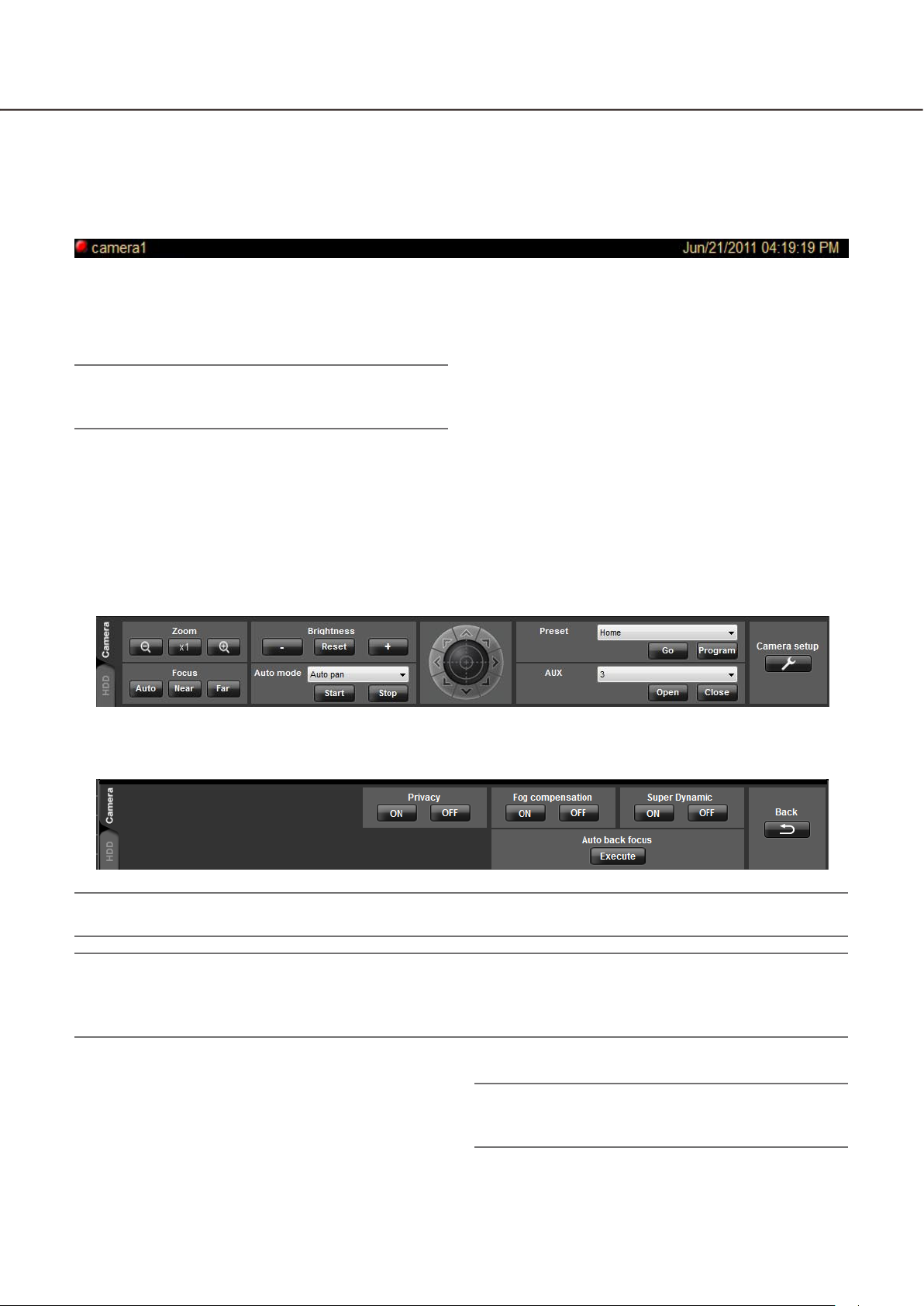
Information display area
Information of the images currently displayed, such as time & date, camera title and the recording status, will be
displayed in this area.
n REC indicator
This indicator will light when the recording of the
images currently selected are being performed.
Note:
This indicator will not be displayed when using •
ASR500.
n Camera name
The camera title as the source of the image currently
being displayed will be displayed.
Camera operation panel
n Time & date
Time & date will be displayed. Time & date will not be
displayed except for some devices when images
directly from the camera are being displayed or when
images from a camera that is not registered in the
recorder are being displayed. The time & date will be
followed by an asterisk "*" when the daylight saving
time is applied.
Display when the [Camera setup] button is clicked
Important:
Check if the model in use is compatible with each function. •
Note:
Operation of the camera operation panel works only for the camera respective the selected image.•
The camera operation panel will not be displayed when the user is restricted by the user level determined by •
the administrator to operate the cameras.
n Zoom
Zooming can be adjusted by clicking the [-] (wide)
button or the [+] (tele) button.
When clicking the [x1] button, the zoom ratio will be
reset.
Note:
Zooming is available using the wheel on the wheel •
mouse.

30
31
n Focus
The auto focus function can be performed by clicking
the [Auto] button.
Focusing can be manually adjusted by clicking the
[Near] button or the [Far] button.
n Brightness
Brightness can be adjusted by clicking the [–] (darker)
button or the [+] (brighter) button.
It is possible to reset the set brightness by clicking
the [Reset] button.
n Auto mode
Select the auto function from the following.
Auto track: The camera automatically tracks motion
of the subject displayed in the image display area.
Auto pan: The camera automatically moves from the
start point to the end point set in advance.
Preset sequence: The camera automatically moves to
the preset positions in numerical order of the preset position numbers.
Sort: The camera automatically moves to the closest
preset position from the current position.
Patrol1 - Patrol4: The camera automatically traces the
route set in advance.
When the [Start] button is clicked, the selected auto
function will start.
When the [Stop] button is clicked, the selected auto
function will stop.
Note:
The auto functions are available only when the •
camera in use has these functions. Refer to the
operating instructions of the camera in use for further information about the auto function of the
camera.
While "Quad PTZ" is selected for the image cap-•
ture mode of Fisheye cameras, the auto functions
will be performed for the image displayed at the
upper left area of the 4-screen.
n Control pad
Clicking the buttons around the control pad can move
(pan/tilt) a camera in the clicked direction. Clicking
inside the control pad also can adjust the vertical/horizontal position (pan/tilt) of the displayed live images.
Panning/tilting speed will be faster if a clicked point
gets farther from the center point of the control pad.
Note:
Panning and tilting are available only when the •
camera in use is a PTZ camera.
Clicking a point on the image display area can •
move (pan/tilt) a camera in the clicked direction.
n Preset
Select a preset number from the following.
Home/1 - 256
Click the [Go] button after selecting a preset number.
The camera will move to the selected preset position.
When the [Program] button is clicked after selecting a
preset number, the current position will be registered
as the preset position of the selected preset position
number.
Note:
Preset position function is available only when the •
camera in use is a PTZ camera.
It is impossible to register a position when •
"Home" is selected for the preset position
number.
It is possible to register the preset position only •
when the user is not restricted by the user level
determined by the administrator to operate the
cameras.
Refer to the "About the user level setting" section
(+ page 18) for further information about the user
level.
Refer to the operating instructions of the recorder •
and the camera in use for further information
about the available preset position numbers.
While "Quad PTZ" is selected for the image cap-•
ture mode of Fisheye cameras, the preset position
currently displayed at the upper left area of the
4-screen will be registered.
n AUX
Select an AUX OUT connector from the following.
1/2/3
When the [Open] button is clicked, the selected AUX
OUT connector will be opened.
When the [Close] button is clicked, the selected AUX
OUT connector will be closed.
n Camera setup
Click this button to move to the panel to configure the
settings for the camera.
 Loading...