

Page 1

PC Software Package
Operating Instructions
Model No. WV-AS710A
Before attempting to connect or operate this product,
please read these instructions carefully and save this manual for future use.
Page 2

CONTENTS
Features .................................................................................................................................. 4
■ Introduction ....................................................................................................................... 4
■ Function ............................................................................................................................ 5
■ System Requirements ....................................................................................................... 6
■ Standard Accessories ....................................................................................................... 8
■ Trademarks and Registered Trademarks ......................................................................... 8
■ Structure of These Operating Instructions ........................................................................ 9
Operation .............................................................................................................................. 10
How to Use the "TOP MENU" ................................................................................................ 12
How to Use the Camera Page ............................................................................................... 13
Camera Selection Menu ........................................................................................................ 14
How to display the camera selection menu ........................................................................... 14
Live Picture Display Area ....................................................................................................... 15
Live Single Screen ........................................................................................................... 15
Live Multi Screen Display ................................................................................................ 16
Live Sequence Display .................................................................................................... 17
Live Mode Panel ................................................................................................................. 18
How to display the live mode panel .................................................................................. 18
Playback of Recorded Pictures ........................................................................................... 21
Downloading Recorded Picture ........................................................................................ 22
Play Downloaded Recorded Picture ................................................................................. 22
To play MPEG-4 ............................................................................................................... 23
Searching Menu .................................................................................................................. 24
"Time & Date Search" ....................................................................................................... 24
"Time & Data" Search Results ......................................................................................... 25
"Event Search" .................................................................................................................. 26
"Event Search" Results ..................................................................................................... 27
Play Picture Display Area ................................................................................................... 28
Spot Playback Screen ...................................................................................................... 28
Multiscreen Playback Screen ........................................................................................... 29
Play Mode Panel ................................................................................................................. 30
How to Display the Play Mode Panel ................................................................................ 30
Installation of the MPEG-4 Plug-in Software ...................................................................... 32
How to Install .................................................................................................................... 32
How to Uninstall ................................................................................................................ 32
Installation of the MPEG-4 Player ....................................................................................... 33
How to Install .................................................................................................................... 33
How to Uninstall ................................................................................................................ 33
Installation ............................................................................................................................ 34
Procedures to Establish the Network Camera Server ........................................................ 34
Selection of the System Type ............................................................................................. 35
Confirmation of the Directory Structure .............................................................................. 36
Installation of Red Hat Enterprise Linux ............................................................................. 37
About Disk Space for Recorded Pictures (When "Live View & Recording" is Selected) .. 37
Allocation of Disk Space (When "Live View & Recording" is Selected) .............................. 39
About Disk Space for Recorded Pictures ......................................................................... 39
Cautions When Allocating Disk Space ............................................................................. 39
How to Allocate Disk Space ................................................................................................ 40
Installation of the WV-AS710A ........................................................................................... 41
Mounting the CD-ROM ..................................................................................................... 41
Execution of the Installation Script (Installation by Unpacking the Archive Files) ............. 41
Unmounting the CD-ROM ................................................................................................. 42
Starting up the Network Camera Server ............................................................................. 42
Installation of the Hardware Key ....................................................................................... 42
Start up from the "Administrator's Page" .......................................................................... 42
The Settings of the Network Camera Server Just after Completing the
Installation are as Follows: ............................................................................................... 43
2
Page 3

After the Installation of the WV-AS710A ............................................................................. 44
E-Mail System Establishment ........................................................................................... 44
Environment Settings of the Network Camera Server ...................................................... 44
Stop the WV-AS710A ......................................................................................................... 44
Uninstallation ...................................................................................................................... 45
Administration ..................................................................................................................... 46
How to Display the "Administrator's Page" ......................................................................... 46
List of Settings .................................................................................................................... 48
System Type ....................................................................................................................... 50
Camera Setting ................................................................................................................... 50
Camera List ...................................................................................................................... 50
Camera Properties ............................................................................................................ 52
Preset Title Setting ...........................................................................................................54
Camera Sleep Schedule (8) ............................................................................................. 54
Camera Sleep Schedule (1) ............................................................................................. 55
Camera Sleep Schedule List ............................................................................................ 56
Camera Sleep Schedule Properties ................................................................................. 57
Record Setting .................................................................................................................... 59
Recording Status List ........................................................................................................ 59
Disk Space Allocation for Camera # ................................................................................. 60
Disk Space Setting for Camera # ..................................................................................... 61
Disk Space Addition for Camera # .................................................................................... 62
Delete Disk Space for Camera # ...................................................................................... 63
Clear Protected Disk Space for Camera # ........................................................................ 64
Disk Space Allocation ....................................................................................................... 65
Recording Schedule (8) .................................................................................................... 66
Recording Schedule (1) .................................................................................................... 67
Recording Schedule List ................................................................................................... 68
Recording Schedule Properties ........................................................................................ 69
Alarm Recording ............................................................................................................... 71
Authentication ..................................................................................................................... 73
User List ....................................................................................................................... 74
User Registration ..............................................................................................................75
Change User Profile ......................................................................................................... 76
Level Table Setting ........................................................................................................... 77
System ................................................................................................................................ 78
System Properties ............................................................................................................ 78
Alarm Notification .............................................................................................................. 81
E-Mail Setting ................................................................................................................... 82
Multiscreen Group List ..................................................................................................... 83
Multiscreen Group Properties ........................................................................................... 84
Sequence Group List ....................................................................................................... 85
Sequence Group Properties ............................................................................................. 86
Maintenance ....................................................................................................................... 87
Status ................................................................................................................................ 87
Log .................................................................................................................................... 88
Log Contents .................................................................................................................... 88
User Access Log ............................................................................................................... 91
About Backup and Restoration ......................................................................................... 93
Backup Selection .............................................................................................................. 94
Config Backup ..................................................................................................................94
Recording Data Manual Backup Setting ("Live View & Recording") ................................. 95
Recording Data Schedule Backup Setting ("Live View & Recording") ............................. 96
Recording Data Backup Status (“Live View & Recording”) ............................................... 97
Restore Selection ............................................................................................................. 98
Configuration Restore ....................................................................................................... 99
Recording Data Restore ("Live View & Recording") ....................................................... 100
Restored Recording Data List ("Live View & Recording") .............................................. 101
Stop and Restart ............................................................................................................. 102
Troubleshooting ................................................................................................................. 103
3
Page 4
Features
OS
Hard Disk
Recorded Pictures
Camera Site
Center Site
te
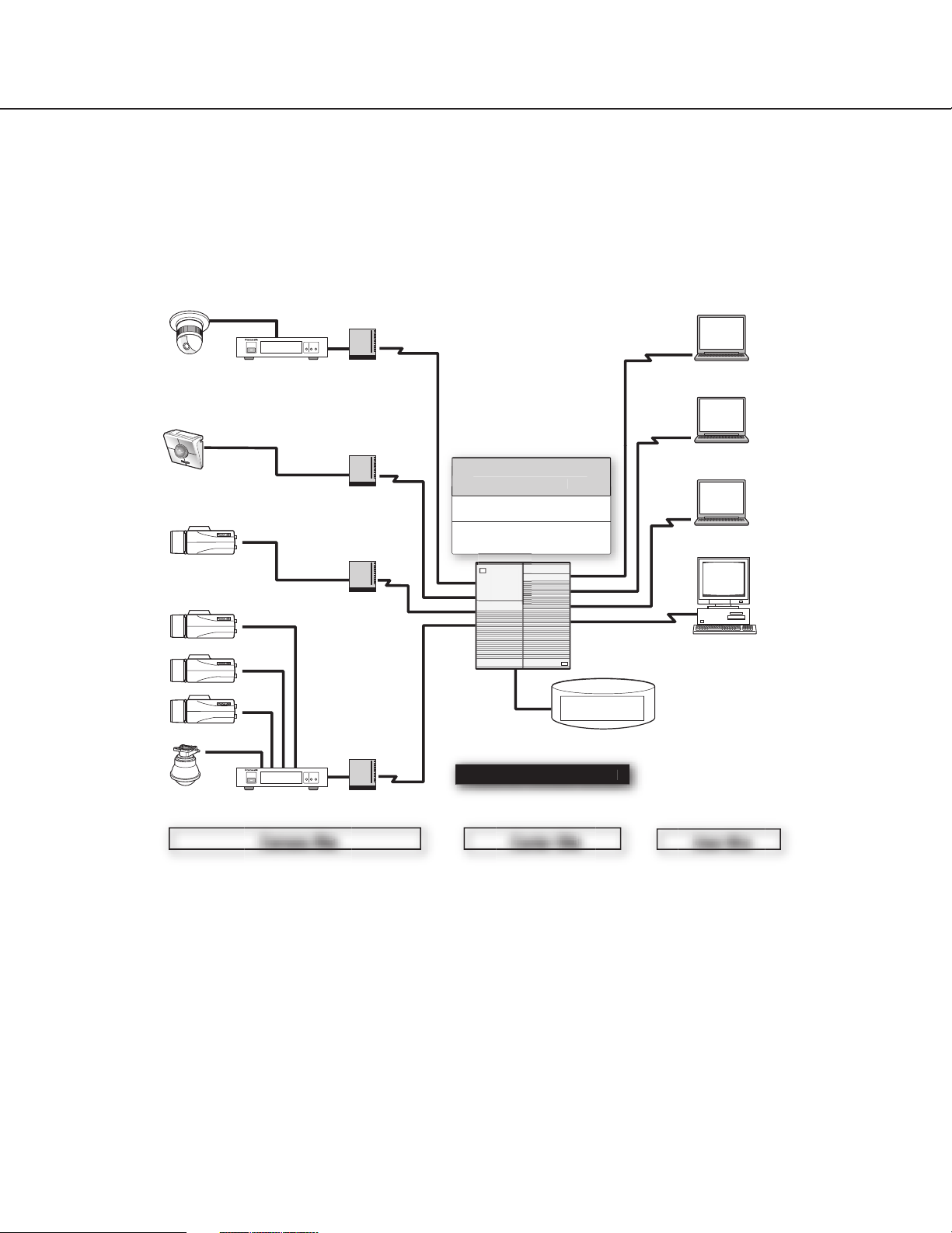
■ Introduction
The PC Software Package WV-AS710A (hereinafter referred to as WV-AS710A) is designed to monitor pictures
from cameras at remote locations on personal computers (PCs) via an IP network such as the Internet/Intranet.
Install the WV-AS710A in a PC server whose OS is Red Hat Enterprise Linux WS 3.0 to run the network camera
server (a PC server in which the WV-AS710A is installed is referred to as a network camera server in this operating
instructions). Users can monitor the pictures using web browsers on PCs.
Coaxial Cable
Camera
Network Camera
Network Camera
Camera
Camera
Camera
Camera
Network Interface Unit WJ-NT104
Network Interface Unit
LAN Cable
LAN Cable
Coaxial Cable
Network Interface Unit WJ-NT104
Network Interface Unit
LAN Cable
Modem/Router
Hub etc.
LAN Cable
PC
PC Software Package
WV-AS710A
Web Server Apache
Red Hat Enterprise Linux WS 3.0
PC Server
Disk Space for
Network Camera Server
4
r Si
Camera Site
When using cameras connected by coaxial cable
Access the network using the network interface unit WJ-NT104. The network camera server identifies the IP address
and the camera channels of the network interface unit, and acquires camera pictures and controls the cameras.
When using network cameras with built-in 10BASE-T/100BASE-TX Ethernet port connected by LAN cable
Access the network assigning unique IP addresses to each camera. The network camera server identifies the IP
addresses assigned to each camera, and acquires camera pictures and controls the cameras.
Page 5

User Site
Users can browse camera pictures by entering the address of the network camera server in the address box of a
web browser in the same way they access web pages using a web browser. Users don’t need to remember the IP
address of each camera thanks to menus displayed in the web browser that allow them to select and operate the
desired camera.
When connected cameras are compatible with MPEG-4, users can browse camera pictures in the MPEG-4 format
by downloading the MPEG-4 Plug-in Software from the network camera server and installing it in the PC. Users also
can download recorded pictures from the network camera server and play them as MPEG-4 motion pictures.
It is required to download the MPEG-4 Player to play downloaded pictures. Download the MPEG-4 Player from the
network camera server and install it in the PC.
■ Function
Network Monitoring
By using the network camera server, users can browse JPEG or MPEG-4 format pictures from cameras at remote
locations in the same way they access web pages using a web browser. Multiple users can browse pictures from the
same camera simultaneously, and also each user can browse pictures from different cameras.
Recordings
Authenticated users can record camera pictures delivered to the network camera server on to hard disks.
Alarm Recordings
When the network camera server receives an alarm signal from a camera, pictures from the camera can be recorded on to a hard disk of the server. In this case, sending e-mail to specified addresses to notify of an alarm occurring
is also possible. The recipients of the alarm mail can browse the recorded camera pictures by following a link contained in the mail.
Note: The network camera server receives alarm signals only when cameras use the Panasonic protocol to transmit
alarm signals.
Administration
Administration of the network camera server (for example, setting of camera numbers) can be performed using a
web browser installed on a PC connected to the network.
It is unnecessary to install special software on a PC since the network camera server is fully operable with a web
browser.
5
Page 6

Features
■ System Requirements
System requirements for using the network camera server differ depending on the sites, as described below.
Center site
Prepare a PC meeting the following requirements to install the WV-AS710A on.
PC CPU: IntelR Xeon™ 2.8 GHz or higher
Memory 512 MB of RAM or more
LAN card 100BASE-TX controller or 1000BASE-T/TX/SX controller (Installing three controllers is
recommended: for camera sites, for user sites, for maintenance)
OS Red Hat Enterprise Linux WS 3.0
CD-ROM drive Required to install the WV-AS710A
USB port Required to install the hardware key (using a USB hub is available)
Hard disk Ultra 160 SCSI or Ultra 320 SCSI, 2 GB or more (except disk space for recorded pictures)
Introducing a RAID is recommended for high tolerance to disk failure.
Core Component As the web server, Apache HTTP Server included in Red Hat
Enterprise Linux WS 3.0 is required.
For the database server, mysgl-server-3.23.58 downloaded from Red Hat Network is
required.
When using the function for alarm notification by e-mail, establishment of a mail system
including a mail server is required.
Camera site
The following cameras can be connected to the network camera server.
Cameras WV-NM100, WV-NS324, WV-NP472 (Ver. 1.08P or later), WV-NW474, or cameras that
can be connected to the network interface unit WJ-NT104 (ver. 3)
Controllable cameras WV-NM100, WV-NS324, WV-NW474, or cameras controllable by WJ-NT104
Maximum camera number "Live View & Recording": 64 cameras
"Live View Only": 128 cameras
User site
Recommended environment to access the network camera server is as below.
For browsing JPEG
PC PC/AT compatible
Recommended CPU Intel®Pentium®lll 700 MHz or higher
Memory 128MB of RAM or more
OS Microsoft®Windows®2000 Professional SP4
Microsoft®Windows®XP Professional SP1a
Web browser Microsoft®Internet Explorer 6.0 SP1
6
Page 7

Note: It is required to configure a web browser to accept cookies from the network camera server. If the web
browser is configured to "Block All Cookies", set it to "Accept All Cookies". If it is configured to prompt
you when a cookie is sent, click the [Allow] button in the displayed dialog window.
For browsing camera pictures with MPEG-4 Plug-in Software
PC PC/AT compatible
Recommended CPU Intel®Pentium®lll700 MHz or higher
Memory 128 MB of RAM or more
Monitor (Resolution) True Color 24 bit or more (XGA or more (1024 x 768 or more))
OS Microsoft®Windows®2000 Professional SP4
Microsoft®Windows®XP Professional SP1a
Web browser Microsoft®Internet Explorer 6.0 SP1
For using MPEG-4 Player
PC PC/AT compatible
Recommended CPU Intel®Pentium®lll700 MHz or higher
Memory 128 MB of RAM or more
Monitor (Resolution) True Color 24 bit or more (XGA or more (1024 x 768 or more))
OS Microsoft®Windows®2000 Professional SP4
Microsoft®Windows®XP Professional SP1a
Hard disk 10 MB or more to install MPEG-4 Player
About Network Environment
Depending on the traffic on the network or the security system of the LAN (e.g. firewall), it may be difficult to display
HTML documents delivered from the network camera server correctly. The HTML documents delivered from the network camera server contain JavaScript and commands to CGIs. When a PC is set to ignore these commands,
HTML documents may not be displayed correctly.
7
Page 8

Features
Notes:
• When the traffic on the network is heavy
When the transmission speed is slow or the traffic on the network is too heavy to receive image data, it may be
difficult to browse camera pictures and a still picture indicating the failure to acquire an image ("Image capture
has failed.") may appear. When this still picture appears frequently, adjust the time interval for acquiring image
data.
• When a firewall (including software) is installed
• Allow HTTP access to a port for Apache (default port number: 80).
• Allow HTTP access to a port for WV-AS710A (default port number: 8080). The port for WV-AS710A can be
changed during installation.
• Allow access to all of the UDP ports. Otherwise, it is impossible to browse motion pictures (MPEG-4).
• Language
Screens can be displayed in American English, British English, or Japanese. Prepare the Windows appropriate
to the language you wish to use.
■ Standard Accessories
CD-ROM* ................................................................................. 1
Installation guide ....................................................................... 1
Hardware key ........................................................................... 1
Software License Agreement .................................................... 1
* CD-ROM includes the install program of the WV-AS710A, the operating instructions (PDF) and the Readme.txt.
Before installation read the Readme.txt.
■ Trademarks and Registered Trademarks
• Linux is a registered trademark of Linus Torvalds.
• RED HAT is a registered trademark of Red Hat, Inc.
• Java is a trademark or registered trademark of Sun Microsystems, Inc. in the United States and other countries.
• Microsoft, and Windows are registered trademarks of Microsoft Corporation in the U.S. and other countries.
• Intel and Pentium are trademarks of Intel Corporation.
• Other names of companies and products contained in these operating instructions may be trademarks or regis-
tered trademarks of their respective owners.
• Distributing, copying, disassembling, reverse compiling, reverse engineering, and also exporting in violation of
export laws of the Software provided with this product, is expressly prohibited.
8
Page 9

■ Structure of These Operating Instructions
These operating instructions consist of an "Operation" section for general users, and "Installation" and
"Administration" sections for administrators of the network camera server. These operating instructions are written
on the assumption that users and administrators use Internet Explorer 6.0 SP1 to operate the network camera server. If other browsers are used, the illustrations in these operating instructions may look differently.
"Operation"
This section describes how to access and operate the network camera server from PCs.
"Installation"
This section describes how to install the WV-AS710A on a PC server on which Red Hat Enterprise Linux WS 3.0 is
installed.
"Administration"
This section describes how to set and administrate the network camera server.
Readers of This Manual
The "Operation" section is written for users who know how to operate a web browser and have general knowledge
about the Internet.
The "Installation" and "Administration" sections are written for users who know how to administrate Red Hat
Enterprise Linux WS 3.0 and the Apache HTTP Server, and who also know how to establish a backbone server.
Terms
Meanings of the terms used in these operating instructions are as follows:
Network camera server: A running PC server on which the WV-AS710A is installed.
Network camera: Cameras that can be directly connected to network such as: WV-NM100, WV-NP472 and WV-
NS324.
Disk space for recorded pictures: Disk space used only for recording which is allocated on a mounted hard disk
on the network camera server. (Partition or directory name is /S3_DATAxx.)
PC: A computer on which a Microsoft®Windows®operating system is installed.
Web browser: Software to browse web sites on the Internet (Internet Explorer).
Administrator: A user registered as level 1.
User: A person who accesses the network camera server using a web browser, and browses camera pictures or
operates cameras.
Alarm picture: A picture captured when an alarm occurs.
Red Hat Enterprise Linux: Red Hat Enterprise Linux WS 3.0.
Windows: Microsoft®Windows®operating system.
Windows 2000: Microsoft®Windows®2000 Professional SP4.
Windows XP: Microsoft®Windows®XP Professional SP1a.
Notes:
• Names of buttons are between square brackets (e.g. the [OK] button).
• Names of menus and items on menus are between double quotation marks (e.g. the "System Properties" menu).
9
Page 10
Operation
This section describes how to access the network
camera server in order to browse camera pictures,
operate cameras, and play recorded pictures.
• Access the network camera server using a web
browser. If you don’t have a recommended web
browser, download it from the distributor. Refer to
the "Help" menu of the web browser or to the web
site of a distributor if you need to learn how to operate the web browser.
• It is required to configure the web browser to
accept cookies from the network camera server. If
the web browser is configured to "Block All
Cookies", set it to "Accept All Cookies". If it is configured to prompt you when a cookie is sent, click
the [Allow] button in the displayed dialog window.
• To browse MPEG-4 pictures, the MPEG-4 Plug-in
Software is required. This Plug-in Software is only
for Internet Explorer 6.0 SP1.
• To browse downloaded MPEG-4 recorded pictures,
the MPEG-4 Player is required.
• To download the MPEG-4 Plug-in Software and the
MPEG-4 Player it is required to agree to the
License Agreement. In the WV-AS710A, 32 licenses are included. Each time the MPEG-4 Plug-in
Software or the MPEG-4 Player is downloaded,
one license is used.
• When accessing the network camera server with
two or more browser windows of a web browser on
a PC, pictures may not be displayed correctly.
• To access cameras with an operating restriction,
the user is required to be registered for authentication. Refer to an administrator for a user name and
a password.
• These operating instructions explain about the
HTML documents installed when the WV-AS710A
is installed. If the HTML documents are edited, layouts and actions may be changed.
Access to the Network camera server
Perform the following to access the network camera
server to browse camera pictures.
1. Start up the web browser and enter one of the following URLs (refer to a system administrator or a
network administrator about the URL):
• Display in English (Date format: Month/Day/Year)
http://(address of server)/s3/American/
• Display in English (Date format: Day/Month/Year)
http://(address of server)/s3/British/
• Display in Japanese
http://(address of server)/s3/Japanese/
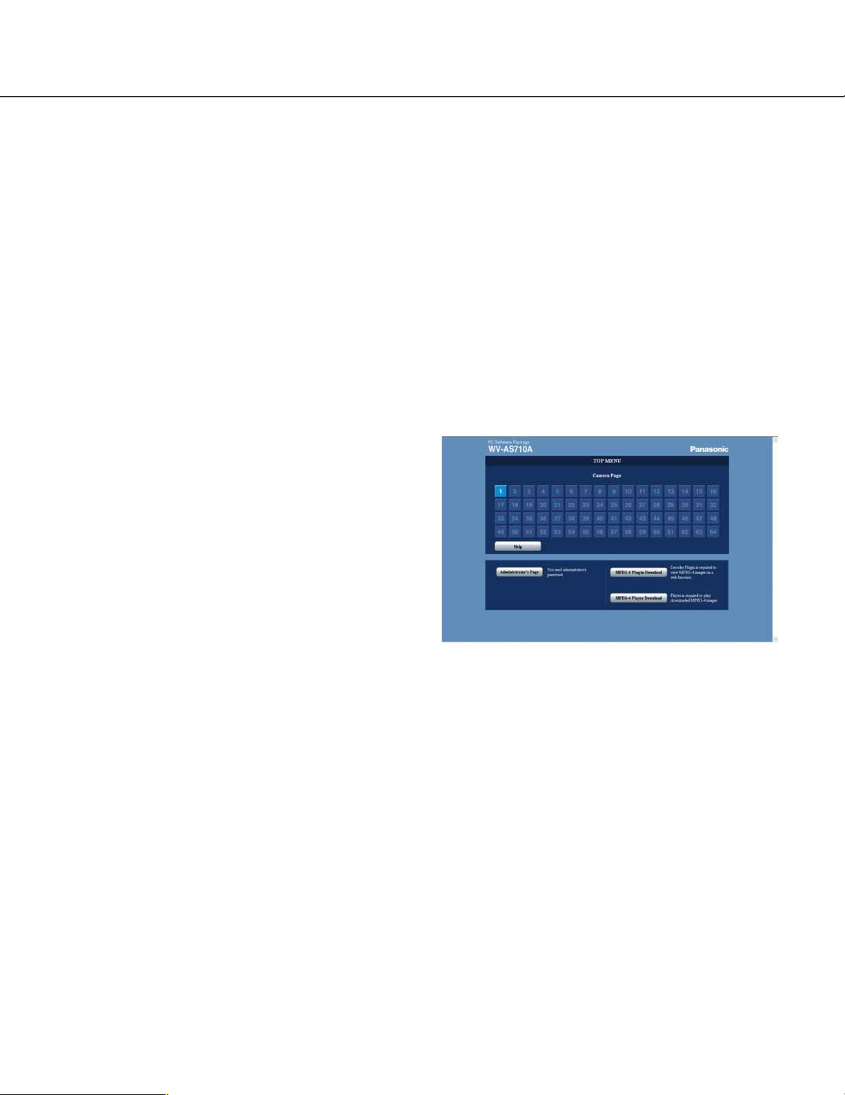
When an address is entered correctly, the "TOP
MENU" will be displayed.
Note: In these operating instructions, procedures are
described on the assumption that the
"http://(address of server)/s3/American/" is entered.
2. To browse camera pictures, click one of the [1] [64] buttons. When "Live View Only" is selected as
the system type of the network camera server, the
[1] - [128] buttons are available.
The buttons for the registered cameras will be
available. Click one of the available buttons to display the "Camera Page".
10
Page 11
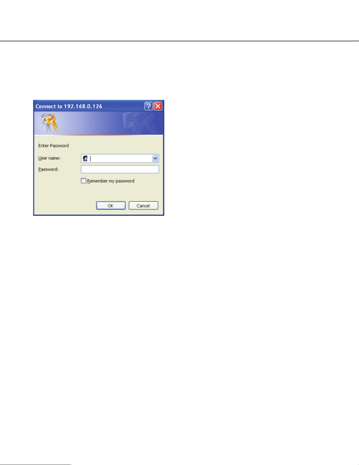
When the authentication dialog window is displayed:
The authentication dialog window will be displayed
when "ON" is selected for "Pre-Authentication Mode"
on the "System Properties" menu.
Enter a user name and a password, and click the [OK]
button.
When authenticated, the "Camera Page" will be displayed.
About "Pre-Authentication Mode"
Users, who have been authenticated when the
"Camera Page" is displayed for the first time, do not
have to be authenticated subsequently. However,
when an authenticated user tries to select or operate a
camera that the user is not allowed to access, the
authentication dialog window will be displayed.
11
Page 12
Operation
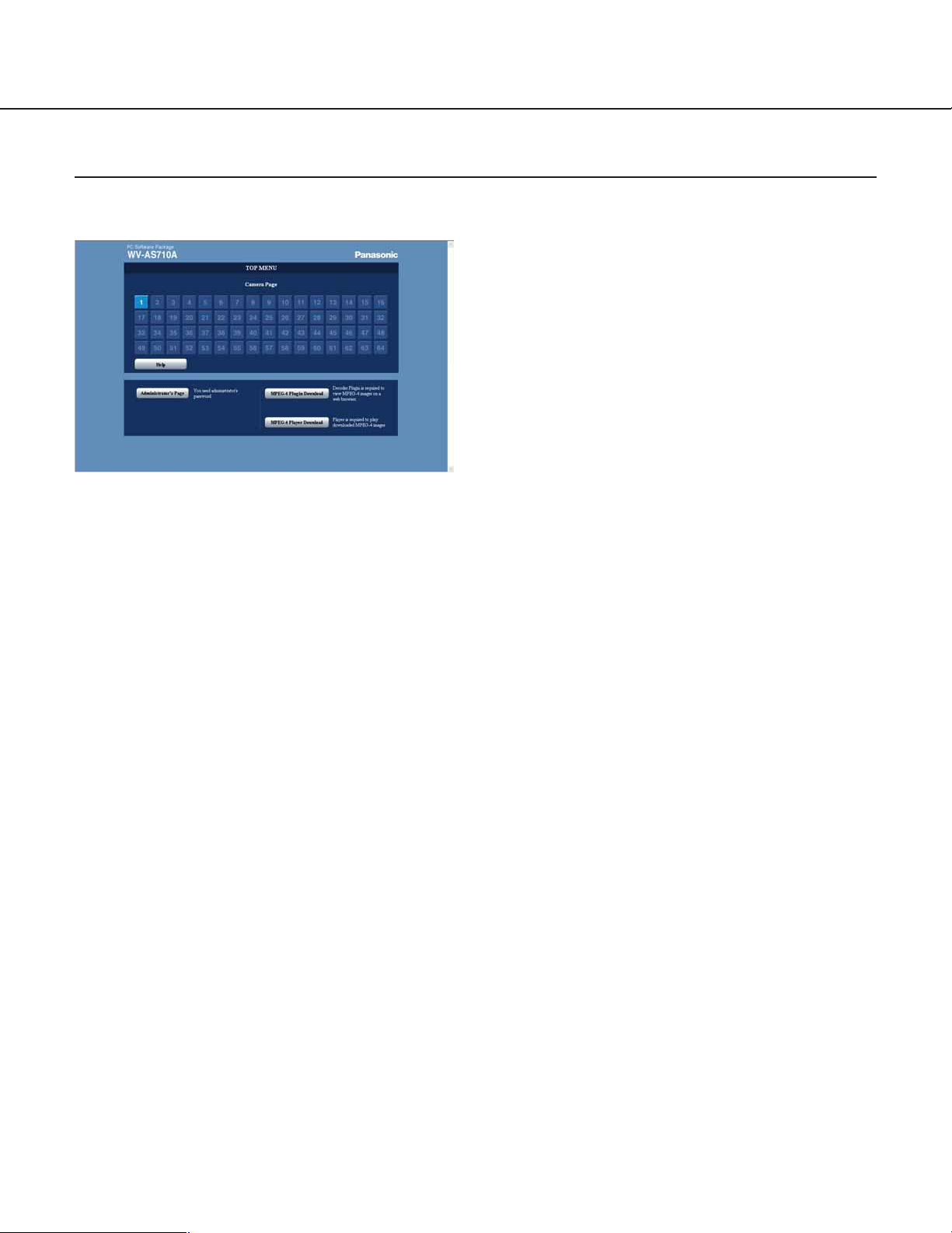
How to Use the "TOP MENU"
To operate the "TOP MENU" page, refer to the following.
"Camera Page" [1] - [64] (when "Live View &
Recording" is selected as the "System Type")/[1] [128] (when "Live View Only" is selected as the
"System Type")
Camera numbers will be displayed. The available
camera numbers are of cameras registered to the
network camera server. When an available button
is clicked, the picture from the selected camera will
be displayed in the selected camera page. The
camera number buttons are different depending on
the selected system type of the network camera
server, as follows:
"Live View & Recording": [1] - [64]
"Live View Only": [1] - [128]
Note: Live camera pictures will not be displayed even
when an available button is clicked, in the following
cases.
• When the network camera server stops delivering camera pictures temporarily. (The network
camera server stops delivering camera pictures
during "Camera Sleep Schedule".)
• When IP addresses of cameras registered to
the network camera server are incorrect.
• When a camera registered to the network camera server is not connected.
• When the network camera server cannot
acquire camera pictures because of connection
trouble, malfunctioning of cameras, etc.
• Even if MPEG-4 Plug-in Software is not
installed on a PC, the network camera server
will deliver MPEG-4 camera pictures. (In this
case, this problem will be solved by downloading MPEG-4 Plug-in Software from the "TOP
MENU" page and installing it.)
[Help] button
Click this button to display the "Help" page.
[Administrator's Page] button
Click this button to display the "Administrator's
Page". Only users registered as a level 1 user can
display the "Administrator's Page". (The user name
and password registered to a level 1 user will be
required.) Refer to the "Administration" section of
these operating instructions.
[MPEG-4 Plug-in Download] button
Click this button to display the MPEG-4 Plug-in
Software download page. The MPEG-4 Plug-in
Software is required to browse MPEG-4 live camera pictures using a web browser.
[MPEG-4 Player Download] button
Click this button to display the MPEG-4 Player
download page. The MPEG-4 Player is required to
play downloaded MPEG-4 pictures stored on the
network camera server.
12
Page 13
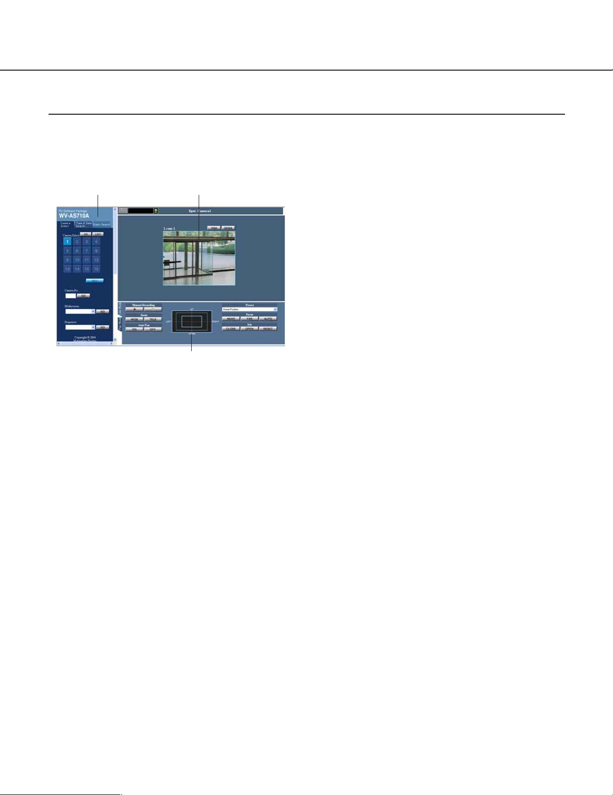
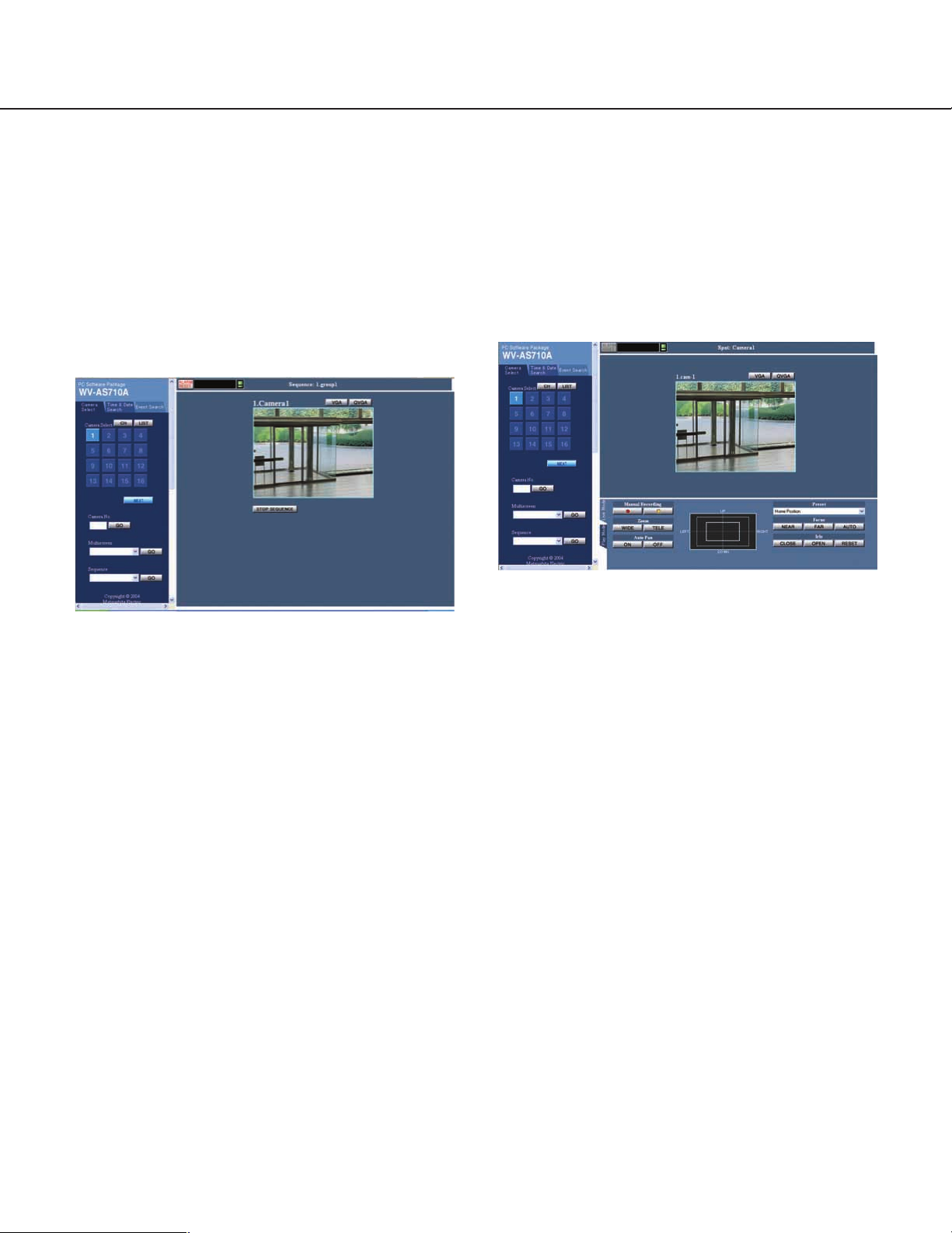
How to Use the Camera Page
To operate the "Camera Page", refer to the following. To display the "Camera Page", click one of the available camera buttons on the "TOP MENU" page.
Click a tab to change the operation menus.
Menu
"Live Mode"/"Play Mode" panel
"Camera Select" tab
Click this tab to display the "Camera Select "menu.
"Time & Date Search" tab
Click this tab to display the "Time & Date Search"
menu. Use this menu to search recorded pictures
stored in the network camera server by time and
date.
"Event Search" tab
Click this tab to display the "Event Search" menu.
Searching can be made by specifying detailed criteria to play back the event pictures.
Picture Display Area
The selected camera picture or playback picture is
displayed in this area.
Note: Live camera pictures will not be displayed even
when an available button is clicked, in the following
cases.
• When the network camera server stops delivering camera pictures temporarily. (The network
camera server stops delivering camera pictures
during "Camera Sleep Schedule". Refer to page
57 for further information.
Picture Display Area
• When IP addresses of cameras registered to
the network camera server are incorrect.
• When a camera registered to the network camera server is not connected.
• When the network camera server cannot
acquire camera pictures because of connection
trouble, malfunctioning of cameras, etc.
• Even if MPEG-4 Plug-in Software is not
installed on a PC, the network camera server
will deliver MPEG-4 camera pictures. (In this
case, this problem will be solved by downloading MPEG-4 Plug-in Software from the "TOP
MENU" page and installing it.) Refer to page 32
for further information.
"Live Mode"/"Play Mode" panel
"Live Mode" panel
Operate the selected camera with this panel in
the following case. Depending on cameras,
some of their functions are not available with
this panel.
• Recording camera pictures
• Preset function
• Panning, tilting, zooming and scanning
• Adjustment of focus and brightness
• Controlling auxiliary device of cameras
"Play Mode" panel
When "Live View & Recording" is selected as
the system type of the network camera server,
this panel is available. Users can operate this
panel to play recorded pictures stored in the
network camera server in various ways.
Notes:
• The available functions differ depending on
the models of connected cameras, and the
image format of pictures delivered by the
cameras.
• The "Live Mode" panel will be displayed
only when a camera picture is displayed in
the single screen. (The "Live Mode" panel is
not operable when the multiscreen or
sequence is displayed.)
13
Page 14
Operation
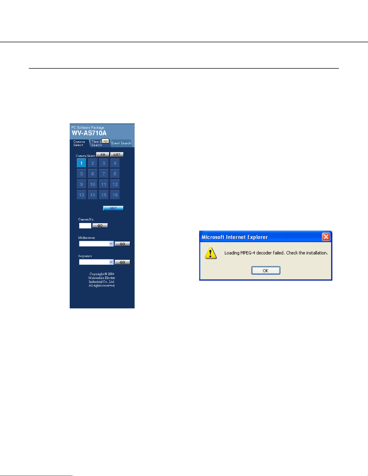
Camera Selection Menu
Use this menu to monitor live camera pictures. Depending on the setting of the network camera server, up to 16 live
camera pictures can be monitored simultaneously.
How to display the camera selection menu
Click the "Camera Select" tab.
[NEXT] / [PREV] buttons
Click these buttons to open the next page or previous page of "Camera Select" numbers in the button
form.
"Camera No." / [GO] button
Enter the desired camera number in the input box
next to this button, and click this button to display
the camera picture respective to the entered camera number in the picture display area.
Note: When a camera delivering camera pictures
in the MPEG-4 format is selected, the dialog
window below may be displayed.
[CH] button
Click this button to display "Camera Select" numbers in the button form. Use the [NEXT] and
[PREV] buttons to turn pages back and forth since
only up to 16 camera buttons can be displayed at a
time.
[LIST] button
Click this button to display "Camera Select" numbers and camera names in the list form. Click a
desired number in the list to view the live picture in
the picture display area.
"Camera Select" [1] – [64] (Live View & Recording)/
[1] – [128] (Live View Only)
Click a desired camera number to view the live picture in the picture display area.
14
This window will be displayed if the MPEG-4 Plugin Software is not installed to browse MPEG-4
motion pictures on a web browser. Refer to the
"MPEG-4 Plug-in Software Installation" on page 32.
"Multi-screen" / [GO] button
Select a multi-screen name from the pull-down
menu, and click this button to view the multi-screen
picture in the picture display area.
Note: An administrator is required to set the multi-
screen names and their camera combinations
in the administrator’s page beforehand.
"Sequence" / [GO] button
Select a sequence name from the pull-down menu,
and click this button to run a series of single screen
sequence in the picture display area.
Note: An administrator is required to set the
sequence names and their camera assignment
to steps in the "Administrator’s Page" beforehand.
Page 15
Live Picture Display Area
In the "Live Mode", the camera pictures are displayed in the single screen, the multi-screen comprising a maximum
of 16 splits, or the sequence.
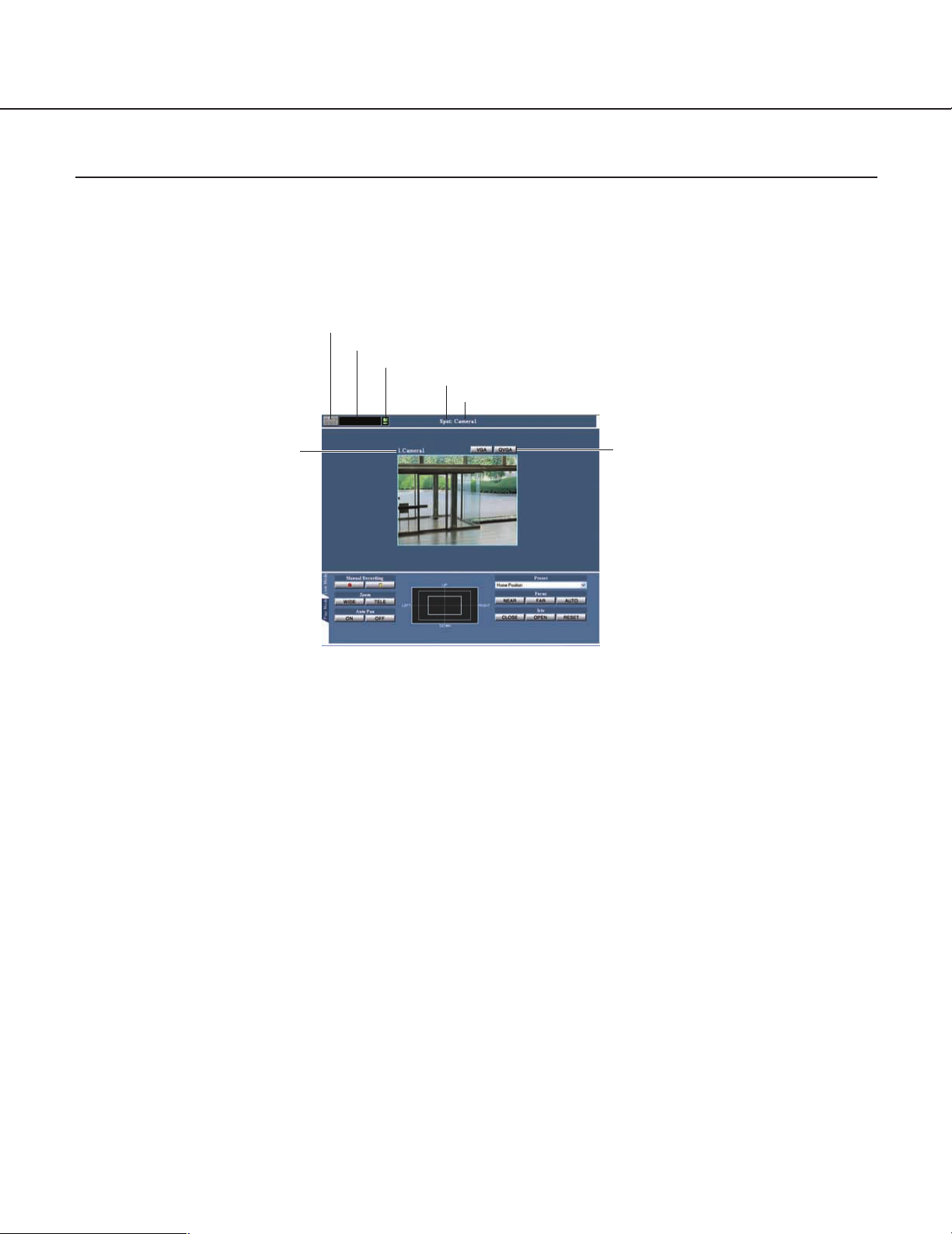
Live Single Screen
This page details about the single screen.
Alarm display
Recording status display
Screen mode display
Disk capacity warning
Camera No. display
Camera No., camera title display
Alarm display
This section indicates that an alarm arises on a
camera and/or the server. Click it to reset the alarm
and to display the "Event Search" menu on the left
of the window.
Recording status display
This section indicates that a camera is in recording.
Move the cursor to it to pop up a small window for
information on the camera number.
ALM: Alarm recording
SCH: Schedule recording
MAN: Manual recording
Disk capacity warning
This section warns you that the remaining disk
capacity for a camera connected to nears the end.
Move the cursor to it to pop up a small window for
information on the camera number.
Screen mode display
This section indicates the screen mode (Spot) in
which the picture is displayed.
Camera No. display
This section indicates the camera number whose
picture is displayed.
Screen size selection
Camera No., camera title display
This section indicates the camera number and title
whose picture is displayed.
Screen size selection [VGA]/[QVGA], [CIF]/[QCIF]
button
Select VGA or QVGA when JPEG format is applied
to the pictures, or select CIF or QCIF when MPEG4 is applied.
15
Page 16
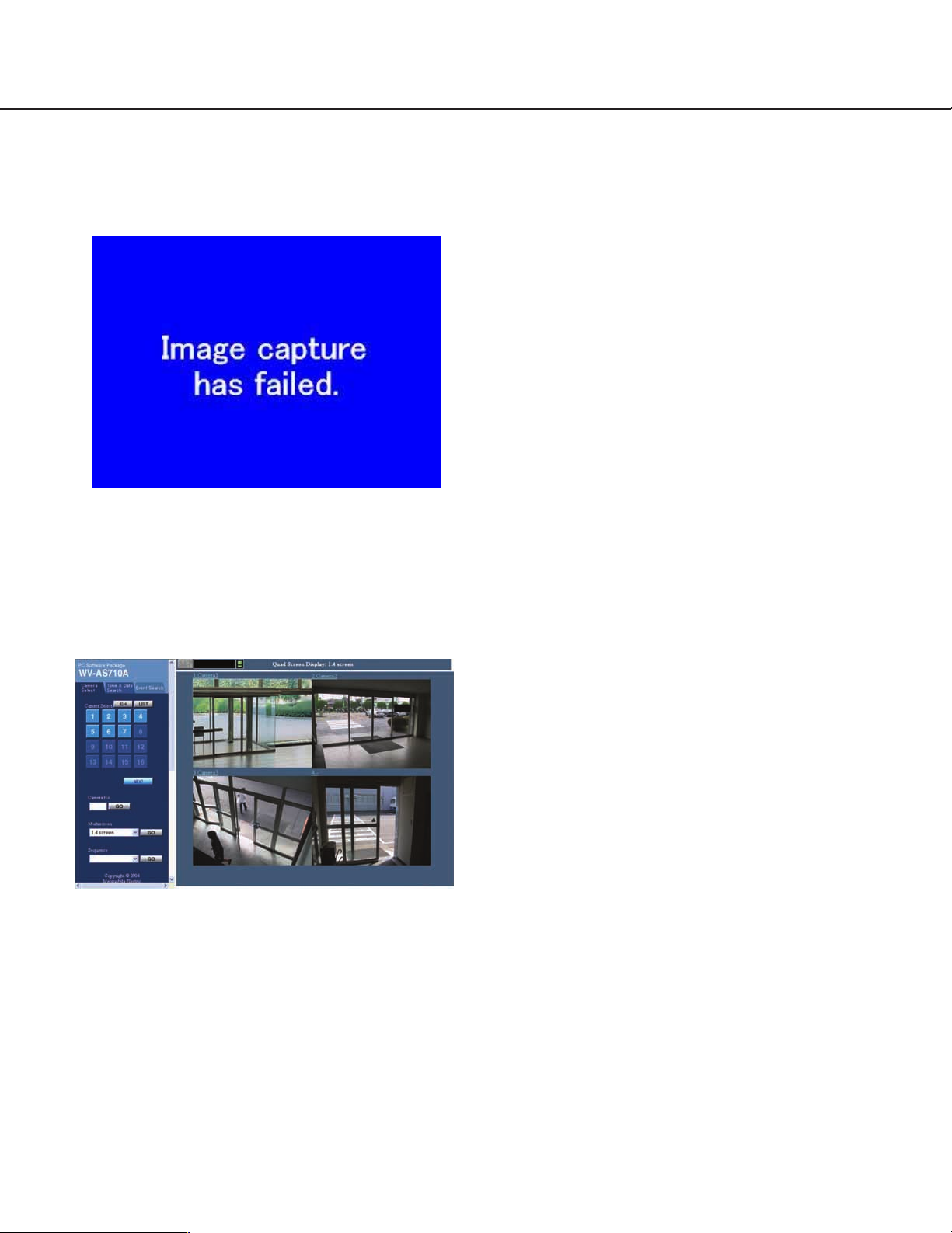
Operation
When failure to acquire a camera picture occurred:
When the network camera server could not acquire
a camera picture, the picture below will be displayed.
It is possible to send an e-mail to an addresses
registered in advance to notify of this failure.
Live Multi Screen Display
Alarm indicator
This section indicates that an alarm arises on a
camera and/or the server. Click it to reset the alarm
and to display the "Event Search" menu on the left
of the window.
Recording status indicator
This section indicates that a camera is in recording.
Move the cursor to it to pop up a small window for
information on the camera.
ALM: Alarm recording
SCH: Schedule recording
MAN: Manual recording
Disk capacity warning
This section warns you that the remaining disk
capacity for a camera nears the end. Move the cursor to it to pop up a small window for information
on the camera number.
Screen mode
This section indicates the screen mode (number of
split) in which the picture is displayed.
Multiscreen title
This section indicates the multiscreen title whose
picture is displayed.
Camera No., camera title
This section indicates the camera numbers and
camera titles when a quad screen is displayed.
When split to 9 or 16, this section indicates only
camera numbers. Move the cursor to a split section
to pop up the respective camera title. To enlarge a
split section to a single display, click on the section.
Note: Enter camera titles in the administrator’s
page beforehand.
A quad, 9, or 16-split multiscreen picture can be displayed by selecting a multiscreen name from the pulldown menu and clicking the [GO] button in the main
operation panel. While a multi-screen is displayed,
manual recording and camera control will be disabled
since the live-mode panel disappears.
Note: An administrator is required to set the following
in the administrator’s page.
• Specify the setting of pull-down menu display
for multiscreen to ON in the "System
Properties" menu.
• Specify the properties of multiscreen groups.
16
Page 17
Live Sequence Display
A series of single camera pictures can be displayed by
selecting a sequence name from the pull-down menu
and clicking the [GO] button in the "Camera Select"
panel.
Note: An administrator is required to set the following
in the administrator’s page.
• Specify the setting of pull-down menu display for
sequence to ON in the "System Properties" menu.
• Specify the properties of sequence groups.
Camera No., camera title
This section indicates the camera number and
camera title whose picture is displayed.
Note: Enter camera titles in the administrator’s
page beforehand.
[STOP SEQUENCE] button
Click this button to stop the sequence. While stopping the sequence, the live mode panel appears.
Alarm indicator
This section indicates that an alarm arises on a
camera and/or the server. Click it to reset the alarm
and to display the "Event Search" menu on the left
of the window.
Recording status indicator
This section indicates that a camera is in recording.
Move the cursor to it to pop up a small window for
information on the camera number.
ALM: Alarm recording
SCH: Schedule recording
MAN: Manual recording
Disk capacity warning
This section warns you that the remaining disk
capacity for a camera nears the end. Move the cursor to it to pop up a small window for information
on the camera number.
Screen mode
This section indicates the mode (sequence) being
displayed.
Sequence title
This section indicates the sequence title whose picture is displayed.
[START] button
Click this button to resume the sequence.
[PREV] button
Click this button to go back the sequence by one
step.
[NEXT] button
Click this button to forward the sequence by one
step.
17
Page 18
Operation
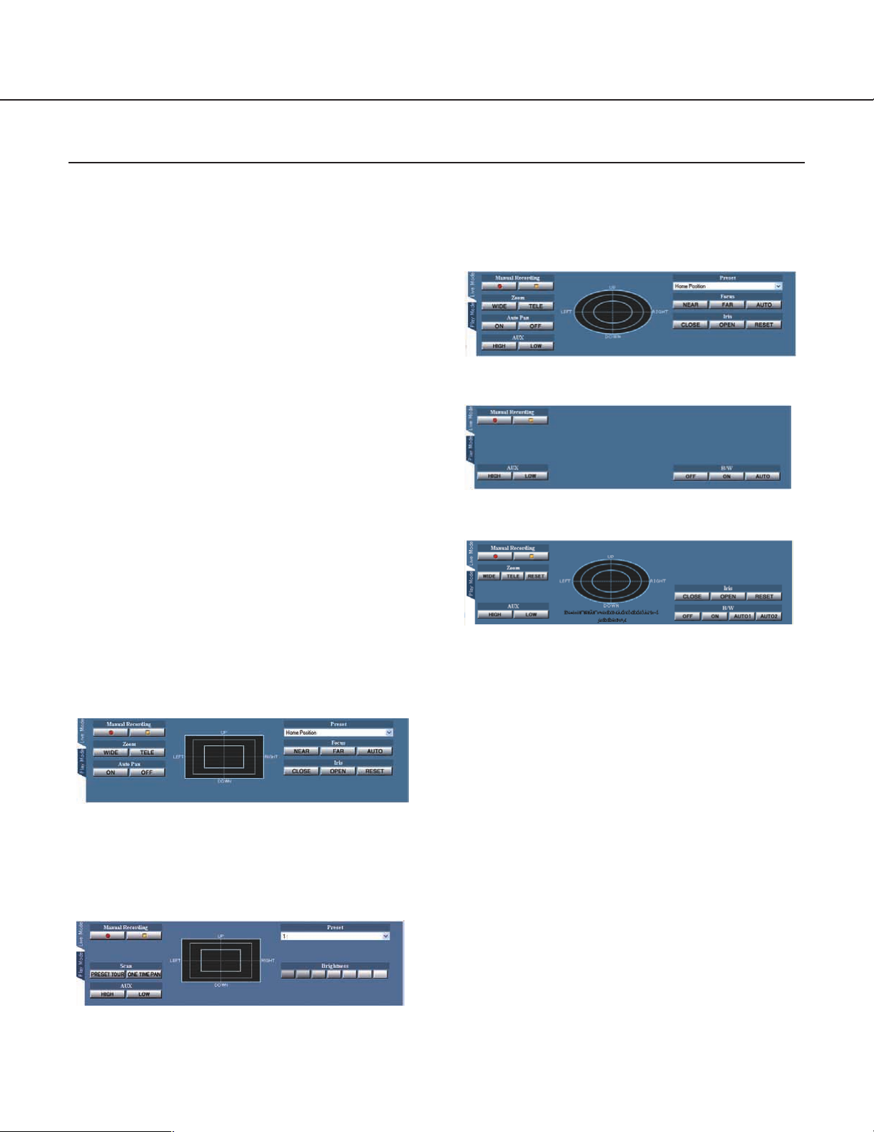
Live Mode Panel
The live mode panel contains the buttons to control the selected camera. (When a multiscreen is displayed, this
panel is not displayed.) The buttons displayed in the live mode panel differ depending on the model of the selected
camera.
How to display the live mode panel
The live mode panel will be displayed by one of the following operations:
• Clicking one of the "Camera Select" buttons in the
camera selection menu.
• Clicking the "Live Mode" tab in the live mode panel.
• Clicking the [Sequence Stop] button while running
a sequence
About the user authentication dialog window:
The authentication dialog window will be displayed
when a user tries to access a camera which the user is
not allowed to access. In this case, cancel the operation or enter a valid user name and password to be
allowed to access and operate the selected camera.
About camera control:
It is impossible to operate the camera if another user
having a higher or the same priority is currently operating it (it is possible to access the selected camera only
to view live pictures.)
When the selected camera is connected by the network interface unit WJ-NT104:
Note: The operable buttons will depend on the fea-
tures of the camera connected by the WJ-NT104.
When the selected camera is a WV-NS324:
When the selected camera is a WV-NP472:
When the selected camera is a WV-NW474:
Manual Recording ("Live View & Recording")
Click the [●] button to record the currently monitored
camera picture on the hard disk of the network camera
server. If the camera picture is recorded in the JPEG
format, the camera picture will be recorded at 1 fps
(JPEG) until the [■] button is clicked. If the camera picture is recorded in the MPEG-4 format, the camera picture will be recorded at the transmission rate of the
camera until the [■] button is clicked. The "Priority" of
manual recording is "3" and pictures recorded by manual recording will be stored in the protected disk space.
When the selected camera is a WV-NM100:
18
Note: When pictures are recorded in the JPEG format,
recording interval may differ as below.
• If a recording whose priority is higher than the
manual recording priority (for example, alarm
recording (priority: 2) or a schedule recording
whose priority is set to "1" or "2" and whose
recorded pictures are set to be stored in the
protected disk space), is performed during manual recording, pictures will be recorded at the
recording interval of the recording whose priority is the highest.
Page 19

• Depending on the setting of "Minimum Access
Interval/Maximum Frame Rate", the recording
interval will be different from the examples
above.
Refer to page 52 for further information.
To stop recording, click the [■] button.
Note: Manual recording will be stopped in the following
cases. It is impossible to stop recording by closing
the window of a web browser or by shutting down
the web browser.
• When another user accessing the camera while
it is recording clicks the [■] button.
• When an administrator stops or restarts the
WV-AS710A (Recording will not resume automatically after restart.)
Zoom
Click the [WIDE] button or the [TELE] button to
control the zoom lens of the selected camera.
Note: Even if the [WIDE] button or the [TELE] but-
ton is kept pressed, the camera will not keep on
zooming.
Preset
Select a preset position to move the camera to the
selected preset position. Preset position numbers 1
to 64 and home position are available for this function. The available preset position numbers differ
depending on the model of the selected camera as
below:
A camera connected by the WJ-NT104: 1 to 64
WV-NM100: 1 to 8
WV-NS324: 1 to 16
Notes:
• The preset function is a function of the camera,
not of the network camera server. If the preset
position is not set on the camera, this function
is not available.
• It is available only when a Panasonic’s combination camera is connected and selected.
Pan/Tilt pad
Clicking a desired direction in the pan/tilt pad will
move the camera up, down, right, or left if the camera is mounted on a pan/tilt table. Moving speed
and distance differ depending on the model of the
selected camera.
When the selected camera is delivering JPEG:
When one of the edges (top, bottom, left, right) of
the camera picture is clicked, the camera pans or
tilts toward the clicked direction. (When browsing
MPEG-4, panning and tilting by clicking on the
camera picture is not possible.) The range of panning and tilting by one click differs depending on
the distance between the center point and the
clicked point. For example, if you click the right
edge, the camera pans widely toward the right
side. Tilting is performed in the same way as panning. The camera will not move if the clicked point
is just around the center point.
Notes:
• Pan/tilt move is possible only when one of the
following cameras is selected.
• WV-NS324
• WV-NM100 (only when JPEG delivering
mode)
• Combination cameras connected to WJNT104 data multiplex unit
• In case of WV-NW474, pan/tilt move is available only when TELE is selected for zoom.
• Continuous pan/tilt move is not possible by
pressing and holding a point in the picture or
the pad when the selected camera is a WVNM100 or connected to a WJ-NT104 multiplex
unit. Repeat clicking as necessary.
Auto Pan
Click the [ON] button to start the AUTO functions
set on the cameras (AUTO PAN, SEQ, SORT,
PATROL and so on). The available functions differ
depending on the settings of the cameras. Refer to
the operating instructions of the cameras for further
information. The way of panning differs depending
on the model of the selected camera.
Click the [OFF] button to stop the AUTO functions.
Clicking other buttons (except the [●] button or the
[■] button of "Manual Recording") also stops the
AUTO functions.
Note: Be sure to set up the auto functions on the
camera. Otherwise, these functions will not
work.
19
Page 20

Operation
Scan
When the [PRESET TOUR] button is clicked, the
camera starts touring the preset position number 1
to 8 in numerical order and stops automatically.
When the [ONE TIME PAN] button is clicked, the
camera starts panning once to the right end and
once to the left end, and then stops automatically.
AUX
An auxiliary device connected to the AUX terminal
on the camera can be controlled. Select [HIGH] or
[LOW] to match the specifications of the connected
device.
Focus
Click these buttons to adjust focusing.
Click the [NEAR] button to focus on a closer object.
Click the [FAR] button to focus on a farther object.
Click the [AUTO] button to focus on an object in the
center of the displayed picture.
Note: Even if the [NEAR] button or the [FAR] but-
ton is kept pressed, the camera will not keep on
focusing.
Brightness
Click these buttons to adjust the brightness of the
camera picture.
Clicking the left side buttons makes the camera
picture darker and clicking the right side buttons
makes the camera picture brighter.
"Play Mode" tab
Click this tab to switch from the "Live Mode" to the
"Play Mode" manually.
B/W
This setting determines whether the camera outputs the picture of color or of black-and-white.
[ON]: B/W picture is output.
[AUTO1]: Color pictures change to B/W when the
input light becomes dark, and vice versa.
[AUTO2]: Same as above, except brighter switch-
ing point.
[OFF]: Color picture is output.
Note: Refer to the operating instructions of the
camera for details.
Iris
Click these buttons to adjust the iris. Generally, to
shoot images with a clear background or to shoot
in bright locations, the iris should be closed.
Click the [OPEN] button to open the iris, so that the
depth of field will be shallower.
Click the [CLOSE] button to close the iris, so that
the depth of field will be deeper.
Click the [RESET] button to return to the default
depth of field.
Note: Even if the [OPEN] button or the [CLOSE]
button is kept pressed, the iris will not keep on
opening or closing.
20
Page 21
Playback of Recorded Pictures
When "Live View & Recording" is selected as the system type of the network camera server, the following recorded
pictures will be stored in the allocated disk space of the network camera server.
• Manually recorded camera pictures by clicking the [●] button of "Manual Recording" on the "Live Mode" panel.
• Automatically recorded camera pictures when an alarm occurred at a camera site. (Set by an administrator)
• Automatically recorded camera pictures by the setting of the recording schedule. (Set by an administrator)
■ How to play back pictures
Play recorded pictures stored in the network camera
server as follows:
1. Click the "Time & Date Search" tab or the
"Event Search" tab.
"Time & Date Search":
Search the server for the recorded pictures by designating a camera number, time and date.
"Event Search":
Search for the events by designating detailed conditions such as event types that is not in the "Time
& Date Search".
2. Enter the conditions for searching recorded
pictures, and then click the [SEARCH] button.
The search result will be displayed in the main control frame.
3. Click a link text or a thumbnail from the results.
The playback of the events will start. Users can
operate buttons on the play mode panel to play
recorded pictures.
Even an event picture that has started recording, it
will be played back when searched and clicked in
the search results.
A multi-screen will be played back if the search is
carried out while the PC displays a multi-screen
that includes the camera to be searched.
When playback of the recorded picture finishes, the
next record will be played back.
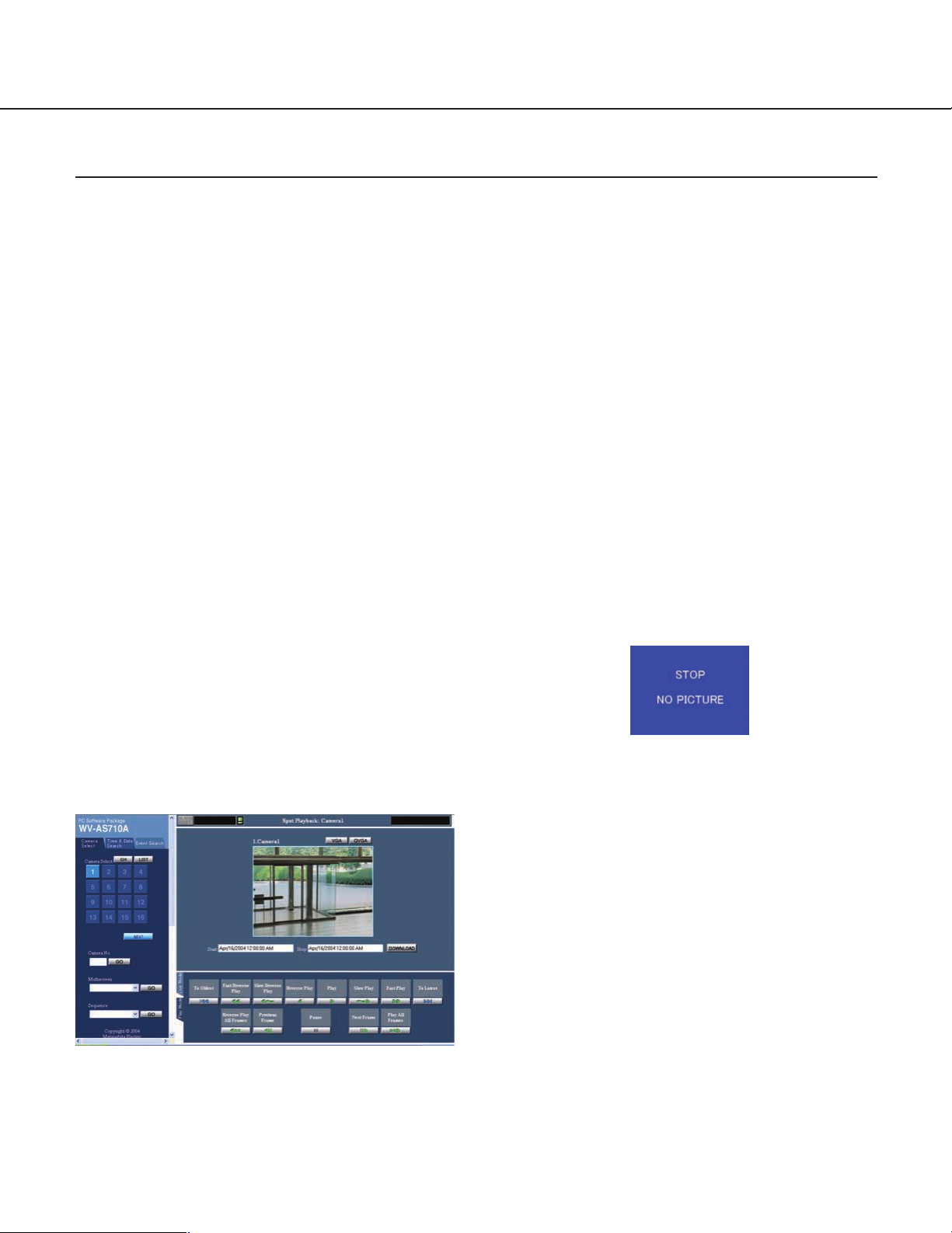
When starting playback without selecting a link text
or a thumbnail from the result list of the "Event
Search" or "Time & Date Search", the last frame of
the latest recorded picture is played, and then the
picture that says "STOP NO PICTURE" will be displayed.
About playback of recorded pictures:
Playback of recorded pictures is possible only when
"Live View & Recording" is selected as the system
type of the network camera server.
When a user who is authenticated as a "camera-inoperable" user clicks a button in the play mode control
frame, the user authentication dialog window will be
displayed. In this case, perform the authentication as a
"camera-operable" user, or click the [Cancel] button in
the user authentication dialog window.
21
Page 22
Operation
Downloading Recorded Picture
It is possible to download the recorded pictures onto a
PC by designating the start time and stop time.
1. Play a recorded picture and confirm the date
and time to download.
2. Enter the desired time for the "Start time" and
"Stop time".
It is possible to download recorded picture of up to
30 minutes. When playback starts, the start time of
the recorded picture will be displayed in the "Start
time" input box and the "Start time" plus 30 minutes
will be displayed in the "Stop time" input box.
3. Click the [DOWNLOAD] button.
Follow the displayed instructions. It will take several minutes for the network camera server to prepare the recorded picture to be downloaded. Do
not click any buttons until the network camera server completes preparation.
When download has been completed, the downloaded file will be saved as a self-extracting executable file (file extension: .exe). A file name
includes the start time of the downloading, e.g.
IMG20040626212557 indicates that it was started
downloading at 21:25:57 on June 26 2004.
When pictures delivered from a camera are in the
JPEG format, JPEG files and html documents will
be downloaded as a self-extracting executable file.
When pictures delivered from a camera are in the
MPEG-4 format, MPEG-4 files (file extension:
.mg4) and an index file (file extension: .idx) will be
downloaded as a self-extracting executable file.
Play Downloaded Recorded Picture
To play the downloaded recorded picture, do the following.
To play JPEG
1. Move the downloaded self-extracting executable
file to the desired folder, and then double click it.
When the downloaded self-extracting file is double
clicked, JPEG files (file extension: .jpg) and html
documents used as a browser (index.html, thumb
html, play.html) will be uncompressed in the selected folder.
Notes:
• Browse the uncompressed JPEG files using the
uncompressed html document (index.html).
• When the size of the picture delivered from the
camera is 640 x 240 pixels, some image editing
software such as "Paint" will display the picture
in the half vertical size.
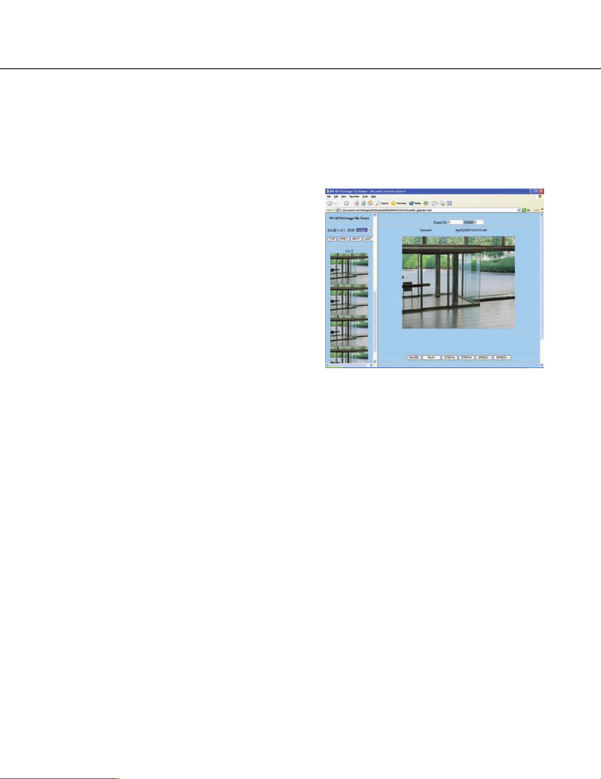
2. Display the index.html using a web browser.
The web page below will be displayed.
SKIP: Select a number of thumbnail display pages to
be skipped.
TOP: Click this button to go back to the top page on
the left frame.
PREV: Click this button to display the previous page.
The displayed page depends on the selected page
number for "SKIP".
NEXT: Click this button to display the next page. The
displayed page depends on the selected page
number for "SKIP".
LAST: Click this button to go to the last page.
Frame No.: Click this button to display the currently
browsed frame number.
SPEED: Click this button to display the playback
speed. When playing in reverse, the playback
speed will be displayed with a minus (–).
STEP <<: Click this button to go back to a previous
frame and pause.
PLAY: Click this button to start playback.
STEP >>: Click this button to go to the next frame and
pause.
SPEED –: Click this button to slow down the playback
speed one step (–1).
PAUSE: Click this button to pause the playback.
SPEED +: Click this button to speed up the playback
speed one step (+1).
22
Page 23
To play MPEG-4
To play the downloaded recorded picture in the
MPEG-4 format, it is required to install the MPEG-4
Player on the PC in advance.
Note: Downloading the MPEG-4 Player is possible
from the "TOP MENU". Refer to the "Installation of
the MPEG-4 Player" on page 33.
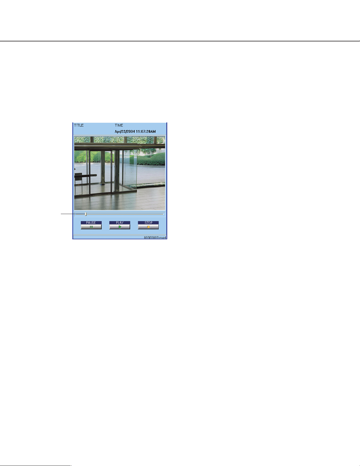
Slider
3. Select "File" - "Open" from the menu bar, and
then select an uncompressed MPEG-4 file to
open it.
File Menu
Open: Select an MPEG-4 file to be played.
Close: Quit the MPEG-4 Player.
Help Menu
About: Displays the MPEG-4 Player version.
Slider: Move this slider to the desired point of play-
back using the mouse.
Pause: Pauses the playback. Click this button
again to resume the playback.
Play: Starts the playback.
Stop: Stops the playback.
1. Move the downloaded self-extracting
executable file to the desired folder, and then
double click it.
When the downloaded self-extracting file is double
clicked, MPEG-4 files (file extension: .mg4) and an
index file which includes information about the
recording time, etc. (file extension: .idx) will be
uncompressed in the selected folder.
Note: Place the MPEG-4 files and the index file in
the same folder. If they are placed in different
folders, or the index file is deleted, it may be
impossible to play the MPEG-4 files.
2. Start up the MPEG-4 Player.
When the MPEG-4 Player is installed, the MPEG-4
Player will be added to the "Start" menu in
Windows.
In Windows 2000: [Programs] - [WV-AS710
MPEG-4 Player] - [WV-AS710 MPEG-4 Player]
In Windows XP: [All Programs] - [WV-AS710
MPEG-4 Player] - [WV-AS710 MPEG-4 Player]
23
Page 24
Operation
Searching Menu
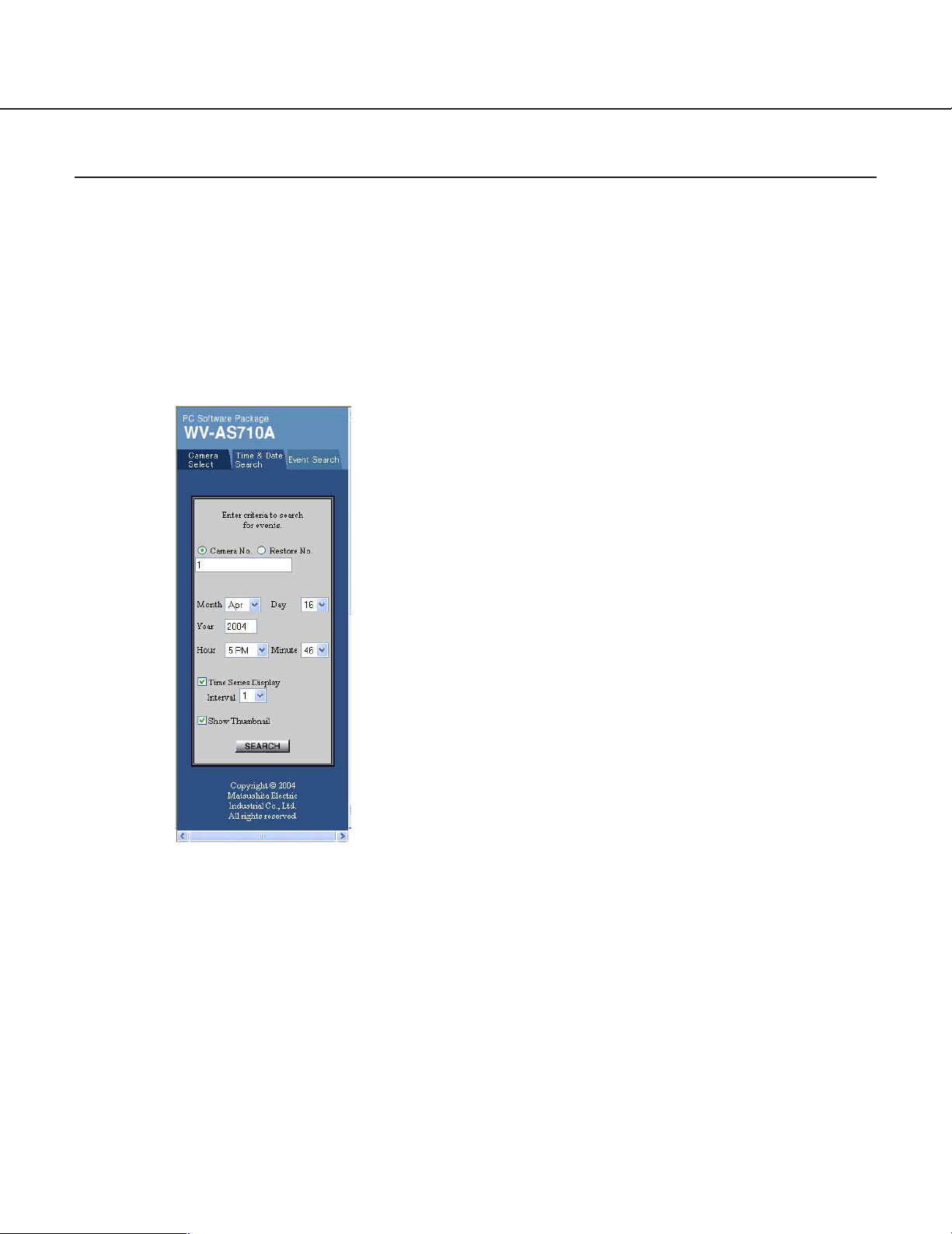
"Time & Date Search"
Search for the recorded pictures saved in the network camera server by designating a camera number, date and time.
How to display the "Time & Date Search"
Click the "Time & Date Search" tab.
Note: The authentication dialog window will be displayed when a user tries to access a camera which the user is not
allowed to access. In this case, cancel the operation or enter a valid user name and password to be allowed to
access and operate the selected camera.
Notes:
• Restore data are picture data that an administrator performed restoration on the
"Administrator’s Page".
• Only level 1 users can search for the restored
data.
• When a camera number without disk space
allocation for recorded pictures, or a camera
number that the user is not allowed to access is
entered, an error message will be displayed.
Year
Enter the year to be searched in this input box with
4 digits. An error message will be displayed if the
[SEARCH] button is clicked when this input box is
blank.
Month/Day
Select the month and day to be searched .
Hour/Minute
Select the hour and minute to be searched .
Time Series Display/Interval (minute)
Check this box and select an interval (minute)
when searching for a single camera chronologically
[Camera No.] radio button
Check this button to search for recorded camera
pictures.
[Restore No.] radio button
Check this button to search for restored picture
data.
Number input column
Enter the numbers for the recorded camera pictures or restored data you wish to search. When
more than one is to be searched, separate numbers with a comma (,). When consecutive numbers
are to be searched, put a hyphen (-) between the
start number and the end number. When the pictures of all cameras are to be searched, enter an
asterisk (*).
with the specified interval. A maximum of 16 data
will be displayed.
Show Thumbnail
Check this box to display a list of results with the
respective pictures in small scale. The MPEG-4
recorded pictures will not be displayed with the
thumbnail in the list of results.
[SEARCH] button
Click this button to start searching.
24
Page 25
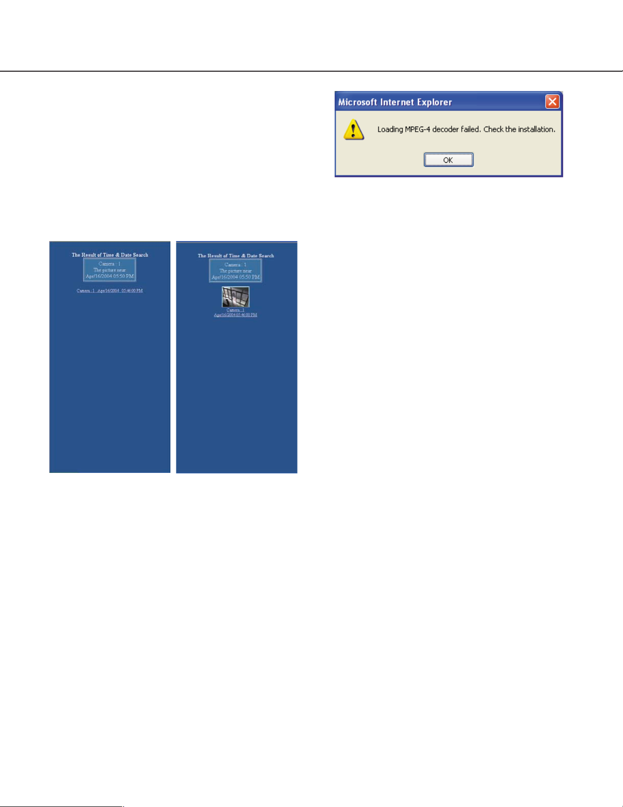
"Time & Data" Search Results
After the [SEARCH] button is clicked, the results
will be displayed in the window.
Up to 64 data will be displayed. For time order
search, a maximum of 16 data will be displayed.
Note: When the time on the clocks of the network
camera server and the PC do not match,
searches will not performed correctly.
Result List (Text) Result List (Thumbnail)
This window will be displayed if the MPEG-4 Plug-in
Software is not installed to browse MPEG-4 motion
pictures on the web browser. Refer to the "MPEG-4
Plug-in Software Installation" on page 32.
Search condition display
Camera numbers and time-and-date are displayed
that were specified in the search window.
Search result display
The search results are listed in the text form or
thumbnail form with the camera number and date&-time.
Click a text line or a thumbnail to play back the
recorded pictures from the searched point. A multiscreen will be played back if the search is performed while the PC displays a multi-screen that
includes the camera to be searched.
Notes:
• When pictures are recorded in the MPEG-4 format, the thumbnails appear only with text, not
with a still picture.
• When pictures are recorded in the MPEG-4 format, the dialog window below may be displayed
25
Page 26
Operation
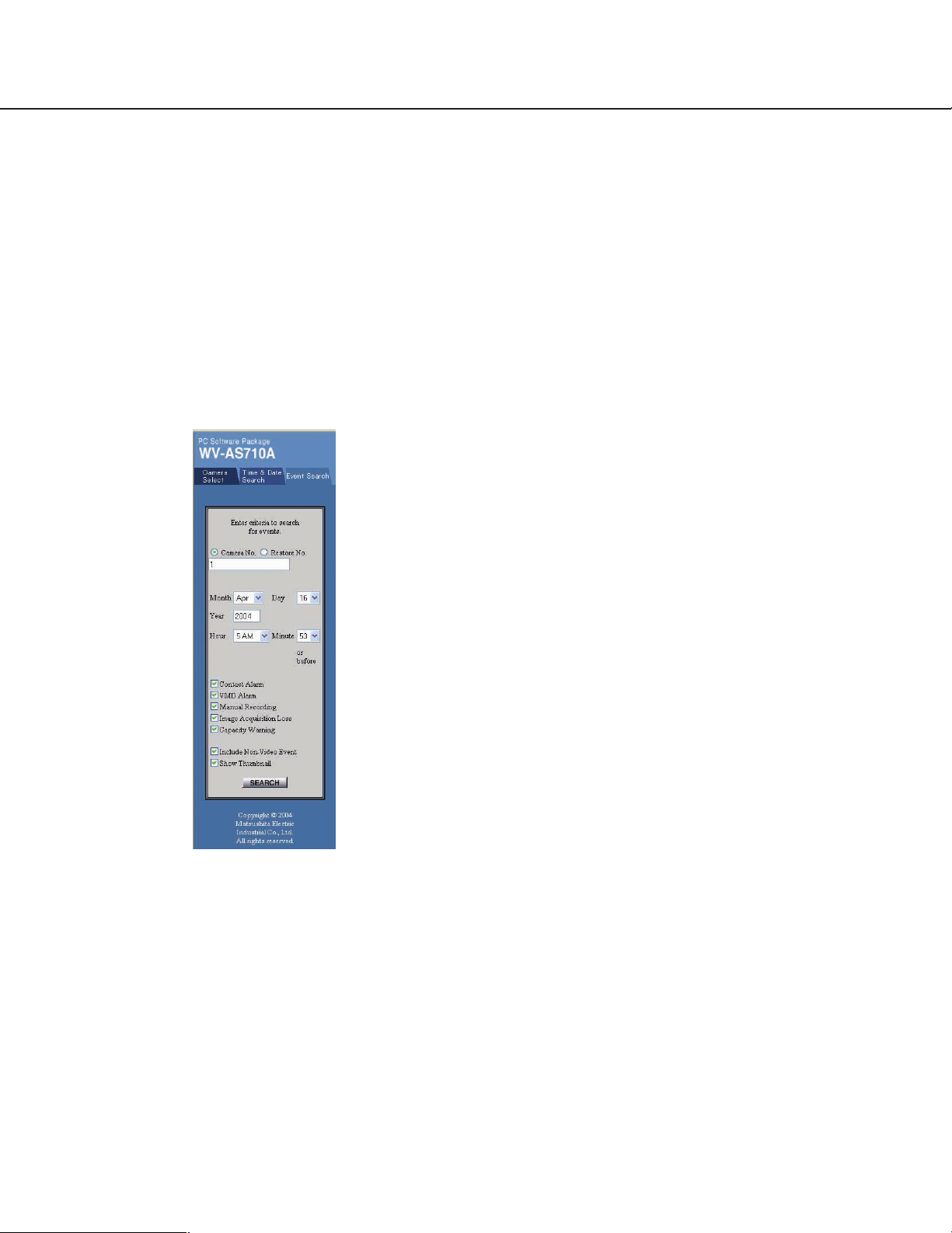
"Event Search"
Search for the recorded pictures saved in the network
camera server by detailed criteria such as time-anddate, camera number, and event type.
How to display the "Event Search"
Click the "Event Search" tab.
Note: The authentication dialog window will be dis-
played when a user tries to access a camera which
the user is not allowed to access. In this case, cancel the operation or enter a valid user name and
password to be allowed to access and operate the
selected camera.
[Camera No.] radio button
Check this button to search for recorded camera
pictures.
[Restore No.] radio button
Check this button to search for restored picture
data.
Number input column
Enter the numbers for the recorded camera pictures or restored data you wish to search. When
more than one is to be searched, separate numbers with a comma (,). When consecutive numbers
are to be searched, put a hyphen (-) between the
start number and the end number. When the pictures of all cameras are to be searched, enter an
asterisk (*).
Notes:
• Restore data are picture data that an administrator performed restoration on the
"Administrator’s Page".
• Only level 1 users can search for the restored
data.
• When a camera number without disk space
allocation for recorded pictures, or a camera
number that the user is not allowed to access is
entered, an error message will be displayed.
Year
Enter the year to be searched in this input box with
4 digits. An error message will be displayed if the
[SEARCH] button is clicked when this input box is
blank.
Month/Day
Select the month and day to be searched.
Hour/Minute
Select the hour and minute to be searched.
Contact Alarm
Check this box to search camera pictures recorded
when a contact alarm occurred at a camera site.
VMD Alarm
Check this box to search camera pictures recorded
when motion was detected by the video motion
detection function of cameras.
Manual Recording
Check this box to search camera pictures recorded
manually using "Manual Recording" on the "Live
Mode" panel.
Include disk capacity warning
Check this box to search for the time-and-date of
issued warnings that the remaining disk space for a
camera nears the end.
Image Acquisition Loss
Check this box to search events including events in
which camera pictures were not sent because of
connection trouble, network trouble, malfunctioning
of devices, etc.
Include Non-Video Event
Check this box to search all events near the
entered time and date, even events whose recorded pictures have already been deleted from the
network camera server, or events without recordings such as an image acquisition loss.
26
Page 27
Show Thumbnail
Check this box to display a list of results with the
respective pictures in small scale. The MPEG-4
recorded pictures will not be displayed with the
thumbnail in the list of results.
[SEARCH] button
Click this button to start searching.
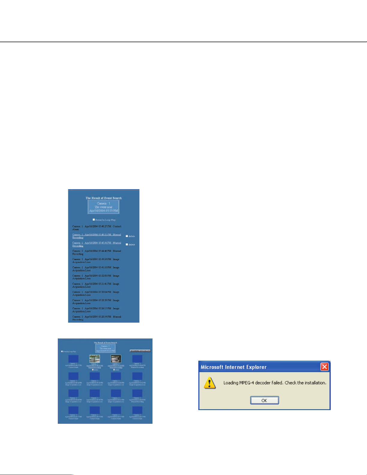
"Event Search" Results
After the [SEARCH] button is clicked, the results of
up to 16 data will be displayed in the window.
Note: When the time on the clocks of the network
camera server and the PC do not match,
searches will not performed correctly.
Result List (Text)
Result List (Thumbnail)
Search condition display
Camera numbers and time-and-date are displayed
that were specified in the search window.
[RECORDING DATA DELETE] button
Click this button to erase picture data of the events
whose image delete check box is active. Only level
1 users are allowed to operate this button.
Image delete check box
Check this box to register the deletion of the picture
data of the event. The data will be erased when the
[RECORDING DATA DELETE] button is clicked,
although the event log will remain.
Search result display
The search results are listed in the text form or
thumbnail form with the camera number and timeand-date.
Click a text line or a thumbnail to play back the
recorded pictures from the searched point.
Pictures will not be played back in the following
cases: the picture data were erased, the event
failed in image acquisition, or the event was
warned by shortage of disk capacity since there is
no picture data.
A multi-screen may be played back if the search is
carried out while the PC displays a multi-screen
that includes the camera to be searched. As an
exception, a single picture will be played when the
[Loop Play within Event] is checked.
[PREV-n]/[NEXT-n] button
Click this button to jump to the specified-number
previous or the next event.
[LATEST] button
Click this button to jump to the latest event.
Notes:
• When pictures are recorded in the MPEG-4 format,
the thumbnails appear only with text, not with a still
picture.
• When pictures are recorded in the MPEG-4 format,
the dialog window below may be displayed.
[Event In Loop Play] check box
Check this box to enable the playback of an event
to repeat.
This window will be displayed if the MPEG-4 Plugin Software is not installed to browse MPEG-4
motion pictures on the web browser. Refer to the
"MPEG-4 Plug-in Software Installation" on page 32.
27
Page 28
Operation
Play Picture Display Area
Playback pictures can be displayed in a single (spot), quad-split, 9-split or 16-split screen.
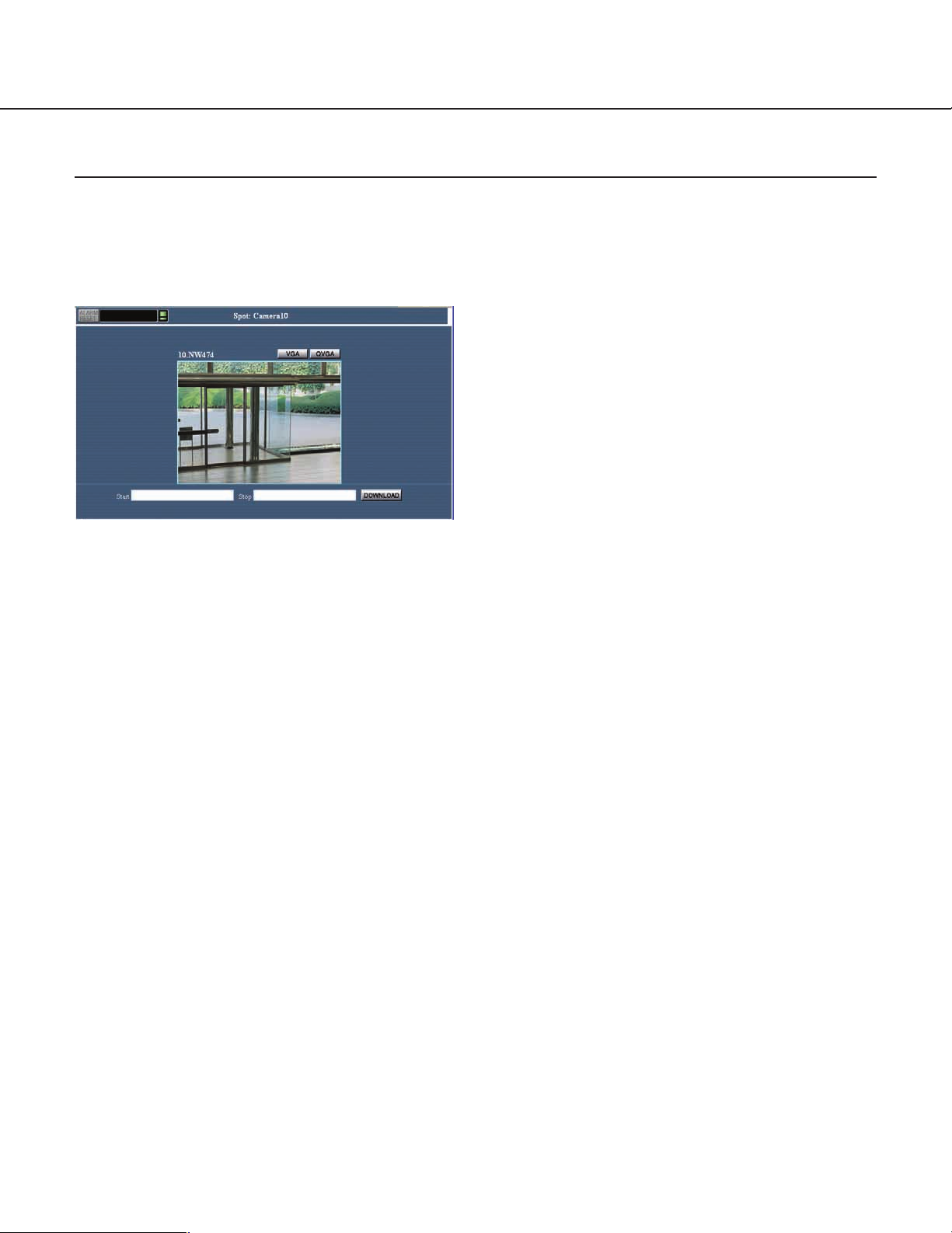
Spot Playback Screen
This page describes about the spot playback screen.
Camera No. display
This section indicates the camera number whose
picture is displayed.
Recorded time display
This section indicates the time that the playback
picture was recorded. An asterisk will precede the
time display when the summer time was applied to
the recording.
Camera No., camera title display
This section indicates the camera number and title
whose picture is displayed.
Note: An administrator is required to enter camera
Alarm display
This section indicates that an alarm arises on a
camera and/or the server. Click it to reset the alarm
and to display the event search window on the left
of the screen.
Recording status display
This section indicates that a camera is in recording.
Move the cursor to it to pop up a small window for
information on the camera number.
ALM: Alarm recording
SCH: Schedule recording
MAN: Manual recording
Disk capacity warning
This section warns you that the remaining disk
capacity for a camera nears the end. Move the cursor to it to pop up a small window for more information on the camera number.
Screen mode display
This section indicates the screen mode (Spot) in
which the picture is displayed.
Screen size selection [VGA]/[QVGA], [CIF]/[QCIF]
button
[Start] time, [End] time, [Download] button
titles in the administrator’s page beforehand.
Select VGA or QVGA when JPEG format is applied
to images, or select CIF or QCIF when MPEG-4
format is applied.
The start time is specified when an event in the
search window is clicked. On the other hand, the
end time becomes 30 minutes behind from the start
time at first.
Each of the start time and end time can be manually entered for the desired range within 30 minutes.
Click the download button to acquire the image
data from the server to a PC.
Note: For reference, a hard disk space of 100 MB
on a PC is required to download image data of
30 minutes playback, though this may depend
on the format.
28
Page 29
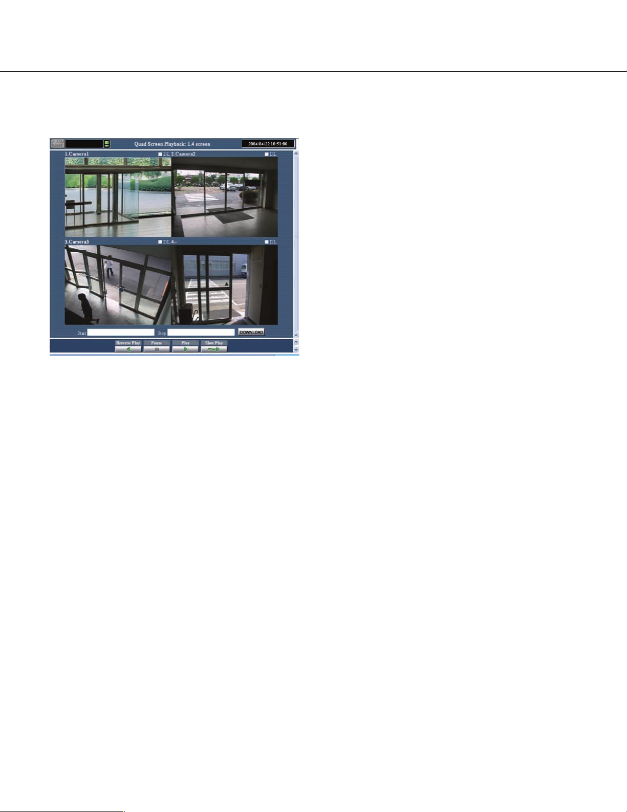
Multiscreen Playback Screen
This page describes about the multiscreen.
Alarm display
This section indicates that an alarm arises on a
camera and/or the server. Click it to reset the alarm
and to display the event search window on the left
of the screen.
Recording status display
This section indicates that a camera connected to
the network server starts recording. Move the cursor to it to pop up a small window for information
on the camera number.
ALM: Alarm recording
SCH: Schedule recording
MAN: Manual recording
Disk capacity warning
This section warns you that the remaining disk
capacity for a camera connected to the network
server nears the end. Move the cursor to it to pop
up a small window for more information on the
camera number.
Screen mode display
This section indicates the screen mode (4, 9, 16) in
which the picture is displayed.
Multiscreen name display
This section indicates the multiscreen group name
whose picture is displayed.
Recorded time display
This section indicates the time that the playback
picture was recorded. An asterisk will precede the
time display when the summer time was applied to
the recording.
Camera No., camera title
This section indicates the camera numbers and
camera titles when a quad screen is displayed.
When split to 9 or 16, this section indicates only
camera numbers. Move the cursor to a split section
to pop up the respective camera title. To enlarge a
split section to a single display, click on the section.
Note: An administrator is required to enter camera
titles in the administrator’s page beforehand.
Multiple download check boxes
Check the boxes of the images you wish to down
load, and specify the start and end times, finally
click the download button.
[Start] time, [End] time, [Download] button
The start time is specified when an event in the
search window is clicked. On the other hand, the
end time becomes 30 minutes behind from the start
time at first.
Each of the start time and end time can be manually entered for the desired range within 30 minutes.
Click the download button to acquire the image
data from to a PC.
Note: For reference, a hard disk space of 100 MB
on a PC is required to download image data of
30 minutes playback, though this may depend
on the format.
29
Page 30
Operation
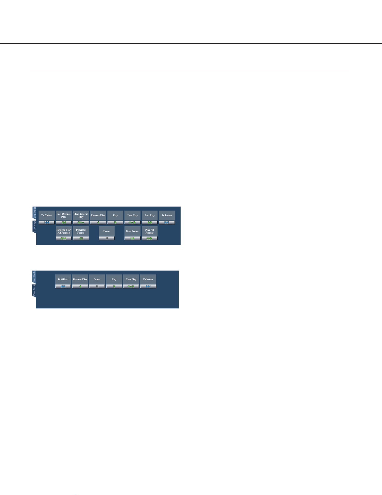
Play Mode Panel
The play mode panel contains the buttons to play recorded pictures in various ways.
How to Display the Play Mode Panel
The play mode panel will be displayed when the
desired recorded picture in the search results is
clicked, or when the "Play Mode" tab is clicked.
Note: The authentication dialog window will be dis-
played when a user tries to access a camera which
the user is not allowed to access. In this case, cancel the operation or enter a valid user name and
password to be allowed to access and operate the
selected camera.
Play Mode Panel (JPEG):
Play Mode Panel (MPEG-4):
To Latest (only for single screen)
Click this button to go to the latest picture of all
recorded pictures in the network camera server.
To Oldest (only for single screen)
Click this button to go to the oldest picture of all
recorded pictures in the network camera server.
Fast Reverse Play (only for JPEG single screen)
Click this button to play recorded pictures in
reverse at high-speed.
Slow Reverse Play (only for JPEG single screen)
Click this button to play recorded pictures in
reverse at slow speed.
Reverse Play
Click this button to play recorded pictures in
reverse at the same speed rate as the recording
speed rate. For example, if the recording time is 30
seconds, also the "Reverse Play" time is 30 seconds.If the picture was recorded with the MPEG4
format, the reverse playback will display only some
intermittent frames that are called as intra frames.
30
Note: Depending on the network environment,
drop frame may occur. Therefore, it may be
impossible to play all frames.
Play
Click this button to play recorded pictures at the
same speed rate as the recording speed rate. For
example, if the recording time is 30 seconds, also
the "Play" time is 30 seconds.
Note: Depending on the network environment,
drop frame may occur. Therefore, it may be
impossible to play all frames.
Slow Play
Click this button to play recorded pictures at slow
speed.
Fast Play (only for JPEG single screen)
Click this button to play recorded pictures at highspeed.
Reverse Play All Frames (only for JPEG single
screen)
Click this button to play all frames of recorded pictures in reverse. Frames are played in 0.2 seconds
intervals. Playback will take longer than when clicking the [Reverse Play] button.
Note: Depending on the network environment, it
may take long to play all frames.
Previous Frame (only for JPEG single screen)
Click this button to display the previous frame. This
button works only when the currently displayed
recorded picture is paused.
Next Frame (only for JPEG single screen)
Click this button to display the next frame. This button works only when the currently displayed recorded picture is paused.
Pause
Click this button to pause playback. To stop pausing, click this button again. When pausing is
stopped, the recorded picture will resume being
played in the same way as before the recorded picture was paused by clicking this button. For example, after clicking this button to pause playback during "Reverse Play", the playback of the recorded
picture will start again in "Reverse Play" by clicking
this button again.
Page 31

Play All Frames (only for JPEG single screen)
Click this button to play all frames of recorded pictures. Frames are played in 0.2 seconds intervals.
Note: Depending on the network environment, it
may take a longer time to play.
Live Mode tab
Click this tab to switch from the play mode to the
live mode manually.
Note: When pictures are recorded in the MPEG-4 for-
mat, the dialog window below may be displayed.
This window will be displayed if the MPEG-4 Plugin Software is not installed to browse MPEG-4
motion pictures on the web browser. Refer to the
"MPEG-4 Plug-in Software Installation" on page 32.
31
Page 32

Operation
Installation of the MPEG-4 Plug-in Software
To view live pictures or play recorded pictures in the MPEG-4 format, it is required to install the MPEG-4 Plug-in
Software on the PC.
Notes:
• Confirm your PC fulfills the system requirements before installing the MPEG-4 Plug-in Software. Refer to page 7
for further information.
• True color 24-bit and XGA (1028x768 pixels) or higher are required.
• Install or uninstall the MPEG-4 Plug-in Software after logging on to the PC as an administrator (Administrator:
Windows 2000, Computer Administrator: Windows XP).
• The MPEG-4 Plug-in Software for WV-AS710 (not A) is compatible with WV-AS710A.
How to Install
To install the MPEG-4 Plug-in Software, do the following.
1. Display the "TOP MENU" of the network camera server.
http://(server address)/s3/American
The server address differs depending on the user environment.
2. Click the [MPEG-4 Plugin Download] button.
Follow the displayed instructions to download the installer (Setup.exe).
Close the web browser when the download is completed.
3. Double click the installer (Setup.exe) to start installation.
The installer will start up. Follow the displayed instructions to complete installation.
How to Uninstall
To uninstall the MPEG-4 Plug-in Software, do the following.
In Windows 2000
1. Open the control panel. ([Start] - [Settings] - [Control Panel])
The control panel will be opened.
2. Double click the [Add/Delete Application].
3. Select [MPEG-4 Viewer Software] and click [Change/Remove].
4. Follow the displayed instructions to complete uninstall.
In Windows XP
1. Open the control panel. ([Start] - [Control Panel])
The control panel will be opened.
2. Double click the [Add/Delete Application].
3. Select [MPEG-4 Viewer Software] and click [Change/Remove].
4. Follow the displayed instructions to complete uninstall.
32
Page 33

Installation of the MPEG-4 Player
To play downloaded recorded pictures in the MPEG-4 format, it is required to install the MPEG-4 Player on the PC.
Notes:
• Confirm your PC fulfills the system requirements before installing the MPEG-4 Player. Refer to page 7 for further
information.
• True color 24-bit and XGA (1028x768 pixels) or higher are required.
• Install or uninstall the MPEG-4 Player after logging on to the PC as an administrator (Administrator: Windows
2000, Computer Administrator: Windows XP).
• The MPEG-4 Plug-in Software for WV-AS710 (not A) is compatible with WV-AS710A.
How to Install
To install the MPEG-4 Player, do the following.
1. Display the "TOP MENU" of the network camera server.
http://(server address)/s3/American
The server address differs depending on the user environment.
2. Click the [MPEG-4 Player Download] button.
Follow the displayed instructions to download the installer (Setup.exe).
3. Double click the installer (Setup.exe) to start installation.
The installer will start up. Follow the displayed instructions to complete installation.
When the MPEG-4 Player has been installed, the MPEG-4 Player will be added to the "Start" menu in Windows.
Except Windows XP: [Programs] - [WV-AS710 MPEG-4 Player] - [WV-AS710 MPEG-4 Player]
In Windows XP: [All Programs] - [WV-AS710 MPEG-4 Player] - [WV-AS710 MPEG-4 Player]
How to Uninstall
To uninstall the MPEG-4 Player, do the following.
In Windows 2000
1. Open the control panel. ([Start] - [Settings] - [Control Panel])
The control panel will be opened.
2. Double click the [Add/Delete Application].
3. Select [WV-AS710 MPEG-4 Player] and click [Change/Remove].
4. Follow the displayed instructions to complete uninstall.
In Windows XP
1. Open the control panel. ([Start] - [Control Panel])
The control panel will be opened.
2. Double click the [Add/Delete Application].
3. Select [WV-AS710 MPEG-4 Player] and click [Change/Remove].
4. Follow the displayed instructions to complete uninstall.
33
Page 34

Installation
To install the WV-AS710A, adequate knowledge of Red Hat Linux is required. Also, adequate knowledge of Apache
HTTP Server will be required to access the network camera server from a network.
Notes:
• Installation of the WV-AS710A on the Red Hat Linux server, allocation of disk space for recorded pictures (when
"Live View & Recording" is selected), and uninstallation of the WV-AS710A must be performed by a root user.
• The following procedures are based on the assumption that the installation is performed on an IBM xSeries 335
or 345 (22X model).
Procedures to Establish the Network Camera Server
To use the network camera server, perform the following.
1. Selection of the system type of the network camera server
2. Confirmation of the directory structure
3. Installation of Red Hat Enterprise Linux
4. Allocation of disk space for recorded pictures (when "Live View & Recording" is selected)
5. Installation of the WV-AS710A (Execution of the installation script)
6. Startup of the WV-AS710A
7. System environment setting
Before running the network camera server, access the "Administrator’s Page" and set the system environment.
Refer to the "Administration" section on page 43.
8. Running of the network camera server
After setting the system environment, restart the WV-AS710A. The settings will be validated and the network
camera server will start running.
34
Page 35

Selection of the System Type
Depending on the system type, the network camera server works in different ways.
System Type Description
Live View & Recording Delivery of live camera pictures and recording can be performed. (Allocation of disk space
for recorded pictures is required on the server.)
Recorded pictures can be searched for and played when desired, and they can be downloaded on a user's
PC hard disk.
Live View Only Only delivery of live camera pictures is available with this system type. Recording, playback, search-
ing and the alarm function are not available with this system type.
Note: The system type can be changed anytime if required. In case of switching from the "Live View Only" to the
"Live View & Recording", allocation of disk space for recorded pictures will be required.
Design a system fulfilling all of the conditions below to run the network camera server in each system type.
Items Live View & Recording Live View Only
Camera Site Maximum camera number 64 128*
Maximum total bit rate 30Mbps 30Mbps
User Site Maximum concurrent access*
(Live) Maximum total bit rate 30Mbps 30Mbps
User Site Maximum concurrent access*
(Playback) Maximum concurrent playback 64 -
Maximum total bit rate 15Mbps -
User Site Maximum concurrent access 100 -
(Live & Playback)*
4
Maximum total bit rate 30Mbps -
Maximum total frame rate of in & out 400 fps 400 fps
2
3
100 200
64 -
1
1
*
To connect 128 cameras, it is required to set the maximum bit rate at less than 230kbps and the maximum frame
rate at less than 1.5fps per a camera in the camera settings.
Refer to the following values for the maximum frame rate of cameras.
The following values may differ depending on objects to be captured and the network environment. Also,
depending on the traffic on the network, acquiring pictures at the maximum frame rate may fail.
Size of a JPEG (QVGA): Approx.15 - 22 KB
Maximum frame rate of WJ-NT104: 5fps (Settings of WJ-NT104: JPEG, Fixed Input Selection Mode, no limitation
for maximum bit rate, QVGA).
Maximum frame rate of WV-NM100 (MPEG-4): 30fps (Settings of WV-NM100: bit rate of 256kbps or more,
QCIF).
*2Regardless of JPEG or MPEG-4, the access number is regarded as the number of split screens to be displayed.
As an exception, when the JPEG type cameras that are grouped into a multiscreen are accessed, the access
number is considered as one.
*3One access enables the system to play back a number of multi-split screens. A maximum concurrent playback of
64 is equivalent to the access of 16 users requesting the playback of different quad screens simultaneously.
*4In the case where the user site obtains 64 accesses for playback, up to 36 accesses for viewing live pictures are
available.
35
Page 36

Installation
Confirmation of the Directory Structure
The network camera server uses the following directories. Disk space for recording pictures should be allocated by
an administrator. (Refer to page 39.) The other directories below are created automatically when the WV-AS710A is
installed.
Notes:
• The path of the directory to store the html documents and the CGI files will depend on the user environment.
• Do not change the directory name.
• Do not delete the files installed in each directory or change their names.
Directory name Description
/usr/local/s3/bin/ Executable files of the network camera server will be stored in this directory. When the
installation script is executed, this directory will be automatically created.
/usr/local/s3/ Setting files of the network camera server will be stored in this directory. When the installation script
is executed, this directory will be automatically created.
$HTMLPath/s3/ HTML documents will be stored in this directory. When the installation script is executed, this direc-
tory will be automatically created.
$CGIPath/s3/ CGI files to be used for administration will be stored in this directory. When the installation script is
executed, this directory will be automatically created.
/var/run/ Process ID files will be created in this directory. When the installation script is executed, this directo-
ry will be automatically created.
/var/log/s3/ Log files such as an alarm log file and an access log file will be created in this directory. When the
installation script is executed, this directory will be automatically created.
/var/s3/etc/ Administration information of the disk space for recorded pictures will be stored in this directory.
When the installation script is executed, this directory will be automatically created.
/var/lib/mysql/ The database will be stored in this directory.
This directory will be used by the database server.
/S3_DATAxx/ When "Live View & Recording" is selected for the system type, this directory will be required (xx: two
digits number (e.g. /S3_DATA00/, /S3_DATA01/, etc.)). The network camera server will use this as
the disk space for recorded pictures. It is required to allocate disk space for this as a partition when
installing Red Hat Enterprise Linux. To allocate disk space for this after installing Red Hat Enterprise
Linux, an administrator has to allocate disk space for this manually. It is possible to use up to 16
disks for this directory. Refer to the page 39 for further information.
Notes:
• $HTMLPath is an HTML storage path of Apache http server.
• $CGIPath is a CGI storage path of Apache CGI server.
36
Page 37

Installation of Red Hat Enterprise Linux
When installing Red Hat Enterprise Linux, take notice of the following.
About Disk Space for Recorded Pictures (When "Live View & Recording" is
Selected)
When "Live View & Recording" is selected as the system type, allocation of disk space for recorded pictures will be
required.
To allocate disk space for recorded pictures when installing Red Hat Enterprise Linux, use the following mount
name.
/S3_DATAxx (xx: 2 digit number)
Refer to page 39 for further information.
When it is required to allocate or add disk space after installing Red Hat Enterprise Linux, use the name above as
the mount name.
Cautions when Installing Red Hat Enterprise Linux
(1) It is recommended to install all the packages when selecting package groups during the installation of Red Hat
Enterprise Linux. Selecting all packages using "Custom Install" can install all the packages included in Red Hat
Enterprise Linux.
Install the following packages necessary to install and to run the network camera server system.
• X Windows System
• Desktop Environment GNOME
• Editor
• Graphical Internet
• Text-based Internet
• Web Server
• Mail Server
• My SQL Database
• Administration Tools
(2) Take the necessary procedures shown below according to the instructions given by your vender of Red Hat
Enterprise Linux WS 3.0
• User registration
• Acquire a new account for Red Hat Network
• Activate the product
• System registration
Notes:
• Procedures differ depending on the vender, e.g., "Activate the product" is unnecessary for the user who purchased from the US site of the Red Hat using a credit card. For details, ask your vender.
• System registration is performed on the network camera server PC in which Red Hat Enterprise Linux WS 3.0 is
installed. Inquire the port number, etc of the Red Hat Support to establish Internet connections and to communicate with Red Hat Network.
37
Page 38

Installation
(3) Download the mysql-server from Red Hat Network.
(a) Access the Red Hat Network page.
https://rhn.redhat.com/
(b) Sign in by using the account acquired in step (2) above if a dialog box requests the user name and password
due to SSL connection errors, etc. The dialog box will not appear when correctly signed in.
(c) Double-click "Software" and click "Red Hat Enterprise Linux WS (v.3 for 86) Extras". When these items are
not displayed, registration may be incorrect. Repeat step (2) above or ask the Red Hat Support.
(d) Click "Packages" and click "mysql-server-3.23.58-1". When clicked, a minor version may be updated.
(e) Click "Download RPM" to download "mysql-server-3.23.58-1. i386.rpm".
(f) Start up the terminal as a super user on Red Hat Enterprise Linux WS 3.0, and execute the following com-
mands in the directory containing these downloaded files.
"rpm -i mysql-server-3.23.58-1. i386.rmp"
When using GNOME to start up the terminal, select "System Tool", "Terminal" from the lower left menu.
Use "su" command to be a super user.
Note: Red Hat Inc. may change these procedures.
38
Page 39

Allocation of Disk Space (When "Live View & Recording" is
Selected)
To allocate disk space for recorded pictures, refer to the following.
About Disk Space for Recorded Pictures
When the network camera server runs on the "Live View & Recording" system, it is required to allocate disk space
for recorded pictures. The following functions will be available by allocating disk space for recorded pictures.
• Schedule recording
• Alarm recording
• Manual recording
Note: When the network camera server runs on a "Live View Only" system, allocating disk space for recorded pic-
tures is not necessary.
Cautions When Allocating Disk Space
Depending on the place the disk space for recorded pictures has been allocated, the performance of the network
camera server may deteriorate. To prevent deterioration of the performance, refer to the following:
• It is recommended to prepare a hard disk exclusively for recorded pictures, and to create a new partition as the
disk space for recorded pictures.
• If data which is not recorded pictures is stored in the partition created as disk space for recorded pictures, the
performance of the network camera server may deteriorate.
• After allocating disk space for recorded pictures, allocate disk space for recorded pictures of each camera in the
"Administrator's Page".
Recording by the
cameras set on the
menus of "Recording".
S3_DATA00
Allocating disk space for
w
recorded pictures on the
menus of "Recording".
e
q
root
Creating disk space for
recorded pictures on the
server.
Setting cameras for recording on
the menus of "Recording".
39
Page 40

Installation
How to Allocate Disk Space
There are two following ways to allocate disk space.
• Use a whole partition as disk space for recorded pictures.
• Use a directory as disk space for recorded pictures.
Creating a New Partition to Use as Disk Space for Recorded Pictures
When preparing a new hard disk or creating a new partition on a currently used hard disk, the new partition must be
the following name to mount. It is possible to create this partition when installing Red Hat Enterprise Linux.
"/S3_DATAxx" xx: two digits number (e.g. /S3_DATA00, /S3_DATA01, etc.)
Notes:
• When a new hard disk is prepared exclusively for recorded pictures, do not create any other partition than
"/S3_DATAxx".
• Do not store any software or any data other than recorded pictures in the “/s3_DATAxx” partition.
• Select "ext2" for the file system. If "ext3" or other file systems are selected, the performance of the network cam-
era server may deteriorate.
• The network camera server will not recognize a partition if its name is not "/S3_DATAxx".
Using an Existing Partition as Disk Space for Recorded Pictures
It is possible to create a new directory on an existing partition to use as disk space for recorded pictures. In this
case, proceed as follows:
1. Create a directory in the existing partition and name the new directory "/S3_DATAxx" with the "mkdir"
command.
Note: The network camera server will not recognize a directory if its name is not "/S3_DATAxx".
2. Set a symbolic link for the created directory to be recognized as "/S3_DATAxx".
Example
If the "S3_DATA02" directory is created in the "/mnt2" partition, enter the following to set a symbolic link for the
"S3_DATA02" directory.
#mkdir /mnt2/S3_DATA02/
#ln -s /mnt2/S3_DATA02 /
40
Page 41

Installation of the WV-AS710A
To install the WV-AS710A, do the followings.
Mounting the CD-ROM
Insert the CD-ROM that includes the WV-AS710A into the CD-ROM drive. Enter the following commands to mount
the CD-ROM and change the current directory to the CD-ROM.
#mount /mnt/cdrom
#cd /mnt/cdrom
Execution of the Installation Script (Installation by Unpacking the Archive Files)
Unpack the archive files in the mounted CD-ROM, and install the files.
1. Start up the installation script in the mounted CD-ROM.
#./s3inst
2. Enter the environment parameter.
When the installation script is executed, the WV-AS710A requests the environment parameters required for startup.
• To install not in the default path of Red Hat Enterprise Linux, enter a desired path and press the return key.
• To install in the default path of Red Hat Enterprise Linux (displayed path between [ ]), do not enter any path and
press the return key.
• Enter "American" or "British" for the "Standard Language".
3. Enter a password for an administrator (admin).
The entered string of characters will be a password for an administrator who administrates the network camera
server.
Enter the password (of more than 5 characters) to administrate the network camera server and press the return
key.
Entering the password will be required twice.
When the entered passwords do not match, execution of the installation script will be interrupted. When interrupted, begin this procedure from step 1 again.
4. Decide whether or not to start up the WV-AS710A automatically when the server on which Red Hat
Enterprise Linux is installed starts up.
• To start up automatically, enter "y". When "y" is entered, the automatic startup script will be added to
"/etc/rc.d/rc.local".
• To not start up automatically, enter "n". In this case, start up the WV-AS710A manually.
5. Confirm the entered parameters.
When entering the parameters has been completed, a confirmation message will be displayed. To install after
confirming the displayed parameters, enter "y"
To change the displayed parameters, enter "n". When "n" is entered, execution of the installation script will be
interrupted. In this case, begin this procedure from step 1 again.
41
Page 42

Installation
6. Create disk space for recorded pictures.
When disk space for recorded pictures is not prepared in advance, a message asking whether to create or not
disk space for recorded pictures on an existing partition will be displayed. When "Live View & Recording" will be
selected as the system type and it will be required to create disk space for recorded pictures, enter "y". When it is
unnecessary to create disk space or when adding disk space later (for example, installing a new hard disk later),
enter "n".
Unmounting the CD-ROM
When the installation of the WV-AS710A on Red Hat Linux has been completed, enter the following commands to
unmount the CD-ROM.
#cd /
#umount /mnt/cdrom
Starting up the Network Camera Server
Installation of the Hardware Key
The WV-AS710A will not be started up if the provided hardware key is not installed on the PC server.
Before starting up the WV-AS710A, insert the provided hardware key into a USB port on the PC server.
It is also possible to insert the hardware key into a USB hub connected to the PC server.
Start up from the "Administrator's Page"
After the installation of the WV-AS710A, the first startup of the WV-AS710A can be made using the "Administrator's
Page".
To display the "Administrator's Page", click the [Administrator's Page] button on the "TOP MENU" page.
"TOP MENU" page address: http://(server address)/s3/American/
http://(server address)/s3/British/
The server address differs depending on the user environment.
When the authentication dialog window is displayed, enter "admin" for user name and the password entered when
installing the WV-AS710A.
42
Page 43

When the network camera server has not yet started up, the server start confirmation page will be displayed.
Click the [Start WV-AS710A] button to start up the WV-AS710A.
Start up from Red Hat Enterprise Linux
Execute "s3" in the directory where the WV-AS710A is installed.
When the WV-AS710A is installed in the default path, it has been installed in "/usr/local/s3/bin/".
#/usr/local/s3/bin/s3
Notes:
• Executing "s3" is not necessary if "Start WV-AS710A automatically when starting Linux" is selected when the
WV-AS710A is installed, and the server is restarted.
• When the automatic startup of the WV-AS710A or the manual restart of the WV-AS710A by an administrator is
performed, the WV-AS710A will start running in the background. Therefore, nothing will be displayed in the terminal window.
The Settings of the Network Camera Server Just after Completing the
Installation are as Follows:
Item Parameter
System Type Live View & Recording
Camera A single camera
IP address 192.168.0.10
Unit type/ Image format WJ-NT104/JPEG
Channel 1
Image delivery rate 1 second (1 fps)
Access mode Continuous
Disk space Not allocated
User “admin” for level 1 users
“nobody for level 4 users
Password Password entered when installing the WV-AS710A
Schedule None
Alarm function None
43
Page 44

Installation
After the Installation of the WV-AS710A
To run the network camera server after installation, do the following.
E-Mail System Establishment
The network camera server can send e-mail to registered e-mail addresses when an alarm occurs.
To use this function, establishment of a mail server system is required. Refer to the operating instructions of the mail
server software for further information.
Environment Settings of the Network Camera Server
Refer to the "Administration" section on page 46 for further information about the environment settings.
Stop the WV-AS710A
To stop the WV-AS710A, click the [Stop] button on the "Stop and Restart" menu. Refer to page 102 for further information.
44
Page 45

Uninstallation
When uninstallation of the WV-AS710A is needed, execute the script for uninstallation.
When the script for uninstallation is executed, all directories created when the WV-AS710A was installed will be
deleted, except the newly created partitions or directories for disk space named "S3_DATAxx" (their contents will be
deleted.).
Note: The uninstallation of the WV-AS710A must be performed by a root user.
The script for uninstallation was installed in the following directory when the WV-AS710A was installed.
/usr/local/s3/bin/uninstall/
To uninstall the WV-AS710A, enter the following commands.
#cd /usr/local/s3/bin/uninstall/
#./s3uninst
45
Page 46

Administration
To run the network camera server, it is required to access the "Administrator's Page" to perform the settings.
Refer to this chapter on how to access the "Administrator's Page", and the settings required to be set.
How to Display the "Administrator's Page"
1. Start up the web browser and display the "TOP
MENU" of the network camera server.
http://(server address)/s3/American/
http://(server address)/s3/British/
The server address differs depending on the
user environment.
2. Click the [Administrator's Page] button.
The authentication dialog window will be displayed.
The "Administrator's Page" can be displayed by
entering the following address. In this case, the
authentication dialog window will also be displayed.
http://(server address)/s3/American/cfg/
http://(server address)/s3/British/cfg/
The server address differs depending on the
user environment.
Password: Enter the password corresponding to
the entered user name.
Just after installation, enter “admin” for the user
name and the password that is registered during
installation.
When the user is authenticated, the
"Administrator's Page" will be displayed.
4. Click the desired button in the "Setting Menu".
Some types of "Setting Menu" have two or more
tabs. Click the desired tab to display the menu to
be set.
5. Click the [Save] button on each menu page to
save the changed settings.
A dialog window for confirmation will be displayed.
Follow the displayed instructions to complete the
settings.
Note: To perform the settings of the network cam-
era server, use Internet Explorer 6.0 SP1. If
other browsers are used, the settings cannot be
performed correctly.
3. Enter a user name and a password, and then
click the [OK] button.
User name: Enter the user name registered as a
level 1user.
46
Page 47

6. To stop or restart the WV-AS710A, display the
"Stop and Restart" menu. ([System] button–
[Stop and Restart] tab)
7. Click the [Restart] button to restart, or the
[Stop] button to stop the WV-AS710A.
A dialog window for confirmation will be displayed.
When the [Restart] button is clicked
When the [Stop] button is clicked
Click one of the following buttons in the dialog window.
OK: To stop or restart the WV-AS710A.
Cancel: To go back to the "Stop and Restart"
menu.
47
Page 48

Administration
List of Settings
Setting Menu Tab/Setting Page
System Type
Camera
Recording
System Type
Selects the system type.
Camera List
Lists 8 cameras with properties.
Camera Sleep Schedule (8)
Lists the weekly schedules
assigned to 8 cameras.
Camera Sleep Schedule List
Lists 32 schedules assignable
to cameras.
Recording Status List
Displays the recording status.
Disk Space Alloation
Allocates even disk space to the
cameras which no disk space
has not been allocated yet.
Camera Properties
Performs detailed settings .
Camera Sleep Schedule 1
Lists the weekly schedules
assigned to a single camera.
Camera Sleep Schedule Properties
Performs the settings for
a single schedule.
Disk Space Allocation for
Camera #
Alloates disk space.
Disk Space Setting for
Camera #
Selects the menu to perform the
settings for disk space.
Disk Space Addition
Adds disk space.
Delete Disk Space
Delets disk space.
Clear Protected Disk Space
Clears protected disk space.
48
Authentication
Recording Schedule (8)
Lists the weekly schedules
assigned to 8 cameras.
Recording Schedule List
Lists 32 schedules assignable
to cameras.
Alarm Recording
Performs the settings for alarm
recording.
User List
Displays the registered users
and their profiles.
Level Table Setting
Performs the settings for
each user level to specify
operable system functions.
Recording Schedule (1)
Lists the weekly schedules
assigned to a single camera.
Recording Schedule Properties
Performs the settings for a
single schedule.
User Registration
Adds users.
Change User Profile
Performs changing a single user's profile.
Page 49

Setting Menu Tab/Setting Page
System
Maintenance
System Properties
Performs the basic settings of
the network camera server.
Alarm Notification
Performs the settings for how
the network camera server
informs of an alarm occurring.
Multiscreen Group List
Lists 32 multiscreen groups
with their properties.
Sequence Group List
Lists 16 sequence groups
with their properties.
Status
Displays status of the system.
Log
Displays various kinds of logs.
Backup Selection
Selects data to be backed up.
E-Mail Setting
Registers e-mail addresses
of reciepients for alarm mail.
Multiscreen Group Properties
Performs the settings for
a multiscreen group.
Sequence Group Properties
Performs the settings for
a sequence group.
Config Backup
Performs backing-up of
the configuration data.
Recording Data Manual Backup
Performs backing-up of
the picture data manually.
Stop & Restart
Restore Selection
Selects data to be restored.
Stop and Restart
Stops or restarts the WV-AS710A.
Recording Data Schedule
Backup Setting
Performs the settings of backup
schedule of the picture data.
Config Restore
Performs restoration of
the configuration data.
Recording Data Restore
Performs restoration of
the picture data.
Restored Recording Data
List
Lists the restored picture data.
49
Page 50

Administration
System Type
Click the [System Type] button on the "Setting Menu".
The "Select System Type" menu will be displayed.
Select "Live View & Recording" or "Live View Only" from the pull-down menu.
When selecting "Live View & Recording", allocating disk space is required in advance.
Live View & Recording
It is possible to record camera pictures on disk
space for recorded pictures. (Disk space allocation
is required in advance.)
Live View Only
Only delivery of live pictures is available with this
system type. Recording, playback, searching and
alarm function are not possible with this system
type.
[Save] button
Click this button when the system type is changed.
The dialog window for confirmation will be displayed. Click the [OK] button on the dialog window
System Type
Select the system type of the network camera server.
to confirm. After clicking the [OK] button, restart the
WV-AS710A to make the changed system type
valid.
Camera Setting
Camera List
Click the [Camera] button on the "Setting Menu" or click the "Camera Setting" tab.
The "Camera List" menu will be displayed. It is useful to check the registered cameras with this page.
Check the registered cameras with their properties in this menu. In addition, entering camera titles, deleting the registered camera, and jumping to the camera properties menu can be performed.
Note: It is impossible to change the settings during recording.
Camera No.
Click the desired "Camera No." to display the
"Camera Properties" menu of the desired camera.
Refer to page 52 for further information about the
"Camera Properties" menu.
IP Address
Enter the IP address of the selected camera. It is
possible to enter the FQDN (Fully Qualified Domain
Name) of the selected camera using a maximum of
255 characters.
When a camera uses an HTTP port, except port
number 80, to deliver pictures, enter (colon (:) port
number) just after the IP address or the FQDN.
For example: 192.168.0.50:85
50
Page 51

Unit Type/Image Format
Select the model of the connected camera, and the
image format of the camera picture that the camera
delivers.
WJ-NT104/JPEG: When registering a camera con-
nected to WJ-NT104, select this.
WV-NP472/JPEG: When registering a WV-NP472,
select this.
WV-NS324/JPEG: When registering a WV-NS324,
select this.
WV-NW474/JPEG: When registering a WV-NW474
select this.
WV-NM100/JPEG: When registering a WV-NM100
delivering JPEG camera pictures, select this.
WV-NM100/MPEG-4: When registering a WV-
NM100 delivering MPEG-4 camera pictures,
select this.
Channel
When a camera is connected to a network interface
unit WJ-NT104, select a channel from among 1-4.
When the camera directly connected to the network, the channel of the camera will be automatically displayed as a dash "-", e.g. such models as
WV-NP472, WV-NS324, WV-NW474 and WVNM100.
Title
Assigning a title to the camera is available using a
maximum of 16 characters (including space).
Unit Setting
Click the [Setup] button to display the setting menu
(html) of the camera. Available settings are different depending on the connected camera. Refer to
the operating instructions of the connected camera
for further information about the setting menu.
Note: It is impossible to display the setting menu of
the camera in the following cases.
• The PC cannot directly access the camera
and other devices.
• The PC cannot solve the FQDN
[Delete] button
Click the [Delete] button to delete the selected registered camera from the "Camera List" menu.
When this button is clicked, the dialog window for
confirmation will be displayed. Click the [OK] button
in the dialog window to complete. Click the [Cancel]
button to cancel the deletion.
[Save] button
Click this button to save the edited settings. A confirmation dialog window will appear. Click [OK] in
the dialog window to save the changed settings in
to, otherwise click [CANCEL].
Notes:
• The changed settings in this menu will not be
registered to the network camera server when
moving to other menu without clicking the
[Save] button and [OK] button.
• An error message may appear when the picture
delivery rate of the camera is longer than the
effective schedule setting or the preset alarm
recording time. Click [Cancel] and adjust the
delivery rate shorter than the recording time.
Camera No. [n-m]
Click a link text to jump to where you wish.
51
Page 52

Administration
Camera Properties
Click the desired "Camera No. in the "Camera List"
menu.
The "Camera Properties" menu of the selected camera
will be displayed.
Specify the properties of the selected camera in this
menu.
Note: It is impossible to change the settings during
recording.
Title
Assigning a title of up to 16 characters to the camera is possible.
IP Address
Enter the IP address of the selected camera. It is
possible to enter the FQDN (Fully Qualified Domain
Name) of the selected camera using a maximum of
255 characters.
When a camera uses an HTTP port, except port
number 80, to deliver pictures, enter (colon (:) port
number) just after the IP address or the FQDN.
For example: 192.168.0.50:85
Unit Type/Image Format
Select the model of the connected camera, and the
image format of the camera picture that the camera
delivers.
WJ-NT104/JPEG: When registering a camera con-
nected to WJ-NT104, select this.
WV-NP472/JPEG: When registering a WV-NP472,
select this.
WV-NS324/JPEG: When registering a WV-NS324,
select this.
WV-NW474/JPEG: When registering a WV-NW474
select this.
WV-NM100/JPEG: When registering a WV-NM100
delivering JPEG camera pictures, select this.
WV-NM100/MPEG-4: When registering a WV-
NM100 delivering MPEG-4 camera pictures,
select this.
Channel
When a camera is connected to a network interface
unit WJ-NT104, select a channel from among 1-4.
When the camera directly connected to the network, the channel of the camera will be automatically displayed as a dash "-", e.g. such models as
WV-NP472, WV-NS324, WV-NW474 and WVNM100.
Minimum Access Interval/Maximum Frame Rate
Select an interval for the camera to be accessed by
the network camera server for picture acquisition. A
confirmation message will appear when this interval is changed to longer than the recording interval
set in the recording schedule properties. The
default setting is 1 Sec. (1 second, 1 fps). Available
rates are as follows.
0.066 Sec. (15fps), 0.1 Sec. (10fps), 0.2 Sec.
(5fps), 0.5 Sec. (2fps), 1 Sec. (1fps), 2 Sec., 3
Sec., 5 Sec., 10 Sec., 30 Sec., 60 Sec., 120 Sec.,
180 Sec.
Note: Depending on the traffic on the network, it
may be difficult to browse camera pictures.
When the following occur frequently, adjust the
interval time for capturing camera picture:
• When it is difficult to acquire camera pictures
because the transmission speed is slow or the
traffic on the network is too heavy to receive
camera pictures.
• When around 5 seconds pass after accessing
the network camera server, and the picture that
says "Image capture has failed." is displayed.
• When many cameras are set at short interval
times, it may cause heavy network traffic. It
may cause not only incorrect access interval,
but also critical network problems.
Unit Administrator
In cases where user authentication is required to
access the camera or the network interface unit,
enter the user name registered for the camera or
the network interface unit here.
Unit Administrator Password
In cases where user authentication is required to
access the camera or the network interface unit,
enter the password registered for the camera or the
network interface unit here.
52
Page 53

Note:
• It is required to enter the "Unit Administrator"
and "Unit Administrator Password" when using
WV-NM100, WV-NS324, WV-NP472 or WVNW474.
• The name and password for the unit administrator are quite different from those that are
required to access the network camera server.
Access Mode
Select an access mode from "Continuous" or "On
Demand".
Continuous: The network camera server will keep
on capturing pictures.
On Demand: The network camera server will cap-
ture pictures only in the following cases:
• When a user selects a camera
• When the start time of the recording schedule
comes
• When an alarm occurs
Note: When the alarm recording is set and "On
Demand" is selected, it may not start alarm
recording until a connection has been completed from the moment that the alarm occurred.
Pre-Recording
Select "Allowed" or "Denied" to activate the prerecording or not.
When "Allowed" is selected, the network camera
server will record camera pictures just before an
alarm occurs. Pre-recording duration can be selected in the "Alarm Recording" menu.
Note: Pre-recording duration cannot be set differ-
ently for each camera.
Preset Title
Click [Save & Go to Preset Title] button button to
save the edited settings and open the preset position title menu.
Resolution
Select a resolution. Available resolutions depend
on the unit type and image format.
When any unit types other than WV-NM100 is
selected, or unit type or image format is deselected: 640 x 480, 640 x 240, 320 x 240, 160 x 120
When WV-NM100 with JPEG is selected: 640 x
480, 320 x 240, 160 x 120
When WV-NM100 with MPEG-4 is selected: 352
x 288, 176 x 144
Note: Select a resolution then click the [Save & Go
to Preset Title], [Save], or [Save & Next
Camera] button. Otherwise, an error message
will appear.
Max Bitrate
Select a maximum bit rate when MPEG-4 is selected for the image format.
Available bit rate: 32 kbps, 64 kbps, 128 kbps,
256 kbps, 512 kbps, 1 024 kbps, unlimited
Notes:
• Select a bit rate then click the [Save & Go to
Preset Title], [Save], or [Save & Next Camera]
button. Otherwise, an error message will
appear.
• Selecting a maximum bit rate is impossible
when JPEG is selected.
[Save] button
Click this button to save the edited settings.
When this button is clicked, the dialog window for
confirmation will be displayed. Click the [OK] button
in the dialog window to update the settings.
Note: If any other menu is displayed without click-
ing this button after editing, the settings in the
network camera server will not be updated.
[Save & Next Camera] button
Click this button to save the edited settings, and go
to the "Camera Properties" menu of the next camera.
When this button is clicked, the dialog window for
confirmation will be displayed. Click the [OK] button
in the dialog window to update the settings.
[Previous] link text
Click this link text to open the previous camera
properties menu.
[Next] link text
Click this link text to open the next camera properties menu.
[Camera List] link text
Click this link text to return to the "Camera List"
menu.
53
Page 54

Administration
Preset Title Setting
Click the [Save & Go to Preset Title] button in the
"Camera Properties" menu. The title-setting menu
for preset positions will be displayed.
Notes:
• For the camera models of WV-NP472 and WVNW474, this menu will not be displayed.
• The number of available preset positions will
differ depending on the camera model.
Preset No.
The preset numbers are displayed.
Preset Title
Enter the preset position titles up to 16 alphanumeric characters using all characters including
space.
[Save & Go to Camera Properties] button
Click this button to save the edited preset position
titles and return to the camera properties menu.
Camera Sleep Schedule (8)
Click the [Camera] button in the "Setting Menu" and click the "Schedule" tab to open the schedule assignment list of
8 cameras.
When a camera is assigned schedules, it will stop delivery of picture data during the specified time. Instead, a prepared still picture will be delivered. This assignment list shows weekly schedules of 8 cameras along with the priority
level of picture delivery. There are 32 schedules programmable on the "Camera Sleep Schedule Properties" menu to
be assigned to cameras.
Green bar: The lightest green is level 1 (highest)
while the darkest is level 4 (lowest).
Black bar: No schedule is assigned but a still pic-
ture will be delivered.
Background: Time marker of 6 hours
Move the cursor to a bar of the time zone to pop up
the detailed schedule: start time, end time, and picture delivery priority.
Click a bar of the time zone to open the "Camera
Sleep Schedule Properties" menu of the selected
camera.
Notes:
• In this bar graph, a schedule having duration no
Camera No.
Click a desired camera number to open its sleep
schedule.
Weekly Schedule
The assigned priority level is shown in a differently
colored bar graph.
Camera No. [n – m] link text
longer than 1 hour will not be displayed.
• A duration time will be converted to a decimal
number and rounded off to a nearest hour, e.g.,
45 minutes will be 0.75 and displayed as1 hour
in the bar.
Click a desired link text to move to the respective
8-camera schedule menu.
54
Page 55

Camera Sleep Schedule (1)
Click a desired camera number on the "Camera Sleep Schedule List (8)" to display the weekly schedule for the
selected single camera.
Camera No.
The selected camera number is displayed.
Weekly Schedule
The assigned priority level is shown in a differently
colored bar graph.
Green bar: The lightest green is level 1 (highest)
while the darkest is level 4 (lowest).
Black bar: No schedule is assigned but a still pic-
ture will be delivered.
Background: Time marker of 1 hour
Move the cursor to a bar of the time zone to pop up
the detailed schedule: start time, end time, and picture delivery priority.
Click a bar of the time zone to open the "Camera
Sleep Schedule Properties" menu of the assigned
schedule to the camera.
[PREV]/[NEXT] link text
Click the link text to move to the previous or next
camera’s menu.
[Camera Sleep Schedule List (8)] link text
Click this link text to return to the schedule assignment list of 8 cameras.
55
Page 56

Administration
Camera Sleep Schedule List
Click the [Camera] button in the "Setting Menu" and click the [Schedule Setting] tab to open the list.
The list shows 32 schedules comprising properties such as the start time, end time, and image delivery priorities.
Perform activating and deleting the schedules in this list, or jump to the schedule property menu for changing the
selected schedule.
Priority
The priority level 1-4 will be displayed for each
schedule."1" is the highest priority. If a camera is
assigned to two or more schedules and their worktime overlap, a schedule having higher priority will
work while the other schedules are suspended. If
these schedules have the same priority, one whose
schedule number is small will work. While a schedule is suspended, a still picture will be delivered.
Comments
Comments input on the " Camera Sleep Schedule
Properties" menu will be displayed.
[DELETE] button
Click this button to delete the selected schedule. A
confirmation dialog window will appear. Click [OK]
in the dialog window to delete the schedule, otherwise click [Cancel].
[Save] button
Click this button to save the changed settings. A
confirmation dialog window will appear. Click [OK]
in the dialog window to save the changed schedules in to the network camera server, otherwise
click [CANCEL].
Note: The changed schedules in this menu will not
No.
The schedule number is indicated. To edit the camera sleep schedule, click this to display the
"Camera Sleep Schedule Properties" menu.
Active check box
Check this box to activate the selected schedule,
otherwise clear it.
Active: Displayed white
Inactive: Displayed red
be registered to the network camera server
when moving to other menu without clicking the
[Save] button and [OK] button.
From
To
Camera No.
56
Start time (day and time) of the schedule will be
displayed.
End time (day and time) of the schedule will be displayed.
The number of the camera to be scheduled will be
displayed.
Page 57

Camera Sleep Schedule Properties
Click a desired "No." on the "Camera Sleep Schedule List" to display this menu. Perform the settings for the selected
schedule.
To
Select the day, hour and minute (increments of 5
minutes) from the pull-down menu time for the end
time of the selected schedule.
Day: Monday, Tuesday, Wednesday, Thursday,
Friday, Saturday, Sunday, Mon. to Fri., Sat. and
Sun., Daily
Hour: 12AM - 11PM, Every
Minute: 0, 5, 10, 15, 20, 25, 30, 35, 40, 45, 50, 55
(min.), Every
Note: When the "From" column is set to "Daily", the
"To" column should be also set to "Daily".
Schedule No.
The schedule number is indicated.
Active check box
Check this box to activate the selected schedule,
otherwise clear it.
From
Select the day, hour and minute (increments of 5
minutes) from the pull-down menu time for the start
time of the selected schedule.
Day: Monday, Tuesday, Wednesday, Thursday,
Friday, Saturday, Sunday, Mon. to Fri., Sat. and
Sun., Daily
Hour: 12AM - 11PM, Every
Minute: 0, 5, 10, 15, 20, 25, 30, 35, 40, 45, 50, 55
(min.), Every
Note: To inactivate the schedule for 24 hours,
select "Every" for 4 boxes: two hour boxes and
two minute boxes on the "From" and "To"
columns.
Camera No.
Enter the desired camera number to be used for
the selected schedule. When two cameras or more
are used for this schedule, insert a comma ","
between the camera numbers. When all cameras
are used for this schedule, enter an asterisk "*" in
this input box.
Note: An error message will appear when the
[Save] button is clicked in the following cases.
• Irregular form is input other than described
above.
• The input camera number exceeds the
range: "1 - 64" for "Live View & Recording"
or "1 - 128" for " Live View Only" are allowable.
Priority
Select the priority level 1 – 4 from the pull-down
menu. "1" is the highest priority. The picture to be
delivered will differ according to the priority. When
two or more camera sleep schedules overlap, the
picture with higher priority will be delivered. When a
schedule collision arises among the same priority,
one whose schedule number is less will be carried
out.
The sample pictures will be installed in the directory below when the WV-AS710A is installed.
/usr/local/s3/bin
The details of the sample pictures are listed below.
57
Page 58

Administration
File name Designed for Message
blue1.jpg/blue1.mg4 Priority 1 "Live streaming video is currently unavailable." This message will be
displayed when delivery of the camera pictures is stopped by the
"Camera Sleep Schedule" of priority 1.
blue2.jpg/blue2.mg4 Priority 2 "This camera is currently unavailable." This message will be displayed
when delivery of the camera pictures is stopped by the "Camera Sleep
Schedule" of priority 2.
blue3.jpg/blue3.mg4 Priority 3 "This server is currently unavailable. Please try later." This message
will be displayed when delivery of the camera pictures is stopped by the
"Camera Sleep Schedule" of priority 3.
blue4.jpg/blue4.mg4 Priority 4 "Image capture has failed." This message will be displayed when deliv-
ery of the camera pictures is stopped by the "Camera Sleep Schedule"
of priority 4.
According to your needs, replace the JPEG (.jpg) sample pictures with customized JPEG pictures by naming them
with the same name as the sample pictures.
The size of a customized JPEG picture should be less than 100kbyte, and the recommended resolution is 320 x 240
pixels.
It is impossible to replace the MPEG-4 files (.mg4).
Comments
Write comments about the selected schedule.
[Save] button
Click this button to save the changed settings. A confirmation dialog window will appear. Click [OK] in the dialog
window to save the changed schedules in to the network camera server, otherwise click [CANCEL].
Note: The changed schedules in this menu will not be registered to the network camera server when moving to
other menu without clicking the [Save] button and [OK] button.
[Camera Sleep Schedule List] link text
Click this link text to display the "Camera Sleep Schedule List" menu.
Notes:
• When two or more schedules are in succession, the accuracy of sequential recording of the schedules may not
be guaranteed. Live pictures may be delivered temporarily between the schedules.
• When a camera sleep schedule is changed, live pictures may be delivered temporarily until the changed schedule is validated.
58
Page 59

Record Setting
Recording Status List
Click the [Recording] button of the "Setting Menu" or click the "Recording Status" tab.
The "Recording Status List" menu will be displayed. It is useful to check the status of disk space for each camera
with this page.
Allocated Space (MB)
The allocated disk space for each connected camera is displayed. (Unit size: MB)
Used Space
The used disk space for each connected camera is
displayed as a bar graph. The type of recording
can be identified by the color of the bar graph.
Gray: This color part is used by pre-recording.
Red: This color part is used as protected disk
space by the network camera server. (When
the protected disk space is cleared, the red part
will turn black.)
Camera No.
Click the desired "Camera No." to perform the settings for the disk space of the selected camera.
If the disk space for the selected camera has
not yet been allocated :
The "Disk Space Allocation for Camera #" menu
will be displayed. (# is the selected camera number)
If disk space for the selected camera has
already been allocated:
The "Disk Space Setting for Camera #" menu will
be displayed. (# is the selected camera number.)
IP Address
The IP address of each connected camera is displayed.
Channel
The channel of each camera connected by the network interface unit is displayed.
Title
The title of each connected camera is displayed.
Recording Status
The status of of each connected camera is displayed.
[ALM]: Alarm recording
[SCH]: Schedule recording
[MAN]: Manual recording
Blue: This color part is unprotected disk space of
the network camera server.
Black: This color part is unused disk space.
Pre-Recording Time (Sec.)
The pre-recording time (recording time before an
alarm occurs) will be displayed. This will be displayed only when both the following are executed:
• On the "Camera Properties" menu of the selected camera, "Allowed" is selected for "Prerecording".
• "ON" is selected for "Recording", and a value of
"Duration" for "Pre-Recording" is selected on
the "Alarm Recording" menu.
Comments
The status of the disk space for each connected
camera is displayed.
The following comments will be displayed according to the status:
• Formatting the disk space.
• Adding the disk space.
• Deleting the disk space.
• Clearing the protected disk space.
Camera No. [n – m] link text
Click the desired link text to display the recording
status of the selected cameras.
59
Page 60

Administration
Disk Space Allocation for Camera #
Click the desired "Camera No." of the camera to which no disk space has been allocated yet in the "Recording
Status List" menu. The "Disk Space Allocation for Camera #" menu will be displayed. (# is the selected camera number)
Allocate the disk space for the selected camera on this menu.
Space To Be Allocated (MB)
Enter the size of the disk space for the selected
camera to be allocated as a designated size (MB).
When another input box is clicked after entering the
amount of disk space, the entered size will be converted into the respective percentage and the converted value will be displayed in the input box
"Space To Be Allocated (%) (percentage of the disk
space which can be used)" automatically.
Note: It is impossible to enter a number bigger
than the "Available Disk Space".
[Allocate] button
Available Disk Space
The available disk space will be displayed. (Unit
size: MB).
Space To Be Allocated (%) (percentage of the
available disk space which can be used)
Enter the percentage of the disk space for the
selected camera to be allocated as a designated
proportion (%). When another input box is clicked
after entering the percentage number, the entered
percentage will be converted into megabytes, and
the converted value will be displayed in the input
box "Space To Be Allocated (MB)" automatically.
Click this button to format and allocate the disk
space. When this button is clicked, a dialog window
for confirmation will be displayed. Click the [OK]
button in the dialog window to complete.
[Recording Status List] link text
Click this link text to return to the "Recording Status
List" menu.
60
Page 61

Disk Space Setting for Camera #
Click the desired "Camera No." of the camera to which the disk space has already been allocated in the "Recording
Status List" menu. The "Disk Space Setting for Camera #" menu will be displayed. (# is the selected camera number)
This menu has the following links.
• "Disk Space Addition" link text
• "Delete Disk Space" link text
• "Clear Protected Disk Space" link text
[Disk Space Addition] link text
Click this link text to display the "Disk Space
Addition for Camera #". (# is the selected camera
number)
[Delete Disk Space] link text
Click this link text to display the "Delete Disk Space
for Camera #". (# is the selected camera number)
[Clear Protected Disk Space] link text
Click this link text to display the "Clear Protected
Disk Space for Camera #" menu. (# is the selected
camera number)
[Recording Status List] link text
Click this link text to return to the "Recording Status
List" menu.
61
Page 62

Administration
Disk Space Addition for Camera #
Click the desired "Camera No." of the camera to which the disk space has already been allocated in the "Recording
Status List" menu. The "Disk Space Setting for Camera #" menu will be displayed. (# is the selected camera number)
Click the "Disk Space Addition" link text to display the "Disk Space Addition for Camera #". (# is the selected camera
number)
Adding disk space for the selected camera to increase recording time is possible on this page.
Space To Be Added (MB)
Enter the desired size (MB) of the available disk
space to allocate for the selected camera. When
another input box is clicked after entering the
amount of disk space, the entered size (MB) will be
converted into a percentage and the converted
value will be displayed in the input box "Space To
Be Added (%)" automatically. The total size allocated for the selected camera will also be recalculated
and displayed in the "Total" automatically.
Note: It is impossible to enter a number bigger
than the "Available Disk Space".
Total
Upper Part
#. /S3_DATAxx/
The name of the disk space and the allocated size
for the selected camera will be displayed. (# is the
number of disk space, xx is a two digits number)
Middle Part
Allocated Disk Space
The size of the disk space allocated for the selected camera will be displayed.
Available Disk Space
The available disk space possible to allocate to the
selected camera will be displayed.
Bottom Part
Space To Be Added (%) (percentage of the
available disk space which can be used)
Enter the desired percentage of the available disk
space to allocate to the selected camera. When
another input box is clicked after entering percentage number, the entered percentage will be converted into megabytes and the converted value will
be displayed in the input box "Space To Be Added
(MB)" automatically. The total size allocated for the
selected camera will also be recalculated and displayed in the "Total" automatically.
Enter the desired total size (MB) of the disk space
to allocate for the selected camera. When another
input box is clicked after entering the number for
total size, the entered total size (MB) will be converted into a percentage and the converted value
will be displayed in the input box "Space To Be
Added (%)" and "Space To Be Added (MB)" automatically.
Note: It is impossible to enter a number bigger
than the "Available Disk Space".
[Add] button
Click this button to add disk space for the selected
camera. When this button is clicked, the disk space
will be added and the total size of disk space will
be the same size as displayed in the "Total" input
box.
[Recording Status List] link text
Click this link text to return to the "Recording Status
List" menu.
[Disk Space Setting for Camera #] link text
Click this link text to return to the "Disk Space
Setting for Camera #" menu.
62
Page 63

Delete Disk Space for Camera #
Click the desired "Camera No." of the camera to which the disk space has already been allocated in the "Recording
Status List" menu. The "Recording Status for Camera #" menu will be displayed. (# is the selected camera number)
Click the "Delete Disk Space" link text to display the "Delete Disk Space for Camera #". (# is the selected camera
number)
Upper Part
The status of the disk space for the selected camera will be displayed. When recording is in process,
deletion is impossible.
Middle Part
The name and size of the disk space allocated for
the selected camera will be displayed.
Bottom Part
The total size of the disk space allocated for the
selected camera will be displayed.
[Delete] button
Click this button to delete the allocated disk space
for the selected camera from the disk space for
recorded pictures. When this button is clicked, the
dialog window for confirmation will be displayed.
Click the [OK] button in the dialog window to complete.
[Recording Status List] link text
Click this link text to return to the "Recording Status
List" menu.
[Disk Space Setting for Camera #] link text
Click this link text to return to the "Disk Space setting for Camera #" menu.
63
Page 64

Administration
Clear Protected Disk Space for Camera #
Click the desired "Camera No." of the camera to which the disk space has already been allocated in the "Recording
Status List" menu. The "Recording Status for Camera #" menu will be displayed. (# is the selected camera number)
Click the [Clear Protected Disk Space] link text to display the "Clear Protected Disk Space for Camera #". When protected disk space is cleared, available disk space will be increased. This menu is available only when "Protect" is
selected for "Data Protection Mode" on the "Recording Schedule Properties" menu or on the "Alarm Recording"
menu. When there is no protected disk space, "Currently No Protected Disk Space" will be displayed.
Note: All protected recorded pictures will be deleted when the protected disk space is cleared.
[Clear] button
Click this button to clear the recorded pictures in
the protected disk space for the selected camera.
When this button is clicked, the dialog window for
confirmation will be displayed. Click the [OK] button
in the dialog window to complete.
[Recording Status List] link text
Click this link text to return to the "Recording Status
List" menu.
[Disk Space Setting for Camera #] link text
Click this link text to return to the "Disk Space
Setting for Camera #" menu.
64
Page 65

Disk Space Allocation
Click the [Recording] button of the "Setting Menu" and click the "Disk Space Allocation" tab.
The "Disk Space Allocation" menu will be displayed.
On this menu, it is possible to allocate the same amount of disk space simultaneously to the selected cameras which
no disk space has been allocated yet.
Total
Total disk space that can be allocated for the registered cameras will be calculated and displayed
here.
Available Space
Available space will be displayed.
[Execute] button
Click this button to start formatting and allocation.
When this button is clicked, the dialog window for
confirmation will be displayed. Click the [OK] button
in the dialog window to complete.
Note: If any other menu is displayed without click-
Camera No.
Check the box to select cameras requiring allocation of disk space.
Disk Space
After this menu is displayed, the available disk
space for each registered camera will be displayed
automatically, it is calculated by dividing the total
available disk space by the number of the registered cameras.
Entering the desired size (in Megabytes) in the
"Disk Space" input box is also possible. In this
case, when another input box is clicked, the "Total"
will be recalculated automatically.
ing this button after editing, the settings in the
network camera server will not be updated.
65
Page 66

Administration
Recording Schedule (8)
Click the [Recording ] button on the "Setting Menu" and click the "Recording Schedule" tab to display the list.
The weekly schedules for 8 cameras are displayed along with types of recording disk areas.
Camera No.
Up to 8 camera numbers are indicated. Click a
desired number to open the recording properties
setting menu of the selected camera.
Weekly schedules
The weekly schedule is shown in a differently colored bar graph with 6-hour markings. A red-colored
schedule has higher priority than a blue-colored.
Red: The schedule is assigned to a protected area
on the disk of the network camera server.
Blue: The schedule is assigned to a normal area
on the disk of the network camera server.
Black: No schedule is assigned.
Background: Time marker of 6 hours
Move the cursor to a bar to pop up a small window
indicating the recording time and type on the
schedule.
Click a bar of the time zone to open the schedule
setting menus you wish to reschedule.
Notes:
• In this bar graph, a schedule having a duration
no longer than 1 hour will not be displayed.
• A duration time will be converted to a decimal
number and rounded off to a nearest hour: 1
hour 45 minutes will be 1.75 and 2 hours: and
be displayed in the bar.
Camera No. [n – m] link texts
Click a desired link text to move to the respective
8-camera schedule menu.
66
Page 67

Recording Schedule (1)
Click a desired camera number in the recording schedule assign list 8 to open this menu. The weekly schedule for
the selected camera is displayed.
Camera No.
The selected camera number is displayed.
Weekly schedules
The weekly schedule is shown in a differently colored bar graph with 1-hour markings. A red-colored
schedule has higher priority than a blue-colored.
Red: The schedule is assigned to a protected area
on the disk of the network camera server.
Blue: The schedule is assigned to a normal area
on the disk of the network camera server.
Black: No schedule is assigned.
Background: Time marker of 1 hour
Move the cursor to a bar to pop up a small window
indicating the recording time and type on the
schedule.
Click a bar of the time zone to open the schedule
setting menus you wish to reschedule.
[PREV]/[NEXT] link texts
Click these link texts to move to the previous or
next camera schedule menu.
[Recording Schedule] link text
Click this link text to move to the schedule assignment list of 8 cameras.
67
Page 68

Administration
Recording Schedule List
Click the [Recording] button in the "Setting Menu" and
click the "Schedule Setting" tab to open the list.
The list shows 32 schedules comprising properties
such as the start time, end time, camera number, and
so forth for recording.
Perform activating and deleting the schedules in this
list, or jump to the recording schedule properties menu
for changing the schedule.
Schedule number
Up to 32 schedule numbers are indicated. Click a
desired number to open the recording properties
setting menu for the schedule.
Active check box
Check this box to activate the selected schedule,
otherwise clear it. If this selection is changed, it will
be validated after the [Save] button is clicked.
From
The registered start time is indicated.
To
The registered end time is indicated.
Note: "Always" will be indicated in the "From" and
"To" columns if "Daily, Every, and Every" has
been selected for the Day, Hour, and Minute.
Camera No.
The camera number assigned to the schedule is
indicated.
Data Protection Mode
The selected protection mode is indicated.
Protect: The recorded data of the schedule will be
stored in a protected disk space.
Overwrite: The recorded data will be overwritten in
order from the oldest ones when the allocated
disk space has run out.
Interval
The selected recording interval for the schedule is
indicated. When JPEG is used, the actual interval
may differ from the indication (see page 52). When
MPEG-4 is used, the interval is same as the picture
acquisition interval that is programmed for the camera.
Priority
The registered priority for the recording schedule
among four is indicated.
Comments
Comments about schedules will be displayed.
[DELETE] button
Click this button to delete the selected schedule. A
confirmation dialog window will appear. Click [OK]
in the dialog window to delete the selected schedule registered in the network camera server, otherwise click [CANCEL].
[Save] button
Click this button to save the changed settings. A
confirmation dialog window will appear. Click [OK]
in the dialog window to save the changed schedules in to the network camera server, otherwise
click [Cancel]. The texts in the list will appear red if
the schedule is inactive or appear white if it is
active.
Notes:
• The changed schedules in this menu will not be
saved to the network camera server when moving to other menu without clicking the [Save]
button and [OK] button.
• A message may appear when the [Save] button
is clicked and the recording interval for the
schedule is denser than the picture acquisition
rate of the camera that is assigned to the
schedule. If this happens, click [CANCEL] and
select a sparser recording interval than the
acquisition rate.
68
Page 69

Recording Schedule Properties
In the Recording Schedule List, click a desired schedule number to open this menu and perform the setting
of the recording properties for the selected schedule.
Schedule No.
The schedule number is indicated.
Active check box
Check this box to activate the selected schedule,
otherwise clear it.
From
Select the day, hour and minute (increments of 5
minutes) from the pull-down menu for the start time
of the selected schedule.
Day: Monday, Tuesday, Wednesday, Thursday,
Friday, Saturday, Sunday, Mon. to Fri., Sat. and
Sun., Daily
Hour: 12AM - 11PM, Every
Minute: 0, 5, 10, 15, 20, 25, 30, 35, 40, 45, 50, 55
(min.), Every
Note: To activate "Recording Schedule" for 24
hours, select "Daily" for "Day", "Every" for
"Hour" and "Every" for "Minute" in both the
"From" and "To" columns.
To
Select the day, hour and minute (increments of 5
minutes) from the pull-down menu for the end time
of the selected schedule.
Day: Monday, Tuesday, Wednesday, Thursday,
Friday, Saturday, Sunday, Mon. to Fri., Sat. and
Sun., Daily
Hour: 12AM - 11PM, Every
Minute: 0, 5, 10, 15, 20, 25, 30, 35, 40, 45, 50, 55
(min.), Every
Note: When "From" is set to "Daily", "To" should be
also set to "Daily".
Camera No.
Enter the desired camera number to be used for
the schedule. When two cameras or more are
used, insert a comma "." between the camera numbers. When consecutive cameras are used, enter
the start number, a hyphen "-", and the end number. Both comma and hyphen can be used. When
all cameras are used, enter an asterisk "*".
Note: An error message will be displayed when the
[Save] button is clicked in the following cases.
• Irregular form other than described above is
input.
• The input camera number exceeds the
allowable range, 1 - 64.
An unregistered camera number can be input. The
schedule for the camera will be performed only
after its camera properties are registered to the
camera number in the "Camera Setting" menu.
Data Protection Mode
Select a protection mode.
Protect: The recorded data of the schedule will be
stored in a protected disk space.
Overwrite: The recorded data will be overwritten in
order from the oldest ones when the allocated
disk space has run out.
Interval (JPEG Mode Only)
Select a recording interval from the pull-down
menu.
0.066 Sec. (15fps), 0.1 Sec. (10fps), 0.2 Sec.
(5fps), 0.5 Sec. (2fps), 1 Sec. (1fps), 2 Sec., 3
Sec., 5 Sec., 10 Sec., 30 Sec., 60 Sec., 120 Sec.,
180 Sec.
When pictures are recorded in the MPEG-4 format,
recording interval differs depending on the transmission speed of cameras.
Note: When two or more recordings are performed
or depending on the selected values for
"Interval" and "Minimum Access
Interval/Maximum Frame Rate", pictures may
be recorded at a different recording interval
from the set value for "Interval". Refer to "About
Interval" on this page for further information.
Priority
Select a priority level from 1 to 4. "1" is the highest.
If a camera is assigned to two or more schedules
and their work-time overlap, a schedule having
higher priority will work while the other schedules
are suspended. If these schedules have the same
priority, one whose schedule number is small will
work.
69
Page 70

Administration
Comments
You can write comments about schedules. Up to
16 characters, from among all characters including
space, are usable.
[Save] button
Click this button to save the settings of the
"Recording Schedule Properties" menu. When this
button is clicked, the dialog window for confirmation
will be displayed. Click the [OK] button in the dialog
window to confirm.
Note:
• The changed schedules in this menu will not be
saved to the network camera server when moving to other menu without clicking the [Save]
button and [OK] button.
• A message may appear when the [Save] button
is clicked and the recording interval for the
schedule is denser than the picture acquisition
rate of the camera that is assigned to the
schedule. If this happens, click [Cancel] and
select a sparser recording interval than the
acquisition rate.
[Recording Schedule List] link text
Click this link text to display the "Recording
Schedule List" menu.
About Priority on Recording
When two or more recordings are overlapped in
the same period, the network camera server will
determine the recording performance in the following order.
1. When "Data Protection Mode" is different
Regardless of the setting for "Priority", recording
will be performed at the recording interval of the
recording whose "Data Protection Mode" is
"Protect". For example, when a manual recording
(priority: 3 recorded pictures are stored in the protected disk space) is performed during a schedule
recording whose priority is set to "1" and also
"Overwrite" is selected for "Data Protection Mode",
pictures will be recorded at the recording interval
of the manual recording.
2. When "Data Protection Mode" is the same and
"Priority" is different
Recording will be performed at the recording interval of the recording whose "Priority" is the highest.
3. When "Priority" and "Data Protection" are the
same but "Recording Type" is different
Alarm recording will be performed prior to manual
recording that is prior to schedule recording.
4. When "Recording Type", "Priority", and "Data
Protection" are the same
If two or more alarm recordings overlapped, the
lately started recording will be performed.
If two or more schedule recordings overlapped,
the recording of the youngest number will be performed.
About "Interval"
• Relations among "Recording Type", "Priority",
and "Data Protection"
The network camera server will determine the
recording interval as same as described in
"About Priority on Recording" and will
perform recording.
• Relation to "Minimum Access Interval/
Maximum Frame Rate"
Basically, the network camera server records
camera pictures when acquiring camera pictures.
Therefore, recording will be performed at the
selected value for "Minimum Access
Interval/Maximum Frame Rate" in the following
cases.
When the selected value for "Interval" is the
same or longer than the selected value for
"Minimum Access Interval/Maximum Frame
Rate"
When the selected value for "Interval" is an integral multiple value of the selected value for
"Minimum Access Interval/Maximum Frame Rate",
recording will be performed at the selected
"Interval".
However, when the selected value for "Interval" is
not an integral multiple value of the selected value
for "Minimum Access Interval/Maximum Frame
Rate", recording will be performed at the selected
"Minimum Access Interval/Maximum Frame Rate".
When the selected value for "Interval" is
shorter than the selected value for "Minimum
Access Interval/Maximum Frame Rate"
In this case, recording will be performed at the
selected "Minimum Access Interval/Maximum
Frame Rate".
70
Page 71

Alarm Recording
Click the [Recording] button of the "Setting Menu" and click the "Alarm Recording" tab.
The "Alarm Recording" menu will be displayed.
Pre-Recording
Select how many seconds before an alarm occurs,
the network camera server starts recording. When
recording in the JPEG format, alarm pictures will be
recorded at the selected interval for "Interval"
(JPEG Mode Only). When pictures are recorded in
the MPEG-4 format, recording interval differs
depending on the transmission speed of cameras.
Duration: --- (None), 2 Sec., 3 Sec., 5 Sec., 10
Sec., 20 Sec., 30 Sec., 60 Sec., 90 Sec., 120
Sec., 180 Sec.
Interval (JPEG Mode Only): 0.066 Sec. (15fps),
Recording
Select "ON" or "OFF" to record camera pictures, or
not, when an alarm occurs at the camera site.
Notes:
• "Priority" of alarm recording is "2" and cannot
be changed.
• In the case where disk space is not allocated to
a camera at which an alarm occurred, or when
disk space for the camera is full, it will not be
possible to record alarm pictures.
• To record alarm pictures, it is required to validate "Panasonic Protocol" for cameras or network interface unit, and it is also required to
register the IP address of the network camera
server as recipient.
• It is possible to notify through TCP/IP only when
devices transmitting "Panasonic Protocol" and
the network camera server are IP reachable.
• It is not possible to record alarm pictures by the
internal alarm of a camera connected to a network interface unit.
• It will be impossible to identify which camera is
transmitting an alarm signal if a router is
installed between a camera site and the network camera server, and when sharing an IP
address at the center site for two or more cameras using network address translation. In this
case, the network camera server will regard the
camera with the lowest camera number as the
camera transmitting the alarm signal.
Recording
0.1 Sec. (10fps), 0.2 Sec. (5fps), 0.5 Sec.
(2fps), 1 Sec. (1fps), 2 Sec., 3 Sec., 5 Sec., 10
Sec., 30 Sec., 60 Sec., 120 Sec., 180 Sec.
Note: When two or more recordings are performed
or depending on the selected values for
"Interval" and "Minimum Access Interval/
Maximum Frame Rate", pictures may be
recorded at a different recording interval from
the set value for "Interval". Refer to page 70 for
further information.
Select how many seconds after an alarm occurs,
the network camera server starts recording. When
recording in the JPEG format, alarm pictures will be
recorded at the selected interval for "Interval"
(JPEG Mode Only). When pictures are recorded in
the MPEG-4 format, recording interval differs
depending on the transmission speed of cameras.
Duration: 1 image only, 2 Sec., 3 Sec., 5 Sec., 10
Sec., 20 Sec., 30 Sec., 60 Sec., 90 Sec., 120
Sec., 180 Sec.
Interval (JPEG Mode Only): 0.066 Sec. (15fps),
0.1 Sec. (10fps), 0.2 Sec. (5fps), 0.5 Sec.
(2fps), 1 Sec. (1fps), 2 Sec., 3 Sec., 5 Sec., 10
Sec., 30 Sec., 60 Sec., 120 Sec., 180 Sec.
Note: When two or more recordings are performed
or depending on the selected values for
"Interval" and "Minimum Access Interval/
Maximum Frame Rate", pictures may be
recorded at a different recording interval from
the set value for "Interval". Refer to page 70 for
further information.
71
Page 72

Administration
Data Protection Mode
Select a protection mode.
Protect: The recorded data will be stored in a pro-
tected disk space.
Overwrite: The recorded data will be overwritten in
order from the oldest ones when the allocated
disk space has run out.
[Save] button
Click this button to save the changed settings. A
confirmation dialog window will appear. Click [OK]
in the dialog window to save the changed settings
in to the network camera server, otherwise click
[CANCEL].
Notes:
• The changed settings in this menu will not be
saved to the network camera server when moving to other menu without clicking the [Save]
button and [OK] button.
• A message may appear when the [Save] button
is clicked and the recording interval for this
menu is denser than the picture acquisition rate
of the camera to where an alarm arises. If this
happens, click [CANCEL] and select a sparser
recording interval than the acquisition rate.
72
Page 73

Authentication
The network camera server authenticates users by user name and password. A user level, priority of camera control,
controllable camera functions are set and registered for each user.
Level
There are four levels applicable to the user to restrict available system functions.
Level 1: Highest, administrator, allowed to set up and operate all functions.
Level 2: Operator, allowed to operate all functions, but not allowed to set up.
Level 3: Monitor user, allowed to browse live and playback pictures.
Level 4: Lowest, non-authenticated user, allowed to browse live pictures only.
There is a level table to assign operable system functions for each level with some restrictions. The default settings
are as follows. Columns except marked with an asterisk (*) can be changed by setting.
Function Level 1 Level 2 Level 3 Level 4
Setting AS710A X* –* –* –*
Run a sequence X* X X X
Play/search/download of restored picture X* X X –
Manual Recording X* X ––
X: Applicable –: Not Applicable *: Fixed
Note: At least, one administrator must be registered as level1 user necessary to access the administrator’s page.
Access Priority to Cameras
Assign a priority level for each user to access the cameras. The assigned priority determines which user should
operate the camera when multiple users access. The highest is 1 and the lowest is 30. A preceding user has priority
over the others when users having the same priority access at a time.
Note: Priorities set here will not affect in the administrator’s page.
Operable Camera Functions
Assign operable functions of individual cameras to each user from among 4 options.
A: Live picture display and all operations
B: Live picture display and move to preset positions
C: Live picture display
–: Unauthorized
Note: This setting overrides the settings in the level table, e.g., even if Manual Recording is set to applicable to the
user in the table, it will not work when "–" is assigned to the user in this setting. In addition, the playback, search,
and download of restored data will not work when set to "–".
About Authentication
An authentication window will appear when accessing unauthorized cameras, or trying to operate unauthorized functions.
Cancel the operation or enter proper user name and password to access and operate the camera.
73
Page 74

Administration
User List
Click the [Authentication] button in the "Setting Menu" or click the [User Setting] tab to display the "User List" menu.
The list indicates the registered user names, user levels, and operation priorities. While user deletion can be performed in this list, jumping to the user properties menu is also possible.
• The default settings right after installation is as follows.
User name Level Priority User type (predicted)
admin 1 1 Administrator
(nobody) 4 30 Non-authenticated
Note: At least one level 1 user should be registered. If not, changing and entering the settings will be impossible.
"admin" is a user name given when installing.
[User Registration…] button
Click this button to open the user registration menu
to register a new user.
User Name
The registered user names are displayed. "nobody"
will be indicated if the user has not been authenticated.
Click a name to open the change user profile menu
where you can change user name, password, user
level, and so forth.
Level
The assigned user level from level 1 (administrator)
to level 4 (non-authenticated) is indicated.
Priority
The assigned priority from 1 to 30 is indicated that
will solve access collisions to the camera.
[DELETE] button
Click this button to delete profiles of the user. A
confirmation dialog window will appear. Click [OK]
to delete, otherwise click [Cancel].
Note: The user name "nobody" cannot be deleted.
74
Page 75

User Registration
Click the [User Registration…] button on the "User List" menu to display the "User Registration" menu. On this page,
register a new user.
[Camera Authority Reference] column
Select a user for the reference of the operable
camera functions.
[Reference] button
Click this button to copy all of the operable camera
functions of the referenced user to this menu. This
may be convenient to shorten the input time if there
are some users characterized with similar properties.
[Register…] button
Click this button to add a new user with the entered
profile. A confirmation dialog window will appear.
Click [OK] in the dialog window to register, otherwise click [Cancel].
Notes:
• The new profile will not be registered to the net-
User Name
Enter an unregistered user name for a new user of
up to 32 alphanumeric characters.
The following symbols are usable.
!, $, %, &, `, (, ), -, @, _, ‘, {, },
Note: When registered mistakenly, move to the
change user profile menu once to delete the
user name. After that, return to this menu to
register the correct name. Since deletion of the
user name is not possible in this menu.
Password
Enter a password for a new user name of up to 32
alphanumeric characters.
Confirm Password
Enter the same password entered in the
"Password" input box above for confirmation.
Priority
Select a priority from among 1-30 that solves
access collisions to the camera among users when
happened. The highest is 1.
Camera Authority
Select an authority rank from among A, B, C, and –
that specifies operable functions for each camera
by the user.
A: Live picture view and all operations
B: Live picture view and move to preset positions
C: Live picture view only
–: No authority
~
[User List] link text
work camera server when moving to other
menu without clicking the [Register…] button
and [OK] button.
• A message "Register a higher rank for camera
N than [nobody]" appears when the user is to
be registered as a low rank for the camera.
Click this link text to return to the "User List" menu.
75
Page 76

Administration
Change User Profile
Click a user name in the "User List" menu to display the "Change User Profile" menu. On this menu, change the registered profile of the selected user.
[Reference] button
Click this button to copy all of the operable camera
functions of the referenced user to this menu. This
may be convenient to shorten the input time if there
are some users characterized with similar properties.
[Save…] button
Click this button to save the new profile. A confirmation dialog window will appear. Click [OK] in the
dialog window to save, otherwise click [Cancel].
Notes:
• The changed profile will not be saved to the
network camera server when moving to other
menu without clicking the [Save] button and
[OK] button.
• A message "Register a higher rank for camera
User Name
The selected user name will be displayed. It is
impossible to change the user name.
Password
Enter a new password up to 32 alphanumeric characters when a new password is needed. The
entered password will not be displayed for security.
Confirm Password
Enter the same new password entered in the
"Password" input box above for confirmation.
Level
Select a user level from among 1-4 that restricts
operable system functions such as changing settings, camera controls, etc. The highest is 1.
Priority
Select a priority from among 1-30 that solves
access collisions to the camera among users when
happened. The highest is 1.
Camera Authority
Select an authority rank from among A, B, C, and –
that specifies operable functions for each camera
by the user.
A: Live picture view and all operations
B: Live picture view and move to preset positions
C: Live picture view only
–: No authority
[Camera Authority Reference] column
Select a user for the reference of the operable
camera functions.
[User List] link text
N than [nobody]" appears when the user is to
be registered as a low rank for the camera.
Click this link text to return to the "User List" menu.
76
Page 77

Level Table Setting
Click the [Authentication] button in the "Setting Menu" and click the "Level Table Setting" tab to display the menu.
This is a table to define operable system functions for each user level. Every user will be given a user level with
operable system functions defined in this table.
There are four user levels from Level 1 to Level 4 while
the four functions are provided in the table.
The top line (WV-AS710A Setup) and left column
(Level1) are fixed while setting can change the rest 9
columns.
WV-AS710A Setup
Only level 1 user can operate this setting.
Sequence
Check the respective boxes to allow the user level
to operate a sequence.
Play/Search/Download
Check the respective boxes to allow the user level
to perform playback, searching, and download of
the recorded pictures.
Note: In addition to the recorded data, only level1
users can operate the restored data.
Manual Recording
Check the respective boxes to allow the user level
to perform manual recording.
[Save] button
Click this button to save the settings. A dialog window will appear. Click [OK] to save, otherwise click
[Cancel].
Note: The settings will not be saved to the network
camera server when moving to other menu
without clicking the [Save] button and [OK] button.
77
Page 78

Administration
Perform the following system settings of the network camera server. .
• System Properties (Pre-Authentication Setting, Camera Control Setting, Network Setting, Monitor Screen Setting,
Auto Erase Setting, and Disk Capacity Warning)
• Alarm Notification
• Multiscreen On/Off
• Sequence On/Off
System
System Properties
Click the [System] button of the "Setting Menu" or click the "System Properties" tab to display the "System
Properties" menu.
Perform the basic settings of the network camera server.
Camera Control Setting
Mode
Select "Exclusive" to allow a user to operate a
camera exclusively. Select "Time Out" to give a
certain time period to operate a camera exclusively.
Exclusive: If this mode is selected, for example,
when user 1 accesses camera 1, the other
users cannot access camera1 until user 1
accesses another camera. To prevent continuous "Exclusive" mode, the "Exclusive" mode will
be released automatically 10 minutes after the
user has finished operation of the camera
Time Out: If this mode is selected, a user can
operate a camera exclusively for a certain period of time (Time Out Period), and the other
Pre-Authentication Setting
Pre-Authentication Mode
Select "OFF" to not display the authentication dialog window until the authentication is required.
When "ON" is selected, the authentication dialog
window will be displayed when accessing a camera
for the first time after a web browser started up. In
this case, if an entered user name and a password
are authenticated once, the authentication dialog
window will not be displayed until shutting down the
web browser. However, the authenticated dialog
window will be displayed when accessing a camera
to which is not allowed to access or operate.
Time Out Period
users cannot access the camera until the control time has passed.
Select an exclusive control time from the pull-down
menu for the "Time Out".
30, 60, 90, 120, 150, 180 (sec.)
The selected value will be ignored when
"Exclusive" is selected for the "Mode" of "Camera
Control Setting".
78
Page 79

Network Setting
Use a Proxy Server
Select "Use a Proxy Server" with an IP address
and a port number of a proxy server when the network camera server acquires camera pictures via a
proxy server from a camera site. Except space,
symbols of hyphen "-", period ".", colon ":", and
under bar "_" can be input.
Enter (colon (:) port number) just after an IP
address.
For example: 192.168.0.50:85
When camera pictures are not acquired via a proxy
server, select "Bypass Proxy Server".
Proxy Server Exceptions
When a proxy server is used to capture camera
pictures, enter the IP address of the network camera or the network interface unit when acquiring
camera pictures directly not via a proxy server.
When entering two IP addresses or more in this
input box is required, insert a comma ","or a color
":" between the IP addresses. Except space, symbols of hyphen "-", period ".", and under bar "_" can
be input.
Maximum Concurrent Access
Select a number for maximum concurrent accesses
from the pull-down menu.
12, 15, 20, 30, 45, 60, 80, 100, 150*, 200*
*: Only when "Live View Only" is selected for the
system type of the network camera server.
When number of accesses becomes more than the
selected number, the following picture will be delivered to users who accessed after it reached the
maximum concurrent access limit.
Sequence button
Select ON to enable the sequence pull-down menu
to be displayed in the camera selection menu when
clicked. When OFF is selected the pull-down menu
will not be displayed.
Transmission Mode
When using cameras delivering MPEG-4 live camera pictures, select either "Unicast" or "Multicast" to
deliver MPEG-4 live camera pictures to a user site.
Unicast: MPEG-4 live camera pictures will be
delivered in unicast mode.
Multicast: MPEG-4 live camera pictures will be
delivered in multicast mode. To use this mode,
set the LAN card (eth0) on the PC server to the
delivering side.
Note: Pictures from cameras with operating restric-
tion will be delivered in the unicast mode.
(Selecting "Multicast" will be ignored.) This setting does not affect MPEG-4 acquisition. Select
the unicast mode on the setting menu of the
camera delivering MPEG-4.
Interval
When using cameras delivering JPEG camera pictures, select an interval for acquiring pictures.
Very Fast, Fast, Middle, Slow, Very Slow
When the network camera server and a user site is
connected with a line faster than 100Mbps, refer to
the following (picture size of all cameras are the
same).
When the selected value for "Interval" is not proper,
the camera pictures will not be displayed correctly.
Maximum Concurrent
Access
QVGA
VGA
Monitor Screen Setting
Multiscreen button
Select ON to enable the multiscreen pull-down
menu to be displayed in the camera selection
menu when clicked. When OFF is selected the pulldown menu will not be displayed.
6
12
20
30
40
60
80
100
150 (Live View Only)
200 (Live View Only)
Fastest
Very Fast
Fast
Middle
Middle
Slow
Slow
Slow
Very Slow
Very Slow
Fast
Middle
Slow
Slow
Very Slow
Very Slow
Not Recommended
Not Recommended
Not Recommended
Not Recommended
This setting will be ignored when cameras delivering MPEG-4 pictures since they deliver pictures
according to the settings of camera.
79
Page 80

Administration
Auto Erase Setting
Image Auto Erase ("Live View & Recording")
Select a period to keep recorded pictures in the
disk space.
7 Days, 14 Days, 21 Days, 28 Days, 31 Days, 45
Days, 62 Days, 93 Days, No limitation
When the selected period has passed, the stored
recorded pictures will be deleted.
Event Log Auto Erase ("Live View & Recording")
Select a period to keep event information recorded
in a database.
7 Days, 14 Days, 21 Days, 28 Days, 31 Days, 45
Days, 62 Days, 93 Days, No limitation
When the selected period has passed, the event
information will be deleted automatically.
It is impossible to search events in the deleted
event information using "Event Search".
Disk Capacity Warning ("Live View &
Recording")
Select a percentage from among 1% to 10%. A warning will be displayed on the screen when the remaining
disk space reaches to the specified percentage.
[Save] button
Click this button to save the settings of the "System
Properties" menu. When this button is clicked, the
dialog window for confirmation will be displayed.
Click the [OK] button in the dialog window to confirm.
Note: The changed settings will not be registered
to the network camera server when moving to
other menu without clicking the [Save] button
and [OK] button.
80
Page 81

Alarm Notification
Click the [System] button of the "Setting Menu" and click the "Alarm Notification" tab.
The "Alarm Notification" menu will be displayed.
Perform the settings concerning what the network camera server should do when an alarm occurs on this menu.
• When an alarm has been transmitted by a
camera set to deliver MPEG-4 pictures.
• It will be impossible to identify which camera is
transmitting an alarm signal if a router is
installed between the camera site and the network camera server, and when sharing an IP
address at the center site for two or more cameras using network address translation (NAT).
In this case, the network camera server will
regard the camera with the lowest camera number as the camera transmitting the alarm signal.
[Contact Alarm/VMD Alarm] check box
Check the box or leave it unchecked. When
E-Mail Mode
Select when the network camera server should
send e-mail.
The network camera server will attach an alarm
picture to the e-mail by selecting alarm type.
Notes:
• When notifying of an alarm occurring by e-mail,
set the default gateway on the PC server to the
delivering side.
• In the following cases, notifying the correct IP
address of the network camera server by e-mail
may fail:
• When the default gateway on the PC server
is not set to the delivering side.
• When a router is installed between the
Internet and the network camera server and
network address translation (NAT) is used.
In this case, open all files whose name
starts from "alarm" in "/usr/local/s3/lang/
American/tempate! with an editor software,
and change the "%i" to make addresses
accessible to the Internet.
• In the following cases, it will not be possible to
browse pictures even if an address in an e-mail
is clicked:
• When "Recording" is set to OFF on the
"Alarm Recording" menu.
checked, e-mail will be sent to the recipients registered in the e-mail setting menu if a contact alarm
or VMD arises.
[Image Acquisition Loss] alarm check box
Check the box or leave it unchecked. When
checked, e-mail will be sent to the recipients registered in the e-mail setting menu when an image
acquisition loss alarm arises.
[Capacity Warning] check box
Check the box or leave it unchecked. When
checked, e-mail will be sent to the recipients registered in the e-mail setting menu if the disk capacity
warning arises.
What is "image acquisition loss"?
When the network camera server cannot acquire
pictures from a camera site, the network camera
server regards it as "image acquisition loss". The
"image acquisition loss" may happen when a camera is malfunctioning, the power of the camera is
off, breaking of wire, connection trouble, etc.
To
Click the [E-mail List] link text to display the "E-Mail
Setting" menu. Enter e-mail addresses of recipients
on the "E-Mail Setting" menu.
From
Enter the e-mail address of the sender of up to 128
alphanumeric characters. The default setting is
"root".
81
Page 82

Administration
[Save] button
Click this button to save the settings of the "Alarm
Notification" menu. When this button is clicked, the
dialog window for confirmation will be displayed.
Click the [OK] button in the dialog window to confirm.
Note: The changed settings will not be registered
to the network camera server when moving to
other menu without clicking the [Save] button
and [OK] button.
E-Mail Setting
Click the [E-mail List] link text on the "Alarm Notification" menu to display the "E-Mail Setting" menu. Up to 20 e-mail
addresses of recipients can be registered on this menu.
[Save & Go To Alarm Notification] button
Click this button to save the settings of the "E-Mail
Setting" menu. When this button is clicked, the settings of the "E-Mail Setting" menu will be saved
and the "Alarm Notification" menu will be displayed.
Note: If any other menu is displayed without click-
ing this button after editing, the settings in the
network camera server will not be updated.
82
E-Mail
Enter e-mail addresses of recipients to which an
alarm mail will be sent. (Up to 512 alphanumeric
characters)
To delete an e-mail address, simply delete it from
the input box.
Language
Select the language used in the alarm mail. The
arrangement of the date will be different depending
on the selected language.
American: American English, Month/Day/Year
British: British English, Day/Month/Year
Japanese: Japanese, Year/Month/Day
Page 83

Multiscreen Group List
Click the [System] button of the "Setting Menu" and click the "Multiscreen" tab to display the "Multiscreen Group List"
menu.
The list indicates properties of up to 32 groups with group name, number of splits, and camera numbers while the
delete button is provided on the right-end columns. Properties for a group are registered in the "Multiscreen Group
Properties" menu opened by clicking a group number in the list.
No.
Up to 32 of group numbers are indicated. Click a
number to open the multiscreen group properties
menu for the selected group.
Group Title
The group names are indicated that were registered by an administrator in the multiscreen group
properties menu.
Screen
The split number of a multiscreen are indicated.
Camera No.
The camera numbers joined to the group are indicated.
[Delete] button
Click this button to delete the properties of the
selected group. A confirmation dialog will appear.
Click [OK] to delete, otherwise click [Cancel].
83
Page 84

Administration
Multiscreen Group Properties
Click a desired group number in the multiscreen list to open this menu.
(4-split) (16-split)
Group No.
The selected group number is indicated.
Group Title
Enter a group name of up to 16 characters.
All characters including space are usable.
Multiscreen Select
Select a number of screen split.
Camera Position
Select a camera number or camera title from the
pull-down menu for the respective split positions.
When there is a portion assigned no camera, it will
be displayed as blackout.
[Save] button
Click this button to save the properties of the
selected group. A confirmation dialog will appear.
Click [OK] to save, otherwise click [Cancel].
Note: The changed settings will not be registered
to the network camera server when moving to
other menu without clicking the [Save] button
and [OK] button.
[Multiscreen Group List] link test
Click this link test to go to the multiscreen group list.
84
(9-split)
Page 85

Sequence Group List
Click the [System] button of the "Setting Menu" and click the "Sequence" tab to display the "Sequence List" menu.
The list indicates properties of up to 16 sequences with sequence name, and assigned camera numbers to the
sequence steps while the delete button is provided. Properties for a sequence are registered in the "Sequence
Group Properties" menu opened by clicking a sequence number in the list.
No.
Up to 16 sequence numbers are indicated. Click a
number to open the multiscreen group properties
menu for the selected sequence.
Group Title
The sequence group titles are indicated that were
registered by an administrator in the sequence
group properties menu.
Camera No.
The camera numbers assigned to the sequence
steps are indicated in order.
[Delete] button
Click this button to delete the properties of the
selected sequence. A confirmation dialog will
appear. Click [OK] to delete, otherwise click
[Cancel].
85
Page 86

Administration
Sequence Group Properties
Click a desired sequence number in the sequence list to open this menu.
[Save] button
Click this button to save the properties of the
selected sequence. A confirmation dialog will
appear. Click [OK] to save, otherwise click
[Cancel].
Note: The changed settings will not be registered
to the network camera server when moving to
other menu without clicking the [Save] button
and [OK] button.
[Sequence Group List] link test
Click this link test to return to the sequence group
list.
Group No.
The selected sequence number is indicated.
Group Title
Enter a group name of up to 16 characters.
All characters including space are usable.
Camera
Select a camera number or camera title from the
pull-down menu for the respective step.
Notes:
• A message "No picture" will appear when the
sequence is running and one of the steps has
been assigned a camera number that actually
does not exist.
• An authentication window will appear when the
sequence is run and it includes a camera that
the user is not allowed to operate. The
sequence will run regardless of pop-up authentication.
Step
The step numbers up to 32 are indicated.
Interval
Select from the pull-down menu an interval (from
3S to 30S available) to display the assigned camera picture for the duration.
86
Page 87

Maintenance
Click the [Maintenance] button of the "Setting Menu" to display the maintenance menus.
Status
Click the status tab to open this menu.
[Setup Status] button
Click this button to open the "Setup Status Report"
to see whether the settings exceed the specifications. A confirmation message " Do you want to
check?" will appear. Click [OK] to open the report,
otherwise click [Cancel].
Current Access Users
The total number of the users presently accessing
is indicated. The number will change to red when it
exceeds the specifications and return to black
when it is lowered.
Camera Access Status
The present status of picture acquisition is indicated with different icons.
Blue: Active
Yellow: Camera Access On Demand Mode
Red: Camera Access Failure
Setup Status Report
Click the [Setup Status] button in the Status menu
to display this menu.
It reports the comparison between the setups and
specifications. If the setup exceeds the specification, the line will change to red. When this happens, you need to lower settings for resolution
and/or maximum bit rate in the camera setting
menu.
Total Bitrate (IN)
The total bit rate of input is displayed.
Total Bitrate (OUT)
The total bit rate of output is displayed.
Total Framerate
The total frame rate is displayed.
Notes:
• The displayed values are theoretical and may
include some errors depending on the acquired
picture data.
• The status report cannot calculate the values
correctly unless specifying the unit setting in the
camera setting.
[Status] link text
Click to return to the status menu.
87
Page 88

Administration
Log
Click the [Maintenance] button of the "Setting Menu" and click the [Log] tab to open log menus.
There are five menus: System Log, User Access Log,
Camera Access Log, Alarm Log, and Disk Error Log.
Click any button you wish to trace the log. A confirmation window will appear. Click [OK] to open the log,
otherwise click [Cancel].
Log Contents
The log indicates history of the system-run and network failures. The word NSU in the following sections represents
both the network cameras and the network interface units WJ-NT104.
System Log
Message Situation Cause/what to do
S3 system started.
S3 system down.
Trap interrupt signal! Exit
now…..
S3 system down failure!!
No HASP key.
Error HASP key.
Alarm mail send error.
Web server connect error.
Web server http response
receive error.
Web server request send
error.
Schedule blue-back start,
camera is N, schedule ID is M.
The WV-AS710A has completed start-up
procedures.
The WV-AS710A has completed stop procedures.
The WV-AS710A receives TERM signal
and is going to stop.
The system failed to stop because it is in
process of disk space allocation.
The key was not found.
The key was wrong.
Failure in sending an alarm mail
Failure in connection to the web server
Failure in receiving the http response from
the web server
Failure in sending a request to the web
server
Camera sleep schedule #M started for
camera #N.
Start up or restart was performed.
System stop was performed.
"Ctrl-C" is typed on console, no HASP
key or wrong HASP key is attached.
Try again after the disk space allocation process is completed.
Attach the HASP key.
Attach the proper HASP key.
The mail server setting is wrong. Set it
correctly.
The web server was not started on
the server PC. Start it up.
The web server on the server PC may
malfunction.
The web server on the server PC may
malfunction.
Camera sleep schedule was performed.
88
Page 89

Message Situation Cause/what to do
Schedule blue-back stop,
camera is N, schedule ID is M.
Schedule blue-back error,
camera is N, schedule ID is M.
Alarm record start, camera isN.Alarm recording started for camera #N. In alarm recording
Alarm record stop, camera isN.Alarm recording stopped for camera #N. End of alarm recording
Alarm record error, camera isN.Failure in alarm recording for camera #N No applicable camera, disk space
Manual record start, camera isN.Manual recording started for camera #N. In manual recording
Manual record stop, camera isN.Manual recording stopped for camera #N. End of manual recording
Manual record error, camera
is N.
Schedule record start, camera
is N, schedule ID is M.
Schedule record stop, camera
is N, schedule ID is M.
Schedule record error, camera
is N, schedule ID is M.
Camera sleep schedule #M stopped for
camera #N.
Failure to perform camera sleep schedule
#M for camera #N
Failure in manual recording for camera #N
Schedule recording #M started for camera
#N.
Schedule recording #M stopped for camera
#N.
Failure in schedule recording #M for camera #N
Camera sleep schedule stopped.
No applicable camera or more than
one schedule overlapped.
was not allocated yet, or the allocated
disk space is running out.
No applicable camera, disk space
was not allocated yet, or the allocated
disk space is running out.
In schedule recording
End of schedule recording
No applicable camera, disk space
was not allocated yet, or the allocated
disk space is running out.
Manual backup start. Manual backup of picture data started. In manual backup
Manual backup stop. Manual backup of picture data stopped. End of manual backup
Manual backup error. Failure in manual backup The allocated disk space is running
out.
Schedule backup start. Schedule backup of picture data started. In schedule backup
Schedule backup stop. Schedule backup of picture data stopped. End of schedule backup
Schedule backup is delayed. Schedule backup of picture data is
delayed.
Schedule backup error. Failure in schedule backup of picture data The allocated disk space is running
Restore start. Restoration of picture data started. In restoration process
Restore stop. Restoration of picture data stopped. End of restoration
Restore error. Failure in restoration of picture data The allocated disk space is running
The start time overlapped with other
schedule or manual backup.
out.
out.
89
Page 90

Administration
Network Failure Log
Cause/what to doSituationMessage
Can’t get IP address of nsu X.
The server cannot get the IP
Camera control response
receive error.
Camera control request send
error.
HTTP port X is bind error. Bind error of HTTP port X Other process has used the port num-
Access over. The server received too much accesses of
HTTP response send error. Error in sending HTTP response to a userPCA network failure between the server
HTTP request send error. Error in sending HTTP request to the NSU A network failure between the server
HTTP request send timeout. Timeout error in sending HTTP request A network failure between the server
HTTP response receive error. Error in receiving HTTP response A network failure between the server
HTTP response receive timeout.
MPEG-4 Picture Type is
wrong.
address of network system unit X.
Hostname of the NSU is incorrect or DNS
Bind error of alarm port X Other process has used the port num-
Error in receiving a response of camera
control
Error in sending a request of camera control to an NSU
HTTP request.
Timeout error in receiving HTTP response A network failure between the server
The type of the received MPEG-4 picture
cannot be specified or incorrect.
setting is wrong.
Alarm port X is bind error.
ber.
A network failure between the server
PC and an NSU
A network failure between the server
PC and an NSU
ber.
Accesses are overflowing.
PC and the browser
PC and the NSU, or IP address of
NSU is wrong.
PC and the NSU, or IP address of
NSU is wrong.
PC and the NSU
PC and the NSU
A network failure between the server
PC and the NSU, or incorrect MPEG4 data was received.
RTP packet receive timeout. Timeout error in receiving RTP packet A network failure between the server
PC and the NSU
Socket receiving RTP packet
create error.
Socket sending RTP packet
create error.
RTP packet send error. Error in sending MPEG-4 picture with RTP The RTP port number for receiving
I-picture resend error. Error in resending I-picture of MPEG-4 The RTP port number for receiving
Error in creating RTP socket to receive
MPEG-4 picture
Error in creating RTP socket to send
MPEG-4 picture
The RTP port number for receiving
the packet is wrong.
The RTP port number for receiving
the packet is wrong.
the packet is wrong.
the packet is wrong.
90
Page 91

User Access Log
Accesses from users to the server are indicated in the
following format.
host-authuser[DD/Mon/YYYY:hh:mm:ss tz]
"request" status byte
host : Remote host name (substituted with IP
address when no DNS applied)
authuser : User name for http authentication
DD : Day
Mon : Month
YYYY : Year
hh : hour
mm : Minute
ss : Second
tz : Time zone
"request" : Beginning part of the message received
from a client
status : http status code
byte : Number of byte except http header
Note: "authuser" will change to "-" when there is no
data transmission. "status" and "byte" will appear
as "-" when it is undefined.
Example: 192.168.0.20 - - [25/Oct/2004:00:00:00
+0900] "Get/http/1.1" 200 93
This means that a user (192.168.0.20) who is within a time zone of (+0900) has accessed by sending
a message starting with ("Get/http/1.1") at
(00:00:00) on (25th Oct 2004). The request was
normally (200) processed and data of (93) bytes
were transmitted.
Alarm Log
Alarm events are recorded in the following format with
a space put between parameters.
YYYY/MM/DD hh:mm:ss CamNo: (#) Alm: (type)
Image: (A/NA)
YYYY : Year
MM : Month
DD : Day
hh : Hour
mm : Minute
ss : Second
CamNo : Three-digit camera number that received
an alarm
Alarm type CONTACT: Contact alarm operated.
VMD : Video motion detector operated.
MAN : Manual recording was per-
formed.
LOSS : Image acquisition loss occurred.
HD-ALM ON : Disk capacity warning
arose.
Image EXIST : Image data of the event was
recorded.
NONE : There is no image data of the
event.
Example: 2003/08/21 18:12:07 CamNo:003 Alm:
CONTACT Image: EXIST
This means that a (CONTACT) alarm arose at camera
(003) at 18:12:07 on August 21 in 2003 and the image
data was recorded.
Camera Access Log
Accesses from users to the NSU (network cameras
and data multiplex units) are indicated in the following
format.
host-authuser[DD/Mon/YYYY:hh:mm:ss tz]
"request" status byte
Each description in the format is same as User Access
Log. See User Access Log for details.
91
Page 92

Administration
Disk Error Log
Cause/what to doSituationMessage
Error occurred during recording.
Error occurred during clear
protected disk space.
Error occurred during allocate
disk space
Error occurred during add disk
space
Error occurred during delete
disk space
Data error (allocate disk
space) detected during system boot.
Data error (delete disk space)
detected during system boot.
Data error detected during
system boot.
Record image file (· · ·) IO
error.
Error in recording Writing error, etc
Error in clearing the protected disk space Writing error, etc
Error in allocating disk space Writing error, etc
Error in adding disk space Writing error, etc
Error in deleting disk space Writing error, etc
Error in allocating disk space detected during system boot. The camera will not be
operable until the disk area is deleted.
Error in deleting disk space detected during
system boot. The camera will not be operable until the disk area is deleted.
Mismatches in data were detected during
system boot. Minimum data separation will
be performed inside the server to enable it
to receive and process the accesses.
Disk IO error in recording the image file
whose name (· · ·) includes camera number.
Power failure to the server PC may
have caused incomplete initializing of
the disk area.
Power failure to the server PC may
have caused incomplete initializing of
the disk area.
Power failure to the server PC or
incomplete manual deletion may have
caused mismatches.
Disk IO error took place when recording.
Play image file (· · ·) IO error. Disk IO error in playing back the image file
whose name (· · ·) includes camera number.
Disk IO error took place when playing
back.
92
Page 93

About Backup and Restoration
The configuration data and recording picture data can
be backed up and restored. A backup is to copy data
into other directory than the original disk space on the
network camera server. The configuration data is
backed up in a user PC and the picture data is backed
up in the specified directory in the server PC. Contrary
to that, restoration is to return the data back to the
original directory.
Configuration data
• The configuration data set up on the administrator’s
page can be backed up as a file in other devices
such as a user PC.
• Restoration of the configuration data will help the
server PC to easily reproduce the same circumstance as set in the data when the software WVAS710A is re-installed.
• Restoration of the configuration data can be used
for not only backed up data but also newly created
data intended for a test run. Perform the disk space
allocation on the server PC as necessary after the
restoration.
5 Restore execution
Restoration is performed for the data selectively
specified in the backup data list. A restoration number to data will be given depending on the recorded
time and camera number. When performed,
restoration will only register a directory in the database of the WV-AS710A without making a data
copy, thus you do not need to allocate a specific
disk space. The registered data are called as
"Restored Data".
6 Browsing restored picture
The restored data are displayed in the list for
searching and playback.
7 Deletion of restored data directory
Deletion is also possible in the list by clicking a
delete button to cancel a registered directory.
8 Deletion of restored picture
To delete the picture data that is cancelled from the
restored list, use "rm" command.
A lately operated function will be rejected when
another function is in process. A schedule backup
will be performed after completion of the ongoing
function when overlapped.
Recorded Picture data
1 Backup execution
The recorded picture data can be backed up in a
specified directory on the server PC. Allocate a
space for the backup picture data. Backup is performed when the manual backup menu is operated
or the assigned schedule time comes.
2 Confirmation after backup
The list of backup data will be displayed for confirmation when the "Backed-up Data List" button is
clicked.
3 Copy of backup data
As necessary, the backup data can be copied to
external devices by using "ftp" command, and vice
versa. When schedule backup is performed, copy
the data before the next schedule time comes
because the specified directory may be overwritten.
4 Restore backup data
The backup data in the external devices can be
copied back to the server PC by using "ftp" command.
93
Page 94

Administration
Backup Selection
Click the [Maintenance] button of the "Setting Menu" and click the [Backup] tab to open this menu
This is a gateway to the following backup menus. Click any of the link text.
Note: An error message is displayed when the net-
work camera server is busy for backing up
other picture data, restoring data, or erasing of
restored data. Retry backup after finishing.
[Recording Data Schedule Backup Setting] link
text ("Live View & Recording")
Click this link text to open the menu and specify the
properties of schedule backup for the picture date
to be saved in the network camera server.
[Recording Data Backup Status] link text ("Live
View & Recording")
Click this link text to open the window and confirm
[Config Backup] link text
Click this link text to open the menu and store the
settings for this software WV-AS710A in the user's
PC as a backup.
[Recording Data Manual Backup] link text ("Live
View & Recording")
Click this link text to open the menu and specify the
properties of manual backup for the picture date to
be saved in the network camera server.
the backup status.
Config Backup
Click the [Config Backup] link text in the backup selection menu to open this menu. Save the settings of this software
WV-AS710A in the user's PC as a backup.
[Backup] button
Click this button to perform the backup. A dialog
window appears and prompts you to select a destination. Perform the backup.
Notes:
• A file name "WV-AS710Aconfig" will be given
and it can be changed as necessary.
• The backed-up settings cannot be edited on the
PC.
[Backup Selection] link text
Click this link text to return to the backup selection
menu.
94
Page 95

Recording Data Manual Backup Setting ("Live View & Recording")
Click the [Recording Data Manual Backup] link text in the backup selection menu to open this menu. Specify the
properties of manual backup for the picture date to be saved in the network camera server.
Event Type
[Event] radio button
Check this button to enable the following check
boxes to be selected for the backup.
[Contact Alarm] check box
Check this box to include pictures of contact
alarm in the backup.
[VMD Alarm] check box
Check this box to include pictures of VMD
alarm in the backup.
[Manual Recording] check box
Check this box to include pictures of manual
recording in the backup.
End Time
Select the year, month, day, hour, and minute from
the pull-down menu as the end time for the backup.
The default setting is present time of the PC.
Notes: When the times on the clocks of the net-
work camera server and the PC do not match,
backup will not be performed correctly.
Duration
Select a dating back time from the pull-down menu.
Available durations: 3 hours, 6 hours, 12 hours, 1
day, 1 week
Camera No.
Enter the camera numbers of the picture data you
wish you back up.
When multiple numbers are entered, separate
numbers with a comma (,). When consecutive
numbers are entered, type a hyphen (-) between
the start number and the end number. When all
cameras are entered, type an asterisk (*).
[None Specified] radio button
Check this button to include all recorded pictures of the duration in the backup.
Backup Directory
Specify the directory to save the backup data. A
message will appear when a new directory is specified. Follow the message to create a new directory.
The usable symbols are as follows beside alphanumeric characters except space.
! $ % * + , - . / : = @ [ ] ^ _ { }
Note: A new directory can be created only at a
lower layer than /S3_BACKUP directory.
[Backup] button
Click this button to perform the backup.
Notes:
• An error message is displayed when the network camera server is busy for backing up
other picture data, restoring data, or erasing of
restored data. Retry backup after finishing.
• If there is a pre-existing data in the specified
directory, it will be overwritten by new execution.
[Backup Selection] link text
Click this link text to return to the backup selection
menu.
~
95
Page 96

Administration
Recording Data Schedule Backup Setting ("Live View & Recording")
Click the [Recording Data Schedule Backup] link text in the backup selection menu to open this menu. Specify the
properties of schedule backup for the picture date to be saved in the network camera server.
Note: An error message will be displayed when the
[Save] button is clicked in the following cases.
• Irregular form other than described above is
input.
• The input camera number exceeds the
allowable range, 1 - 64.
Event Type
[Event] radio button
Check this button to enable the following check
boxes to be selected for the backup.
[Contact Alarm] check box
Check this box to include pictures of contact
alarm in the backup.
[Active/Inactive] check box
Check this box to activate the backup schedule,
otherwise leave it unchecked.
Start Time
Select the year, month, day, hour, and minute from
the pull-down menu as the start time for the backup.
Note: When the times on the clocks of the network
camera server and the PC do not match, backup will not be performed correctly.
Interval
Select an interval to perform data backup by dating
back from the start time.
When every day is selected, backup will be performed every day for the data recorded for 24
hours until the start time of the day.
When the day of a week is selected, backup will be
performed for the data recorded for 7days until the
start time of the specified day of the week.
Available intervals: 3 hours, 6 hours, 12 hours,
Everyday (1 day), Mondays, Tuesdays,
Wednesdays, Thursdays, Fridays, Saturdays,
Sundays
Camera No.
Enter the camera numbers of the picture data you
wish you back up.
When multiple numbers are entered, separate
numbers with a comma (,). When consecutive
numbers are entered, type a hyphen (-) between
the start number and the end number. When all
cameras are entered, type an asterisk (*).
[VMD Alarm] check box
Check this box to include pictures of VMD
alarm in the backup.
[Manual Recording] check box
Check this box to include pictures of manual
recording in the backup.
[None Specified] radio button
Check this button to include all recorded pictures of the duration in the backup.
Backup Directory
Specify the directory to save the backup data. A
message will appear when a new directory is specified. Follow the message to create a new directory.
The usable symbols are as follows beside alphanumeric characters except space.
! $ % * + , - . / : = @ [ ] ^ _ { }
Note: A new directory can be created only at a
lower layer than /S3_BACKUP directory.
[Save] button
Click this button to save the schedule properties in
the network camera server. A dialog window will
appear. Click [OK] to save, otherwise click
[Cancel].
Notes:
• The changed schedules in this menu will not be
registered to the network camera server when
moving to other menu without clicking the
[Save] button and [OK] button.
• If there is a pre-existing data in the specified
directory, it will be overwritten by new execution.
[Backup Selection] link text
Click this link text to return to the backup selection
menu.
~
96
Page 97

Recording Data Backup Status ("Live View & Recording")
Click the [Recording Data Backup Status] link text of the "Backup Selection" menu to open this menu.
Confirm the status of the backup that is in process or completed.
Status
The status of the backup is displayed.
Backup Execution Time
The time when the backup is executed starting is
displayed.
Backup Start Time
The start time of the recording data to be backed
up is displayed.
Backup End Time
The end time of the recording data to be backed up
is displayed.
Camera No.
The camera numbers of the recording data to be
backed up are displayed. The camera numbers are
set up in the "Recording Data Manual Backup
Setting" and "Recording Data Schedule Backup
Setting" menus.
Event Type
The event types that are included in the backup are
displayed.
CONTACT: Contact alarm
VMD: Video motion detection
MANUAL: Manual recording
Backup Directory
The directory specified on the setting menu is displayed.
[Backup Selection] link text
Click this link text to return to the "Backup
Selection" menu.
97
Page 98

Restore Selection
Click the [Maintenance] button of the "Setting Menu" and click the [Restore Selection] tab to display the menus.
[Configuration Restore] link text
Click this link text to display the menu page to
restore the backed-up configuration data in the PC.
[Recording Data Restore] link text ("Live View &
Recording")
Click this link text to display the menu page to
restore the picture data backed-up in the network
camera server. Playing it back and searching can
be performed on the PC.
Note: An error message is displayed when the net-
work camera server is busy for backing up
other picture data, restoring data, or erasing of
restored data. Retry the restoring after finishing.
[Restored Recording Data List] link text ("Live
View & Recording")
Click this link text to display the list of restored picture data for confirmation or deletion of the data.
98
Page 99

Configuration Restore
Click the [Config Restore] link text of the restore selection menu to display this menu.
The configuration data that is backed up in the user PC is restored in the server PC.
Config Selection to Restore [Reference] button
Click the button to display a dialog window.
According to the dialog, select the configuration
data you wish to restore.
[Restore] button
Click this button to perform the restoration. A dialog
window will appear. Click [OK] to restore.
When finishing the restoration, a dialog window
"System Restart" will appear. In the window, click
the [Stop & Restart] button.
[Restore Selection] link text ("Live View &
Recording")
Click this link text to return to the restore selection
window.
99
Page 100

Administration
Recording Data Restore ("Live View & Recording")
Click the [Recording Data Restore] link text in the restore selection menu to display this menu.
The backed up picture data is restored in the server PC.
Event Number
The number of events in the backed-up data is
indicated.
Start Time
The start time of the backed-up data is indicated.
End Time
The end time of the backed-up data is indicated.
[Restore] button
Click this button to perform restoration for the data
whose check box is checked.
Backed Up Data Directory
Enter the directory of the backed-up picture data
you wish to restore. Up to 255 alphanumeric characters can be entered.
The usable symbols are as follows beside alphanumeric characters except space.
! $ % * + , - . / : = @ [ ] ^ _ { }
[Backed Up Data List] button
Click this button to display the backed-up data list.
Backup Data
Profiles of recording data that is backed up in the
directory specified above are displayed as follows.
[Restore] check box
Check the box of the picture data you wish to
restore. Up to 64 data can be restored at a
time.
Server Host Name
The IP address of the host server that contains
backed-up picture data is indicated.
Camera No.
The camera number whose picture data has
been backed-up is indicated.
Camera Title
The camera title whose picture data has been
backed-up is indicated.
Image Format
The image format of the backed-up data is indicated.
Event Type
The event type of the backed-up data is indicated.
Recording Space
The capacity of the backed-up data is indicated.
~
[Restore Selection] link text ("Live View &
Recording")
Click this link text to return to the restore selection
menu.
100
 Loading...