

Page 1

Before attempting to connect or operate this product,
please read these instructions carefully and save this manual for future use.
PC Software Package
Network Operating Instructions
Model Nos. WV-AS60
Page 2

2
Page 3

3
CONTENTS
PREFACE ....................................................................................................................... 4
SYSTEM CONFIGURATION .......................................................................................... 4
FEATURES ..................................................................................................................... 5
ABOUT THESE OPERATING INSTRUCTIONS ............................................................. 8
SYSTEM REQUIREMENT .............................................................................................. 8
TRADEMARKS AND REGISTERED TRADEMARKS .................................................... 9
LIMITATION OF LIABILITY ............................................................................................. 9
STANDARD ACCESSORIES .......................................................................................... 9
TERMS USED IN THESE OPERATING INSTRUCTIONS ............................................. 10
INSTALLATION ............................................................................................................... 12
CONNECTING WITH THE RECORDER ........................................................................ 13
MAIN APPLICATION ....................................................................................................... 18
THE NETWORK MODE AND THE LOCAL MODE ......................................................... 21
USER MANAGEMENT ................................................................................................... 22
PRINCIPAL WINDOW CHART ........................................................................................ 24
THE OPERATION WINDOW IN THE NETWORK MODE .............................................. 25
MONITOR LIVE IMAGES ................................................................................................ 39
SWITCH THE PATTERN OF THE SCREEN .................................................................. 44
CLEAR THE IMAGES DISPLAYED IN THE DESIRED AREA ....................................... 48
CLEAR ALL THE IMAGES DISPLAYED IN ALL THE AREAS ....................................... 49
CONTROL CAMERAS .................................................................................................... 50
SAVE THE CAMERA CHANNEL ALLOCATION FOR THE AREAS .............................. 52
PLAY RECORDED IMAGES ON THE RECORDER .......................................................56
DOWNLOAD RECORDED IMAGES ............................................................................... 58
SEARCH AND PLAY RECORDED IMAGES .................................................................. 61
CHECK THE LOG OF THE RECORDER ....................................................................... 71
OPERATE THE RECORDER ......................................................................................... 76
OPERATION WINDOWS IN THE LOCAL MODE (LIST DISPLAY WINDOW) ............... 82
SINGLE FILE PLAYBACK WINDOW .............................................................................. 87
4-FILE PLAYBACK WINDOW ......................................................................................... 91
BROWSE THE DOWNLOADED FILES IN THE LOCAL MODE ..................................... 94
TURN ON/OFF THE FILTERING .................................................................................. 100
CHECK THE ALARM LOG ............................................................................................ 101
PLAY THE DOWNLOADED FILE ................................................................................. 103
PLAYBACK WITH AUDIO ............................................................................................. 106
PLAYBACK MULTIPLE FILES SIMULTANEOUSLY .................................................... 107
GO TO THE DESIRED POINT BY DESIGNATING THE TIME AND DATE (JUMP) .... 109
PRINT ............................................................................................................................ 110
SAVE THE FILE ............................................................................................................ 111
MAINTENANCE ............................................................................................................ 115
DOWNLOADER ............................................................................................................ 123
CHECK THE DOWNLOAD STATUS ............................................................................ 125
SETTINGS OF THE RECORDER ................................................................................. 136
USER SETTINGS ......................................................................................................... 146
SCHEDULE SETTINGS ................................................................................................ 152
OPTION SETTINGS ...................................................................................................... 157
TROUBLESHOOTING .................................................................................................. 160
DISPLAYED MESSAGE AND SOLUTIONS ................................................................. 162
Page 4
4
PREFACE
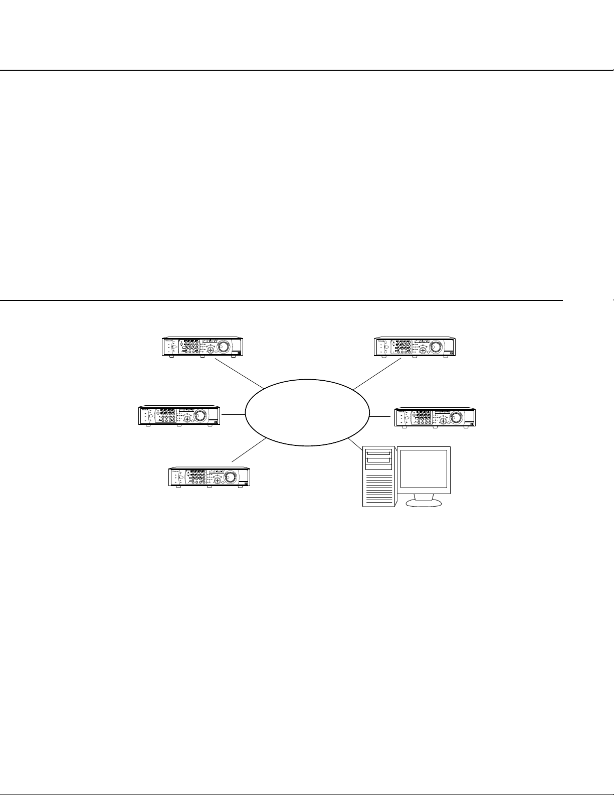
SYSTEM CONFIGURATION
The PC Software Package WV-AS60 (hereinafter referred to as WV-AS60) is designed for integrated management
of up to 100 Panasonic WJ-HD300 series digital disk recorders connected to a network such as a LAN or the
Internet, and runs on the Microsoft®Windows®operating system.
This software provides users with the following operations using a remote personal computer (PC):
• Display images from cameras connected to a recorder on a remote PC monitor
• Play the recorded images stored in a recorder on a PC monitor
• Download the recorded images stored in a recorder and save them onto the hard disk drive of a PC
• Search downloaded images by filtering (using search conditions such as time and date, etc.) and play the search
results
This software consists of the following 2 applications:
[Main application]: The main application runs in the following 2 modes.
<Network mode>
In this mode, it is possible to control a recorder remotely via a network. Run this application in this mode to
monitor live images from cameras connected to a recorder or play the recorded images stored in a recorder.
<Local mode>
In this mode, it is possible to access downloaded recorded images saved onto the hard disk drive of a PC.
Run this application in this mode to search and play downloaded recorded images.
[Downloader]: This application downloads recorded images from a recorder. This is the resident application (in the
system tray). Once the PC is turned on, the downloader runs in the background of the PC.
It is possible to start the main application from the downloader.
Even though the main application is closed, the downloader will keep running and perform the schedule function that
downloads recorded images automatically.
When the downloader is closed, the main application will close automatically.
Network
ALARM
TIMER
HDD 2
ERROR
HDD 1
ALARM
SUSPEND
ALARM
RESET
OPERATE
MONITOR1
MONITOR2
1
5
9
13
2
6
10/0
14
3
7
11
15
4
8
12
16
SEQSHIFT OSD
PAN/
TILT
STOP
PLAY PAUSE
REC
-
REC STOP
ZOOM/
FOCUS
TEXT
COPY
DISK SELECT
EL-ZOOM
MARK
LOGOUT
IRIS
PRESET
/AUTO
A-B
REPEAT
GOTO
LAST
LISTED
SEARCH
BUSY
SETUP
/ESC
SET
REV
– +
FWD
PULL
Digital Disk Recorder
WJ-HD
PAN/TILT
SLOW
ALARM
TIMER
HDD 2
ERROR
HDD 1
ALARM
SUSPEND
ALARM
RESET
OPERATE
MONITOR1
MONITOR2
1
5
9
13
2
6
10/0
14
3
7
11
15
4
8
12
16
SEQSHIFT OSD
PAN/
TILT
STOP
PLAY PAUSE
REC
-
REC STOP
ZOOM/
FOCUS
TEXT
COPY
DISK SELECT
EL-ZOOM
MARK
LOGOUT
IRIS
PRESET
/AUTO
A-B
REPEAT
GOTO
LAST
LISTED
SEARCH
BUSY
SETUP
/ESC
SET
REV
– +
FWD
PULL
Digital Disk Recorder
WJ-HD
PAN/TILT
SLOW
Page 5

5
FEATURES
Image download
It is possible to download recorded images stored in the recorder onto the hard disk drive on a PC using this function. Downloaded images can be played using the main application.
There are 2 ways to download recorded images: schedule download and manual download.
• Schedule download
Downloads images automatically according to the schedule set (start time and date of downloading, the recording time range of images to be downloaded) in advance.
• Manual download function
Downloads the recorded images manually by designating the recording time range while playing the recorded
images stored in the recorder.
Important:
When ON is selected for the host authentication on the recorder, it is impossible to monitor live or recorded
images by accessing the recorder using an unregistered PC as a host. However, schedule download is available
even if ON is selected for the host authentication. Manual download is available only when using a registered
host since it is necessary to set the time range of the recorded images to be downloaded during playback.
Remote control of the recorder
It is possible to simultaneously monitor live or recorded images of up to 16 channels of the recorder.
It is possible to display images on a single or a multi-screen (4-/9-/16-split screen) and assign camera channels to
any segment of a multi-screen.
By registering these settings (single or multi-screen, camera channel assignment), as a favorite, it is possible to call
them up directly.
The following operations are available with the cameras connected to the recorder are operable when its live or
recorded images are displayed.
• Camera control
It is possible to control cameras with functions such as panning, tilting, zooming, etc..
• Status display
It is possible to display status of the recorder (alarm, recording, error, etc.) on a monitor.
• Search and play
It is possible to play the recorded images by searching using recording event search, VMD search or marking
search.
• Recorder control
It is possible to control the recorder with functions such as starting/stopping manual recording, attaching text
information to recorded images, displaying a log of the recorder, copying recorded images, etc.
Page 6

6
Image file management
• Image file database
Downloaded images will be registered in the database. It is possible to search registered images by filtering
(recorder, time and date, recording event, etc.). It is possible to attach text information as a comment and the
attached comment can be a keyword for filtering. The icons (new /checked ) attached to images make it
easy to identify downloaded images at a glance.
• Image playback
There are 2 ways of playback: multiple channel playback and 4-file simultaneous playback.
When downloading the image of the designated multiple channels, playback of images recorded from multiple (4,
9 or 16) channels is available. It is possible to simultaneously play 4 files by dragging and dropping 4 files onto
the desired areas of the 4-split screen respectively.
It is also possible to print, save as a jpeg file, and save images on a CD-R or DVD-R by designating a certain
period of images.
Alarm management
An alarm log will be created by using the transmission from the recorder to an FTP server. When an alarm log is
updated, the newest information will be displayed on a monitor. It is possible to access directly a corresponding
alarm image from the displayed information to play it.
• Create an alarm log by using the transmission from the recorder to an FTP server
The recorder automatically transmits the recorded images to an FTP server at an event occurrence (FTP alarm
transmission function). By using this function, an alarm log will be updated by referring to information of the
recorded images transmitted to an FTP server directory on a PC. It is necessary to register an FTP server directory on the SETUP MENU of the recorder and the main application. Refer to page 136 for descriptions of how to
register an FTP server directory for the main application. Refer to the Operating Instructions of the recorder for
descriptions of how to register an FTP server directory for the recorder.
Notes:
• To use this function, it is required that IIS (Microsoft®Internet Information Services) is running on a PC on
which this software is installed.
• Transmitted recorded images from the recorder to an FTP server would have been recorded from the start
time of the event recording. When events occurred sequentially, only images recorded from the start time of
the first event recording will be transmitted.
Page 7

7
Enhanced security
It is possible to enhance security by using the user authentication function (requires entering a user name and password). In addition, only users who registered as the administrator can perform the settings of this software. Users
who are not registered as the administrator cannot perform the settings of this software. It is also possible to restrict
operable functions by applying the user type to each user. In combination with the user authentication of this software and the user level setting and the priority setting of the recorder, it is possible to have well-designed user management for remote operation.
Local PC maintenance
• Management of the available disk space of a PC
It is possible to check the available disk space of the hard disk drive used to store downloaded images.
Downloading will not be performed when the available disk space is running out and there is no space to save
images.
• Deletion of the older image files by designating the time and date
It is possible to delete image files on the hard disk drive of a PC that were recorded before a designated time and
date.
• Deletion of image files by setting the file retention period
It is possible to delete recorded image files automatically when the set number of days has passed from the day
the image was recorded.
System specifications
This software has the following system specifications:
• Up to 100 recorders can be registered
• Up to 32 users can be registered
• 5 user types are available
• Up to 400 schedules can be registered
• Up to 500 favorites can be registered
• Up to 10 concurrent accesses for downloading are available
• Displaying images from up to 16 cameras on a monitor is available
• Displaying playback images of up to 4 files is available
Note:
When 2 or more WV-AS60’s are used, up to 4 concurrent accesses (4 PCs) to a single recorder are available.
(A single recorder can accept up to 8 concurrent accesses by users, but the recorder counts a single access
using this software as 2 accesses.)
When exceeding the maximum number of concurrent access due to increase in the number of accesses using
web browser or FTP accesses, connection with the recorder may be disconnected and a black screen may be
displayed.
Page 8

8
ABOUT THESE OPERATING INSTRUCTIONS
SYSTEM REQUIREMENT
These operating instructions provide the instructions on the assumption that Windows®XP Professional Edition is
installed on the PC to be used. The illustrations or graphics in these operating instructions may differ depending on
the settings of the operating system, or when another operating system is installed on the PC to be used.
These operating instructions can be divided roughly into 4 chapters as follows:
• Preparations (pages 12 - 24)
Contains descriptions of the required preparations to operate this software including descriptions of how to install
this software.
• Operations (pages 25 - 133)
Contains descriptions of how to operate the applications.
• Setup (pages 134 - 157)
Contains descriptions of how to perform the settings of the recorder, the user registration, the schedule recording
and the optional settings of the applications. Before running the applications, perform the required settings.
• References (pages 158 - 164)
Contains descriptions of how to solve problems, about the messages displayed on a monitor, etc.
It is recommended to install this software on a PC that meets the following system requirements.
OS Microsoft
®
Windows®2000 Professional SP4
Microsoft®Windows®XP Professional or Home Edition SP1
Computer IBM PC/AT Compatible
CPU Pentium®4 1.4GHz or faster
Memory 512 MB or more
Hard disk drive 80 MB of available disk space for installation*
Monitor 1024 x 768 pixels or more, 16-bit HIGH color or better
Network Interface 10/100Mbps Network interface card must be installed
Web Browser Microsoft®Internet Explorer 5.5SP2, 6.0 SP1
Other web browsers are not compatible with this unit.
*: It is necessary to prepare other disk space exclusively as storage for files downloaded from the recorder in addi-
tion to the required available disk space for installation.
Notes:
• If a sound card is not installed on a PC in use, it is impossible to hear audio playback.
• This software must be installed or started by the administrator. Otherwise, any problems will not be covered by
the warranty.
Page 9

9
TRADEMARKS AND REGISTERED TRADEMARKS
LIMITATION OF LIABILITY
• Adobe®, Adobe logos, and Acrobat®are registered trademarks of Adobe Systems Incorporated in the U.S.
and/or other countries.
• Microsoft®, Windows®and Windows®XP are registered trademarks of Microsoft Corporation in the U.S. and/or
other countries.
• Intel®and Pentium®are trademarks of Intel Corporation.
• Other names of companies and products contained in these operating instructions may be trademarks or regis-
tered trademarks of their respective owners.
IN NO EVENT SHALL MATSUSHITA ELECTRIC INDUSTRIAL CO., LTD. BE LIABLE TO ANY PARTY OR ANY
PERSON, EXCEPT FOR REPLACEMENT OR REASONABLE MAINTENANCE OF THE PRODUCT, FOR THE
CASES, INCLUDING BUT NOT LIMITED TO BELOW:
(1) ANY DAMAGE AND LOSS, INCLUDING WITHOUT LIMITATION, DIRECT OR INDIRECT, SPECIAL, CONSE-
QUENTIAL OR EXEMPLARY, ARISING OUT OF OR RELATING TO THE PRODUCT;
(2) PERSONAL INJURY OR ANY DAMAGE CAUSED BY INAPPROPRIATE USE OR NEGLIGENT OPERATION
OF THE USER;
(3) UNAUTHORIZED DISASSEMBLE, REPAIR OR MODIFICATION OF THE PRODUCT BY THE USER;
(4) ANY PROBLEM, CONSEQUENTIAL INCONVENIENCE, OR LOSS OR DAMAGE, ARISING OUT OF THE SYS-
TEM COMBINED BY THE DEVICES OF THIRD PARTY.
Distributing, copying, disassembling, reverse compiling, reverse engineering, and also exporting in violation of export
laws of the software provided with this product, is expressly prohibited.
STANDARD ACCESSORIES
CD-ROM ................................................................... 1 pc.
Label (with product key) ........................................... 1 pc.
Installation Guide ...................................................... 1 pc.
Page 10

10
TERMS USED IN THESE OPERATING INSTRUCTIONS
These are descriptions of the basic terms used in these operating instructions.
Terms
Recorder
Camera
Image file
Download
Schedule
Main application
Downloader
User
Event log
Event action
Recording event
Recording event list
Descriptions
Panasonic WJ-HD 300 series digital disk recorder.
Indicates the camera connected to the recorder.
Indicates the downloaded images recorded on the recorder. It is possible to play
them using this software.
• An image file will contain images from multiple camera channels depending on
the channel selection for the schedule settings. Refer to page xx for further
information.
• An image file will contain images from only a single camera channel when an
image file is manually downloaded.
Transferring image files from the recorder to a PC. Schedule download (download
according to the schedule settings) and manual download (download manually
while monitoring playback images) are available.
The set schedules to download image files from the recorder automatically. The
downloader will start downloading automatically by designating a download start
time and a recorded time range of image files to be downloaded.
Main application works in the network mode (operates the recorder via a network)
and in the local mode (plays image files downloaded from the recorder). The basic
operation of this software can be performed using this application.
Use this resident application on a PC to download image files stored in the
recorder. This application downloads image files according to the schedule setting.
Use this software also to download image files manually.
Operator of this software. A single user can be registered as the administrator. The
administrator can perform/manage the settings of this software.
Indicates the logs of the recording events detected by the recorder.
Indicates the actions that the recorder performs at an event occurrence. Refer to
the Operating Instructions of the recorder for further information.
Indicates the following events or operations that become the trigger for recording:
VMD (video motion detection), TERMINAL, COMMAND, VIDEO LOSS, EMERGENCY, MANUAL, SCHEDULE.
Indicates a list of recording events searched from the recorded images stored in
the recorder. The recording event list contains the recording start time, the recording channel and the recording event type.
Page 11

Terms
11
Connection with FTP server
Alarm log
Live image
Alarm image
Descriptions
It is possible to update an alarm log by referring to information of the recorded
images transmitted to an FTP server directory on a PC. To do this, it is required
that IIS (Microsoft
®
Internet Information Services) is running on the PC on which
this software is installed.
It is possible to run the FTP server of IIS on a PC whose OS is Windows®XP
Professional Edition or Windows®2000 Professional. However, it is necessary to
install IIS additionally. To install IIS, do the following:
1. Select "Add/Remove Windows Components" from "Add or Remove Programs "
([Control Panel] - [Add or Remove Programs]).
2. Add "Internet Information Services (IIS)" using the "Windows Components
Wizard".
3. After adding "Internet Information Services (IIS)", right click the icon of "My computer" and select "Manage" from the pop-up menu. The "Manage" window will be
displayed.
4. Perform the settings of the FTP server on the displayed window by selecting
"Internet Information Services (IIS)" from "Services and Applications".
Refer to the operating instructions on the Windows operating system or "Help".
When using the Windows® XP Home Edition, install other FTP server software to
use this function.
Log created by using the transmission from the recorder to an FTP server directory
on a PC. It is possible to access directly a corresponding image from this log.
Indicates live images from cameras connected to the recorder.
Indicate images recorded at an event occurrence.
Page 12

12
INSTALLATION
Installing this software
Install this software as follows.
1. Insert the provided CD-ROM into the PC disk drive.
Entering the product key (enter the 20 alphanumeric characters) will be required during the installation. Enter the
product key written on the provided label.
When the "standard" installation has been performed, the folder "Panasonic" will appear in "C: \Program Files".
The executable file "as60.exe" will be copied in the folder " WV-AS60".
2. Double click "Setup.exe".
3. Follow the installation wizard. When installation is complete, the application will be added to "Programs"
in "Start".
Uninstalling this software (In case of using Windows XP)
If required, uninstall this software as follows. The files downloaded from the recorder will not be deleted.
1. Open "Add/Remove Programs" in "Control Panel".
2. Select the application to be uninstalled. The uninstall program will be launched and the wizard will be
displayed.
3. Follow the uninstall wizard. When uninstall is completed, the application will be uninstalled from the PC.
Page 13
13
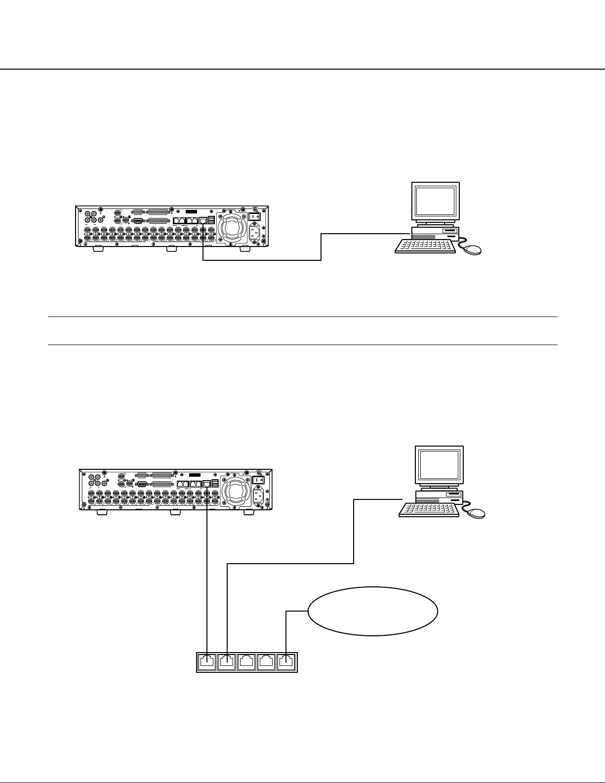
CONNECTING WITH THE RECORDER
When connecting the recorder to a PC, the required hardware and cables are different depending on the system
configuration. Prepare before connecting.
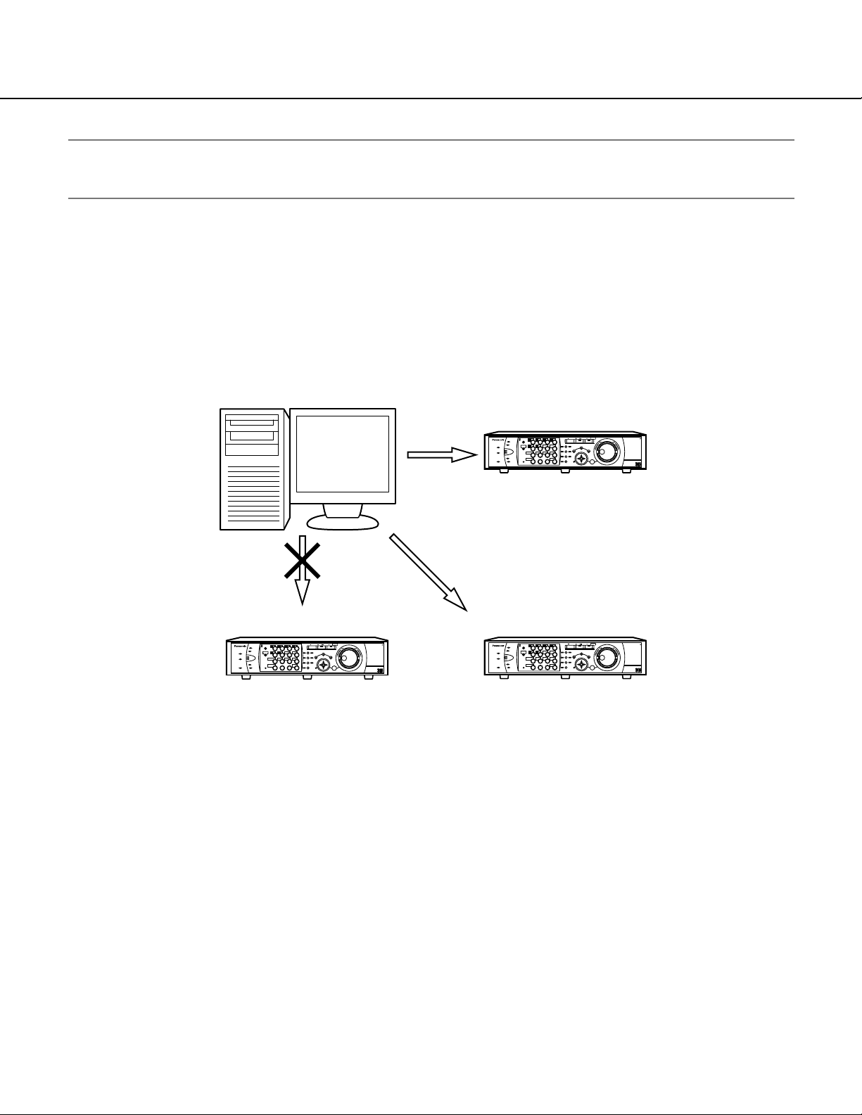
Connecting the recorder and a PC directly
Connecting the recorder to a PC directly using a LAN cable.
Important:
Use a cross cable when connecting the recorder and a PC directly without using a hub or a router.
Add the recorder to an existing network
Connecting the recorder to a PC via a hub or a router. Connecting the recorder to a hub using a LAN cable.
1
1
1515141413
SERIAL ALARM
CASCADE
OUT
2
MONITOR OUT CASCADE IN
MONITOR (VGA) ALARM/CONTOROL
13
12121111101099887766554433221
VIDEO
IN
OUT
3
4 2
AUDIO IN AUDIO OUT
16
16
IP Address: 192.168.0.250
Subnet mask: 255.255.255.0
MODE
COPY 1
12
DATA
EXT STORAGE10/100BASE-TRS485(CAMERA)
1
LAN cable
(Not provided: 10BASE-T/100BASE-Tx
Category 5, Cross)
SIGNAL GND
POWER
AC IN
IBM PC/AT Compatible
IP Address: 192.168.0.x (except 0, 250 and 255)
Subnet mask: 255.255.255.0
Recorder
SERIAL ALARM
VIDEO
Recorder
DATA
MODE
COPY 1
12
EXT STORAGE10/100BASE-TRS485(CAMERA)
1
SIGNAL GND
POWER
AC IN
IN
OUT
3
1
4 2
AUDIO IN AUDIO OUT
16
16
1515141413
1
CASCADE
OUT
2
MONITOR OUT CASCADE IN
MONITOR (VGA) ALARM/CONTOROL
13
12121111101099887766554433221
IP Address: 192.168.0.250
Subnet Mask: 255.255.255.0
Gateway Address: 192.168.0.1
LAN cable
(Not provided: 10BASE-T/100BASE-Tx
Category 5, Straight)
Hub/Router
IP Address: 192.168.0.1
Subnet Mask: 255.255.255.0
IBM PC/AT Compatible
IP Address: 192.168.0.x (except 0, 1, 250 and 255)
Subnet Mask: 255.255.255.0
Gateway Address: 192.168.0.1
LAN (Local Area Network)
Page 14
14
Performing the network settings
In case of the following network environment, it is not necessary to perform network settings.
IP Address: 192.168.0.2 - 192.168.0.249, 192.168.0.251 - 192.168.0.254
Subnet Mask: 255.255.255.0
Gateway Address: 192.168.0.1
When the network settings are different from the settings above, perform the network settings of the recorder and
the PC.
Performing network settings of the recorder
Perform the settings on the SETUP MENU of the recorder to conform to the network environment of the PC.
Refer to the operating instructions of the recorder for further information about network settings ([SETUP] - [Comm]
Settings for communication with other devices – [NW Setup 2] Network connection settings).
Performing the network settings of a PC
Change the TCP/IP setting of the PC to conform to the setting of the recorder.
It is necessary to set the IP address of the PC to "192.168.0.XX (a number from 2 to 254 except 250)" to access the
recorder.
In these operating instructions, settings are performed on Windows XP as examples. Refer to the operating instructions of the respective OS for further information. Start the following operations just after the PC is started up.
Important:
Log in to the PC as an administrator.
Step 1
On the taskbar, click "Start", and then click the "Control
Panel".
Page 15
15
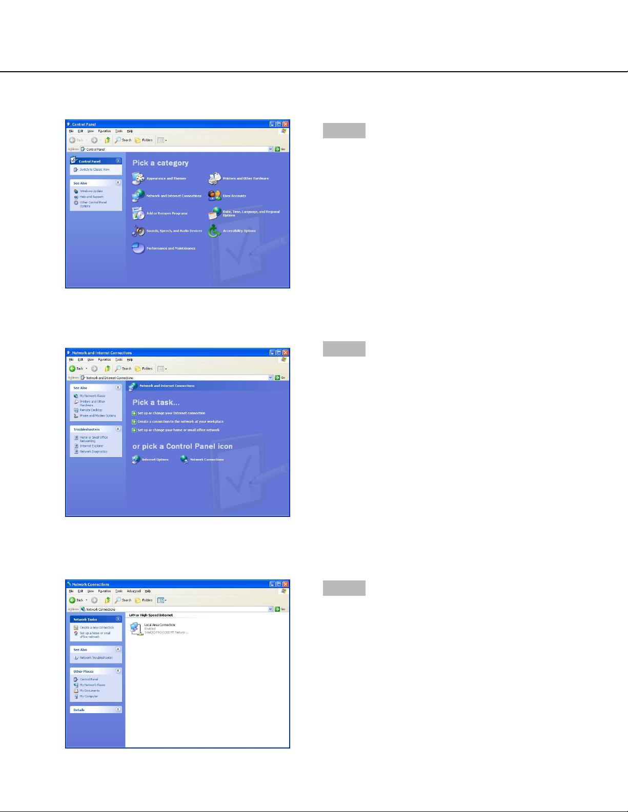
The control panel will be displayed.
Step 2
Click the "Network and Internet Connections" icon.
The "Network and Internet Connections" window will be
displayed.
Step 3
Click "Network Connections".
The "Network Connections" window will be displayed.
Step 4
Double click "Local Area Connection".
Page 16
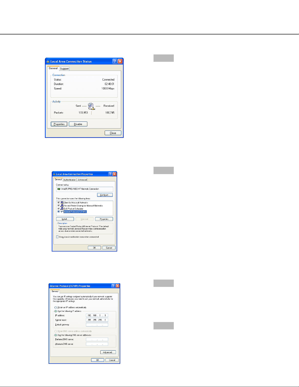
16
The "Local Area Connection Status" window will be displayed.
Step 5
Click "Properties".
The "Properties" window of "Local Area Connection" will
be displayed.
Step 6
Click "Internet Protocol (TCP/IP)", and then click
"Properties".
The "Properties" window of "Internet Protocol (TCP/IP)"
will be displayed.
Step 7
Click "Use the following IP address" and enter the IP
address and the subnet mask as follows;
• IP Address: 192.168.0.9
• Subnet Mask: 255.255.255.0
Step 8
Click the "OK" button and close the window.
Page 17

17
Registration of the recorder
It is necessary to register the recorder to play or download recorded images from the recorder. Refer to page xx for
descriptions of how to register the recorder.
Note:
It is necessary to perform the connection test to complete the recorder registration. The connection test checks
whether the recorder is connected and located in the registered IP address or the host name.
Page 18
18
MAIN APPLICATION
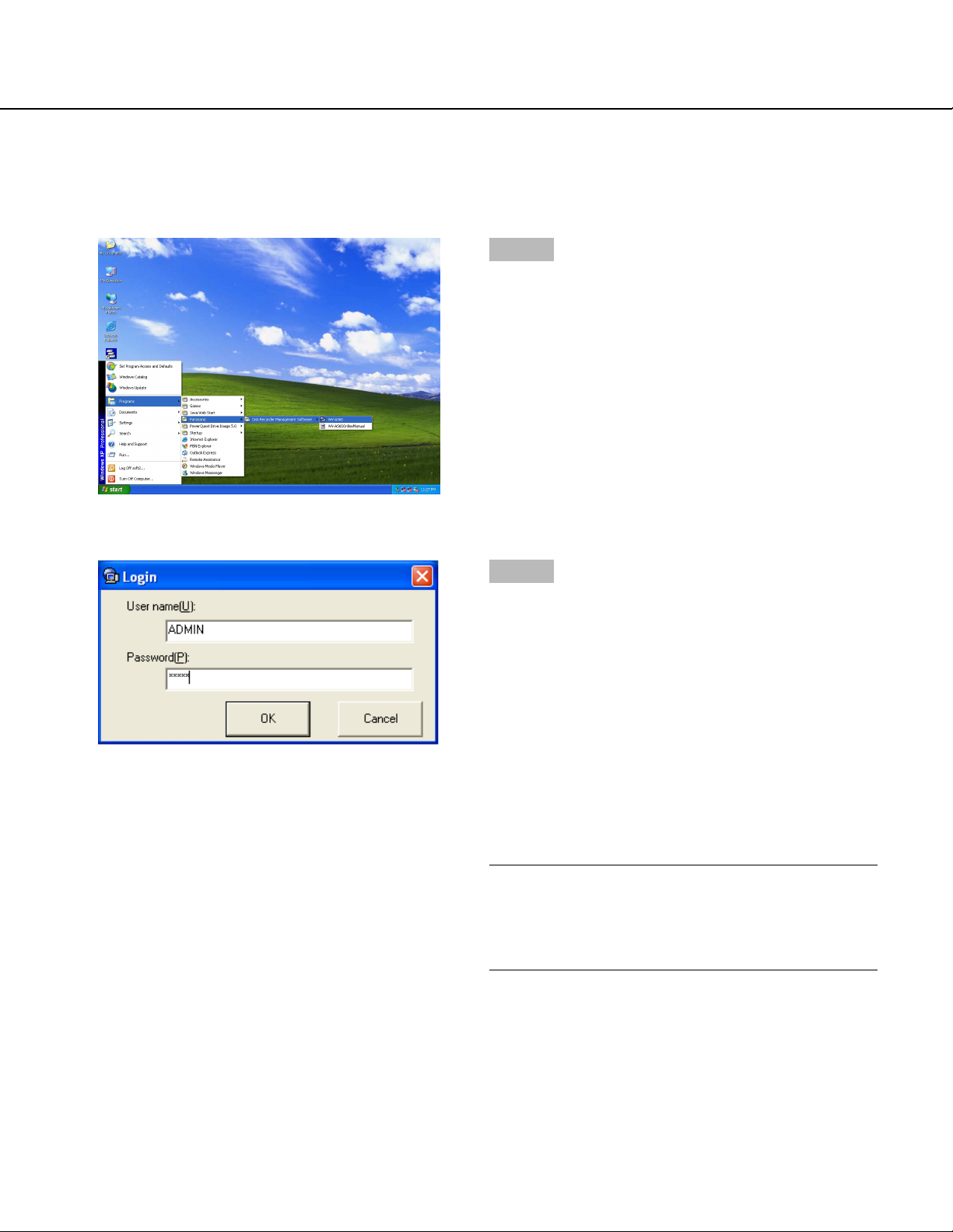
Start the main application (open the operation window)
Display the operation window as below.
Step 2
Enter a user name and password.
When this software is installed, only the administrator
(ADMIN) is registered. When logging in the main application just after the installation, enter "ADMIN" for the
user name and "12345" for the password.
It is possible to set the auto login function. A user registered as an auto login user can log in without entering a
user name and password when the auto login function
is on. (The default setting of the user authentication is
ON. (The auto login function is disabled.) Changing the
settings of the user authentication is available on the
option window.
Note:
When OFF is selected for the user authentication on
the option window, the login window will not be displayed. Refer to page 157 for descriptions of how to
perform the settings.
Step 1
Select "WV-AS60" from the "Start" menu ("Start" - "All
Programs" - "Panasonic" - "Recorder management software" - "WV-AS60").
The login window will be displayed after the startup
splash image is displayed.
Page 19
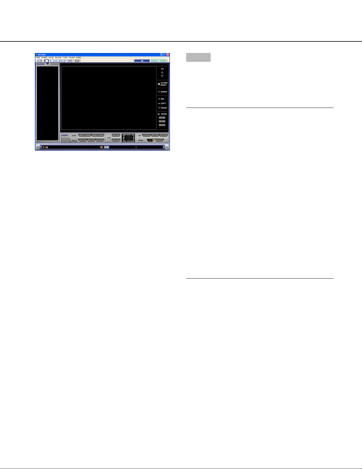
19
Step 3
Click the [OK] button.
The operation window (in the network mode) will be displayed.
When the operation window is not displayed, refer to the
next page.
Notes:
• When a combination of camera channels and a
multi-screen are registered as a favorite, the registered favorite will be displayed in the image display
area of the operation window. (Registered camera
channels will be displayed in the registered multiscreen.)
• When "Local mode" is selected for "Default screen"
of the optional settings (on the option window), the
local mode list window will be displayed.
• When the message window is displayed after clicking the [OK] button, refer to "DISPLAYED MESSAGE AND SOLUTIONS" on page 162 and follow
the descriptions.
• To enhance the security, change the password for
the administrator before start operating the main
application. It is recommended to change the password for the administrator periodically.
• When the message window is displayed by clicking
the [OK] button, refer to the "DISPLAYED MESSAGE AND SOLUTIONS" on page 162 and follow
the descriptions.
Page 20
20
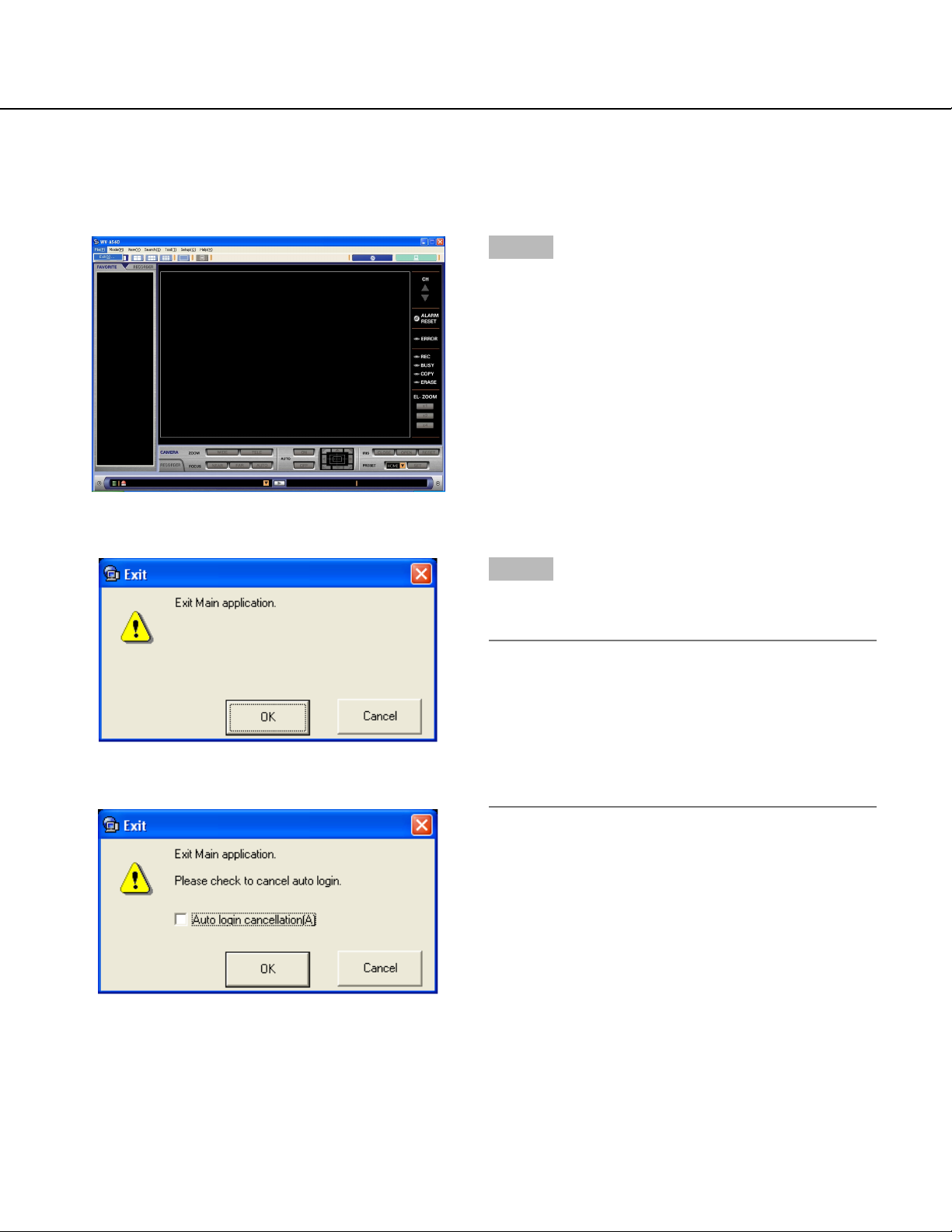
Exit the main application (close the operation window)
Close the operation window as follows.
Step 1
Select "Exit (X)" from the menu bar ("File (F)" - "Exit
(X)") or close the operation window by clicking the [×]
button at the top right of the window.
The "Exit" window will be displayed.
Step 2
Click the [OK] button on the "Exit" window.
The operation window will be closed.
Note:
When the auto login function is on, it is possible to
cancel the auto login function on the "Exit" window.
When canceling the auto login function, check the
checkbox of " Auto login cancellation (A)" on the
"Exit" window and click the [OK] button. The login
window will be displayed when logging in the next
time.
Page 21

21
THE NETWORK MODE AND THE LOCAL MODE
The main application works in the network mode or the local mode.
Network mode
• It is possible to display live images from the cameras connected to the recorder or play the recorded images
stored in the recorder.
Images of up to 16 channels can be simultaneously displayed (on a 16-split screen).
• It is possible to switch to display images of 1/4/9/16 channels on a single/4-/9-/16-split screen respectively.
• It is possible to select the camera channels of a single recorder or multiple recorders.
• It is possible to operate the recorder using functions such as starting/stopping manual recording, copying, etc..
• It is possible to register a "favorite (combinations of the camera channels and the areas of the multi-screen)" and
set it as the default screen.
• It is possible to search for recorded images stored in the recorder by recording event, marked point or the time
and date when a motion is detected. It is possible to simultaneously search two or more recorders using the
same conditions.
• It is possible to download a specific duration of recorded images while playing them by designating the start time
and the end time.
Local mode
• It is possible to play the recorded images downloaded from the recorder. Even though two or more channels are
selected for downloading, the recorded images of the selected channels will be saved as a single file.
• There are 2 methods to play the downloaded file: play a single file or play 4 files.
When playing a single file, it is possible to play the recorded images from multiple camera channels (selected in
advance) on a 4-/9-/16-split screens. When playing 4 files, only a single camera channel for each file can be
played.
• It is possible to save a specific duration of a downloaded image as a file. It is possible to play the saved file using
the exclusive viewer software even on a PC on which the WV-AS60 is not installed. It is also possible to save the
recorded image as a still picture (JPEG).
Click this button to switch to the network mode.
Click this button to switch to the local mode.
How to switch the mode
Click the network button or the local mode button on the
menu bar on the operation window to switch the mode.
Page 22

22
USER MANAGEMENT
Exclusive settings menus for the administrator
This software manages the administrator and the registered users. Only the administrator can perform the settings of
this software. When a registered user logs into this software, the menus for the settings of this software will not be
displayed.
Only when the administrator logs in, will the menus for the settings be displayed.
The following operations are only for the administrator:
• Browsing the system log (page 118)
• Deletion of the downloaded images (pages 114 and 116)
• Registration of recorders, editing or deletion of the registered recorder information (pages 134, 142 and 143)
• Registration of users, editing or deletion of the registered user information (pages 144, 145 and 146)
• Creating schedules, editing or deletion of the registered schedules (pages 150, 153 and 154)
• Optional settings (page 155)
Administrator
• A single administrator is registered at the default setting.
The administrator can perform all the settings and operate all the functions of this software. Only a single administrator can manage this software. It is impossible to delete or add the administrator.
The default user name and password of the administrator is as follows:
User name: ADMIN
Password: 12345
• To enhance the security, change the password for the administrator before start running this software. It is recommended to change the password for the administrator periodically. Refer to page 149 for descriptions of how
to change the password.
• When the administrator of this software operates the recorder via a network after logging in this software, the
administrator can operate the recorder as the administrator of the recorder.
User registration
• Up to 32 users can be registered
• No user is registered at the default settings (Register users according to your needs. (page 144))
• It is possible to enable/disable operable functions to restrict users by applying the user type to them. (Set the
user type according to your needs. (page 148))
Important:
It is necessary to enter the user name and the password registered in this software when operating the recorder
via a network. (The user name and the password will be required to log into the recorder)
Therefore, the users registered in this software should also be registered in the recorder with the same user
name and the password.
When the user name or the password for this software is changed, it is also necessary to change it for the
recorder, and vice versa.
Otherwise, it is impossible to operate the recorder.
Page 23
23
Note:
It is possible to perform the detailed user settings to restrict users via the user settings of this software and of the
recorder, such as setting operable cameras for users independently.
<Example>
It is possible to perform the settings for a specific user as follows:
Recorder A: When registering the user, set all cameras as operable for this user.
Recorder B: When registering the user, set camera 1, 2 and 3 as operable for this user.
Recorder C: Do not register any users.
PC: User1
Recorder A
STOP
PLAY PAUSE
REC
-
MONITOR1
MONITOR2
TIMER
1
2
3
ERROR
ALARM
ALARM
SUSPEND
OPERATE
SEQSHIFT OSD
5
6
7
ALARM
RESET
TEXT
COPY
DISK SELECT
9
10/0
11
HDD 1
EL-ZOOM
HDD 2
13
14
15
REC STOP
4
GOTO
PAN/
LAST
TILT
SEARCH
SETUP
PAN/TILT
/ESC
SLOW
8
ZOOM/
A-B
FOCUS
REPEAT
MARK
IRIS
LISTED
12
PRESET
LOGOUT
/AUTO
SET
16
BUSY
All cameras are operable
REV
– +
PULL
FWD
Digital Disk Recorder
WJ-HD
STOP
PLAY PAUSE
REC
-
MONITOR1
MONITOR2
TIMER
1
2
3
ERROR
ALARM
ALARM
SUSPEND
OPERATE
SEQSHIFT OSD
5
6
7
ALARM
RESET
TEXT
COPY
DISK SELECT
9
10/0
11
HDD 1
EL-ZOOM
HDD 2
13
14
15
REC STOP
REV
4
PAN/
TILT
8
ZOOM/
FOCUS
MARK
IRIS
12
PRESET
LOGOUT
/AUTO
16
FWD
GOTO
LAST
SEARCH
SETUP
PAN/TILT
/ESC
SLOW
A-B
REPEAT
– +
LISTED
BUSY
Digital Disk Recorder
SET
WJ-HD
Cannot log into the recorder
Recorder BRecorder C
STOP
PLAY PAUSE
REC
-
PULL
MONITOR1
MONITOR2
TIMER
1
2
3
ERROR
ALARM
ALARM
SUSPEND
OPERATE
SEQSHIFT OSD
5
6
7
ALARM
RESET
TEXT
COPY
DISK SELECT
9
10/0
11
HDD 1
EL-ZOOM
HDD 2
13
14
15
REC STOP
4
PAN/
GOTO
TILT
LAST
SEARCH
SETUP
PAN/TILT
/ESC
SLOW
8
ZOOM/
A-B
FOCUS
REPEAT
MARK
IRIS
LISTED
12
PRESET
LOGOUT
/AUTO
SET
16
BUSY
REV
– +
PULL
FWD
Digital Disk Recorder
WJ-HD
Only camera1, 2 and 3
are operable
Page 24
24
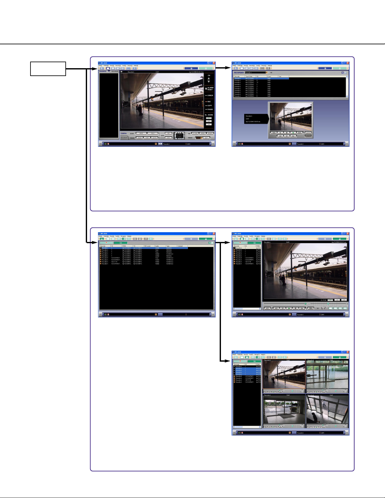
PRINCIPAL WINDOW CHART
Login
Operation window (page 25)
When "Network (N)" is selected for
"Default screen" of the optional settings
(on the option window), this window will
be displayed after logging in.
Network mode
Local mode
List display window (page 80)
When "Local (L)" is selected for "Default
screen" of the optional settings (on the
option window), this window will be displayed after logging in.
Playback window (displaying images
of a single file in the playback image
display area) (page 85)
Playback window (displaying images
of 4 files in the playback image display
area) (page 89)
Search result list window (page 36)
Page 25
25
THE OPERATION WINDOW IN THE NETWORK MODE
Operation window
q Title bar
The title of the main application will be displayed.
w Menu bar
The menu items will be displayed.
e Tool bar (Page 27)
The icons will be displayed.
r FAVORITE tab (Page 27)
A list of combinations of camera channels and multiscreen types registered as favorites will be displayed. It is possible to display images of a desired
favorite or change names of favorites on this tab.
t RECORDER tab (Page 28)
Recorders and cameras operable from this application via a network will be displayed. It is possible to
display live images by selecting a recorder or
change registered information of recorders on this
tab.
y Image display area (Page 29)
Images from the recorder will be displayed in this
area. It is possible to split this area into 4, 9 or 16 to
display images from multiple cameras.
u Information display area (Page 28)
Information of displayed images such as playback
speed, recorder title, camera title, the time and date,
the start point and the end point will be displayed in
this area.
i Channel switch buttons
button: Click this button to display images of the
previous channel.
button: Click this button to display images of the
next channel.
o Recorder status display area (Pages 30 and 31)
The indicators in this area will show the status of the
recorder (source of images currently displayed).
!0 Electronic zoom operation area
It is possible to perform the electronic zoom operation in this area.
[1x] button: Displays images in the original size.
[2x] button: Displays images in double size.
[4x] button: Displays images in quadruple size.
Note:
The electronic zoom operation area will be displayed
only when displaying images on a single screen.
u
q
w
e
r
t
y
i
o
!0
Page 26

26
!1 Camera control panel (Page 32)
Perform the camera operations such as zooming,
focusing, auto functions, etc. on this panel.
!2 Recorder control panel (Page 33)
Play the recorded images or control the recorder on
this panel.
!3 Status bar (Page 35)
The latest alarm status of the recorder or information
of a disk designated as storage for downloaded
images such as available disk space. The name of
the recorder currently selected or the camera also
will be displayed on this bar.
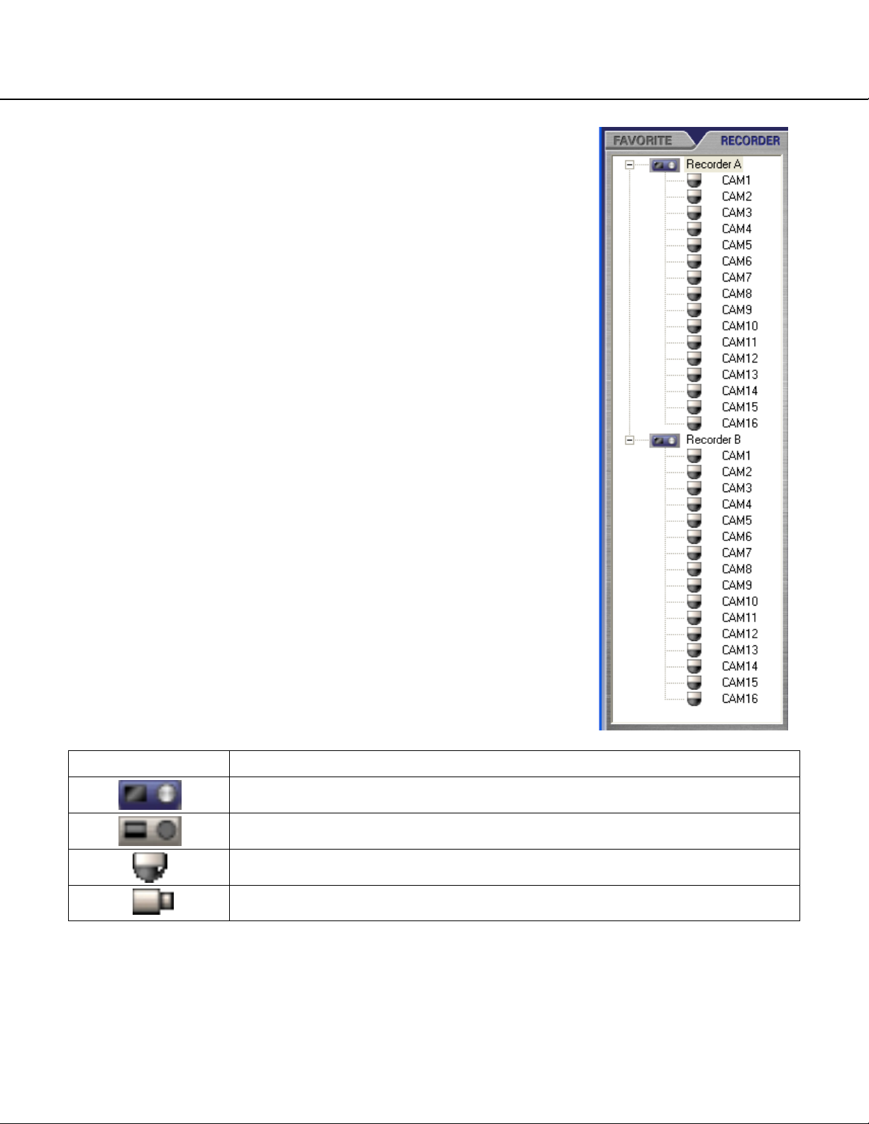
Page 27
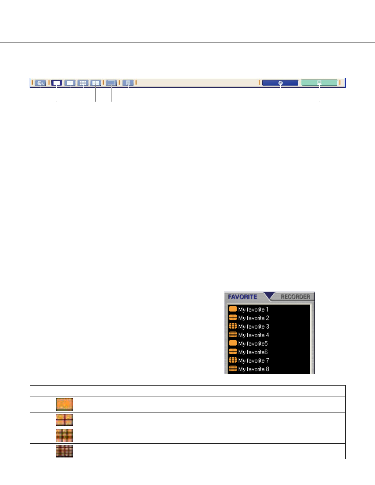
27
Tool bar
FAVORITE tab
A list of the registered favorites (combinations of the
camera channels and the areas of the multi-screen) will
be displayed in list form when this tab is clicked. An icon
displayed next to a name of a favorite indicates respective registered screen.
q [Search] button
Click this button to start searching the recorded
images on the recorder. The search window will be
displayed by clicking this button.
w [Single screen] button
Click this button to display images on a single
screen in the image display area.
e [4-split screen] button
Click this button to split the image display area into 4
sections. The image display area will become a 4split screen.
r [9-split screen] button
Click this button to split the image display area into 9
sections. The image display area will become a 9split screen.
t [16-split screen] button
Click this button to split the image display area into
16 sections. The image display area will become a
16-split screen.
y [Full screen] button
Click this button to display images on a full screen.
u [Recorder log] button
Click this button to check the logs of the recorder.
i [Network mode] button
Click this button to run this application in the network
mode. In the default setting, the application runs in
this mode.
o [Local mode] button
Click this button to run this application in the local
mode.
Icons
Descriptions
Registered to display on a single screen
Registered to display on a 4-split screen
Registered to display on a 9-split screen
Registered to display on a 16-split screen
w e r t y u i oq
Page 28
28
RECORDER tab
Registered recorders and cameras will be displayed when this tab is clicked.
Icons Descriptions
Registered recorder
Unregistered recorder
Camera capable of panning/tilting
Camera incapable of panning/tilting
Page 29
29
Information display area
q Status icons
Indicates that the status of the image currently displayed or the connection with the recorder.
w Playback speed
Displays the playback speed (STEP 1 - STEP 7) during playback.
e Recorder title
Displays the name of the recorder.
r Camera title
Displays the name of the camera.
t Time and date display
When displaying live images, the time and date of the clock of the recorder will be displayed.
When displaying recorded images, the time and date when the image was recorded will be displayed.
Note:
When displaying images on a 9-/16-split screen, only the status icon will be displayed.
Icons
No icon
Descriptions
Indicates that live images are being displayed
Indicates that recorded images are being displayed
Indicates that the connection with the recorder has failed
Indicates that no images are being displayed (black screen)
q w r t
Page 30
30
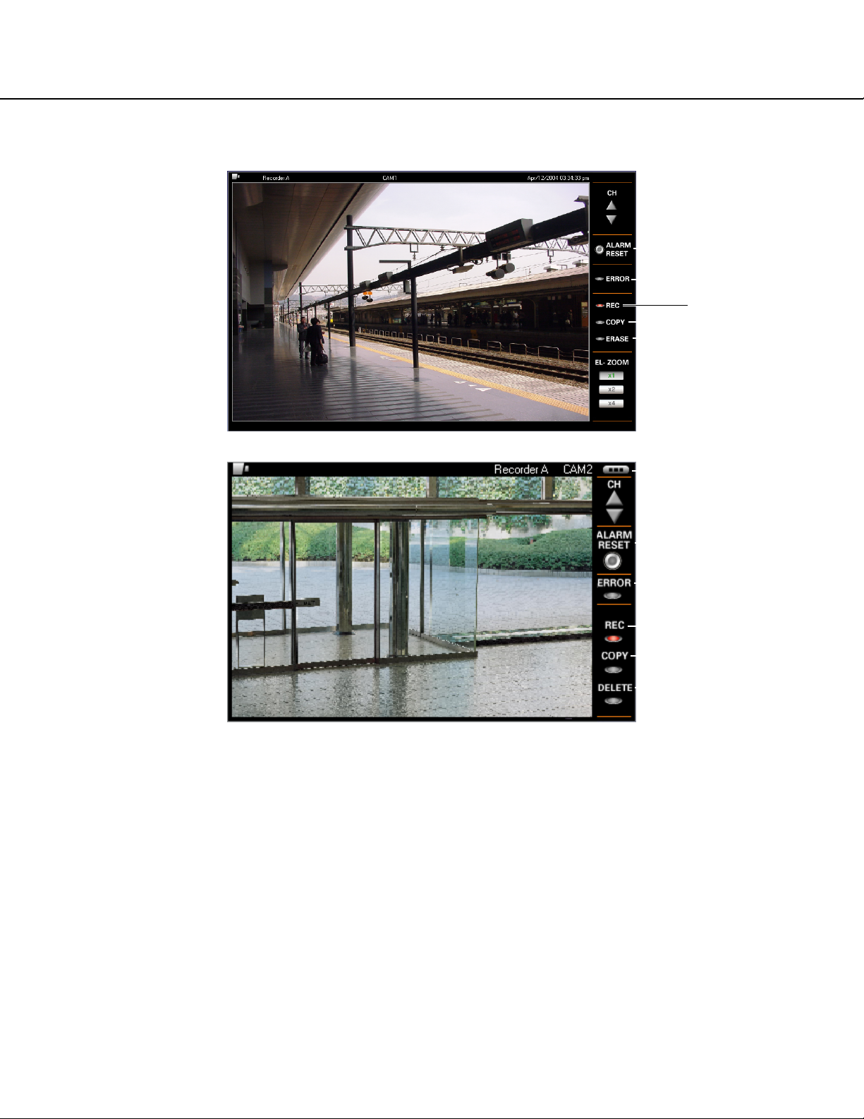
Recorder status display area (Single/4-split screen)
q [ALARM RESET] button
Lights when an alarm occurred. It is possible to reset the alarm status display by clicking this button.
w [ERROR] indicator
Lights when an error occurred.
e [REC] indicator
Lights when recording images.
r [COPY] indicator
Lights when copying recorded images.
t [DELETE] indicator
Lights when deleting recorded images.
y [Information display shift] button (only when displaying a 4-split screen)
Click this button to change information to be displayed on the information display area.
q
e
r
t
w
y
q
e
r
t
w
<4-split screen>
<Single screen>
Page 31

31
Recorder status display area (9-/16-split screen)
q [ALARM] indicator
Lights when an alarm occurred. It is impossible to reset the alarm status display when displaying images on a 9/16-split screen. Display images on a single/4-split screen to reset the alarm status display.
w [REC] indicator
Lights when recording images.
q
w
Page 32

32
Camera control panel
q [ZOOM] box
Zooming can be adjusted by clicking the [WIDE] button or the [TELE] button.
w [FOCUS] box
Focusing can be adjusted by clicking the [NEAR] button or the [FAR] button.
The auto focus function can be performed by clicking the [AUTO] button.
e [AUTO] box
The auto function of the camera will start by clicking the [ON] button. The auto function can be stopped by clicking the [OFF] button.
r Control pad
Clicking the buttons around the control pad can move (pan/tilt) a camera in the clicked direction.
Clicking inside the control pad can also adjust the vertical/horizontal position (pan/tilt) of the displayed image.
Panning/tilting speed will be faster if a clicked point gets farther from the center point of the control pad.
t [IRIS] box
Iris can be adjusted by clicking the [CLOSE] button or the [OPEN] button.
y [PRESET] box
Moves a camera to the preset position registered in advance. Click the [SET] button after selecting a preset number by clicking the button.
Registering preset positions is required to perform the preset function.
qte
wy
r
Page 33

33
Recorder control panel
Normally displayed
Displayed when the [REC] box (cover panel) is clicked
q [REW] button
Fast reverse playback will be performed. Playback
speed for the fast reverse playback will be changed
in the following order each time this button is clicked:
STEP2 (approx. 4x) - STEP3 (approx. 8x) - STEP4
(approx. 16x) - STEP5 (approx. 32x) - STEP6
(approx. 48x) - STEP7 (approx. 96x)
w [PREV RECORD] button
Skips to the previous recorded image and plays it.
e [REV PLAY] button
Reverse playback of a recorded image will be performed. When fast reverse playback is being performed, click this button to perform reverse playback
at normal playback speed.
r [PLAY] button
Playback of a recorded image will be performed.
When reverse playback is being performed, click this
button to perform playback at normal playback
speed.
t [NEXT RECORD] button
Skips to the next recorded image and plays it. When
there is no recorded image to skip to, the current
playback will continue.
y [FF] button
Fast playback will be performed. Playback speed for
the fast playback will be changed in the following
order each time this button is clicked:
STEP2 (approx. 4x) - STEP3 (approx. 8x) - STEP4
(approx. 16x) - STEP5 (approx. 32x) - STEP6
(approx. 48x) - STEP7 (approx. 96x)
u [PREV IMAGE] button
The previous frame will be displayed when this button is clicked during pausing.
i [PAUSE] button
The playback will be stopped when this button is
clicked during playback. The playback will be
resumed when this button is clicked during pausing.
o [STOP] button
Stops playback and displays a live image.
!0 [NEXT IMAGE] button
The next frame will be displayed when this button is
clicked during pausing.
q
w e r t y !1 !3 !6 !7 !8
u i o !0 !2 !9 @0 @1
!3
!5!4
Page 34

34
!1 [GO TO DATE] button
Displays the time and search window by clicking this
button.
!2 [GO TO LAST] button
Displays the latest recorded image by clicking this
button.
!3 [REC] box
Displays the [REC] button and the [REC STOP] button by clicking the [REC] box when the [REC] box
(cover panel) is closed. To close the [REC] box
(cover panel), click the [REC] box (cover panel)
again.
!4 [REC] button
Starts manual recording.
!5 [REC STOP] button
Stops manual recording.
!6 [Start] button
Sets the start time of the time range of a desired
recorded image to be downloaded by clicking this
button. The start time will be displayed in the information display area.
!7 [End] button
Sets the end time of the time range of a desired
recorded image to be downloaded by clicking this
button. The end time will be displayed in the information display area.
!8 [Download] button
Click this button to display the image download window.
!9 [TEXT] button
Click this button to display the attached text information. It is possible to display the text information
attached to the images currently playing by pausing
playback and clicking this button.
@0 [MARK] button
Mark by clicking this button during playback. When
marked, playback after searching for the marked
point is available. Playback will start from the
marked point. Up to 100 marked points can be registered. When more than 100 marked points are registered, the older marked points will be overwritten by
the newer ones. In this case, the oldest marked
point is the first to be overwritten. During playback in
a multi-screen, the point when the [MARK] button is
clicked for all played images will be registered. (The
number of the points for all the images played in a
multi-screen will be simultaneously registered.)
@1 [COPY] button
Click this button to display the copy window.
Page 35

35
Status bar
q Available disk space display
Icons
Level 1
(normal)
Level 2
(warning)
Descriptions
Enough disk space
Available disk space is getting smaller. It is recommended to delete unwanted images or
move them to another hard disk.
Level 3
(warning)
Available disk space is running out. It is necessary to delete unwanted images or move
them to another hard disk.
Access failed Accessing the hard disk failed. Confirm that the hard disk is operable.
w [Alarm log update list] pull-down button
10 of the latest alarm log updated information will be displayed by clicking button. The time and date of the
selected alarm log, the name of the recorder, the channel number and the recording event will be displayed.
e [Play alarm image] button
Click this button to play the images recorded when the recording event selected from the alarm log update list
occurred.
r Recorder title display
The name of the recorder (source of the images currently displayed) will be displayed. When displaying images
on a multi-screen, the name of the recorder that is the source of the images currently displayed in the selected
area will be displayed.
t Camera title display
The name of the camera (source of the images currently displayed) will be displayed. When displaying images
on a multi-screen, the name of the camera that is the source of the images currently displayed in the selected
area will be displayed.
q w e r t
Page 36

36
Search result list window
q [Recorder select] pull-down button
Select the desired recorder from this pull-down button. When "ALL" is selected, all the recorders can be
searched.
w Result number display area
The number of the search results will be displayed in this area.
e Result list display area
A list of the search results will be displayed in this area.
r [Result list] button
Displays the search results in list form.
t [Result thumbnail] button
Displays the search results with the thumbnails.
y Playback image display area
Playback images will be displayed in this area.
u Playback information display
The time and date when the image was recorded, the name of the recorder and the camera channel will be displayed in this area.
i Playback control panel
Use the buttons on this panel to operate the recorded images.
q
w
e
y
u
i
r
t
Page 37

37
<List View>
q Time & date
The time and date when the image was recorded will
be displayed.
w Recorder
The name of the recorder will be displayed.
e CH
The camera channel will be displayed.
q Thumbnail images
The first frame of the recorded image will be displayed.
w Time & date
The time and date when the image was recorded will
be displayed.
r Event
The recording event will be displayed. Refer to page
xx for further information about recording events.
t Text
Indicates that the recorded images are with or without text information.
When the text information is attached, "Added" will
be displayed.
When the text information is not attached, "None"
will be displayed.
q w e r t
q
q
<Thumbnail View>
Page 38

38
<Playback control panel>
q [REW] button
Fast reverse playback will be performed. Playback
speed for the fast reverse playback will be changed
in the following order each time this button is clicked:
STEP2 (approx. 4x) - STEP3 (approx. 8x) - STEP4
(approx. 16x) - STEP5 (approx. 32x) - STEP6
(approx. 48x) - STEP7 (approx. 96x)
w [REV PLAY] button
Reverse playback of a recorded image will be performed.
e [STOP] button
Stops playback and displays a live image.
r [PLAY] button
Playback of a recorded image will be performed.
t [FF] button
Fast playback will be performed. Playback speed for
the fast playback will be changed in the following
order each time this button is clicked:
STEP2 (approx. 4x) - STEP3 (approx. 8x) - STEP4
(approx. 16x) - STEP5 (approx. 32x) - STEP6
(approx. 48x) - STEP7 (approx. 96x)
y [PREV IMAGE] button
The previous frame will be displayed when this button is clicked during pausing.
u [PAUSE] button
The playback will be stopped when this button is
clicked during playback. The playback will be
resumed when this button is clicked during pausing.
i [NEXT IMAGE] button
The next frame will be displayed when this button is
clicked during pausing.
o [MARK] button
Mark by clicking this button during playback. When
marked, playback after searching for the marked
point is available. Playback will start from the
marked point. Up to 100 marked points can be registered. When more than 100 marked points are registered, the older marked points will be overwritten by
the newer marked points. In this case, the oldest
marked point is the first to be overwritten.
!0 [TEXT] button
Click this button to display the attached text information. It is possible to display the text information
attached to the images currently playing by pausing
playback and clicking this button.
q w e r t o
y u i !0
Page 39

39
MONITOR LIVE IMAGES
It is possible to monitor live images from up to 16 cameras connected to the selected recorder. It is also possible to
monitor live images from multiple recorders.
Display images from the cameras connected to the recorder
Screenshot 1
Step 1
Click the [RECORDER] tab on the operation window in
the network mode.
The recorder and the connected cameras will be displayed in the tree view.
Unregistered recorders will not be displayed.
Note:
The icon indicates that the recorder cleared
the connection test (the registration is completed). In
the tree view, all the cameras connected to the
recorder will be displayed below the recorder with
this icon.
In the tree view, unregistered recorders will be displayed with the icon and no camera icon will be
displayed. When the recorder is displayed with this icon,
carry out the connection test on the recorder registration
window. Refer to page 136 for descriptions of how to
register the recorder.
Page 40

40
Step 2
Drag and drop the icon of the recorder to which the
desired cameras are connected onto the image display
area of the operation window.
When two or more cameras are connected to the
recorder, the image display area will be split into 4, 9, or
16 sections according to the number of the connected
cameras, and live images from the connected cameras
will be displayed.
Notes:
• It is impossible to drag and drop the icon of an
unregistered recorder.
• It is also possible to display live images by pressing
the Enter key on the keyboard after selecting (by
clicking) the icon of the recorder.
<9-split screen: WJ-HD309>
<16-split screen: WJ-HD316>
Page 41

41
Monitor live images from the selected camera
It is possible to monitor live images from up to 16 cameras connected to the selected recorder. It is also possible to
monitor live images only from the selected cameras, or from multiple recorders.
Display images from the camera on a single screen
Display images from the desired camera channel in the desired area on a multi-screen
Step 1
Click the icon of the desired camera.
Live images from the selected camera will be displayed
on a single screen in the image display window.
Step 1
Drag and drop the icon of the desired camera onto the
desired area on a multi-screen.
Live images from the selected camera will be displayed
in the selected area on a multi-screen.
Page 42

42
Display images from the camera on a full screen
It is possible to maximize the image display area to display images from the camera.
Step 1
Display images from the cameras connected to the
recorder. Refer to "MONITOR LIVE IMAGES" on page
39 or "PLAY RECORDED IMAGES ON THE
RECORDER" on page 56 for descriptions of how to display images.
Step 2
Select "All screen display" ("View (V)" - "Number of
screen (N)" - "All screen display") from the menu bar or
click the [Full screen] button.
Images will be displayed on a full screen only with the
status bar.
Page 43

43
Display the images from the camera channels registered as the
favorite
Display the combination of the camera channels and the multi-screen (4/9/16) as a favorite
Step 1
Display the operation window in the network mode and
click the "FAVORITE" tab.
A list of the registered favorites will be displayed.
Refer to page 27 for further information about the displayed icons.
Refer to page 52 for further information for descriptions
of how to register favorites.
Step 2
Drag and drop the desired icon onto the image display
area.
The registered favorite (combination of the camera
channels and the multi-screen) will be displayed in the
image display area.
d
Page 44

44
SWITCH THE PATTERN OF THE SCREEN
It is possible to switch the pattern of the screen (single or multi-screen (4-/9-/16-split screen)) to display live or
recorded images. It is also possible to exchange the allocated camera channels displayed in the areas to display
images from the desired camera channels in the desired areas.
Display images on a single screen
Displays images on a single screen when displaying images on a multi-screen
Step 1
Click the desired area to be displayed on a single
screen.
The clicked area will be displayed with an orange frame.
Step 2
Select "Number of screen (N)" from "View (V)" on the
menu bar or click the [Single screen] button. The multiscreen will become a single screen.
Page 45

45
Displays images on a 4-split screen (Quad Screen)
Depending on the screen currently displayed or the selected area, images to be displayed on a 4-split screen will be
as follows:
Click the desired area to be displayed first, and then select "Quad screen" ("View (V)" - "Number of screen (N)" "Quad screen") from the menu bar or click the [4-split screen] button.
Current screen
1
1
Selected area number
Any of 1 - 4
Any of 5 - 8
Area numbers to be displayed on a 4-split screen
1, 2, 3, 4
5, 6, 7, 8
1 Any of 9 - 12 9, 10, 11, 12
1 Any of 13 - 16 13, 14, 15, 16
9 Any of 1 - 4 1, 2, 3, 4
9 Any of 5 - 8 5, 6, 7, 8
9 Any of 9 - 12 9, 10, 11, 12
9 Any of 13 - 16 13, 14, 15, 16
16
16
Example: Change 16-split screen to 4-split screen
4-split
screen
1
109
1211
23 4
5678
9101112
13 14 15 16
Notes:
• The area without any channel allocation will be displayed in black. (Black screen)
• When the pattern of the displayed screen is changed (ex. 16-split screen to 4-split screen), the upper left area
will be selected automatically (displayed with an orange frame).
Any of 1 - 4
Any of 5 - 8
1, 2, 3, 4
5, 6, 7, 8
16 Any of 9 - 12 9, 10, 11, 12
16 Any of 13 - 16 13, 14, 15, 16
Page 46

46
Displays images on a 9-split screen (9 Screen)
Depending on the screen currently displayed or the selected area, images to be displayed on a 9-split screen will be
as follows:
Click the desired area to be displayed first, and then select "9 Screen" ("View (V)" - "Number of screen (N)" - "9
Screen") from the menu bar or click the [9-split screen] button.
Notes:
• The area without any channel allocation will be displayed in black. (Black screen)
• When the pattern of the displayed screen is changed (ex. 16-split screen to 4-split screen), the upper left area
will be selected automatically (displayed with an orange frame).
Displays images on a 16-split screen (16 Screen)
All images from the cameras connected to the selected recorder will be displayed.
Select "16 Screen" ("View (V)" - "Number of screen (N)" - "16 Screen") from the menu bar or click the [16-split
screen] button.
Notes:
• The area without any channel allocation will be displayed in black. (Black screen)
• When the pattern of the displayed screen is changed (ex. 16-split screen to 4-split screen), the upper left area
will be selected automatically (displayed with an orange frame).
Current screen
1
1
Selected area number
Any of 1 - 9
Any of 10 - 16
Area numbers to be displayed on a 4-split screen
1, 2, 3, 4, 5, 6, 7, 8, 9
8, 9, 10, 11, 12, 13, 14, 15, 16
4 Any of 1 - 9 1, 2, 3, 4, 5, 6, 7, 8, 9
4 Any of 10 - 16 8, 9, 10, 11, 12, 13, 14, 15, 16
16 Any of 1 - 9 1, 2, 3, 4, 5, 6, 7, 8, 9
16
Any of 10 - 16 8, 9, 10, 11, 12, 13, 14, 15, 16
Example: Change 16-split screen to 9-split screen
1
23 4
5678
9101112
8910
9-split
screen
11 12 13
13 14 15 16
14 15 16
Page 47

47
Exchange the allocated camera channels to the areas
It is possible to exchange the allocated camera channels displayed in the areas to display images from the desired
camera channels in the desired areas.
Drag and drop the desired image onto the desired area. The channel of the dragged image and the channel allocated to the dragged area will be exchanged.
Note:
This operation just exchanges allocation of the camera channels. The corresponding area numbers will not be
exchanged.
1234
Drag "14" and
5678
9101112
13 14 15 16
21
43
drop onto "6"
Drag "1" and
drop onto "4"
1234
5147 8
9101112
13 6 15 16
24
13
Page 48

48
CLEAR THE IMAGES DISPLAYED IN THE DESIRED AREA
It is possible to clear the images displayed in the area. After clearing the displayed images, a black screen will be
displayed.
Step 1
Select "Clear (C)" from "View (V)" on the menu bar
when the images to be cleared are displayed.
The displayed images will be cleared and a black
screen will be displayed.
Note:
When displaying a multi-screen, click the area where
the images to be cleared are being displayed before
operating step 1. The clicked area will be displayed
with an orange frame.
d
Page 49

49
CLEAR ALL THE IMAGES DISPLAYED IN ALL THE AREAS
It is possible to clear all the images displayed in all the areas. After clearing the displayed images, black screens will
be displayed in all the areas.
Step 1
Select "Select all screens (A)" from "View (V)" on the
menu bar to select all the areas.
The displayed images will be cleared and a black
screen will be displayed.
Step 2
Select "Clear (C)" from "View (V)" on the menu bar.
All the displayed images in all the areas will be cleared
and black screens will be displayed in all the areas.
d
Page 50

50
CONTROL CAMERAS
When monitoring live images (even monitoring images on a multi-screen), it is possible to control cameras with functions such as panning, tilting, zooming, etc..
Step 1
Display live images.
When displaying images on a multi-screen, click the
desired area.
The clicked area will be displayed with an orange frame.
Step 2
Click the "CAMERA" tab.
The camera control panel will be displayed.
Step 3
Click the buttons on the camera control panel to control
the camera.
Refer to the following descriptions of how to control the
camera.
Note
When a user with higher priority is controlling the
selected camera, it may be impossible to control the
camera.
Page 51

51
Function
Pan/Tilt
Zoom
Focus
Iris
Preset
Auto functions
Image of the buttons
Descriptions
Moves a camera horizontally/vertically.
• Clicking the buttons around the control pad can move (pan/tilt) a
camera in the clicked direction.
• Clicking inside the control pad also can adjust the vertical/horizontal
position (pan/tilt) of the displayed image. Panning/tilting speed will be
faster if a clicked point gets farther from the center point of the control
pad.
Zooms in/out of images. Depending on the models of the connected
cameras, the image size for the respective zooming portion may be different. For further information, refer to the operating instructions for the
camera.
• Adjust zooming by clicking the [WIDE] button or the [TELE] button in
the [ZOOM] box.
Adjusts the focus. The auto focus function is available.
• Adjust the focus by clicking the [NEAR] button or the [FAR] button in
the [FOCUS] box.
The auto focus function is available by clicking the [AUTO] button.
Adjusts the iris of the lens.
• Adjust the iris by clicking the [OPEN] button or the [CLOSE] button in
the [IRIS] box.
Click the [RESET] button to reset the setting for the iris.
Moves a camera to the preset position
• Moves a camera to the preset position registered in advance. Click
the [SET] button after selecting a preset number in the [PRESET]
box.
Refer to the Operating Instructions of the recorder and the camera for
the descriptions of how to register the preset position.
Moves a camera with an auto function set in advance.
• The auto function can be performed by clicking the [ON] button in the
[Auto] box.
Click the [OFF] button to stop the auto function.
Note: When using the fixed camera, it is impossible to
operate the following functions:
• Panning/tilting
• Preset function
• Auto functions
The connected camera type can be checked with
the icons in the tree view displayed by clicking in the
"RECORDER" tab.
Page 52

52
SAVE THE CAMERA CHANNEL ALLOCATION FOR THE AREAS
Register the displaying configuration as a favorite
Register the combination of the camera channels currently displayed and the multi-screen (4/9/16) as a favorite
Step 1
Display live images from the desired camera channels.
Refer to page xx for descriptions of how to display live
images.
Step 2
Select "Register a favorite (R)" from the menu bar ("Tool
(T)" - "Register a favorite (R)").
The favorite registration window will be displayed.
The maximum number that can be registered and the
current registered number will be displayed on the
favorite registration window.
Note:
When trying to register a favorite after reaching the
maximum possible number of the favorite registration, the following message window will be displayed.
To perform new registrations , delete the registered
favorite. Refer to page xx for descriptions of how to
delete the registered favorite.
Page 53

53
Step 3
Enter a desired name for the favorite, and click the "OK"
button.
Enter up to 16 alphanumeric characters.
Note:
It is impossible to enter the following characters:
*: < > ? \ | ~
Step 4
Click the OK button.
The displayed combination of the cameras and the
multi-screen will be registered as the favorite in the
entered name.
Click the "FAVORITE" tab. The entered name will be
displayed in the favorite list.
It is possible to display the registered combination of the
cameras and the multi-screen as the favorite by double
clicking the entered name in the favorite list or dragging
and dropping it onto the image display area.
Message
Registered name is already used.
Favorite registration failed.
Description/Solution
Entered name is already in use. Enter another name.
The registration of the favorite has failed. Register the favorite again.
Note:
When the OK button is clicked, the message window with the following message may be displayed if the registration of the favorite has failed.
Page 54

54
Edit the name of the registered favorite
Step 1
Right click the desired icon to be edited and select
"Rename (R)" from the right click pop-up menu.
The selected favorite name will be highlighted and can
be edited.
Step 2
Enter the new name for the favorite and the press the
Enter key of the keyboard.
The newly entered favorite name will be registered.
Note:
Enter up to 16 alphanumeric characters.
It is impossible to enter the following characters:
*: < > ? \ | ~
Page 55

55
Delete the registered favorite
Step 1
Right click the desired icon to be edited and select
"Delete (D)…" from the right click pop-up menu.
The deletion confirmation window will be displayed.
Step 2
Click the OK button.
The selected favorite will be deleted.
Page 56

56
PLAY RECORDED IMAGES ON THE RECORDER
Step 1
When displaying live images on a multi-screen, click the
desired area (camera channel).
The clicked area will be displayed with an orange frame.
Step 2
Click the "RECORDER" control tab on an operation window.
The recorder control panel will be displayed.
Refer to page xx for descriptions about the buttons on
the recorder control panel.
Step 3
Click the [Play] button.
The recorded images of the selected camera channel
will be played.
(The icon on the status bar indicating that live images
are being displayed will change to the icon indicating
that recorded images are being displayed.)
Note:
When the [Play] button is clicked, the latest recorded
images will be played.
Page 57

57
Step 4
To stop playback, click the [Stop] button.
Playback of the recorded images will be stopped.
(The icon on the status bar indicating that recorded
images are being displayed will change to the icon indicating that live images are being displayed.)
Note:
Operate during playback using buttons on the
recorder control panel. Refer to page xx for descriptions about the buttons on the recorder control
panel.
d
Page 58

58
DOWNLOAD RECORDED IMAGES
Manually download recorded images from the recorder
Designate the start point and the end point of played images and download images to a PC. Refer to page xx for
descriptions of how to play the downloaded recorded images.
Step 1
Play images recorded on the recorder.
Refer to page xx for descriptions of how to play the
recorded images.
Step 2
Click the "RECORDER" control panel tab.
The recorder control panel will be displayed.
Step 3
Click the [Start] button on the recorder control panel at
the desired point to set as the start point of the image to
be downloaded.
The time and date of the start point of the image to be
downloaded will be displayed at the bottom of the window.
[Start] button
Page 59

59
Step 4
Click the [End] button on the recorder control panel at
the desired point to set as the end point of the image to
be downloaded.
The time and date of the end point of the image to be
downloaded will be displayed at the bottom of the window.
Step 5
Click the [Download] button.
The download image file window will be displayed.
The time and date of the start point of the image to be
downloaded will be displayed in the "FROM (F)" boxes.
The time and date of the end point of the image to be
downloaded will be displayed in the "TO (T)" boxes.
Step 6
Click the [Start download (D)] button.
The download information (the start time and the end
time) will be registered in the downloader and the message window will be displayed when completing the
download information registration.
Note:
Refer to page xx for further information when the
download information registration has failed (The
message window "The download information cannot
be registered." will be displayed.)
[End] button
[Download] button
Page 60

60
Automatically download recorded images at a designated time
(Schedule download)
It is possible to download the recorded images at the designated time. Refer to page xx for descriptions of how to
play the downloaded recorded images automatically.
Step 1
Select "Schedule (S)…" from "File (F)" on the menu bar.
The schedule window will be displayed. It is possible to
display it both in the network mode and the local mode.
Notes:
• Refer to page xx for further information about the
schedule window.
The schedule set on the schedule window will be registered in the downloader at the download start time.
When the schedule is invalid, the download will not be
performed even though the settings are saved. Refer to
page xx for further information.
• When the downloader is closed, the schedule download will not be performed. When using the schedule
download function, activate the downloader. The
downloader icon will be displayed in the system tray
when the downloader is active.
Page 61

61
SEARCH AND PLAY RECORDED IMAGES
Search for recorded images from the recorder and play them as follows.
Notes:
• Up to 10 000 recorded images can be searched. When more than 10 000 recorded images are found, the message window will be displayed. In this case, search again with more detailed conditions.
• It may be possible to take 10 minutes or more to complete searching.
There are 3 methods to search for recorded images and play them.
Search for a recording event and playback (Recording event
search)
Search for a recording event by designating the time and date of the recording events occurrence, event type of the
recording event or the camera channels subject to search.
Search and play
Recording event search
VMD search
Marking search
Descriptions
Search by recorded time and date, camera channel or recording event. (Refer to
page XX for further information.)
Search by time and date when a motion has been detected. (Refer to page XX for
further information.)
Search by marking point. (Refer to page XX for further information.)
Step 1
Display the operation window in the network mode.
Step 2
Select "Search (S)" from the menu bar ("Search (S)" "Search (S)".
The search window will be displayed.
Page 62

62
Step 3
Click the [Recording event search] tab.
Step 4
Designate the desired recorder and the camera channels to be searched, the time range, the recording event
type and whether the images are with/without text information.
q Recorder (R)
Designate the desired recorder and the camera
channels to be searched.
w FROM (F)
Designate the start time of the time range to be
searched.
e TO (T)
Designate the end time of the time range to be
searched.
r REC Event (E)
Designate the recording event type to be searched
by checking the checkbox next to the desired
recording event type.
VMD (V): Recording performed when motion has
been detected
TERMINAL (M): Recording performed when a termi-
nal alarm has been detected
COMMAND (C): Recording performed when a com-
mand alarm has been detected
VIDEO LOSS (L): Recording performed when video
loss has occurred
EMERGENCY (G): Emergency recording
MANUAL (A): Manual recording
SCHEDULE (H): Schedule recording
t Text (X)
Search for only images recorded with or without text
information.
Select "Added" to search for only images recorded
with text information.
Select "None" to search for only images recorded
without text information.
y [Search (S)…] button
Click this button to start searching with the selected
conditions.
u [Cancel] button
Click this button to cancel search with the selected
conditions and close the search window.
q
w
e
r
t
y u
Page 63

63
Step 5
Click the [Search (S)...] button.
The search status window will be displayed.
The name of the recorder to be searched will be displayed in the result list.
The check mark will be displayed next to the name of
the recorder to indicate that the search of the recorder
finished.
When the check mark is displayed next to all the
recorders respectively, the search is completed.
Notes:
• When "0" is displayed next to the [Recorder select]
pull-down button, there are no recorded images with
the selected conditions.
• When "Search failed" is displayed next to the
[Recorder select] pull-down button, the search failed.
Check whether the recorder is connected and located in the registered IP address or the host name by
performing the connection test.
• When more than 10 000 recorded images are found,
the message window will be displayed. In this case,
search again with more detailed conditions.
d
d
d
Page 64

64
Search for a motion detected time and date from recorded
images and play it (VMD search)
Search for a motion detected time and date from all the images recorded in the designated recorder. It is impossible
to designate two or more recorders and two or more camera channels.
Step 1
Display the operation window in the network mode.
Step 2
Select "Search (S)" from the menu bar ("Search (S)" "Search (S)".
The search window will be displayed.
Step 3
Click the [Playback VMD] tab.
Step 4
Designate the desired recorder and the camera channel
to be searched, the time range, and the VMD area.
q Recorder (R)
Check the checkbox next to the desired recorder
subject to search. It is impossible to select two or
more recorders.
w FROM (F)
Designate the start time of the time range to be
searched.
e TO (T)
Designate the end time of the time range to be
searched.
r Camera CH
Designate the camera channel to be searched by
checking the checkbox next to the desired camera
channel.
t [VMD area setup (V)…] button
Click this button to display the VMD setup window.
y [Search (S)…] button
Click this button to start searching with the selected
conditions.
u [Cancel] button
Click this button to cancel the search with the selected conditions and close the search window.
q
w
e
r
t
y u
Page 65

65
Step 5
When it is necessary to set the VMD areas, click the
[VMD area setup (V)…] button to display the VMD setup
window.
When the VMD areas have already been set, go to step
10.
Notes:
• The VMD areas are registered for the respective
camera channel of each recorder.
• When the search has failed to obtain from the
recorder the image required for the VMD area setup,
the message window will be displayed. After confirming the message, click the OK button to close the
message window.
Step 6
Set the VMD areas by dragging the mouse.
Up to 4 areas (A, B, C, D) can be set for the detection
areas.
A: White
B: Blue
C: Green
D: Red
To delete a detection area, click the [DELETE AREA
(D)] button after selecting a VMD area by checking the
check box of the desired area to be deleted.
After setting the VMD areas, perform the following settings to set the VMD area respectively.
q Recorder title
The name of the selected recorder and the camera
channel number to be searched will be displayed.
w VMD area setup display
Live images from the selected camera channel will
be displayed. Set the VMD area in this display area.
e Deletion checkbox
Select the desired VMD area to be deleted by
checking the checkbox next to the desired VMD
area.
r [DELETE AREA (D)] button
Click this button after checking the checkbox next to
the desired VMD area to be deleted.
q
w
e
r
u
y
t
o
i
!0
!1 !2
Page 66

66
t Sensitivity (S)
Select the sensitivity for each VMD area from the following:
OFF: No motion will be detected in this area.
LOW: Low sensitivity
MID: Standard sensitivity
HIGH: High sensitivity
The default setting is "MID" for each area.
y VMD mode
Select the VMD mode to be searched from the following:
ANY AREA: Recording will be performed according
to the settings when "motion" is detected in any
of the set VMD areas.
Mask period (M): Select a masking duration
from the following: 1s/1m/1h/24h (The
default setting is "1 s" for each area.)
VECTOR: Recording will be performed according to
the settings when an object moves within the set
time to the other VMD areas in the set order.
Select the order of the VMD areas and the interval time of motion detection in the VMD areas
respectively. Select an interval time for an object
moving between each area from the following:
--/5 s/10 s/20 s/30 s/40 s/50 s/1 m
DURATION: Recording will be performed according
to the settings when an object keeps moving for
the set period in the detection area. Select a
moving duration for an object in each area from
the following:
0 s/5 s/10 s/20 s/30 s/40 s/50 s/1 m
[OK] button
Click this button to save the settings for the VMD
areas.
[Cancel] button
Click this button to cancel to save the settings and
close the VMD setup window.
Step 7
Click the [OK] button to save the settings for the VMD
areas.
The VMD setup window displayed on the search window will be closed.
Step 8
Click the [Search (S)...] button.
The search status window will be displayed.
Note:
When the VMD area is not set yet, the message window will be displayed.
Go to step 5 to set the VMD area.
Step 9
Click the "Search list view (S)" button.
The search result list window will be displayed.
Refer to page xx for descriptions of how to operate on
the search result list window.
Page 67

67
Search for a marked point and play from that point (Marking
search)
Search for the point marked during playback the recorded images.
Step 1
Display the operation window in the network mode.
Select "Search (S)" from the menu bar ("Search (S)" "Search (S)".
The search window will be displayed.
Step 2
Click the "Mark" tab.
Step 3
Designate the desired recorder subject to search.
q Recorder (R)
Designate the desired recorder subject to search.
w [Search (S)] button
Click this button to start searching from the designated recorder.
e [Cancel] button
Click this button to cancel search from the designated recorder and close the search window.
q
w e
Page 68

68
Step 4
Click the [Search (S)...] button.
The search status window will be displayed.
Step 5
Click the [Search list view (S)] button.
The search result list window will be displayed.
Refer to page xx for descriptions of how to operate on
the search result list window.
Page 69

69
Play the desired recorded images selected from the search
results
When selecting the result from the search result list window, playback images will be displayed on a single screen.
To play on a multi-screen, display the operation window in the network mode and play the searched recorded
images.
Play the recorded images of the selected result
Step 1
Double click the desired result.
The recorded images of the selected result will be displayed in the playback image display area.
Page 70

70
Play the recorded images of the selected result on a multi-screen
Step 1
Double click the desired result.
The recorded images of the selected result will be displayed in the playback image display area.
Step 2
Click the desired multi-screen button on the tool bar.
The search result list window will be switched to the
operation window in the network mode and the recorded
images of the selected result will be displayed on the
selected multi-screen.
Notes:
• It is also possible to select the desired multi-screen
by selecting "4 Screen", "9 Screen" or "16 Screen"
("View (V)" - "Number of screen (N)" - "4 Screen"/"9
Screen"/"16 Screen") from the menu bar.
• To display the search result list window again, it is
necessary to start searching again.
Page 71

71
CHECK THE LOG OF THE RECORDER
The following logs can be checked.
• Error log
• Access log
• Event log (event occurred time and details)
• Network trouble log
Obtain the log from the recorder
Step 1
Display live images from the desired recorder from
which the log to be obtained.
Refer to page xx for descriptions of how to display live
images.
Step 2
Select "Recorder log (R)…" ("View (V)" - " Recorder log
(R)…-") from the menu bar or click the recorder log button.
The recorder log window will be displayed.
Refer to the following pages to display or save each log.
• Event log (event occurred time and details) (page
xx)
• Error log (page xx)
• Access log (page xx)
• Network log (page xx)
Note:
When the application has failed to obtain the log
from the recorder, the message window will be displayed. In this case, repeat the operation from step
2. If the message window is displayed even after
repeating step 2, check whether the recorder is connected and located in the registered IP address or
the host name by performing the connection test.
d
Page 72

72
Check and save the log
Check the event log
Step 1
Click the [Event log (E)] tab on the recorder log window.
The event log will be displayed.
Step 2
Click the [Save as (S)…] button to save the event log.
The event log will be saved as a CSV format file.
Designate the file name and the directory where the file
is to be saved.
d
Page 73

73
Check the error log
Step 1
Click the [Error log (R)] tab on the recorder log window.
The error log will be displayed.
Step 2
Click the [Save as (S)…] button to save the error log.
The error log will be saved as a CSV format file.
Designate the file name and the directory where the file
is to be saved.
Page 74

74
Check the access log
Step 1
Click the [Access log (A)] tab on the recorder log window.
The access log will be displayed.
Step 2
Click the [Save as (S)…] button to save the access log.
The access log will be saved as a CSV format file.
Designate the file name and the directory where the file
is to be saved.
d
Page 75

75
Check the network log
Step 1
Click the [Network log (N)] tab on the recorder log window.
The network log will be displayed.
Step 2
Click the [Save as (S)…] button to save the network log.
The network log will be saved as a CSV format file.
Designate the file name and the directory where the file
is to be saved.
d
Page 76

76
OPERATE THE RECORDER
Start/stop the manual recording
Step 1
Display live images from the desired recorder.
Refer to page xx for descriptions of how to display live
images.
Step 2
Click the [RECORDER] tab.
The playback control panel will be displayed.
The recorder log window will be displayed.
Step 3
Click the [REC] box to open the cover panel.
The [REC] button and the [REC STOP] button will be
displayed.
Step 4
Click the [REC] button.
Recording will start and the [REC] indicator will light red.
Step 5
To stop the recording, click the [REC STOP] button.
The recording will be stopped and the [REC] indicator
will go off.
Page 77

77
Copying (Duplicate)
It is possible to manually copy (duplicate) the recorded images to the HDD copy area or the external recording
device (DVD-RAM disk, DVD-R disk, CD-R disk) connected to the recorder.
Step 1
Display live images from the desired recorder.
Refer to page xx for descriptions of how to display live
images.
Note:
When another user is copying or the current copying
is not yet completed, it is impossible to start any new
copying. Check the [REC] indicator is not lit. When
the [REC] indicator is lit, copying is being performed.
Step 2
Click the [RECORDER] tab.
The playback control panel will be displayed.
Step 3
Click the [COPY] button on the playback control panel.
The copy window will be displayed.
Step 4
Designate the time range of the recorded images to be
copied.
FROM (F): Start time of the time range
TO (T): End time of the time range
Note:
Time range to be set (from the start point to the end
point) should be 30 minutes or less to copy the
recorded images for one attempt.
Page 78

78
Step 5
Select the camera channels used to record images to
be copied.
Note:
The recording will be stopped and the [REC] indicator will go off.
To select all the camera channels, check the "ALL
(A)" checkbox.
To select only the desired camera channels, check
the "Per camera (R)" checkbox. The checkboxes of
each camera channel will be enabled. Check the
checkboxes of the desired camera channels from
which images are to be copied.
Step 6
Select the disk drive to be used from the following. The
recorded images will be copied onto the selected drive.
• Copy area (C): The HDD copy area of the recorder
• COPY1 (1): The external device connected to the
COPY 1 port of the recorder
• COPY2 (2): The external device connected to the
COPY 1 port of the recorder
Note:
When selecting "COPY1 (1)" or "COPY2 (2)", check
the external recording device is connected to the
respective port.
Step 7
Click the [OK] button.
Copying will start and the [COPY] indicator will light
green.
Notes:
• The [COPY] indicator will not light immediately after
the [OK] button is clicked.
• When another user is accessing the HDD copy area,
it is impossible to start any new copying.
Even though the auto copy function is to be performed, it is impossible to start any new copying
when another user is copying or the current copying
is not yet completed. Check the [COPY] indicator is
not lit. When the [COPY] indicator is lit, copying is
being performed.
d
Page 79

79
Cancel the alarm action
Step 1
When an alarm has occurred and the [ALARM RESET]
indicator is lit red, click the [ALARM RESET] button to
cancel the alarm actions.
The alarm actions will be canceled and the [ALARM
RESET] indicator will go off.
Page 80

80
Perform the settings of the recorder using a web browser
Step 1
Display the operation window in the network mode.
Step 2
Click the [RECORDER] tab.
The recorder and the connected cameras will be displayed in the tree view.
Step 3
Right click the icon of the desired recorder of which the
settings are to be performed, and select "Open recorder
setup (S)…" from the pop-up menu.
The web browser will start. Refer to the Network
Operating Instructions (PDF) and the Network Setup
Instructions (PDF) of the recorder for descriptions of
how to perform the settings of the recorder using the
web browser.
Note:
The setup menu of the recorder will be displayed in
the web browser window. When the user level of the
accessing user is set not to allow to refer nor perform the settings of the HD300 setup menu, a white
screen will be displayed in the web browser window.
d
Page 81

81
Display/edit text information
It is possible to attach text information to images when recording.
Entering 20 characters for a line (up to 10 lines, with a total of 200 characters) is possible.
Step 1
Play the recorded images.
Refer to page xx for descriptions of how to play the
recorded images.
Step 2
Click the [PAUSE] button to pause playback.
Step 3
Click the TEXT button on the playback control panel to
display the text information window.
Text information attached to the paused playback image
will be displayed in the text information window.
Step 4
Edit text information.
The following characters can be entered:
A B C D E F G H I J K L M N O P Q R S T U V W X Y Z
a b c d e f g h i j k l m n o p q r s t u v w x y z 0 12 3 4 5
6 7 8 9 ! " # $ % ' ( ) * + , - . / : ; < = > ? @ [ \ ] ^ _ ` { | } ~
Step 5
Click the [Save (S)] button to save the edited text information.
To cancel the edit, click the [Cancel] button. The edited
characters will not be applied and the text information
window will be closed.
Page 82

82
OPERATION WINDOWS IN THE LOCAL MODE (LIST DISPLAY WINDOW)
List display window
q
r t y
u
w
i
e
o
q Title bar
The title of this software will be displayed.
w Menu bar
The menu items will be displayed.
e Tool bar
The buttons of tools will be displayed.
r [Alarm log] button
Click this button to display the alarm logs.
t [File list] button
Click this button to display the list of the files.
y [List] button
Click this button to display the files or the alarm logs in list form when displaying the thumbnails.
u [Thumbnail] button
Click this button to display the files or the alarm logs with the thumbnails when displaying them in list form.
i List display area
The list of the files or the alarm logs will be displayed in this area.
o Status bar
The available disk space of the hard disk drive used to store downloaded images and the latest alarm occurrence
can be checked on this bar.
The recorder title and the camera title of the images currently playing will also be displayed.
Page 83

83
Tool bar
q [List] button
Click this button to display the list display window when displaying the other window in the local mode such as
when displaying the single file playback window.
w [Single file playback] button
The single file playback window will be displayed. Refer to page xx for further information about the single file
playback window.
e [4-file playback] button
The 4-file playback window will be displayed. Refer to page xx for further information about the 4-file playback
window.
r [Filter setup] button
Click this button to display the filter setup window. Refer to page xx for further information about the filter setup
window.
t [Filter ON/OFF] button
Click this button to turn on/off the filtering.
y [Jump] button
Click this button to display the jump window. Refer to page xx for further information about the jump window.
u [Save as a motion image file] button
Click this button to save a part of the downloaded recorded images. Refer to page xx for descriptions of how to
save a part of the downloaded recorded images.
i [Save as a still image file] button
Click this button to save the recorded images currently playing as a still image. Refer to page xx for descriptions
of how to save the recorded images currently playing as a still image.
o [Print] button
Click this button to print the images. Refer to page xx for descriptions of how to print the images.
!0 [Delete] button
Click this button to delete the recorded images. Refer to page xx for descriptions of how to delete the recorded
images.
!1 [Network mode] button
Click this button to run this application in the network mode.
!2 [Local mode] button
Click this button to run this application in the local mode.
q w e r t y u i o !0
!1 !2
Icon Description
Filtering is off. Click again to turn on the filtering.
Filtering is on. Click again to turn off the filtering.
Page 84

84
Icon
List display window
<List of the files>
q File status icon
The icon displayed next to the recorder title indicates whether the file is being played or not.
w Recorders
The recorder title from which the file was downloaded will be displayed.
e CH
The camera channel from which the image was
recorded will be displayed.
r FROM
The start time and date when the image was recorded will be displayed.
t TO
The end time and date when the image was recorded will be displayed.
y REC event
When the recorded image was downloaded using
the alarm log, the recording event type will be displayed.
u Audio
When an audio file is attached to the recorded
image, "Added" will be displayed.
When an audio file is not attached to the recorded
image, "None" will be displayed.
i Type
The download method of the file will be displayed.
(New)
(Played)
Description
The file with this icon is not played after downloaded. This icon will change to the
played icon by clicking this icon.
The file with this icon has played before. This icon will change to the new icon by
clicking this icon.
Indication
Schedule
Manual
FTP
o Comment
The text information attached to the recorded image will be displayed.
Description
The file was downloaded by the schedule download.
The file was downloaded by manual download.
The file was downloaded using the FTP server transmission to download.
q
w e r t y u i o
Page 85

85
<List of the alarm logs>
q Playback icon
w Recorder
The title of the recorder connecting the camera that detected the alarm occurrence will be displayed.
e CH
The number of the camera channel connecting the camera that detected the alarm occurrence will be displayed.
r Time & Date
The start time and date when the image was recorded will be displayed.
t REC event
The recording event type will be displayed.
Icon Description
Playback of the recorded images will start by double clicking this icon.
w e r t
q
Page 86

86
Status bar
q Available disk space display
w [Alarm log update list] pull-down button
10 of the latest alarm log updated information will be displayed by clicking the button. The time and date of
the selected alarm log, the name of the recorder, the channel number and the recording event will be displayed.
e Recorder title display
The name of the recorder (source of the images currently displayed) will be displayed. When displaying images
on a multi-screen, the name of the recorder that is the source of the images currently displayed in the selected
area will be displayed.
r Camera title display
The name of the camera (source of the images currently displayed) will be displayed. When displaying images
on a multi-screen, the name of the camera that is the source of the images currently displayed in the selected
area will be displayed.
Icons
Level 1
(normal)
Level 2
(warning)
Descriptions
Enough disk space
Available disk space is getting smaller. It is recommended to delete unwanted images or
move them to another hard disk.
Level 3
(warning)
Available disk space is running out. It is necessary to delete unwanted images or move
them to another hard disk.
Access failed Accessing the hard disk failed. Confirm that the hard disk is operable.
q w
e
r
Page 87

87
SINGLE FILE PLAYBACK WINDOW
q List display area
The list of the files or the alarm logs will be displayed in this area.
w [Alarm log] button
Click this button to display the alarm logs.
e [File list] button
Click this button to display the list of the files.
r Playback image display area
The recorded images will be played in this area.
t EL-ZOOM buttons [x1]/[x2]/[x4]
[x1]: The recorded image will be displayed with normal size.
[x2]: The recorded image will be displayed with x2 zoomed size.
[x4]: The recorded image will be displayed with x4 zoomed size.
y Playback control panel
Operate during playback using buttons on the playback control panel. Refer to page xx for descriptions about the
buttons on the playback control panel.
w e
q
r
t
y
Page 88

88
Playback image display area
q Recorder
The title of the recorder from which the recorded image was downloaded will be displayed.
w CH
The camera channel from which the image was recorded will be displayed.
e Time & Date
The time and date when the image was recorded will be displayed.
r Playback image display area
The recorded images will be played in this area.
q w e
r
Page 89

89
Playback control panel
q Time-line slider
The position of the knob indicates the point on the
time-line of the images currently playing. The left
edge is the start time and the right edge is the end
time.
It is possible to go to the desired point of the timeline by dragging the knob. When the knob is
released, the playback will be paused.
w Playback speed slider
The position of the knob indicates the playback
speed of the images currently playing.
When the knob is at the center point, the recorded
images will be played at the normal speed.
When the knob is moved to the right, the playback
speed will be changed as follows: x1/2, x1, x2, x5,
x10, x20, x50, x100
When the knob is moved to the left, the recorded
images will be played in reverse and the playback
speed will be changed as follows: x1/2, x1, x2, x5,
x10, x20, x50, x100
When the knob is released, the recorded images will
be played at normal speed.
e [Audio ON/OFF] button
Click this button to turn on/off audio when the audio
is attached to the images currently playing.
r [PREV IMAGE] button
The previous frame will be displayed and paused
when this button is clicked.
t [PAUSE] button
The playback will be stopped when this button is
clicked during playback.
y [PLAY] button
Playback of the recorded images will be performed
by clicking this button.
u [STOP] button
Stops playback and go to the start point of the
recorded images by clicking this button during playback or pausing.
i [NEXT IMAGE] button
The next frame will be displayed and paused when
this button is clicked.
o [SEQUENTIAL PLAYBACK] button
When this button is lit green, playback from the start
point to the end point of all of the recorded images
on the list displayed in the list display area will be
performed sequentially. When playback of all the
recorded images has finished, the playback will be
automatically paused at the end point of the last
recorded images. Refer to page xx for further information.
!0 [CH] buttons /
: Click this button to display the recorded images
of the previous camera channel to the camera
channel of the images currently playing.
: Click this button to display the recorded images
of the next camera channel to the camera channel of the images currently playing.
Note:
These buttons are available only when displaying on
a single screen.
e r t y u r i
wq
o
!0
Page 90

90
!1 [Screen switch] buttons / / /
When playing the recorded images consists of
images from two or more camera channels, it is possible to display them on a multi-screen.
: Click this button and select the desired camera channel to display the recorded images on a
single screen.
: Click this button to display the recorded
images on a 4-split screen. Each time this button
is clicked, the camera channels on which the
recorded images are to be displayed will be
changed as follows: CH 1 - 4 → CH 5 - 8 → CH
9 - 12 → CH 13 - CH 16 → CH 1 - 4…
: Click this button to display the recorded
images on a 9-split screen. Each time this button
is clicked, the camera channels on which the
recorded images are to be displayed will be
changed as follows: CH 1 - 9 → CH 10 - 16 →
CH 1 - 9…
: Click this button to display the recorded
images from camera channels 1 - 16 on a 16split screen.
Page 91

91
4-FILE PLAYBACK WINDOW
q List display area
The list of the files or the alarm logs will be displayed in this area.
w [Alarm log] button
Click this button to display the alarm logs.
e [File list] button
Click this button to display the list of the files.
r Playback image display area
The recorded images will be played in this area.
t Playback control panel
Operate during playback using buttons on the playback control panel. Refer to page xx for descriptions about the
buttons on the playback control panel.
w e
q
t
r
Page 92

92
Playback image display area
q Recorder
The title of the recorder from which the recorded image was downloaded will be displayed.
w CH
The camera channel from which the image was recorded will be displayed.
e Playback image display area
The recorded images will be played in this area.
q w e
Page 93

93
q Time-line slider
The position of the knob indicates the point on the time-line of the images currently playing. The left edge is the
start time and the right edge is the end time.
It is possible to go to the desired point of the time-line by dragging the knob. When the knob is released, the playback will be paused.
w Playback speed slider
The position of the knob indicates the playback speed of the images currently playing.
When the knob is at the center point, the recorded images will be played at the normal speed.
When the knob is moved to the right, the playback speed will be changed as follows: x1/2, x1, x2, x5, x10, x20,
x50, x100
When the knob is moved to the left, the recorded images will be played in reverse and the playback speed will be
changed as follows: x1/2, x1, x2, x5, x10, x20, x50, x100
When the knob is released, the recorded images will be played at normal speed.
e [PREV IMAGE] button
The previous frame will be displayed and paused when this button is clicked.
r [PAUSE] button
The playback will be stopped when this button is clicked during playback.
t [PLAY] button
Playback of the recorded images will be performed by clicking this button.
y [STOP] button
Stops playback and go to the start point of the recorded images by clicking this button during playback or pausing.
u [NEXT IMAGE] button
The next frame will be displayed and paused when this button is clicked.
i [CH] buttons /
: Click this button to display the recorded images of the previous camera channel to the camera channel of
the images currently playing.
: Click this button to display the recorded images of the next camera channel to the camera channel of the
images currently playing.
Playback control panel
e r t y e
wq
u
Page 94

94
BROWSE THE DOWNLOADED FILES IN THE LOCAL MODE
Step 1
Run the main application in the local mode.
(Select "Local (L)" from "Mode (M)" on the menu bar or
click the [Local mode] button.)
The list display window will be displayed in the local
mode.
Notes:
• If the main application has not started, start the main
application. Refer to page xx for descriptions of how
to start the main application.
• When "Local mode" is selected for "Default screen"
of the optional settings (on the option window), the
local mode list window will be displayed.
Display the list of the files downloaded from the recorder
Step 1
Select "List view (L)" from "View (V)" on the menu bar or
click the [List] button on the tool bar.
The downloaded files will be displayed in list form.
Step 2
Click the [File list] button.
The downloaded files will be displayed in list form.
Page 95

95
Display the thumbnails of the files downloaded from the
recorder
Step 1
When displaying the downloaded files in list form, click
the [Thumbnail] button.
The downloaded files will be displayed with the thumbnails.
Note:
The file status icon and the start time and date when
the image was recorded will be displayed with the
thumbnails. Refer to page xx for further information
about the file status icon.
When the mouse pointer is moved onto the thumbnail, other information will be displayed in the pop-up
window.
Page 96

96
Delete the downloaded file
It is possible, only for the administrator, to delete the downloaded file.
Step 1
Select the desired downloaded file to be deleted.
Note:
It is possible to select two or more files to be deleted
by clicking the desired files while holding down the
Shift key or the Control key (CTRL) on the keyboard.
When using the Shift key, all the files between the
first clicked file and the last clicked file will be selected.
Step 2
Select "Delete (D…)" from "File (F)" on the menu bar or
click the [Delete] button on the tool bar.
The deletion confirmation window will be displayed.
Step 3
Click the [OK] button.
The selected downloaded file will be deleted.
Page 97

97
Attach a comment to the downloaded file
Step 1
Select the desired downloaded file to which a comment
is to be attached.
Step 2
Select "Edit comments (C…)" from "File (F)" on the
menu bar.
The "Edit comments" window will be displayed.
Step 3
Enter comments.
Up to 200 characters can be entered.
Step 4
Click the [OK] button after entering comments.
The entered comment will be saved.
Note:
When the unit has failed to save the entered comment, the message window will be displayed. In this
case, follow the instructions from step 1 again.
Page 98

98
FILTER THE LISTED FILES
All the downloaded files will be displayed in the list display window in the local mode. (Up to 10 000 files can be displayed. When turning off the filtering, the latest 10 000 files will be displayed.)
It is possible to find the desired files from the listed files using filtering.
Step 1
Display the list display window in the local mode.
Select "List view (L)" from "View (V)" on the menu bar or
click the [List] button on the tool bar to display the list
display window when displaying the other window in the
local mode such as when displaying the single file playback window.
Step 2
Select "Filter setup (S)" from "View (V)" on the menu bar
or click the [Filter] button on the tool bar.
The filter setup window will be displayed.
Step 3
Perform the following settings and conditions used for
filtering:
q Source list (S)
Designate the recorder from which the file was
downloaded.
w Attribute (A)
Designate the status of the downloaded file.
e FROM (F)
Designate the start time of the time range to be used
to filter the downloaded file.
r TO (T)
Designate the end time of the time range to be used
to filter the downloaded file.
t REC event (R)
Select "Event (E)" or "Non-event (O)" whether or not
to filter the downloaded file by the recording event.
When selecting "Event (E)", designate the recording
event type from the following to be used to filter the
downloaded file.
VMD (V)/TERMINAL (R)/COMMAND (D)/VIDEO
LOSS (I)/EMERGENCY (M)
y Comment (C)
Check the checkbox of "Comment (C)" to filter the
downloaded file by the character string in the comment. Enter the character string to be used for filtering.
d
q
w
e
r
t
y
u i
Page 99

99
u [OK] button
Click this button to start filtering with the set conditions.
i [Cancel] button
Click this button to cancel the set conditions.
Step 4
Click the [OK] button after completing the settings.
The filter setup window will be closed and a list of the
applicable files will be displayed.
Note:
Depending on the set conditions, there may be no
applicable file. In this case, open the filter setup window again and change the settings.
Page 100

100
Icon
TURN ON/OFF THE FILTERING
It is possible to turn on/off the filtering without changing the set conditions on the filter setup window.
Step 1
Select "Filter (F)" from "View (V)" on the menu bar or
click the [Filter ON/OFF] button on the tool bar.
When the filtering is turned on, the check mark will be
displayed next to "Filter (F)" on the pull-down menu of
"View (V)" on the menu bar.
The [Filter ON/OFF] button will be changed as follows:
Description
Filtering is off. Click again to turn on the filtering.
Filtering is on. Click again to turn off the filtering.
 Loading...