

Page 1
Operating
Instructions
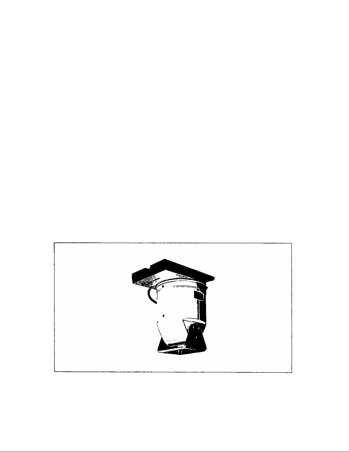
Indoor Pan/Tilt
WV-7230D
Panasonic
Before attempting to connect or operate this product, please read these instructions completely.
Page 2
CONTENTS *
INTRODUCTION ...............................................................................................................................................................................................1
PRECAUTIONS .................................................................................................................................................................................................1
MAJOR OPERATING CONTROLS AND THEIR FUNCTIONS ........................................................................................................................ 2
PRECAUTIONS ON INSTALLATION ................................................................................................................................................................4
INSTALLATION ..................................................................................................................................................................................................4
APPLICABLE CAMERAS, LENSES AND HOUSINGS ......................................................................................................................................5
TYPICAL SYSTEM CONNECTIONS .................................................................................................................................................................6
CONNECTIONS .................................................................................................................................................................................................6
ADJUSTMENTS .................................................................................................................................................................................................8
SPECIFICATIONS ..............................................................................................................................................................................................9
STANDARD ACCESSORIES .............................................................................................................................................................................9
OPTIONAL ACCESSORIES ..............................................................................................................................................................................9
OUTLINE DRAWING ...................................................................................................................................................................................... 10
INTRODUCTION____________________________________________________________
The WV-7230D Pan/Tllt with the WV-CU254 System Controller and WV-RCl 00 Indoor Receiver allows remote control of camera
panning and tilting, the Pan/TIlt can be ceiling mounted or bracket mounted to any flat surface.
The camera can be panned through a total of 340®, and can be tilted through a total of 90° (45® above or below the center
position). Panning speed is 7°/sec., tilting speed is 4®/sec.
PRECAUTIONS_____________________________________________________________
1. Do not attempt to disassemble this unit. There are
rK> user serviceable parts inside. Flefer servicing to
qualified service personnel.
2. Use this unit within its rating.
(a) Designed for indoor use.
Ambient temperature: 14®F - 122®F (-10°C +50°C)
(b) Avoid using this unit when humidity is above 90*/..
3. Do not use this unit in the place which has a high
percentage steam or oil.
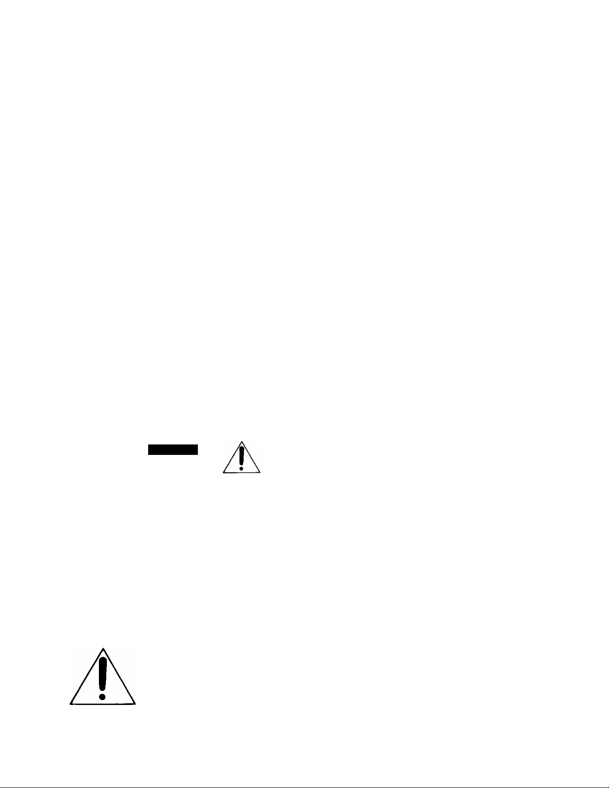
CAUTION
WSK OF ELECTRIC SMOCK
A
CAUTION:
TO REDUCE THE RISK OF ELECTRIC SHOCK, DO
NOT REMOVE COVER (OR BACK). NO USERSERVICEABLE PARTS INSIDE.
REFER SERVICING TO QUALIFIED SERVICE
PERSONNEL.
A
SA 1965
SA 1966
DO NOT OPEN
The lightning flash with arrowhead
symbol, within an equilateral triangle,
is intended to alert the user to the
presence of uninsulated "dangerous
voltage" within the product's
enclosure that may be of sufficient
magnitude to constitute a risk of elec
tric shock to persons.
The exclamation point within an
equilateral triangle is intended to alert
the user to the presence of important
operating and maintenance (servicing)
instructions in the literature accompa
nying the appliance.
4. Select a flat location which can support the entire
weight (panning head, camera, camera housing).
5. The input power source must be 24Vi3o^ (19.2 - 26.4V)
AC 60 Hz for WV-7230B. (Supplied by Indoor Receiver
WV-RC)
6. Use only a low voltage camera (24V AC).
7. Every necessory procedures with regard to install this
product should be made by qualified Service Personnel
or System Installers.
......................................................................................................For U.S.A
Warning:
This equipment generates and uses radio frequency
energy and if not installed and used properly, i.e., in
strict accordance with the instruction manual, may
cause harmful interference to radio communications.
It has been tested and found to comply with the limits
for a Class A computing device pursuant to Subpart
J of Part 15 of FCC Rules, which are designed to pro
vide reasonable protection against such interference
when operated in a commercial environment.
.................................................................................................................... For CANADA
This digital apparatus does not exceed the Class A
limits for radio noise emissions from digital apparatus
set out in the Radio Interference Regulations of the
Canadian Department of Communications.
The serial number of this product may be found on
the bottom of the unit.
You should note the serial number of this unit in the
space provided and retain this book as a permanent
record of your purchase to aid identification in the
event of theft.
Model No._____________________________________
Serial No.
_____________________________________
WARNING:
TO PREVENT FIRE OR SHOCK HAZARD, DO NOT EXPOSE THIS APPLIANCE TO RAIN OR MOISTURE.
- 1 -
Page 3
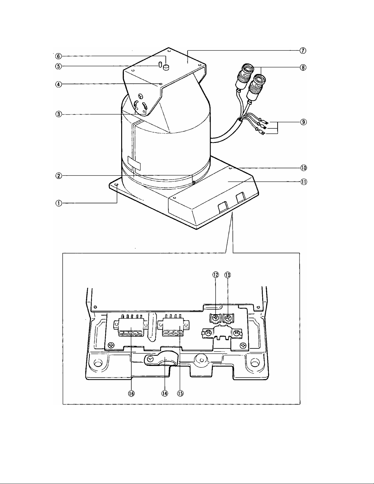
MAJOR OPERATING CONTROLS AND THEIR FUNCTIONS
-2-
Page 4

(I) Mounting Holes
4-5/16’ (4-08)
{2} Pan Limit Stops
Adjustable panning angle: 10° - 340°
(13) External Sync Input Terminal (EXT SYNC)
This terminal is connected with the external sync
generator.
(14) Cable Clamp
(3) Tilt Limit Stops
Adjustable tilting angle:
Up: 0° - 45°, Down; 0° -45°
(4) Camera Housing Mounting Holes
4-03/16" (4-05)
(5) Camera Guide Pin
(6) Camera Mounting Screw
Standard Photographic Pan/Tilt
head Screw (U 1/4’-20UNC}
(7) Mounting Plate
(8) Camera Cables
Those connectors are connected with the Video
Output and Gen Lock Input of the camera,
(9) Camera Power Cables
(10) Cover Screws
(II) Cover
(12) Video Output Terminal (VIDEO)
This terminal is connected with the video input of the
Receiver WV-RC100.
(15) Control Connector - 1 (8 pins]
8 7
6 5
4 3 2 1
Camera
No Connection
No Connection
No Connection
AC Common
AC Common
AC Common
Ground
(16) Control Connector - 2 (10 pins)
10 g 8 7 6
5 4 3
1
2
LEFT
RIGHT
Up
Down
No Connection
No Connection
DC Common
Iris Control
Focus Control
10: Zoom Control
-3-
Page 5

PRECAUTIONS ON INSTALLATION
This pan/tilt unit Model WV-7230D is designed for
indoor use. Avoid mounting it outdoors under the
eaves or any other place there rain or moisture could
be problem.
If panning unit is mounted upside down as shown
below, the image on monitor TV will also be upside
down. Therefore, remove the camera mounting plate
from the top of the camera and attach it to the bottom
of the camera.
INSTALLATION
CAUTION:
The following installation should be made by qualified
service personnel or system installers.
1. Retighten the Cover Locking Screws and remove the
Cover.
A camera with various lenses and a camera housing
(Model WV-7110, 712ÛD and 7130D) can be used.
Select a location where the total weight is sufficiently
support and firmly fix the units onto plywood, gypsum
board, plaster board or concrete. Install the panning
head before mounting the camera on it.
Mount on flat surface - flat ceiling or mounting bracket
Model WV-7030.
Avoid a location which is susceptible to vibration, such
as close to a motor or ventilation fan.
4. Mount the low voltage camera on the Mounting Plate.
If mount the zoom lens, use with the Zoom Lens fixing
plate WV- Q02 or WV-Q03.
Camera
2. When mounting directly to a flat ceiling:
• Make four holes for mounting the Pan/Tilt Head.
(Screws are not provided.)
• Holes in the head are 5/8” (8 mm).
3. When using on the mounting bracket (WV-7030)
• Use four hex head bolts, plain washers,
lockwashers and hex nuts (provided with the
WV-7030) as shown below.
• After wiring, replace the cover.
Hex Nut
Part (No.:XNG6GFMl
Plain Washer
Part (No.:XWG6FNl
Mounting
Bracket
WV-7030
Plain Washer
(Part No.:XWG6FN)
Lock Washer
(Part No.: XWA6BFN}
Hex Head Bolt
(Part No.: XVG6C35FN)
5. Mounting a camera housing (WV-7130D) on the
Mounting Plate.
• Use four hex head bolts (3/16", M4), plain washers
and lockwashers (provided with the WV-7230D)
as shown below.
-4 -
Page 6

6. Mounting a camera housing (WV-7120D) on the Mounting Plate.
• Use four hex head bolts (3/16", M4), plain washers and lockwashers (provided with the WV-7230D) as shown below.
Hex Head Bolt
(Part No.: XVG4C15FN)
Lock Washer
(Part No.: XWA4BFN)
Plain Washer
(Part No.: XWG4FN}
Camera Housing
(WV-7120D)
APPLICABLE CAMERAS, LENSES AND HOUSINGS
A. The recommended combination of the Panasonic camera, lens and housings to WV-7230D is shown in the following table.
Housing
Lens for 1/2'
Camera
2/3" Tube
2/3' CCD WV-CD134
1/2' CCD
WV-1414
WV-1464
WV-1504
WV-1554
WV-CD24
WV-BD404
WV-BL204
WV-CL304
WV-BL604
WV-CL704
Not Used
for 2/3"
CO
CO
T3
f
(D
>
X
Ll
o
0
0
o
0
o o
o 0
o o o
o
0
0
0
0 o
0 0
0
WV-7110
for 1/2" for 2/3’ for 1/2"
CO
m
N
T3
(D
X
ii.
TO
Ll
0
o
o
Ll
0
0
o
T3
o
X
X
1
0>
>
X
X
X
X
X
Xi
WV-7120D
for 2/3'
CO
WV-7130D
for 1/2' for 2/3'
ro
_l
T3
1
(U
>
X
Ll.
■o
o
X
ij_
T3
o
X
LL
0
. 0
0 0
o
X
0 o
0 o
0 0
o
0 o 0
0 o 0 ■ 0 o 0
X
o
0
X
0
o
O o
0 o 0
CO
00
rsj
-J
>
T3
D
X
u.
0
0
0
o
0
O Possible
X Impossible
-5-
Page 7

TYPICAL SYSTEM CONNECTIONS
Mounting Bracket _
wv-7030 r
Pre-wired cable
WV-CA50
CONNECTIONS
Indoor Receiver
WV-RC100
TTX
AC 24V 60Hz
Coax. Cable
<3
System Controller
WV-CUZ54
0000 »
EB
n 3 à
Coax. Cable
Monitor
AC 120V 60Hz
CAUTION:
• The following connection should be made by qualified
service personnel or system installers.
• Make all connections with the power turned OFF.
• Avoid shorting the terminals, as this may blow a fuse.
If the installation is to be upside-down, the Pan Left-Right
and Tilt Up-Down directions will be reversed. This must be
considered when the wiring is done.
In this case, replace 1 and 2 pins of CN1 and CN2.
If the Pre-wired Cable WV-CA50 is used, replace them using
with MOLEX brand tool 57031-6000.
A. Wiring for Pan/Tllt and Motorized Zoom, Focus, Iris
Control
Control Voltage
Control Current
ZOOM TELE -6VDC
WIDE -F6V DC
FOCUS NEAR -6VDC Less than 100 mA
FAR -fev o c
IRIS
OPEN -6VDC
CLOSE -fev DC
B. The Video and Exit Sync. Terminal Board.
1. Wiring precautions:
• Do not bend coaxial cable into a curve who radius
is smaller than 10 times diameter.
• Never staple the cable - not even with circuì
staples.
• Never crush or pinch the cable.
All these will change the impedance of the cable and cause
poor picture quality.
2. Use the following conditions Cable.
Impedance: 75fì
Diameter: <f>S mm or less
Example: RG - 59/U (BELDEN 9259}
3. Wiring:
• Prepare coaxial cable as shown as below.
Fold back
• Connect as follows.
1 Clamp the coaxial cable with Cable Clamp.
2 Fold back the shield
3 Connect the inner conductor.
When using a camera with motorized zoom, focus and
iris, these connections should be made.
Note: Lens control cable should be approx. 39'
to allow sufficient room for PaaTilt.
-6-
Page 8

C. Wiring with the Connection Cable (WV-CA50)
The wire gauge can be determined by the chart below.
The appearance and cord length is shown in the drawing.
The parts name of WV-CA50 is shown in the following.
No.
1
18 wires cable
Parts name
2 14P housing
3 12P housing
4 10P housing
5 8P housing
6
Contact
7 BNC connector
• The system should be operated by 24V AC and the
power consumption should have less than 11W for the
camera.
Model
Copper wire gauge AWG No.
AWG size
#24
Impedance
(fì/km)
77.9 ft 30
m 10
#22
50.4 ft 50 100
WV-7230D
Cable length
11
13
65
15
m 15 30
#20 32.3 ft
80 155
m 20 45
#18
19.9 ft 130 250
m 40
70
• Cable assembly:
Strip back the cable jacket approx. 0.1 inch and
separate the individual conductors.
D. In case of using the accessory connectors
(MX5557P08 and MX5S57P10)
Select a multi-conductor cable which meets FR-1 rating
with 11 or 13 wires cables for WV-7230D.
12 wires cable is used to extend the cable lengt^
Connect the 11 or 13 wires cable to the following positions
of the accessory connectora
CN Pin No.
WV-7230D
Usage of Terminal Power Source
CN1-1 LEFT 24 V AC
CN1-2
RIGHT
CN1-3 UP
CN1-4
Down
CN2-1 24V AC Camera
CN2-5{6)(7) AC Common
CN1-7 DC COMMON 24V AC Common
CN1-8
Iris Control
±6V DC Common
CN1-9 Focus Control ±6V DC
CN1-10 Zoom Control
CN2-8 Camera Ground
• If 13 wires cable are available for WV-7230D, connect
the remainded 2 wires to the ( ) positioa
1 1
9 £
10
5
Ï 7
6
4 ;
1
Ï 2
CN1
8 7 6 5
4
2
3
CNZ
1
Approx.
Contact
^^3
0.1 inch
Up >
^ Insert
Insert the wire until A position
and clamp the contacts.
Wire
2
Preparate the individual cortductors for clamping.
If clamping, use MOLEX brand tool part number
57027-5000 (for UL-Style Cable UL1015 or
57026-5000 (for UL-Style cable UL1007).
After clamping the contacts, push them into the proper
holes in the connector housing until they snap in place.
Up
Î
Contact
Wire
CAUTIONS:
Shrinking the cable-entry seal is a one-time procedure.
DO NOT shrink the cable-entry seal until it has been
ascertained that the unit is functioning.
CONNECT THIS TO 24V AC CLASS 2 POWER SUPPLY
ONLY.
Caution: To prevent fire or shock hazard,
the UL listed wire VW-1, style 1007
should be used for the cable for 24V
AC Input Terminals.
The accessory connectors view from wiring side.
-7-
Page 9

Zoom Control Connector
The control connector of the motorized zoom lens should
be a 4- pin connector, Hirschman type Mas 4100. If it is
not, substitute the existing connector with the Mas 4100
supplied, according to the following diagram:
1. DC COM
2. IRIS
3. FOCUS
4. ZOOM
Push here for removing
Case
Clamp
rv
Lens Control
Cable
Motorized
Zoom Lens
ADJUSTMENTS
Camera Power Cable
Connect the spade lug connectors to the 24V AC Power
Terminal Strip of the lowvoltage camera, according to the
diagram.
Camera Cable
Connect the Camera Cable to the video output connector
of the lowvoltage camera.
CAMERA
CAUTION:
The following adjustments should be made by qualified
service personnel or system installers.
After the cable is assembled and the unit Is connected, plug
the Remote Control Unit into a 120V AC source and proceed
as follows.
A. Panning Angle
Loosen the Pan Limit Stops.
Press on the ON/OFF Switch ON to energize the unit,
then rotate Pan/Tilt Head using the joystick Pan/Tilt
Control unit the desired right pan limit is reached.
Locate the right pan limit stop and move until it
3.
contacts limit switch inside the Pan/Tilt Head. Move
stop additional slight amount until a 'clock” is heard
indicating opening of limit switch. Lock the stop in
place.
4.
Rotate the Pan/tilt Head to the desired left limit position.
Adjust the left pan limit stop as was done for the right
limit stop.
5. With both limit stops in place, pan to both stop positions
and recheck for exact positioning of limit stops, tighten
both stops securely.
B. Tilting Angle
Loosen the recessed two Tilt Limit Stops and rotate
Pan/Tilt Control until desired upward limit is reached.
Move the upward limit stop toward the bottom of the
slot until a "clock" can be heard. Tighten screw.
Adjust the downward limit stop the same way.
Lock the limit stops securely inplace after checking for
exact positioning.
Front
Down : Max. 45*
-8-
Page 10

SPECIFICATIONS
System controller:
Indoor Receiver:
Mountable housing:
Power Consumption:
Panning:
Panning angle:
Tilting speed:
Tilting angle:
Lood weight:
Operating ambient temperature:
Dimensions (inch; Approx.):
Weight:
STANDARD ACCESSORIES
WV-CU254 (Optional)
WV-RC100 (Optional)
WV-7130D, 7110, 7120D (Optional)
Approx. 30W Max.
Automatic or Manual (Selectable)
10° - 340° (Adjustable)
Approx. 4°/sec
Up: approx. 45°, Down: Approx. 45'
Less than 17-1/2 lbs (8 kg)
14°F- 122°F(-10°C--|-50°C)
6-7/16"{W) X 10"(H) X 8-1/8"(D)
[163(W) X 252(H) x 226(D) mm]
Approx. 14.5 lbs (6.5 kg)
Mounting screws for camera housing
[Part No.: WVG4C15MF]
Plane washer
[Part No.: WEG4FN] ......................................................... 6pcs.
Lock washer
[Part No.: XWA4BFN] ....................................................... 6pcs.
4pin connector for Zoom Lens
[Part No.: YWMAS4100] ...................................................... ipc.
Connector
[Part No.: MX5557P10]
MX5557P06] ..................................................... 1pc.
.....
............................................
....
.................................................. 1pc.
6pcs,
OPTIONAL ACCESSORIES
Pre-wired Cable
.......................................................
WV-CA50
-9-
Page 11

OUTLINE DRAWING
3E
-10-
Page 12

Panasonic
Communications & Systems Company
Panasonic Communications & Systems Company
Division of Matsushita Electric Corporation of America
CLOSED CIRCUIT VIDEO EQUIPMENT DIVISION
HEADQUARTERS:
50 Meadowland Parltway, Sacaucus, New Jersey 07094
EASTERN ZONE:
50 Meadowland Parkway. Secaocus. NJ 07094 (201) 348-7620
CENTRAL ZONE;
425 E. Algonquin Road. Arlington Hts. IL 60005 (706) 9B1-4826
SOUTHERN ZONE:
Dallas Region: 4500 Amon Carter Btvd., Ft Worth. TX 76155 (817) 685-1117
Atlanta Region: 1654 Shackleford Ct, Suite 115. Norcross, GA 30093 (404) 925-6841
WESTERN ZONE:
Seattle Region: 1200 Westlake Ave. N.. Suite 506. Seattle. WA 96109 (206) 285-6883
Los Angeles Ftegion: 6550 Katella Ave., Cypress. CA 90630 (714) 373-7275
MATSUSHITA ELECTRIC OF CANADA LIMITED
5770 Ambler Drive, Mississauga. Ontario, Canada L4W 2T3 (416) 624-5010
PANASONIC SALES COMPANY
DIVISION OF MATSUSHITA ELECTRIC OF PUERTO RICO, INC.
San Gabriel Industrial Park, 65th Infantry, Ave. KM. 9.5 Carolina, Puerto Rico 00630 (809) 750-4300
N1109-0
V8QA2023AN
Printed in Japan
® 13
 Loading...