

Page 1

2012 LCD TV Technical Guide
ET5, DT50 and WT50 Series-LCD HD/FHD TV
Applies to models:
TC-L47DT50
TC-L55DT50
TC-L42E50
TC-L47E50
TC-L55E50
TC-L42ET5
TC-L47ET5
TC-L55ET5
TC-L47WT50
TC-L55WT50
Title Page
Panasonic National Training
Panasonic Consumer Marketing Company of North America
TTG120627JM120716
1
Page 2

Warning
Prepared by
Jean Magloire
Panasonic Consumer marketing Company of North america
National Training
"HDMI, the HDMI logo and High-Definition Multimedia Interface are trademarks or registered trademarks of HDMI Licensing LLC.“
Copyright 2012 by Panasonic Consumer Marketing of North America
All rights reserved. Unauthorized copying and distribution is a violation of law.
Warning
This service information is designed for experienced repair technicians only and is not designed for use by the
general public. It does not contain warnings or cautions to advise non-technical individuals of potential dangers in
attempting to service a product. Products powered by electricity should be serviced or repaired only by
experienced professional technicians. Any attempt to service or repair the product or products dealt with in this
service information by anyone else could result in serious injury or death.
2
Page 3
Table of Contents
Subject Page Subject Page
Features 6 TC-L47DT50 Board Layout 29
Highlights 7 Stand by/Start-up Operation (P/A board) 30
The New World of Smart VIERA 8 Start up operation 31
Concept of the IPTV World 9 Start up operation _ A board (SUB voltages) 32
Evolution of the IPTV World and Its Future Expansion 10 Start up operation _ A board (OVP circuit) 33
2D-3D Conversion 11 Start up operation _ A board (PNL,FRC voltage) 42
2012 Series/Models 12 TC-L47ET5 Connector Voltages) 44
WT50 Series 13 Video signal processing 45
DT50 Series 14 Video Process 46
ET5 Series 15 TC-L47ET5 Upper LVDS Connector 48
E50 Series 16 Panel Free Run Mode 49
E5 Series 17 Video Process - Difference from last year model 50
U5 Series 18 Panel Drive 51
X5 Series 19 47WT50 & 47DT50 LED Backlight Control 52
C5 Series 20 DT50 LED Backlight Control Connectors 53
3D Eyewear Standardization 21 55WT50 & 55DT50 LED Backlight Control 57
DT50 or WT50 Back Cover and Dongles 23 Troubleshooting Shutdown Problem 59
Bluetooth 24 Troubleshooting SOS Protection Circuit 60
Bluetooth Module & WIFI Module Confirmation 25 Troubleshooting 1 Blink of the Power LED (ET5 Series) 61
Warning about 3D Eyewear 26 Troubleshooting 1 Blink of the Power LED (WT & DT Series) 62
Viewing 3D images 27 Troubleshooting 3 Fast Blinks of the Power LED 64
TC-L42ET5 Board Layout 28 Troubleshooting 7 Blinks of the Power LED 65
3
Page 4

Table of Contents
Subject Page Subject Page
Troubleshooting 9 Blinks of the Power LED (ET 5 Series) 66 Vertical Area Picture Problem 80
Troubleshooting 9 Blinks of the Power LED (DT & WT Series) 67 Vertical Line/Bar Problem 81
Troubleshooting 10 Blinks of the Po wer LED 68 Horizontal Line Picture Problem 82
The Power LED Remains in Standby Mode 69 Non-uniform Color Picture Problem 83
The LED backlight does not turn on 70 Many Vertical Lines Picture Problem 84
3D Method 71 OSD Problem 85
Relation of 3D TV to Eyewear 74 Strange Color Problem 86
TC-L47ET5 Service Mode 75 Data Copy by SD Card 87
How to Enter the Service Mode’s SRV-TOOL 76 Data Copy Preparation 88
TC-L47ET5 How to Enter the Self-check Mode 77 Data Copy from the TV to SD Card 89
Troubleshooting Picture Problem 78 Data Copy from the SD Card to TV 90
Horizontal Area Picture Problem 79 Glossary (1) 91
4
Page 5

Topics
1. Features
2. Start-up Operation
A) Stand by Operation
B) Power On Operation
C) Voltage Distribution
3. Signal process Circuit
A) Video Signal
B) Audio Signal
4. SOS Detect
5. Service Notes
A) Service Mode
B) SRV-TOOL
C) Self check
6. Troubleshooting
7. Data Copy Function (SD card)
7. Glossary
5
Page 6

Features
Features
6
Page 7
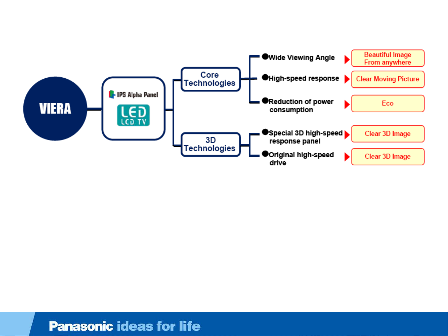
Highlights
7
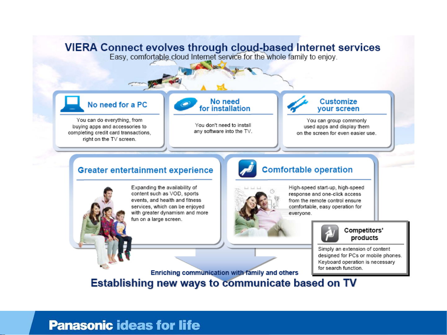
Page 8
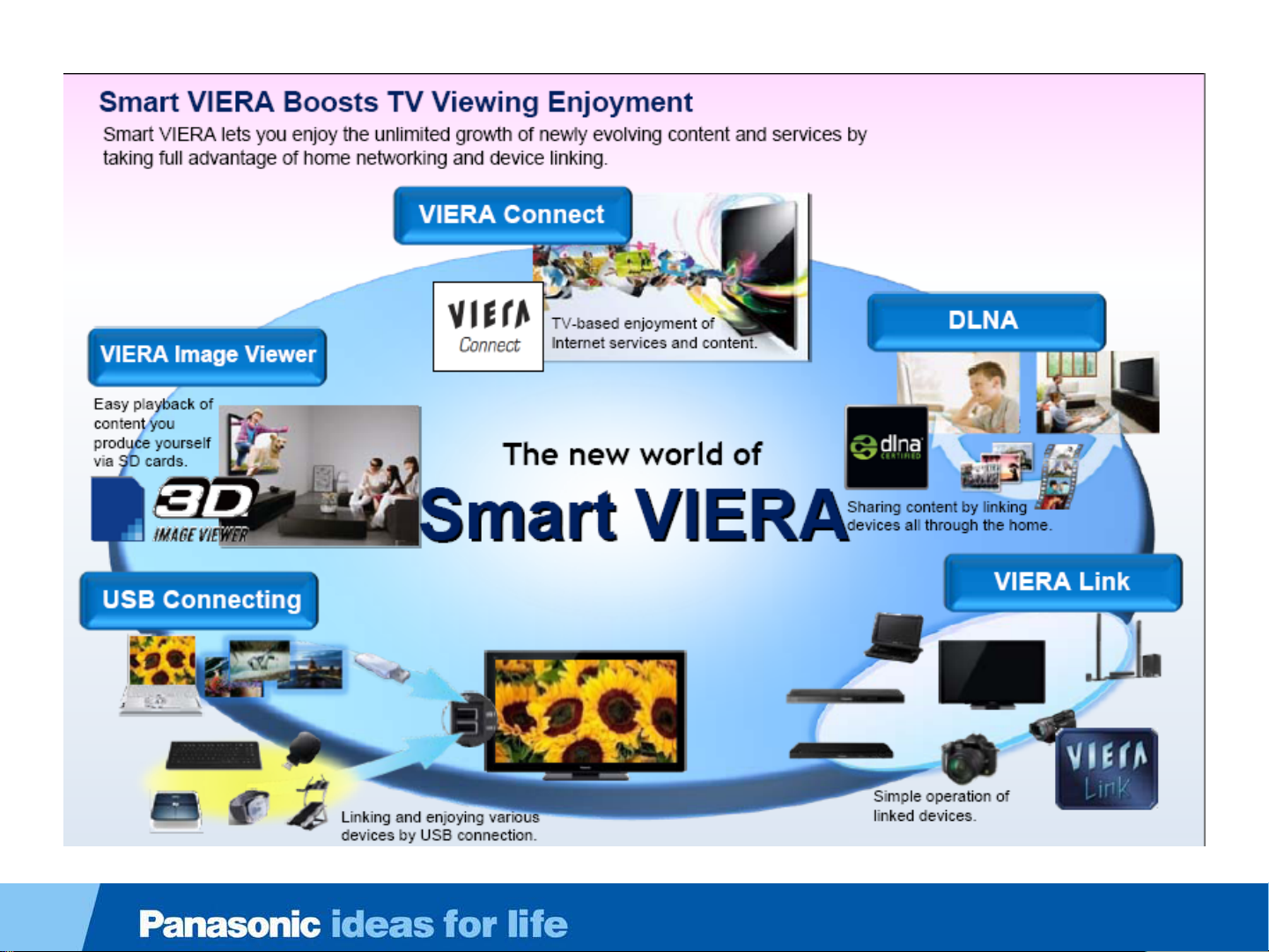
The New World of Smart VIERA
8
Page 9

Concept of the IPTV World
9
Page 10
Evolution of the IPTV World and Its Future Expansion
10
Page 11
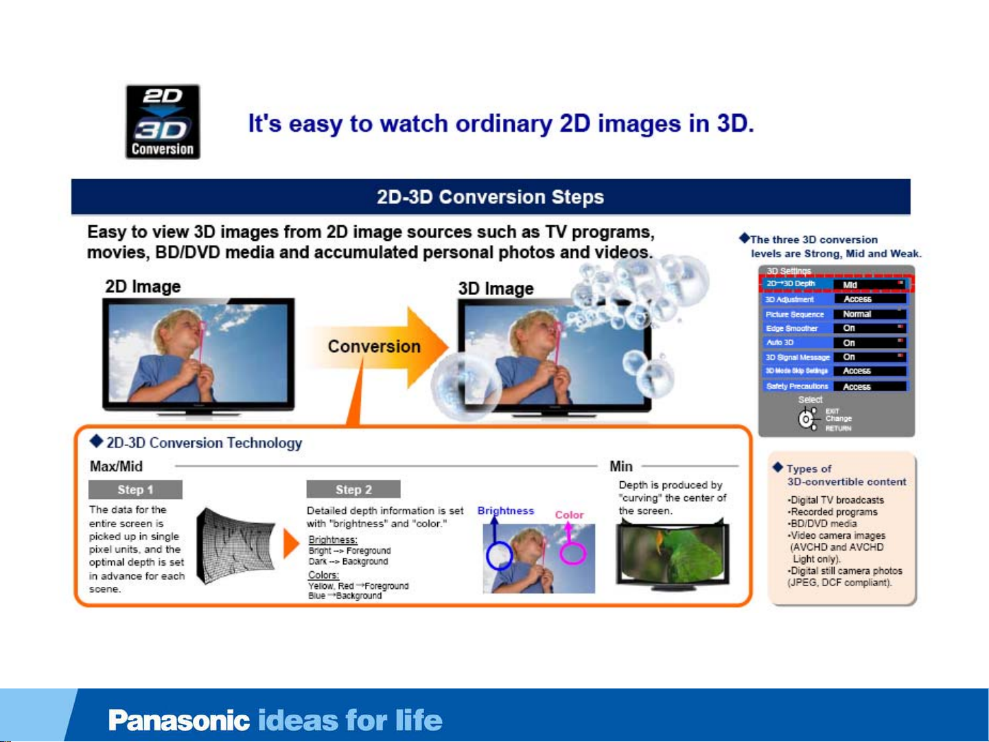
2D-3D Conversion
11
Page 12

2012 Series/Models
Series/Size 55” 47” 42” 37” 32” 24”
WT50 Series
LED -FHD-3D
DT50 Series
LED-FHD-3D
ET5 Series
LED-FHD–3D
E50 Series
LED-FHD
E5 Series
LED-FHD
U5 Series
CCFL-FHD
X5 Series
LED-HD
C5 Series
CCFL-HD
TC-L55WT50 TC-L47WT50
TC-L55DT50 TC-L47DT50
TC-L55ET5 TC-L47ET5 TC-L42ET5
TC-L55E50 TC-L47E50 TC-L42E50
TC-L47E5 TC-L42E5 TC-L37E5 TC-L32E5
TC-L42U5
TC-L32X5 TC-L24X5
FHD
TC-L32C5
12
Page 13
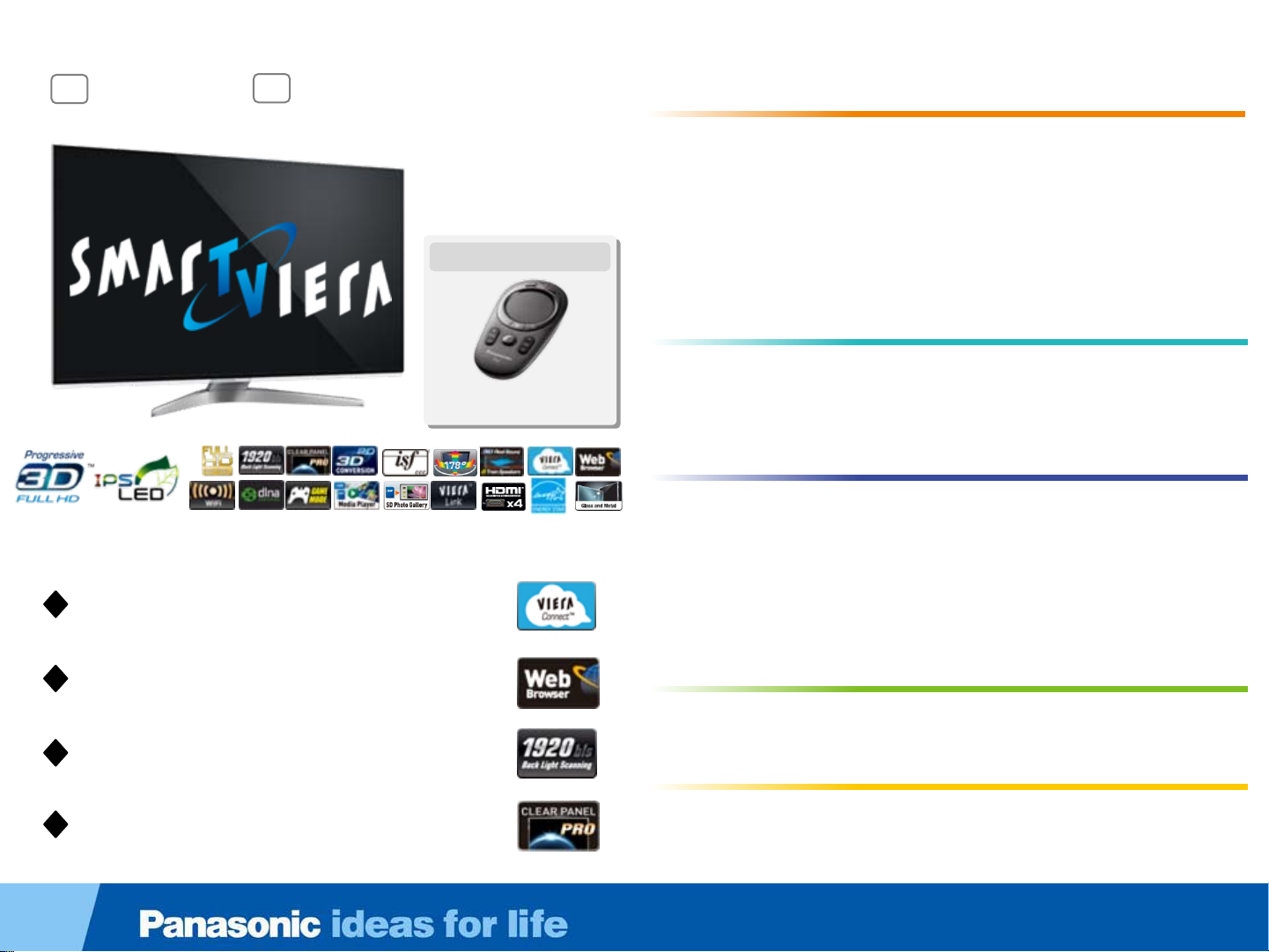
WT50 Series
55
TC-L55WT50
TM
VIERA Connect
VIERA Connect
Web Browser
Web Browser
1,920 Backlight Scanning
1,920 Backlight Scanning
Clear Panel Pro
Clear Panel Pro
47
TC-L47WT50
Included Accessories
VIERA Touch Pad Controller
• VIERA Connect
• Web Browser
• WiFi Built-In
• DLNA
• Game Mode
• 3D Media Player*
• SD Photo Gallery
• Progressive FULL HD
3DTM*
• IPS LED LCD Panel
• 1,920 Backlight Scanning
• Clear Panel Pro
• 1,080p Pure Direct
• Pure Image Creation
• Vivid Color Creation
• VIERA remote App Support
• VIERA Touch Pad
Controller Included
• Energy Star*
•Eco Mode
• Super-Narrow Metal Frame
with Crescent Stand
Picture Quality
Picture Quality
• Web Smoother
• 2D-3D Conversion*
• 3D 24p Cinema Smoother
• ISFccc Calibration Mode*
• Wide Viewing Angle
• 3D Real Sound with 8-Train
Speakers
Easy Operation
Easy Operation
• Multitasking
• Product Support Center
/eHELP
Networking
Networking
• VIERA Link™
• 4 HDMI Terminals
• 3 USB Terminals
• PC Input Terminal
Eco
Eco
Design and Others
Design and Others
13
Page 14

47
55
TC-L55DT50
TM
VIERA Connect
VIERA Connect
TC-L47DT50
DT50 Series
• Progressive FULL HD
3DTM*
• IPS LED LCD Panel
• 1,920 Backlight Scanning
• Clear Panel Pro
• Vivid Color Creation
• VIERA remote App Support
• Product Support Center / eHELP
• VIERA Connect
• Web Browser
• WiFi Built-In
• DLNA
• Game Mode
• 3D Media Player*
• SD Photo Gallery
Picture Quality
Picture Quality
• Web Smoother
• 2D-3D Conversion*
• 3D 24p Cinema Smoother
• Wide Viewing Angle
• 3D Real Sound with 8-Train
Speakers
Easy Operation
Easy Operation
Networking
Networking
• VIERA Link™
• 4 HDMI Terminals
• 3 USB Terminals
• PC Input Terminal
Eco
Eco
Web Browser
Web Browser
1,920 Backlight Scanning
1,920 Backlight Scanning
Clear Panel Pro
Clear Panel Pro
• Energy Star*
•Eco Mode
• Narrow Metal Frame
Design and Others
Design and Others
14
Page 15

ET5 Series
55
TC-L55ET5
VIERA Connect
VIERA Connect
Web Browser
Web Browser
47
TC-L47ET5
TM
42
TC-L42ET5
Included Accessories
Four pairs of 3D Eyewear
(Polarized 3D)
TM
• 3D
• IPS LED LCD Panel
• 360 Backlight Scanning
• Clear Panel
• Vivid Color Creation
• 2D-3D Conversion*
• 3D 24p Cinema Smoother
• Wide Viewing Angle
• 3D Real Sound
• VIERA remote App Support
• Product Support Center / eHELP
• VIERA Connect
• Web Browser
• WiFi Built-In
• DLNA
• Game Mode
• 3D Media Player*
• SD Photo Gallery
with Polarized 3D
• VIERA Link™
• 4 HDMI Terminals
• 2 USB Terminals
• PC Input Terminal
Picture Quality
Picture Quality
Easy Operation
Easy Operation
Networking
Networking
Eco
Eco
WiFi Built-In
WiFi Built-In
360 Backlight Scanning
360 Backlight Scanning
• Energy Star*
•Eco Mode
• Crystal Frame
Design and Others
Design and Others
15
Page 16
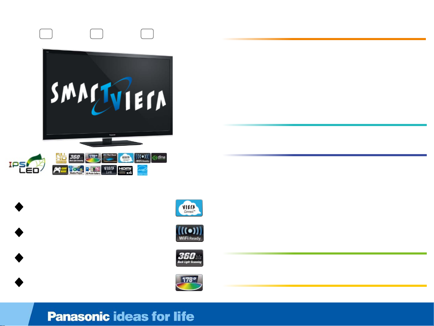
E50 Series
55
TC-L55E50
TM
VIERA Connect
VIERA Connect
WiFi Ready
WiFi Ready
47
TC-L47E50
42
TC-L42E50
• FULL HD
• IPS LED LCD Panel
• 360 Backlight Scanning
• Clear Panel
• Vivid Color Creation
• 24p Cinema Smoother
• Wide Viewing Angle
• 3D Real Sound
• VIERA remote App Support
• Product Support Center / eHELP
• VIERA Connect
• WiFi Ready
• DLNA
• Game Mode
• Media Player*
• SD Photo Gallery
• VIERA Link™
• 4 HDMI Terminals
• 2 USB Terminals
• PC Input Terminal
Picture Quality
Picture Quality
Easy Operation
Easy Operation
Networking
Networking
360 Backlight Scanning
360 Backlight Scanning
Wide Viewing Angle
Wide Viewing Angle
• Energy Star*
•Eco Mode
Eco
Eco
Design and Others
Design and Others
16
Page 17

E5 Series
47
TC-L47E5
42
TC-L42E5
TM
Online Movies
Online Movies
37
32
TC-L37E5
TC-L32E5
• FULL HD
• IPS LED LCD Panel
• 180 Backlight Scanning
• Clear Panel
• Vivid Color Creation
• Wide Viewing Angle
• 3D Real Sound
• VIERA remote App Support
• Online Movies
• WiFi Ready
• DLNA
• Game Mode
• Media Player*
• Energy Star*
•Eco Mode
1
Picture Quality
Picture Quality
Easy Operation
Easy Operation
Networking
Networking
• SD Photo Gallery
• VIERA Link™
• 4 HDMI Terminals
• 2 USB Terminals
• PC Input Terminal
Eco
Eco
WiFi Ready
WiFi Ready
180 Backlight Scanning*
180 Backlight Scanning*
Wide Viewing Angle
Wide Viewing Angle
• AV Surround
1
Only for the L47/42/37E5
Design and Others
Design and Others
17
Page 18
42
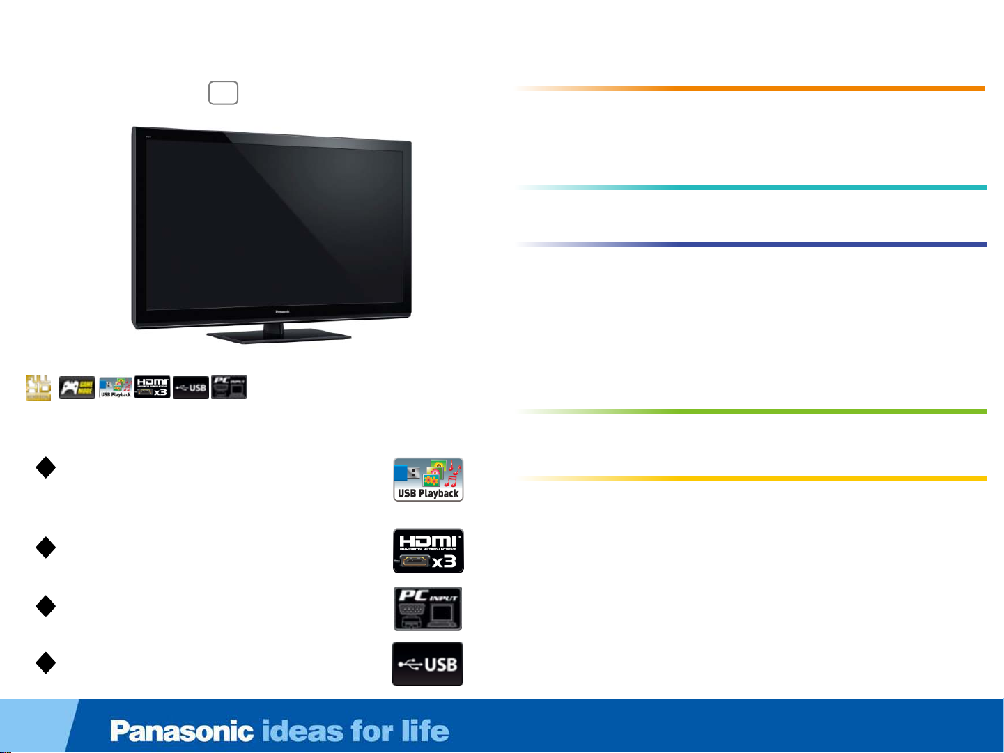
TC-L42U5
U5 Series
• FULL HD
• 24p Playback
• Simple Remote Control
• Game Mode
• Media Player*
(USB Playback/ Photo and Music)
• 3 HDMI Terminals
• 1 USB Terminal
• PC Input Terminal
• Eco Mode
Picture Quality
Picture Quality
Easy Operation
Easy Operation
Networking
Networking
Eco
Eco
Media Player*
Media Player*
(USB Playback/ Photo and Music)
(USB Playback/ Photo and Music)
3 HDMI Terminals
3 HDMI Terminals
PC Input Terminal
PC Input Terminal
1 USB Terminal
1 USB Terminal
• AV Surround
Design and Others
Design and Others
18
Page 19

X5 Series
Picture Quality
32
TC-L32X5
TM
24
TC-L24X5
• FULL HD
• IPS LED LCD Panel
• 24p Playback
• Wide Viewing Angle
• Simple Remote Control
• Game Mode
• Media Player
• SD Photo Gallery
• 3 HDMI Terminals
• 1 USB Terminal
• PC Input Terminal
• Energy Star
• Eco Mode
1
2
2
3
2
2
2
1
Picture Quality
Easy Operation
Easy Operation
Networking
Networking
Eco
Eco
2
Media Player
Media Player
Wide Viewing Angle
Wide Viewing Angle
SD Photo Gallery
SD Photo Gallery
3 HDMI Terminals
3 HDMI Terminals
2
2
2
2
2
Design and Others
Design and Others
• AV Surround
2
2
1
Only for the L24X5
2
Only for the L32X5
3
L24X5 is only USB Memory
19
Page 20

32
TC-L32C5
C5 Series
• HD Panel
• 24p Playback
• Simple Remote Control
• Game Mode
• Media Player*
(USB Playback/ Photo and Music)
• 2 HDMI Terminals
• 1 USB Terminal
• PC Input Terminal
• Eco Mode
Picture Quality
Picture Quality
Easy Operation
Easy Operation
Networking
Networking
Eco
Eco
Media Player*
Media Player*
(USB Playback/ Photo and Music)
(USB Playback/ Photo and Music)
2 HDMI Terminals
2 HDMI Terminals
PC Input Terminal
PC Input Terminal
1 USB Terminal
1 USB Terminal
• AV Surround
Design and Others
Design and Others
20
Page 21

2012 3D Eyewear
21
Page 22
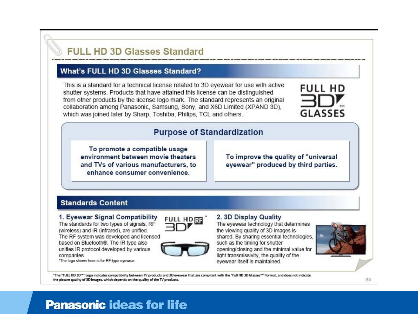
3D Eyewear Standardization
22
Page 23
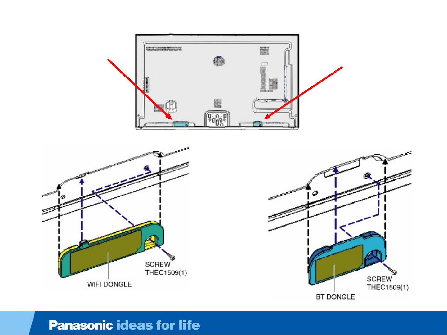
DT50 or WT50 Back Cover and Dongles
WIFI Dongle
Bluetooth Dongle
23
Page 24

Bluetooth
The 3D eyewear used on the 2012 TVs support Bluetooth wireless technology.
Standard Compliance Bluetooth® 3.0
Frequency Range 2.402GHz~2.480GHz
Web Browser
The Web Browser supports HTML5 pages.
You can browse the internet much like you do with a PC.
24
Page 25

Bluetooth Module & WIFI Module Confirmation
Self-check Screen
SELF-CHECK
PEAKS OK
TUN OK
STBY OK
MEM1 OK
MEM2 OK
ZWEI OK
ID OK
HDMI-SW OK
BT 01
WIFI ___
SOS: 01
Copyright Panasonic Corporation 2012
0A
1.030 – 00.12.0846
Cell Phone Usage
A cell phone may be used to detect the TV’s
Bluetooth transmission. The name “Panasonic
Viera” is displayed on the cell phone when the 3D
Bluetooth signal is discovered.
Note: Not all iPhones and smartphones are
capable of discovering the Panasonic Bluetooth
signal. The self-check procedure on the left is
most reliable.
To access the self-check screen, simultaneously
hold down the Volume Down button of the TV
and the OK button on the remote control for a few seconds.
The absence of the Bluetooth and WIFI module are indicated
as follows:
Bluetooth = Error 01 in Red
WIFI = Long dash in red
25
Page 26

Warning about 3D Eyewear
Do not use 3D bluetooth transmission in hospital or other medical facilities.
Radio waves from 3D bluetooth transmission may cause interference of medical
equipments.
Do not use 3D bluetooth transmission nearby automatic control equipments, like a
automatic door, a fire alarm apparatus, etc.
Radio waves from 3D bluetooth transmission may cause interference of automatic
control equipments.
Keep 3D bluetooth transmission more than 22 cm (9 in.) away from the implant of
cardiac pacemaker, or similar implantable medical equipments, at all times.
Radio waves from 3D bluetooth transmission may affect implantable cardiac
pacemaker or similar equipment operations.
26
Page 27

Viewing 3D images
Types of 3D signal that can be displayed by this TV
1. A 3D Blu-ray disc, played on 3D capable Blu-ray player/recorder
that is connected via HDMI cable.
2. 3D TV broadcast (program)
3. 3D Photo and 3D Movie taken by LUMIX/Camcorder.
4. 3D game played on 3D capable video game console, connected
via HDMI cable.
27
Page 28

TC-L42ET5 Board Layout
Board Name Function
GK-Board Power Switch, Key
P-Board Power Supply
K-Board Remote Receiver , LED, Cat's eye
A-Board Main Board
28
Page 29

TC-L47DT50 Board Layout
P2
A02
P
A12A
LD1
P4
LD2
A
LD
LD4
LD3
T-CON
Board Name Function
A15
A10
A20
A21
LP-Board Panasonic Logo LED
P-Board Power supply, Power switch, Control Button
K-Board LED, Cat's eye
A-Board Main Board
LD LED Drive
29
Page 30

Stand by/Start-up Operation (P/A board)
Stand by/Start-up Operation (P/A board)
30
Page 31

Start up operation
When the TV is plugged in, the power board outputs 5V for standby power. Upon receiving this voltage, the
micro (IC8000) outputs the TV_SUB_ON command.
When the power supply receives the TV_SUB_ON signal, it outputs 2 different voltages:
•P15V to the A board on pins 1, 2, and 3 of connector P2.
•24V to the LED backlight power board on pins 7, 8, and 9 of connector P4. This voltage is not used at plug-in.
When the power-on button is pressed and the A board is ready to turn on the display, IC8000 of the A board
outputs the Backlight-on command to LCD Module.
31
Page 32

Start up operation _ Step 1
32
Page 33

Start up operation _ Step 1
When the TV is plugged in, the rectifier circuit produces a DC voltage that
travels through the PFC circuit directly to the power switches Q7301 and
Q7302. A separate DC voltage, approx. 40V, produced by D7104 and D7105
serves as start-up voltage to pin 1 of the oscillator IC7301. When the voltage on
pin 1 rises up to a predefined value, IC7301 starts to oscillate and output
switching pulses to Q7301 and Q7302. As current flows through the winding of
T7301, output voltages are generated by the transformer. One of these
voltages, VCC, is used to power pin 10 of IC7301 .
When the power supply starts up, 6V is created by D7407/C7514. This voltage
goes to IC7502 which is a 5V regulator. The start command for this regulator
originates at pin 3 of IC7301.
This pin is internally grounded in normal state and the information is carried to
the secondary side by PC7303. Finally there is around 2.4V on pin 3 of IC7502
to start its operation. Then 5V is output at pins 1 and 2 of the IC.
This voltage (STB5V) is provided to the A board via pin 5 of connector P2.
So when the TV is plugged in, STB5V is provided to A board without an external
trigger signal.
33
Page 34

Start up operation _ Step 2
34
Page 35

Start up operation _ Step 2
The STB5V from pin 5 of connector P2 is applied to the Analog ASIC (IC5000) to
supply power to the Main CPU/PEAKS LD4 (IC8000) on the A board. The Analog
ASIC (IC5000) converts the STB5V to STB3.3V and STB1.2V. These 2 voltages
energize and prepare the microprocessor (CPU) for program execution. The STB3.3V
from the Analog ASIC (IC5000) is also applied to the remote control receiver and the
power LED on the K board through pins 5 and 10 of connector A10.
Upon energizing, IC8000 automatically outputs the TV _SUB_ON command for approximately 12
seconds. This command triggers the output of the P15V source (not shown in the drawing) to the A
board, but the red LED does not light.
The A board performs a self-check operation to determine its communication status. If a defect is
encountered, the unit shuts down and possibly displays a blink code. If all is well, the unit goes to the
standby mode.
When the power on command from the power switch, the remote control receiver or Viera Link
is provided to IC8000 PEAKS LD4, the “TV_SUB_ON” command (2.4V) is output. The
“command is provided to the power supply board via pin 7 of connector P2.
35
Page 36

Start up operation _ Step 3
36
Page 37

Start up operation _ Step 3
When the power board receives the TV_SUB_ON signal from IC8000 via pin 7 of connector P2, it outputs 2
different voltages:
1.P15V to the A board on pins 1, 2, and 3 of connector P2.
2.24V to the LED backlight power board on pins 7, 8, and 9 of connector P4.
This command is carried to the primary side of the power supply by PC7302. This voltage turns on the
transistor Q7303 to provide a reference voltage from pin 6 to pin 5 of IC7301.
Therefore the operation of IC7301 changes the switching frequency from standby state to increase the output
voltages.
The TV_SUB_ON command also turns on Q7202 to provide power and turn on the PFC circuit. As a result,
the PFC starts to operate and the output voltages from the transformer T7301 start to rise until the moment
IC7401 starts to operate. This IC monitors the 16V output on the secondary side of the power supply. The
output of IC7401 is provided to pin 4 of IC7301 by PC7301. IC7301 adjust the switching frequency by this
feedback signal. The circuit is designed to maintain a stable DC output of the power supply.
The TV_SUB_ON signal also switches on the transistors Q7402 and Q7403 to output the P15V and 24V
output voltages to other boards.
The 24V is provided to the LCD Module ( LED Backlight Power Supply).
The P15V is provided to the A board.
37
Page 38

Start up operation _ A board (SUB voltages)
38
Page 39

Start up operation _ A board (SUB voltages)
The P15V from the P board enters the A board via pins 1, 3 and 5 of connector A02. It is applied to
the Analog ASIC IC5000 and other ICs (Voltage regulators) to generate the SUB-Voltages used for
signal processing operation.
The SUB1.1V, 1.5V, 1.8V, 3.3V, 5V, HDMI3.3V and USB5V are created.
Each voltage regulator is activated by a DCDCEN command created from the P15V source.
So the presence of the P15V source on the A board causes each of the SUB-voltage regulator ICs
to output a DC voltage.
39
Page 40

Start up operation _ A board (OVP circuit)
40
Page 41

Start up operation _ A board (OVP circuit)
The Sub voltages are monitored for over-voltage condition. If any of these voltages increases above a
predetermined level, the OVP circuit will be triggered by getting pin 7 of IC5000 to go high.
When pin 7 goes high, the TV_SUB_ON voltage connected to pin 8 is grounded. This disables the circuit that
generates the P15V and 24V on the power supply.
If any abnormality occurs with P15V, the DCDCEN circuit inside IC5000 provides a DC output to turn on the
switch at pin 11. This in turn disables the output of the SUB-Voltage regulator ICs (IC5400, IC5420, IC5440,
IC8100 and IC8101).
When an over voltage condition is detected at plug-in the TV becomes completely disabled and the power
LED remains off.
When an over voltage condition is detected at power-on the TV becomes completely disabled and the power
LED remains on.
41
Page 42

Start up operation _ A board (PNL,FRC voltage)
42
Page 43

Start up operation _ A board (PNL,FRC voltage)
The P15V is also used to generate the PNL-Voltage and FRC-Voltages on the A board. IC5000
outputs the Panel VCC On2 signal. IC5300 uses this command to generate the PNL12V.
The PNL12V is provided to the T-con circuit of the LCD Module and ICs (Voltage regulator) to
produce FRC-Voltages.
After that, IC8000 outputs the BL_ON command to the LCD Module through the P board. The BL_ON
command turns on the LED backlight power supply of the LCD Module. If the backlight power circuit
does not work normally, the BL_SOS signal communicates this information to IC8000. At that time,
IC8000 stops outputting the TV_SUB_ON signal and blinks the red power LED 1 times.
43
Page 44

TC-L47ET5 Connector Voltages)
Connector P4
PIN # NAME VOLTS OHMS
1 PWM 1.5V 3.1K
2 BL_ON 3.1V 255K
3 BL_SOS 0V 56K
4 GND 0V 0
5 GND 0V 0
6 GND 0V 0
7 24V 23.98V 1.4K and
Rising
8 24V 23.98V 1K and
Rising
9 24V 23.98V 1K and
Rising
Connector P2
PIN # NAME VOLTS OHMS
1 16V 15.9V 23K
2 16V 15.9V 23K
3 16V 15.9V 23K
4 GND 0V 0
5 5V 5.3V 40K
6 GND 0V 0
7 SUB-ON 2.4V 6.3K
8 POWER-ON 3.2V 18.4K
9 KEY 3.2V 15.6K
10 BL-SOS 0V 55K
11 BL-ON 3.1V 255K
10 POWER_ON 3.2V 18.4K
11 KEY 3.2V 15.6K
12 GND 0V 0
12 NC 0V 0
13 BL-PWM1 1.4V 3.1K
14 NC 0V 0
15 GND 0V 0
44
Page 45

Video signal processing
Video Signal Processing
45
Page 46

Video Process
46
Page 47

Video Process
The main function of the A board is to select and process one of the incoming video
signals. IC8458 and IC4700 are switches that select USB and HDMI signals. The built-in WiFi
module is connected using a USB type terminal.
Video input, Component Video Input, composite video output of the tuner and the other HDMI input
are all connected to IC8000 for selection. The IC has interface circuits that converts each input
signal into digital RGB . The data selected for viewing is then provided to the RGB process circuit
within the same IC for processing.
The RGB Process section of the IC performs all picture control operations such as
brightness, contrast, color, tint, etc. On Screen Display data such as channel numbers,
Digital TV closed caption, and picture adjustments are mixed with the video data. After the
process, LVDS (Low Voltage Differential Signaling) is output to IC9100. IC9100, the FRC
(Frame Rate Converter) IC doubles or triples the frame rate to improve focus and eliminate blur.
The output signal is provided to the T-CON for display on the LCD screen.
47
Page 48

TC-L47ET5 Upper LVDS Connector
Upper LVDS connector
A disconnected upper LVDS
connector (TC02A) results in
distorted video. The picture appears
to be in the background with vertical
white line in front.
When troubleshooting a distortion of
this type, if the LVDS connector is in
place, use the internal pattern
Panasonic
generator to determine if the problem
is in the A board or the T-CON. A
normal T-CON generates pictures that
are clean and smooth. Keep in mind,
the T-Con is part of the panel. It
cannot be replaced in the field.
Lower LVDS connector
When the lower LVDS connector (TC01A) is disconnected, The screen is dark blue with no video.
use the internal pattern generator to determine if the problem is in the A board or the T-CON. A
normal T-CON generates pictures that are clean and smooth. Keep in mind, the T-Con is part of
the panel, it cannot be replaced in the field.
48
Page 49

Panel Free Run Mode
When a picture problem is encountered, the internal test pattern generator
may be used to determine whether the symptom is the result of a defective A board or panel.
The test pattern is displayed as follows:
All video sources
contain distortion
Start the Panel
Free Run
Feature
Yes
Did the test
patterns display
correctly?
A-Board
No
Panel
49
Page 50

Video Process - Difference from last year model
50
Page 51

Panel Drive
LED
DRIVER
CONTROL
T-CON
B
A
C
K
L
I
G
H
T
LCD PANEL
A16
1-9
57
56
59
19-47
54-55
P12V
PWM_ENB
DISPEN
BT LR
LVDS DATA
IIC
A
P12V
PANEL_
VCC_ON
IC8000
Peaks
PRO4
1,3,5
P2A02
1,2,3
SMPS
P15V
P
IC9500
LED
DRIVER
I
C
9
5
0
1
I
C
9
5
0
2
LD
LD3
1-20
LD1
LD2
1. The panel_VCC_ON command turns on the panel 12V regulator to power the T-CON circuit.
2. The PWM_ENB command turns on the PWM generator to produce the control signal for the LED backlight
circuit.
3. The DISPEN command turns on the T-CON circuit to produce the column and row signals to drive the panel.
4. Since the T-CON determines the panel’s drive signals, the Bluetooth Left and Right signals are generated for
transmission to the glasses.
5. The LVDS data is the video signal used by the T-CON to produce the column and row signals to drive the
panel.
6. The IIC data is the communication line between the T-CON and the Main CPU. Data for the PWM signal is also
provided through the IIC line.
7. The LED Driver Control signals, using customer’s OSD, CATS, or artificial intelligence, manipulate the
backlight .
51
Page 52

P
47WT50 & 47DT50 LED Backlight Control
LLC Power
LLC Power
Module
Module
LLC TRANS
LLC TRANS
Voltage Detect
P2
12
11
10
3D_ON
BL_ON
BL_SOS
LD
DC Power
LD2
1 15 2 16
LCD Panel
VLED (66Vdc)
16 FETs
Current
Source
P4
LD4
FET
10 9 6 4 2
1 2 5 7 9 10
LD1
LED Backlight
LCD Driver
16V
60
3 17 1 15
FB BL_ONBL_
2-3 61 1
LED DriverIC9500
1
SOS
LD3
T-CON
LED
Driver
Control
4 18
?
?
?
?
?
IIC
PWM_EN
LVDS
TX
A15
54-55
57
19
47
52
Page 53

47WT50 & 47DT50 LED Backlight Control
The LED driver board receives 66Vdc and 16Vdc from the power supply via connector P4/LD4. The 16V source is used
to bias the drive IC, IC9500. The 66V source is used bias the LED. The backlight_On command from the same
connector starts the inverter drive signals.
The BL_SOS connection originates at IC8000, the system control IC located on the A board. IC8000 monitors the status
of BL_SOS line to determine the state of the LED drive circuit. During normal operation, IC9500 pulls the BL_SOS line
low to inform IC8000 of the illumination of the LED. Should the drive circuit or an LED array inside the panel become
defective, the BL_SOS line remains or goes high to inform IC8000 of the condition. The TV shuts down and the power
LED emits a one blink error code.
The LED drive circuit is responsible for delivering the current needed to illuminate the panel’s LEDs. A total of 16 FETs
are manipulated on/off by grounding pulses generated within IC9500. To adjust the brightness, the pulses are modulated
to control the on and off time of the FETs.
Unlike other models, a PWM_EN command is provided to the T-CON by the system control IC. The actual PWM signals
are communicated via the IIC bus line of IC8000. The PWM signals are provided to the LED drive circuit via the
connector LD3.
The 66Vdc source and grounding pulses are delivered to the LEDs via t he connectors LD1 and LD4.
When the TV is displaying 3D images, the 3D_ON command is output from IC8000 to change the 66Vdc source of the
power supply to 84Vdc.
Note:
Connector LD1 or LD2 disconnected = Brief (2 seconds) operation with video and sound , then shutdown with one blink
of the power LED
Connector LD1 and LD2 disconnected = Brief operation with black screen and sound , then shutdown with one blink of
the power LED
Connector LD4 Disconnected = Brief operation with black screen and sound , then shutdown with one blink of the
power LED
Connector LD3 Disconnected = Brief operation with black screen and sound , then shutdown with one blink of the
power LED
53
Page 54

47DT50 & 47WT50 LED Backlight Control
CN LD1
Pin # Label Plug-in Power-on 3D ON Ohm
1 NC 0V 0V 0V Infinite
2 NC 0V 0V 0V Infinite
3 LED8 ~28V ~5.2V ~31V Infinite
4 VLED 76V 66V 84V 28K
5 LED7 ~28V ~5.2V ~31V Infinite
6 VLED 76V 66V 84V 28K
7 LED6 ~28V ~5.2V ~31V Infinite
8 VLED 76V 66V 84V 28K
9 LED5 ~28V ~5.2V ~31V Infinite
10 VLED 76V 66V 84V 28K
11 LED4 ~28V ~5.2V ~31V Infinite
12 VLED 76V 66V 84V 28K
13 LED3 ~28V ~5.2V ~31V Infinite
14 VLED 76V 66V 84V 28K
CN LD2
Pin # Label Plug-in Power-on 3D ON Ohm
1 LED16 ~28V ~5.2V ~31V Infinite
2 VLED 76V 66V 84V 28K
3 LED15 ~28V ~5.2V ~31V Infinite
4 VLED 76V 66V 84V 28K
5 LED14 ~28V ~5.2V ~31V Infinite
6 VLED 76V 66V 84V 28K
7 LED13 ~28V ~5.2V ~31V Infinite
8 VLED 76V 66V 84V 28K
9 LED12 ~28V ~5.2V ~31V Infinite
10 VLED 76V 66V 84V 28K
11 LED11 ~28V ~5.2V ~31V Infinite
12 VLED 76V 66V 84V 28K
13 LED10 ~28V ~5.2V ~31V Infinite
14 VLED 76V 66V 84V 28K
15 LED2 ~28V ~5.2V ~31V Infinite
16 VLED 76V 66V 84V 28K
17 LED1 ~28V ~5.2V ~31V Infinite
18 VLED 76V 66V 84V 28K
19 NC 0V 0V 0V Infinite
20 NC 0V 0V 0V Infinite
15 LED9 ~28V ~5.2V ~31V Infinite
16 VLED 76V 66V 84V 28K
54
Page 55

47DT50 & 47WT50 LED Backlight Control
CN LD3
Pin # Label Plug-in Power-on 3D ON Ohm
1 PWMRST8 0V ~22mV ~22mV 1.4M
CN LD3
2 PWMRST7 0V ~22mV ~22mV 1.4M
3 PWMRST6 0V ~22mV ~22mV 1.4M
4 PWMRST5 0V ~22mV ~22mV 1.4M
5 PWMRST4 0V ~22mV ~22mV 1.4M
6 PWMRST3 0V ~22mV ~22mV 1.4M
7 PWMRST2 0V ~22mV ~22mV 1.4M
8 PWMRST1 0V ~22mV ~22mV 1.4M
9 GND 0V 0 0 0
10 PWMCLK 0V 1.6V 1.6V 47K
11 GND 0V 0V 0 0
12 SEL 0V 49mV 28mV 1.5M
13 GND 0V 0V 0 0
14 SDI 44mV 26mV 1.5M
15 GND 0V 0V 0 0
16 SCK 38mV 26mV 1.5M
17 GND 0V 0V 0 0
18 LOAD 0V 22mV 22mV 1.4M
19 GND 0V 0V 0 0
CN 10
LD Board
CN LD3
CN 10
T-CON
20 DVDD 0V 3.2V 3.2V 109
Test Points are provided on the T-CON board.
Note: The pin numbers are reversed.
55
Page 56

47DT50 & 47WT50 LED Backlight Control
CN LD4
Pin # Label Plug-in Power On 3D ON Ohm
1 VLED 76V 66V 84V 28K
2 VLED 76V 66v 84V 28K
3 NC 0V 0V 0V -
4 GND 0V 0V 0V 0
5 16V 16V 16V 16V
6 GND 0V 0V 0V 0
7 FB 2.4V 2.4V 1.7-1.9V 106K
8 GND 0V 0V 0V 0
9 BL_ON 0V 3.3V 3.3V 1M
10 BL_SOS 3.2V 0V 0V 54K
56
Page 57

P
LLC Power
LLC Power
Module
55WT50 & 55DT50 LED Backlight Control
P2
Module
LLC TRANS
LLC TRANS
Voltage Detect
12
11
10
3D_ON
BL_ON
BL_SOS
LD
IC9502
Booster Circuit Booster Circuit LED Driver
DC Power DC Power
LD2
2 16 1 15
LCD Panel
P4
LD4
VLED
Current Source
LED Backlight
LCD Driver
10 9 6 4 2 1
1 2 5 7
16V
IC9501 IC9500
LD1
4 18 3 17
3D_ON BL_ONBL_
Current Source
9
SOS
LD3
IC9500
T-CON
10
LED
Driver
Control
1 20
?
?
?
?
?
IIC
PWM_EN
LVDS
TX
A16
54-55
57
19
47
57
Page 58

55WT50 & 55DT50 LED Backlight Control
The LED driver board receives 66Vdc and 16Vdc from the power supply via connector P4/LD4. The
16V source is used to bias the drive IC, IC9500. The 66V source is used bias the LED. The
backlight_On command from the same connector starts the inverter drive signals.
The BL_SOS connection originates at IC8000, the system control IC located on the A board. IC8000
monitors the status of BL_SOS line to determine the state of the LED drive circuit. During normal
operation, IC9500 pulls the BL_SOS line low to inform IC8000 of the illumination of the LED. Should
the drive circuit or an LED array inside the panel become defective, the BL_SOS line remains or
goes high to inform IC8000 of the condition. The TV shuts down and the power LED emits a one
blink error code.
The LED drive circuit is responsible for delivering the current needed to illuminate the panel’s
LEDs. A total of 16 FETs (Not shown in the drawing) are manipulated on/off by grounding pulses
generated within IC9500. To adjust the brightness, the pulses are modulated to control the on and
off time of the FETs.
Unlike other models, a PWM_EN command is provided to the T-CON by the system control IC. The
actual PWM signals are communicated via the IIC bus line of IC8000. The PWM signals are provided
to the LED drive circuit via the connector LD3.
The 66Vdc source and grounding pulses are delivered to the LEDs via the connectors LD1 and LD4.
When the TV is displaying 3D images, the 3D_ON command is output from IC8000 to trigger the
operation of IC9501 and IC9502. These two ICs are part of booster circuits that amplify the VLED
source from the power supply to a higher level for 3D operation.
Disconnection of connectors yields the same results as the 47DT50 and 47WT50 models.
58
Page 59

Troubleshooting Shutdown Problems
Troubleshooting Shutdown Problems
59
Page 60

Troubleshooting SOS Protection Circuit
LED Blinks Cause Checkpoint
No Light No STB5V detected P/A
1 LED driver: BL_SOS Panel/A/P
Fast 3 Incomplete or interrupted Boot Program execution of PEAKS
7 No voltage SUB3.3V detected A
9 Audio amplifier: SOUND_SOS A/Speaker
10 No PNL12V detected A/Panel
LED remains in
standby mode
P/A
IC8000 ( No P15V)
Over voltage protection P/A
60
Page 61

Troubleshooting 1 Blink of the Power LED (ET5 Series)
LED Blinks Cause Checkpoint
1 LED driver: BL_SOS Panel/A/P
Confirm the connectors CN2,
P4, P2, A02 and the LED Driver
connectors are properly seated.
At power on, is there
24V at pins 7, 8 or 9
of connector P4 before
the shutdown?
No No
P Board
BL_SOS is generated when a malfunction is detected by the backlight power board. A logic High is sent to IC8000 of the A
board via pin 3 of connector P4, pin 10 of connector P2 and pin 4 of connector A02.
- Normal: BL_ON is high (3.3V) in Standby mode , BL_SOS is low (0V) (power On)
-Error :BL_ON is low (0V) in Standby mode , BL_SOS is high (3.3V) ) (power On)
Yes
At power on, is there 3.3V
voltage (BL_ON) at pin 2 of
P4 before the LED blinks?
A Board
Yes
Panel Module
61
Page 62

Troubleshooting 1 Blink of the Power LED (WT & DT Series)
LED Blinks Cause Checkpoint
1 LED driver: BL_SOS Panel/LD/A /P
P
P2
11
10
BL_ON
BL_SOS
A02
6
4
A
IC8000
PEAKS
L
C
D
P
A
N
E
L
LED
LCD
DRIVER
?
?
?
LD1
3-17
1-15
LD2
1-15
2-16
LD3
4-18
VLED
GND
IC9500
Backlight
VLED
GND
LED DRIVER
CONTROL
DRIVER
LD
Power
LED
LD4
1-2
5
9
10
VLED
16V
BL_ON
BL_SOS
P4
9-10
6
2
1
LLC
POWER
MODULE
- Normal: BL_ON is high (3.3V) in Standby mode , BL_SOS is low (0V) (power On)
-Error :BL_ON is low (0V) in Standby mode , BL_SOS is high (3.3V) ) (power On)
BL_SOS is generated when a malfunction is detected by the backlight power board (LD). A logic High is sent to IC8000 of the
A board via pin 10 of connector LD4, pin 1 of connector P4, pin 10 of connector P2 and pin 4 of connector A02.
62
Page 63

Troubleshooting 1 Blink of the Power LED (WT & DT Series)
LED Blinks Cause Checkpoint
1 LED driver: BL_SOS Panel/LD/A /P
Start here
Does the backlight
Momentarily come on
before the TV shuts
down?
No
Disconnect the connector LD4
from the LD board. Using an
approximately 1K to 4.7K resistor,
connect pin 1 (BL_SOS) of
connector P4 to chassis ground.
No
Does the
TV stay on with a
black screen and no
OSD?
No
Confirm the BL_SOS connection
to the A board. Change the A
board if necessary.
Yes
Yes
Use the charts on page 53 to determine if the problem is in the panel or LD board.
At power on,
is there 3V (BL_ON)
at pin 2 of P4 before
the LED blinks?
Yes
At power on,
is there 66V at pins 9 and
10 of connector P4 before
the TV shuts
down?
No
Is there a
short between pin 9 or
10 of connector P4 and
ground?
No
P Board
Determine the location of
the short, P, LD or Panel.
Use page 53 as a
reference.
No
Yes
Yes
Check BL_ON connection
between the P and A board.
Replace the A board if necessary
At power on. Is there
16V at pin 5 of connector
LD4 before the TV shuts
down?
No
Is there a
short between pin 5 of
connector P4 and
ground?
No
P Board
Determine the
location of the
short, P or LD
board.
Yes
LD Board
Yes
63
Page 64

Troubleshooting 3 Fast Blinks of the Power LED
LED Blinks Cause Checkpoint
Fast 3 PEAKS IC does not wake up (no P15V) P/A
Immediately
after plug-in, is there 15V at
pin 1, 2 or 3 of connector A02
before the LED
blinks?
Yes
A Board
No
Disconnect the unit from
the AC outlet
and disconnect the
connector P2.
Is there a short-circuit at
pin 1, 3 or 5 of A02?
Yes
A Board
P Board
P15V is supplied by the P board. If P15V is not available the power LED blinks 3 times (quick
blink).
No
64
Page 65

Troubleshooting 7 Blinks of the Power LED
LED Blinks Cause Checkpoint
7 No voltage SUB3.3V detected A
IC5400 uses the P15V source to produce SUB3.3V.
If SUB3.3V is not detected by IC8000, the LED indicator will blink 7 times. This voltage is only available when
IC5400 is activated by the DCDCEN command sent from IC5000.
This defect can only be caused by the A board.
65
Page 66

Troubleshooting 9 Blinks of the Power LED (ET5 Series)
LED Blinks Cause Checkpoint
9 Audio amplifier: SOUND_SOS A/Speaker
Reconnect the left
speaker wire.
Disconnect
the left speaker wire.
Does the power
LED blink
after power on?
No
L. Speaker
Yes
Disconnect
the right speaker wire.
Does the power
LED blink
after power on?
No
R. Speaker
Yes
A
Board
Does the power
LED blink
after power on?
No
Problem
Solved
L.
Speaker
The audio amplifier is powered by the P15V from the P board. If the amplifier works abnormally due to a short-circuit
or an overload by one of the speakers, the SOUND_SOS signal will go high level and be detected by IC8000. The TV
shuts down and the power LED blinks 9 times.
66
Page 67

Troubleshooting 9 Blinks of the Power LED (DT & WT Series)
LED Blinks Cause Checkpoint
9 Audio amplifier: SOUND_SOS A/Speaker
Reconnect the
left speaker wire.
Disconnect
the subwoofer wire.
Does the
power LED blink
after power
on?
No
Subwoofer
Reconnect the subwoofer and
disconnect the left speaker wire.
Yes
Does the
power LED blink
after power
on?
No
L. Speaker
Yes
Disconnect
the right speaker wire.
Does the
power LED blink
after power
on?
No
R. Speaker
Yes
A
Board
Does the
power LED blink
after power
on?
No
Problem
Solved
L.
Speaker
The audio amplifiers are powered by the P15V from the P board. If the amplifiers work abnormally due to a shortcircuit or an overload by one of the speakers, the SOUND_SOS signal will go high level and be detected by IC8000.
The TV shuts down and the power LED blinks 9 times.
67
Page 68

Troubleshooting 10 Blinks of the Power LED
LED Blinks Cause Checkpoint
10 No PNL12V detected A/Panel
Is there12V at
pin 1-4 of connector TC01A
before the unit shuts down?
Yes
A Board
Using the P15V source, IC5300 produces and regulates the PNL12V. If the voltage PNL12V is not detected,
the unit shuts down and the LED indicator blinks 10 times. This voltage is only available when IC5300 is
activated by the PANEL_VCC_ON command sent from IC8000.
No
Disconnect
the
connector
TC01A.
Is there a short circuit
between pins 1-4 and
ground?
No
Panel Module
Yes
A board
68
Page 69

The Power LED Remains in Standby Mode
LED Blinks Cause Checkpoint
LED remains in standby mode Over voltage protection P/A
Remove the connector P2.
Connect pin 4 to pin 7 of connector P2 to
create pseudo TV_SUB_ON command. Plug
in the power cord.
Is the P15V output at
pin 1, 2 or 3 of connector P2
excessive?
No
A Board
Yes
P Board
If one of regulated voltages (P15V, SUB5V, SUB3.3V, SUB1.5V, SUB1.1V, USB5V) becomes excessive, the OVP circuit
outputs a High to IC5000 to start the shutdown process. The TV_SUB_ON command goes low to place the TV in standby
mode. The power LED indicator turns off. After unplugging and reconnecting the TV to the AC outlet, after power on, the
screen may turn on for a short time and then goes back to standby mode.
69
Page 70

The LED backlight does not turn on
LED backlight does not light up.
At power on, is there
3V (BL_ON) at pin 2
of connector P4?
No No
The BL_PWM signal controls the brightness of the LED backlight. It is a PWM waveform sent by IC8000 of the A board.
This BL_PWM has an amplitude of 3.3V and a frequency of 120Hz.
- In standard picture mode, the average voltage of the BL_PWM signal is about 2.5V (about 80% ON, 20% OFF).
- In vivid picture mode, the BL_PWM signal has a maximum voltage of 3.3V (100% ON).
The BL_PWM voltage varies with brightness, the darker the screen, the lower the BL_PWM voltage.
If the BL_PWM voltage is maximum in vivid picture mode, but the LED backlight brightness is still significantly darker than
that of normal condition, the Panel Module is damaged.
Yes
At power up. Is there
BL_PWM voltage of at pin 1
of connector
P4?
A BoardA Board
Yes
Panel Module
70
Page 71

3D Method
3D Method
71
Page 72

3D Method
72
Page 73

3D Method
73
Page 74

Relation of 3D TV to Eyewear
74
Page 75

TC-L47ET5 Service Mode
How to enter the Service Mode
While pressing [VOLUME ( - )] button of the main unit, press [INFO] button
of the remote control three times within 2 seconds.
Software Version
Picture Adjustment
White Balance Adjustment
Option Setting
Service Tool
SERVICE
ADJUST
WB-ADJ
OPTION
SRV-TOOL
Main Item
ADJUST
CONTRAST 0000
YMAX
Sub Item
Key command
[1] button...Main items Selection in forward direction
[2] button...Main items Selection in reverse direction
[3] button...Sub items Selection in forward direction
[4] button...Sub items Selection in reverse direction
[VOL] button...Value of sub items change in forward direction ( + ), in reverse direction ( - )
How to exit
Turn the television off with the [POWER] button on the main unit or the [POWER] button on the
remote control.
Data
75
Page 76

How to Enter the Service Mode’s SRV-TOOL
How to access
1. Select [SRV-TOOL] in Service Mode.
2. Press [OK] button on the remote control.
S
O
S
H
I
S
T
O
R
Y
Display of SOS (Shutdown) History
SOS History (Number of LED blinks ) indication.
From the left side; Last SOS, before Last, two occurrences before last, 2nd occurrence after shipment, 1st
occurrence after shipment.
This indication except the 2nd and 1st occurrence after shipment will be cleared by reset.
To exit
Disconnect the AC cord from the wall outlet.
76
Page 77

TC-L47ET5 How to Enter the Self-check Mode
How to access:
1. Self-check display only:
While in TV reception mode, press the [VOLUME ( - )] button on the main unit and simultaneously press the [OK] button
on the remote control for 3 seconds or more.
2. Self-check display and forced to factory shipment setting:
While in TV reception mode, press the [VOLUME ( - )] button on the main unit and simultaneously press the [MENU]
button on the remote control for 3 seconds or more.
Self Check Screen
Self Check
PEAKS OK
TUN OK
MEM1 OK
MEM2 OK
FRC OK
ID NG
HDMI-SW OK
WiFi OK
Copyright Panasonic Corporation 2012
How to Exit
Disconnect the AC cord from wall outlet.
X.XXX.XX.XX.XXXX
Panasonic
ROMCORR.CHECKSUM:
**
NG_ or an error code Indicates a defective
part.
When NG is displayed, replace the (A) board.
77
Page 78

Troubleshooting Picture Problem
Troubleshooting Picture Problem
78
Page 79

Horizontal Area Picture Problem
79
Page 80

Vertical Area Picture Problem
80
Page 81

Vertical Line/Bar Problem
81
Page 82

Horizontal Line Picture Problem
82
Page 83

Non-uniform Color Picture Problem
83
Page 84

Many Vertical Lines Picture Problem
84
Page 85

OSD Problem
85
Page 86

Strange Color Problem
86
Page 87

Data Copy by SD Card
Purpose
User settings data, including hotel mode settings data such as channel scan, adjustment data
and factory preset data can be copied to and from an SD card.
A) Board replacement (Copy the data when exchanging A-board):
When exchanging A-board, the data in original A-board can be copied to SD card and then copy to
new A-board.
Before replacing the A
board, copy the EEPROM
data to the SD card.
After replacing the A
A Board
Panasonic
board, copy the EEPROM
data to the A board.
B) Hotel (Copy the data when installing a number of units in hotel or any facility):
When installing a number of units in a hotel or any facility, the data in the master TV can be
copied to a SD card and then copied to other TVs.
A Board A Board
Copy data
to SD card
C
to
y
p
o
m
i
l
n
u
s
V
f T
t o
n
u
o
m
a
d
e
t
i
A Board
87
Page 88

Data Copy Preparation
The SD card requires a startup text file with a “.pwd” extension for copying to the SD card when
replacing the A board or installing a number of units in a hotel.
1. Insert an empty SD card to your PC.
2. Right-click a blank area in the SD card window, point to New, and then click text document. A
new file is created by default (New Text Document.txt).
3. Right-click the new text document that you’ve just created and select “Rename”.
4. Change the name and extension of the file to the following file name for copying to the SD card
and press ENTER.
File name:
(a) For Board replacement : boardreplace.pwd
(b) For Hotel : hotel.pwd
Note:
Please make only one file to prevent operational error.
Do not have any other file on the SD card.
88
Page 89

Data Copy From the TV to SD Card
1. Turn on the TV set.
2. Insert the SD card that contains the startup file
(pwd file) in the SD card slot.
An On-screen display associated with the startup
file will appear automatically.
3. Input the following password for (a) or (b) by using
the remote control.
(a) For Board replacement : 2770
(b) For Hotel : 4850
Data will be copied from the TV set to the SD card.
It takes around 2 to 6 minutes maximum for
copying.
4. After the completion of copying to the SD card,
remove the SD card from the TV.
5. Turn off the TV.
Note:
The following new folder will be created in the SD
card from the TV.
(a) For Board replacement : user_setup
(b) For Hotel : hotel
Data Copy (Board Replacement)
Input Password --------
Panasonic
Data Copy (Board Replacement)
Input Password -------
Panasonic
Data Copy (Board Replacement)
Copy TV to SD Card
Please for a while
Please do not remove SD card
GETTING
Panasonic
Data Copy (Board Replacement)
Data copy has been successful
Please remove SD card
FINISH
Panasonic
Data Copy
Board replacement or
Hotel
Input password
2770
or
4850
Performing
Completion
(i.e. Exchanging
replacement board)
89
Page 90

Data Copy From the SD Card to TV
1. Turn on the TV.
2. Insert the SD card with Data in the SD card slot.
An On-screen display associated with the startup
file will appear automatically.
3. Input the following password for (a) or (b) by
using the remote control.
(a) For Board replacement : 2771
(b) For Hotel : 4851
Data will be copied from the SD card to the TV.
4. After the completion of copying to SD card,
remove SD card from the TV set.
(a) For Board replacement : The data will be
deleted after copying (Limited one copy).
(b) For Hotel : The data will not be deleted and
can be used for other TVs.
5. Turn off the TV.
Note:
1. Depending on the failure of the A board, the
data copy function for board replacement may
not work.
2. This function can be effective among the same
model numbers.
Data Copy (Board Replacement)
Input Password -------
Panasonic
Data Copy (Board Replacement)
Copy SD to TV Card
Please for a while
Please do not remove SD card
WRITING
Panasonic
Data Copy (Board Replacement)
Data copy has been successful
Please turn off the TV for system
initializing
Panasonic
FINISH
(i.e. Exchanging
replacement board)
Input password
2771
or
4851
Performing
Completion
90
Page 91

Glossary (1)
120Hz Motion Picture Pro4
Even fast-moving scenes are displayed sharply and clearly. With a 60Hz video signal input, 120Hz Motion Picture
Pro4 makes 120 frames/second from 60 frames/second. This increases the frame count to allow natural frame-toframe transitions, for smooth motion images with high resolution. Motion Focus Technology also reduces flicker and
effectively suppresses blurring and afterimages.
24P Smooth Film
Enjoy naturally flowing 24p films and familiar TV-like quality. This mode optimizes the number of frames of 24p
images recorded from film media such as a Blu-ray Disc™. Advanced source analysis and frame generation produce
smooth images that are faithful to the original.
Dynamic Contrast Ratio 2000000:1
Both high contrast and energy-saving efficiency have been achieved in the IPS LED LCD TV by combining the IPS
panel, which is known for its wide viewing angle, with a bright, energy-efficient LED backlight. Even dark scenes like
night skies are naturally rendered with delicate shades of black. The Intelligent Scene Controller further boosts the
image quality.
Energy Saving Mode
The entire 2011 VIERA line-up meets the Energy Star 4.0 requirements. VIERA TVs satisfy the new criteria for the
Energy Star program of the U.S. Environment Protection Agency (EPA). This testifies to their top-level energy-saving
performance.
Game Mode
In Game Mode, quicker image response increases the enjoyment of video games when a game console is connected
to the TV. What's more, VIERA produces the dark images in video games more clearly. This mode works with the
anti-image retention (wobbling) function, too.
91
Page 92

Glossary (2)
IPS Liquid Crystal Panel
IPS liquid crystal is an abbreviated expression for In-Plane-Switching type TFT crystal, and is a high quality crystal
mode that "is beautiful even when viewed at an angle." With IPS, the liquid crystal molecules rotate on a plane
parallel to the TFT board by a horizontal electrical field, and therefore in principle, it offers superior viewing angle,
color reproduction, and halftone response speed, has little variation in color tone according to the viewing direction
and is capable of displaying a natural image.
Motion Focus Technology
The VIERA LCD TV detects areas with motion and activates backlight blinking for only those areas, greatly
enhancing resolution.
VIERA Image Viewer
It's easy to view full-HD images with the SD card slot. Watch and show your photos right after you take them. Simply
insert an SD card into VIERA to display photos on the large screen. You can also choose the background music and
display effects. It's much more fun when you can view them on a l arge-screen HDTV with family and friends in 1920 x
1080-pixel high definition and a wide 16:9 aspect ratio.
VIERA Link
VIERA Link™ allows the interlinked operation of various AV devices using only the VIERA remote control, by simply
connecting the devices to each other by an HDMI cable.
VIERA Tools
The VIERA Tools user interface makes it easy to use access key functions by pressing a single button. Functions are
easier to use, and there's no complicated operation. The explanation is displayed when you press the function's
button. Just keep pressing the button to use the function immediately.
•VIERA Tools screen design image is subject to change without notice.
** The screen display varies depending on the model.
TM
TM
92
Page 93

Glossary (3)
Wide Viewing Angle
The wide 178° viewing angle ensures clear images even when viewed from an angle. The backlight's wide
transmission aperture enhances the contrast between light and dark, and improves motion-image response.
HDMI ARC
The HDMI Audio Return Channel (ARC) allows the TV to receive picture and audio signals over the HDMI cable, and
then send the same audio out over the same HDMI cable. ARC is part of the HDMI 1.4 specification.
DLNA
DLNA (Digital Living Network Alliance) is a standard that makes it easy for DLNA-certified equipment to share
multimedia content within a home network. A DLNA-certified media server such as a Windows 7 personal computer
with Windows Media Player 12 is required.
Media content that can be played back using DLNA, SD card or USB memory
Certain JPEG, SD-Video, AVCHD, MP4 files, MKV files, MPEG-2 files, MP3 files, AAC files and LPCM files can be
shared using the DLNA feature. Please see the Owner's Manual for the additional requirements.
USB Port
You can connect flash memory, wireless LAN adapter, keyboard, or mass storage devices to the USB ports on the
TV. Ports are USB 2.0, providing maximum 500mA per port.
Easy IPTV
Easy IPTV provides Internet functionality that allows your TV to access popular movie, music and social networking
sites such as Netflix, Amazon VOD, Napster, Pandora, CinemaNow and Facebook. In order to use Easy IPTV
services, the TV needs to be connected to your home network. Not all IPTV services are available depending on
your country or region. IPTV services are subject to change without notice.
93
 Loading...