

Page 1
Before attempting to connect or operate this product, please read these instructions completely.
The meter bridge shown in photo is one of the optional accessories.
Users’ Guide
Audio Mixer
WR-DA7
Page 2
DA7 Users’ Guide
Table of Contents
Warning:
This equipment generates and uses radio frequency energy and if not installed and used
properly, i.e., in strict accordance with the instruction manual, may cause harmful interference
to radio communications. It has been tested and found to comply with the limits for a Class A
computing device pursuant to Subpart J of Part 15 of FCC Rules, which are designed to
provide reasonable protection against such interference when operated in a commercial
environment.
We declare under our sole responsibility that the product to which
this declaration relates is in conformity with the standards or other
normative documents following the provisions of Directives
EEC/73/23 and EEC/89/336.
Wir erklären in alleiniger Verantwortung, daß das Produkt, auf das
sich diese Erklärung bezieht, mit der folgenden Normen oder normativen Dokumenten übereinstimmt. Gemäß den Bestimmungen
der Richtlinite 73/23/EEC und 89/336/EEC.
Nous déclarons sous notre seule responsabilité que le produit
auquel se référe cette déclaration est conforme aux normes ou
autres documents normatifs conformément aux dispositions de la
directive 73/23/CEE et 89/336/CEE.
Nosotros declaramos bajo nuestra única responsabilidad que el
producto a que hace referencia esta declaración està conforme con
las normas u otros documentos normativos siguiendo las estipulaciones de la directivas CEE/73/23 y CEE/89/336.
Noi dichiariamo sotto nostra esclusiva responsabilità che il prodotto
a cui si riferisce la presente dichiarazione risulta conforme ai
seguenti standard o altri documenti normativi conformi alle disposizioni delle direttive CEE/73/23 e CEE/89/336.
Wij verklaren als enige aansprakelijke, dat het product waarop deze
verklaring betrekking heeft, voldoet aan de volgende normen of
andere normatiefve dokumenten, overeenkomstig de bepalingen
van Richtlijnen 73/23/EEC en 89/336/EEC.
Vi erklærer os eneansvarlige for, at dette produkt, som denne deklaration omhandler, er i overensstemmelse med den følgende standarder eller andre normative dokumenter i følge bestemmelserne i
direktivene 73/23/EEC og 89/336/EEC.
Vi deklarerar härmed värt fulla ansvar för att den produkt till vilken
denna deklaration hänvisar är i överensstämmelse med standarddokument, eller andra normativa dokument som framstölls i Direktiv
73/23/EEC och 89/336/EEC.
Ilmoitamme yksinomaisella vastuullamme, että tuote, jota tämä
ilmoitus koskee, noudattaa seuraavia standardeja tai muita ohjeellisia asiakirjoja, jotka noudattavat direktiivien 73/23/EEC ia
89/336/EEC. säädöksiä.
Vi erklærer oss alene ansvarlige for at produktet som denne
erklæringen gjelder for, er i overensstemmelse med følgende
normer eller andre normgivende dokumenter som fælger bestemmelsene i direktiven 73/23/EEC og 89/336/EEC.
For U.S.A
Page 3
DA7 Users’ Guide
Table of Contents
THIS APPARATUS MUST BE EARTHED.
To ensure safe operation the three-pin plug supplied must be inserted only into a standard three-pin power point which is
effectively earthed through the normal household wiring. Extension cords used with the equipment must be three-core and
be correctly wired to provide connection to earth. Wrongly wired extension cords are a major cause of fatalities.
The fact that the equipment operates satisfactorily does not imply that the power point is earthed and that the installation is
completely safe. For your safety, if in any doubt about the ef fective earthing of the power point, consult a qualified electrician.
For U.K
For Australia
FOR YOUR SAFETY PLEASE READ THE FOLLOWING TEXT CAREFULLY.
This appliance is supplied with a moulded three pin mains plug for your safety and convenience.
A 5 amp fuse is fitted in this plug.
Should the fuse need to be replaced please ensure that the replacement fuse has a rating of 5 amp and that it is approved
by ASTA or BSI to BS1362.
Check for the ASTA mark
H or the BSI mark G on the body of the fuse.
If the plug contains a removable fuse cover you must ensure that it is refitted when the fuse is replaced.
If you lose the fuse cover the plug must not be used until a replacement cover is obtained.
A replacement fuse cover can be purchased from your local Panasonic Dealer.
IF THE FITTED MOULDED PLUG IS UNSUITABLE FOR THE SOCKET OUTLET IN YOUR HOME THEN THE FUSE
SHOULD BE REMOVED AND THE PLUG CUT OFF AND DISPOSED OF SAFELY.
THERE IS A DANGER OF SEVERE ELECTRICAL SHOCK IF THE CUT OFF PLUG IS INSERTED INTO ANY 5 AMP
SOCKET.
If a new plug is to be fitted please observe the wiring code as shown below.
If in any doubt please consult a qualified electrician.
WARNING: This apparatus must be earthed.
IMPORTANT
The wires in this mains lead are coloured in accordance with the following code.
Green-and-yellow: Earth
Blue: Neutral
Brown: Live
As the colours of the wire in the mains lead of this appliance may not correspond with the coloured markings identifying
the terminals in your plug, proceed as follows.
The wire which is coloured green-and-yellow must be connected to the terminal
in the plug which is marked with the letter E or by the earth symbol I or coloured
green or green-and-yellow.
The wire which is coloured blue must be connected to the terminal in the plug
which is marked with the letter N or coloured black.
The wire which is coloured brown must be connected to the terminal in the plug
which is marked with the letter L or coloured red.
How to replace the fuse
Open the fuse compartment with a screwdriver and replace the fuse.
Caution:
Before attempting to connect or operate this product, please read the label on the rear panel.
The serial number of this product may be found on the
rear of the unit.
You should note the serial number of this unit in the
space provided and retain this book as a permanent
record of your purchase to aid identification in the event
of theft.
Model No.
Serial No.
WARNING:
TO PREVENT FIRE OR ELECTRIC SHOCK HAZARD, DO NOT EXPOSE THIS APPLIANCE TO
RAIN OR MOISTURE.
Page 4
DA7 Users’ Guide
Table of Contents
Digital Mixer WR-DA7
Users’ Guide
Version 1.10
Page 5

DA7 Users’ Guide
Table of Contents
Limit of Liability/Disclaimer of Warranty: The author, Audio Video Systems Division of
Matsushita Communication Industrial Co., Ltd has used its best efforts in preparing this
book. However, Audio/Video Systems Division of Matsushita Communication Industrial
Co., Ltd makes no representation or warranties with respect to the accuracy or
completeness of the contents of this book and hereby specifically disclaims any implied
warranties or merchantability or fitness for any particular purpose and shall in no event
be liable for any loss of profit or any other commercial damage, including but not limited
to special, incidental, consequential, or other damages.
TRADEMARKS
Audio Video Systems Division of Matsushita Communication Industrial Co., Ltd has made
every effort to supply trademark information about company names, products, and
services mentioned in this document. Trademarks indicated below were derived from
various sources. All products or services not listed below are the trademarks, service
marks, registered trademarks or registered service marks of the respective owners.
ADAT is a registered trademark of Alesis Corporation
TDIF is copyrighted by TEAC Corporation and TASCAM is a registered trademark of TEAC
Corporation
IBM is a registered trademark of International Business Machines Corporation
Mac is a registered trademark of Apple Computer, Inc.
Page 6
Table of Contents
DA7 Users’ Guide
Table of Contents
Digital Mixer WR-DA7
Users’ Guide
Table of Contents
1. Introduction 1-1
1-1 A New Beginning 1-1
1-2 About This Manual 1-4
1-3 Making the DA7 Work For You 1-7
2. DA7 Tour 2-1
2-1 Overview 2-1
2-2 Top Panel 2-3
2-3 Display Bridge 2-20
2-4 Rear Panel 2-25
3. Quick Start 3-1
3-1 Module A, Getting Sound Out 3-3
3-2 Module B, Onboard Signal Processing 3-6
3-3 Module C, Outboard Processing 3-9
3-4 Module D, Monitoring 3-16
3-5 Module E, Tips, Shortcuts and Warnings 3-17
4. Cursor Control 4-1
5. Channel, Library, and Meter Windows 5-1
5-1 Overview 5-1
5-2 Channel Window 5-3
5-3 Library Windows 5-12
5-4 Meter Group Windows 5-17
5-5 Channel Window, Multi-Channel View 5-20
Page 7

Table of Contents
DA7 Users’ Guide
Table of Contents
6. Fader Layers and Channel Strips 6-1
6-1 Fader Layers 6-1
6-2 Channel Strip 6-3
7. Equalizer 7-1
7-1 Overview 7-1
7-2 Equalizer Section 7-3
7-3 Equalizer Window 7-6
7-4 Equalizer Library Window 7-8
7-5 Equalizer Window, Multi-Channel View 7-10
8. Pan/Assign, Surround, Bus Assign 8-1
8-1 Pan/Bus Assign Controls 8-1
8-2 Surround Window 8-3
8-3 Surround Window, Multi-Channel View 8-12
9. Dynamics/Delay 9-1
9-1 Overview 9-1
9-2 Dynamics/Delay Section Controls 9-3
9-3 Dynamics Window 9-6
9-4 Dynamics Window, Multi-Channel View 9-13
9-5 Dynamics Library Window 9-15
10. AUX 10-1
10-1 Overview 10-1
10-2 AUX Section Controls 10-3
10-3 Fader Control Window 10-5
11. MIDI 11-1
11-1 MIDI, Setup Window 11-1
11-2 MIDI, PRG ASGN (Program Assign) Window 11-6
11-3 MIDI, CTRL ASGN (Control Assignment) Window 11-8
11-4 MIDI, BULK (Bulk Out) Window 11-10
11-5 MIDI, Remote Windows 11-14
Page 8

Table of Contents
DA7 Users’ Guide
Table of Contents
12. D-I/O (Digital Input/Output) 12-1
12-1 D-I/O, Input Set Window 12-2
12-2 D-I/O, To Slot Window 12-10
12-3 D-I/O, Dither Window 12-14
13. Group 13-1
13-1 Overview 13-1
13-2 FADER GRP (Fader Group) Window 13-3
13-3 MUTE GRP (Mute Group) Windows 13-5
13-4 LINK/STR (Stereo) Window 13-7
14. Automation 14-1
14-1 Automation, Setup Window 14-2
14-2 Automation, Execute Window 14-5
14-3 Automation, EVT EDIT (Event Edit) Window 14-14
14-4 Automation Operation 14-19
15. Scene Memory 15-1
15-1 RD/WR (Read/Write) Window 15-1
15-2 XFade Time Window 15-5
16. Utility and Solo Monitor 16-1
16-1 Utility, Solo/Monitor (SOLO/MON) Window 16-2
16-2 Utility, Oscillator/Battery (OSC BATT) Window 16-6
16-3 Utility, Configuration (CONFIG) Window 16-9
16-4 Utility, User Custom (USER CSTM) Window 16-12
17. Options 17-1
17-1 ADAT Digital I/O Card, WR-ADAT 17-2
17-2 TDIF (TASCAM Digital Audio Interface) Card, WR-TDIF 17-5
17-3 AES/EBU & S/PDIF Card, WR-AESS 17-7
17-4. AD/DA Card, WR-ADDA 17-8
17-5 SMPTE Card, WR-SMPT 17-9
17-6 TANDEM Card, WR-TNDM 17-11
17-7 METER BRIDGE 17-16
17-8 MAX, Expansion Software 17-17
Page 9

Appendixes
Appendix A, Setup Scenarios A-1
Appendix B, LCD Screen Displays B -1
Appendix C, Abbreviations and Acronyms C-1
Appendix D, Default Settings D -1
Appendix E, Cables and Connections E-1
Appendix F, Technical Specifications F-1
Appendix G, MIDI Implementation Chart G-1
Glossary
Index
Table of Contents
DA7 Users’ Guide
Table of Contents
Page 10

DA7 Users’ Guide
1-1
1
Introduction
1-1 A New Beginning
The Digital Mixer WR-DA7 sets a new standard for affordable automated
digital audio mixing and production. The DA7 has a number of features built
into it that until recently, were the privilege of only high-end production
facilities. Every feature is either directly controlled or just a window away. As
a DA7 user, you’ve made the decision to become part of the future.
Now that you're here, please take some time to review the manual. Keep it
near your DA7 and refer to it when you come across something you don't
understand. Digital mixers offer substantially more features than regular
analog mixers, and there will be a period of time before you are as
comfortable with the DA7 as you are with other mixers.
Like most people, you'll want to play first and then look for those items in
the manual that were unclear. But you should be aware that the DA7 has
many advanced features that may not be immediately apparent to you, and if
you don't read the manual, you could be missing out on features that can
save you time and effort in a session.
It will help your understanding of the DA7 to read this Users' Guide from
cover to cover, but we know you probably won't. It would be beneficial to
you, however, to at least read Chapters 1, 2, 3, 4 and Appendix D, which
will help you get familiar with the basic operations.
Chapter 1
Introduction
Page 11

Functionality
Let's take a moment to preview some of the main features and benefits of the
DA7.
The Fader Layer controls permits you to mix and monitor the 32 inputs, the
6 aux sends and the 6 aux returns, the 8 buses, and the unique
CUSTOM/MIDI layer. By not tying up input channels for outboard effects the
6 dedicated aux return faders provide extra inputs, for a total of 38 audio
inputs.
The DA7 is digitally controlled which allows you to automate all your mixer
functions, from mixing and MIDI parameters, to dynamics and effects.
Multiple LEDs provide instantaneous display of channel/bus/aux assignments,
as well as automation recording status.
The DA7 comes with internal memory to store fifty EQ libraries, fifty
Dynamics libraries, fifty Channel libraries, plus fifty different scene memories.
Using optional software, you can store these memories in a computer and
save an unlimited number of these memories.
5.1 surround sound mixing is built into the DA7 with multiple methods of
surround sound panning available on each channel.
Option cards expand the capabilities of the DA7. For example, the ability to
synchronize to videotape, using the SMPTE interface option card, makes it
easy to score or sweeten for film or television. There are other options that
expand the capabilities of the DA7, including a Meter Bridge, Mixing
Automation eXpansion software (MAX, for both Windows and Mac) and a
Tandem card that connects two DA7's together.
Audio Input/Output option interface cards can be mixed and matched for a
particular project. You can have any type of audio option card installed and
transfer from one format to another without the need of outboard devices.
For instance, you could have an ADAT card and an AES/EBU card and transfer
from your Digital Audio Workstation to your ADAT, or vice versa.
There are four audio Input/Output option cards available: ADAT, TDIF,
AES/EBU - S/PDIF and an Analog card. Any audio card works in any slot.
Chapter 1
DA7 Users’ Guide
1-2
1
Introduction
Page 12

Simplicity
The DA7 is simple to operate, so you will spend less time as an engineer and
more time as an artist. Engineered for ease of use, the Human-Machine
Interface (HMI) provides a variety of ways to access and assign the channel
parameters for your sources. Every channel parameter is displayed on the
320x240 backlit LCD screen, providing a quick visual reference of every
aspect of the mixer setup.
To view the status of the console on a larger screen, use the optional
software package. This software allows you to create custom views of the
DA7 and control the DA7 from your computer. It acts as a library program
for backing up data from the DA7 libraries, and expands the capabilities of
the automation system of the console. See your dealer for more details.
MIDI devices and MIDI remote control for peripheral gear can be controlled
from the DA7.
The Future is Now
The DA7 is ready for computer-controlled digital mixing right out of the box.
Connect it, and start recording. Everyone, from home musician to
professional artists and producers, can now operate in the “Digital Domain”
and create multi-track masterpieces using the DA7.
Chapter 1
DA7 Users’ Guide
1-3
1
Introduction
Page 13

1-2 About This Manual
Document Notes
The first three chapters of the DA7 Users’ Guide provide an introduction to
the system and basic information for the system.
Chapter 1, Introduction
• general information about the Users’ Guide and the system used to
produce the document
• typical installation and usage scenarios for the DA7
Chapter 2, DA7 Tour
• Top Panel overview and a literal look at the Rear Panel connections
setup
• illustrations that are referenced throughout the following chapters of
the Users’ Guide
Chapter 3, Quick Start
• modules designed to familiarize you with a basic understanding of
the features incorporated in the DA7 mixer
Chapters 4-16 each discuss a primary function of the DA7. The information
follows a basic operational sequence. Some of the chapters will be divided
into sections which discuss specific capabilities and/or functions of the
chapter subject.
The sections in Chapter 17, Options describe various system configurations.
The Appendices provide general information groups and detail the mixer’s
technical specifications.
A Glossary providing definitions for information associated with the DA7
precedes the index for this document.
Chapter 1
DA7 Users’ Guide
1-4
1
Introduction
Page 14
Chapter 1
DA7 Users’ Guide
1-5
1
Introduction
Symbols and Conventions Used in this Guide
The DA7 Users’ Guide uses the icons and conventions listed below.
Whenever possible, the way something appears in the Users’ Guide is as it
appears on the DA7.
Numbers in a triangle indicate a sequential step in a process.
Numbers in a circle indicate a list.
Square bullets indicate alternative ways to perform similar tasks
or actions.
Round bullets indicate items or elements in a group.
Text written in bold letters indicates the name of a knob, fader,
button, or element on the Top Panel or the Rear Panel of the
mixer. When panel labeling incorporates a background, the text
will appear on a medium gray background.
Bold upper-case text contained in square brackets indicates the
name of a window or a window area in the LCD.
Color terms presented in italics and parentheses denotes the
literal color of an LED button for a particular action or
condition.
In this document, cursor is used as both a noun and a verb. “Use
the ARROW buttons to move the cursor”, or “Cursor to the OFF
button”.
Text presented on a black background or contained in a border
indicates buttons or elements that perform a function and
appear in the LCD.
This warning symbol alerts you to an action you may want to
avoid or, at least, seriously contemplate before executing.
This tip symbol indicates an important fact, procedure, and/or
other beneficial information for the mixer operation or
performance.
[STEREO]
(color)
cursor
PST
PRE
■
●
GAIN
SUB
1
1
Page 15

Chapter 1
DA7 Users’ Guide
1-6
1
Introduction
The term “area” refers to a window region in the LCD of the Display Bridge
of the mixer.
The term “section” refers to a region on either the Top Panel or the Rear
Panel of the mixer.
The term “soft knob” refers to a knob control in a window area in the LCD.
Page 16
Chapter 1
DA7 Users’ Guide
1-7
1
Introduction
1-3 Making the DA7 Work For You
Although the DA7 has some analog inputs, it should really be thought of as a
digital mixer. Like most equipment, the DA7 comes set with factory defaults,
some of which may or may not provide the kind of operational preferences
you would like. Please refer to Appendix D, Default Settings for a complete
listing of these presets. You can’t change the factory default presets, but
when you have created mixer settings that you like, they can be saved by
making a snapshot of the setup and recording it in SCENE MEMORY. See
Chapter 15, Scene Memory for more information.
As with any new piece of equipment, it may take you a little time to figure it
out. Here are a few things you WILL need to know about the DA7. Please
take a few minutes now to read them. It could save you time in the long run.
BULK BACKUP
One of the first things to think about is saving data. If you’ve already started
using the DA7 straight out of the box for a major recording session, all of the
mixer data for your new million selling CD stored in the DA7 memory, BACK
IT UP!
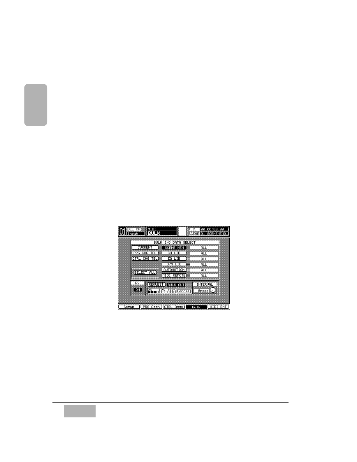
The [MIDI>BULK] window can be accessed by pressing the MIDI button on
the Top Panel. In the [MIDI>BULK] window, you’ll find the [BULK I/O DATA
SELECT] area. All of the information recorded in the system can be sent en
masse to a Mac or IBM compatible computer. See Chapter 11, MIDI, page
11-2, for setting up the serial port output to a personal computer. Some
previous background knowledge of MIDI and a personal computer would be
helpful here. There is software on the market that readily captures bulk
dump information. If you have questions, either visit a local music retailer, or
visit one of a number of Web sites on the Internet for information.
MIDI>BULK Window
Page 17
MASTER RESET
If you’ve already pushed as many buttons as possible after powering up the
DA7 to see what it could do, or if you have accidentally changed any of the
factory presets and cannot figure out what you have done, you need to know
about the master reset command.
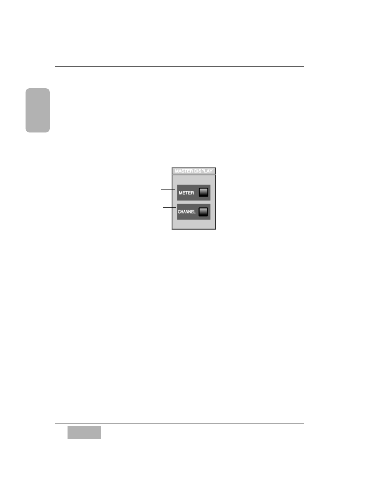
To reset the DA7, turn the power off, and then simultaneously press and
hold the METER and CHANNEL buttons in the MASTER DISPLAY section
of the Top Panel. While pressing these two buttons, turn the power on. Hold
the buttons down until the Channel window is displayed. Doing this will
reset the DA7 to the factory presets.
Also, there are a few windows on the LCD screen that you should acquaint
yourself with, that contain most of the information you need to know about
the current status of your mixer.
They are the [UTILITY>CONFIG], [SOLO/MON], [D-I/O>INPUT SET] and
[MIDI>BULK] windows. Pressing the relevant Top Panel buttons for these
features will display the windows in the LCD. Once you are in any window,
you will find the window group selection buttons on the bottom of the
screen. These buttons show all the windows within the window group. The
window group you are in is indicated on the top line of the [taskbar]. See
Chapter 2, page 2-20 for information on the LCD screen. Cursor to the
bottom of the current window, choose a window selection button, and press
the ENTER button to bring that window into the LCD. You can also access
the selections by pressing the Top Panel button again to toggle through the
selections.
Chapter 1
DA7 Users’ Guide
1-8
1
Introduction
METER
button
CHANNEL
button
MASTER DISPLAY Section
Page 18
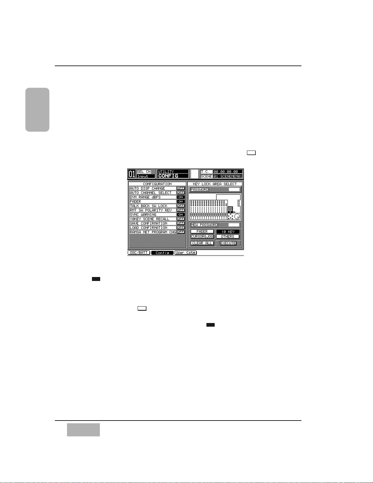
CONFIGURATION
The [UTILITY>CONFIG] window can be accessed by pressing the UTILITY
button on the Top Panel. This is where the [CONFIGURATION] selections
are located. One of the features here is [AUTO CHANNEL SELECT]. When
active, every time a fader is moved or a SELECT button is engaged, whatever
window you are in will change to the [CHANNEL] window for that selected
channel. If you are trying to set up parameters on different Channel Strips,
it could get frustrating to have to go back and forth between windows. To
render this feature inactive, make sure that the button is in the mode.
OFF is the factory preset.
Another [CONFIGURATION] selection is [AUTO DISPLAY CHANGE].
When , whenever a parameter adjustment is made from the Top Panel,
the LCD will change to that parameter window. If you tweek an EQUALIZER,
DYNAMICS/DELAY or PAN knob on the Top Panel, but want to stay in the
[CHANNEL] window, for example, make sure that the [AUTO DISPLAY
CHANGE] selection is . OFF is the factory preset.
Other items in the [CONFIGURATION] area are the [DYN RANGE DBFS]
and [MOTOR FADER] buttons, which are set to as part of the DA7’s
system default.
For more information, see Chapter 16, Utility and Solo Monitor, page 16-
9. Also, see Appendix D for a listing of all the factory default conditions.
ON
OFFONOFF
Chapter 1
DA7 Users’ Guide
1-9
1
Introduction
UTILITY>CONFIG Window
Page 19
Chapter 1
DA7 Users’ Guide
1-10
1
Introduction
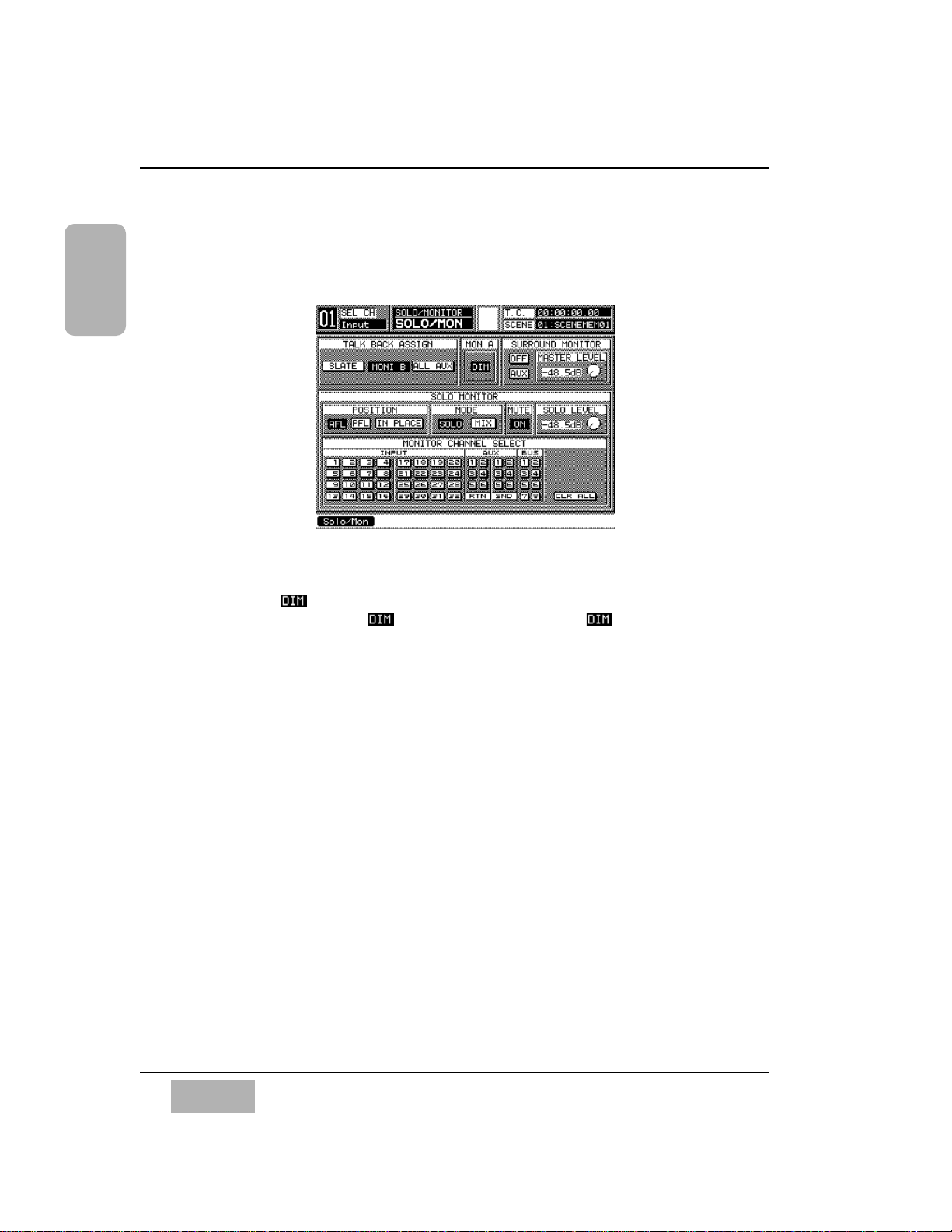
MONITOR SETUP
To customize the monitor setup of the DA7, access the [SOLO/MON] window
by pressing the SOLO MONITOR button on the Top Panel.
The [MON A] area function mutes the MONITOR A speakers 20dB. When
selected, the button will appear in inverse video, and the speakers will
remain dimmed until the button is deactivated. The function can
be accessed from the Top Panel by pressing the MMC/CURSOR button and
SOLO MONITOR button simultaneously.
SOLO is set to [IN PLACE] and [SOLO] in the factory default. This allows
you to only SOLO one channel at a time, post-fader and post-pan. In a mix
situation you may want the [SOLO MONITOR][POSITION] area set to [IN
PLACE], which is post-fader and post-pan, and the [SOLO MONITOR]
[MODE] area set to [MIX], which allows multiple channels to be solo’d.
SOLO MUTE returns the monitor to normal, but leaves the selections of
solo’d channels intact. When SOLO MUTE is cleared, monitoring returns to
the previously selected SOLO channels.
The [SURROUND MONITOR] area mode selection is important too. When
the [SURROUND MONITOR] is in the [AUX] mode, it will send the
surround bus 1 and 2 signals through MONITOR A L/R, while aux sends 3
through 6 route the surround bus 3 through 6 signals. In the [MON] mode,
the surround signal path uses the MONITOR A L/R, MONITOR B L/R, and
MASTER L/R outputs. If the [MON] mode is active, when trying to listen to
another source in the system that is not assigned to the [SURROUND
MONITOR], you will find nothing coming out of the monitor speakers. The
same condition could occur by selecting [SURR] for a channel in the
[CHANNEL] window [ASSIGN] area.
UTILITY>SOLO/MON Window
Page 20
For more information on these windows, see Chapter 16, Utility and Solo
Monitor, page 16-2. To find out about the 5.1 surround sound monitor
output, see page 16-3, and for more on the DA7s’ surround sound features,
see Chapter 8, Pan/Assign, Surround, Bus Assign.
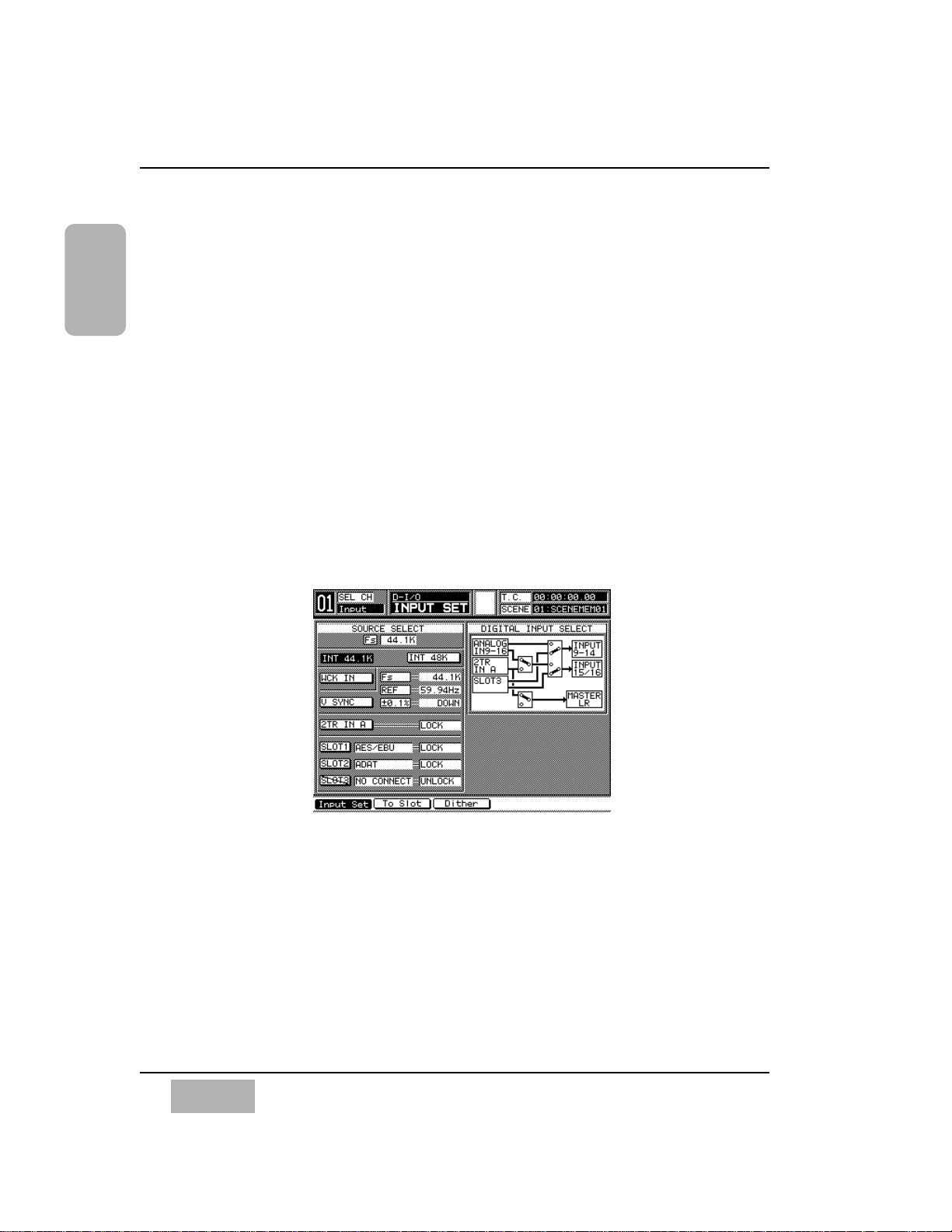
D-I/O INTERFACING
With all the different devices on the market these days, getting all that gear to
speak to one another can be quite a challenge. The DA7 system wordclock is
factory set to [INT 48K], with the option of setting it to [INT 44.1K] or to
external. All digital devices attached to the DA7 must be set to the same
wordclock sampling rate in order to operate properly. If the audio you are
hearing does not sound right, first check to see if you are operating every
device connected to the DA7 at the same sample rate.
Find the sample rate the devices all have in common and set the DA7 to that
rate, be it 44.1, 48K or another acceptable sample rate frequency. To set the
DA7s’ wordclock reference, press the D-I/O button on the Top Panel to
display the [D-I/O>INPUT SET] window.
When using the DA7 as the master wordclock, there are two buttons in the
[SOURCE SELECT] area for setting the sample frequency, [INT 44.1K] and
[INT 48K]. Cursor to the sample frequency that is common to your devices
and press the ENTER button on the Top Panel to engage the appropriate
sample frequency.
Chapter 1
DA7 Users’ Guide
1-11
1
Introduction
D-I/O INPUT SET Window
Page 21

Or, if you prefer to use an external wordclock reference as the master
wordclock, the external wordclock master must output a sample frequency
that is common to all devices. When you are referencing the DA7 to video,
you should be very careful to set the DA7 up properly.
For additional information about sample frequency and setting the clock rate
of the DA7, see Chapter 12, D-I/O, page 12-2.
The key to getting the most out of your DA7 is to learn it completely. We
strongly recommend that you read at least Chapter 2, DA7 Tour, Chapter 3,
Quick Start, Chapter 4, Cursor Control and become familiar with the
factory default presets in Appendix D.
Chapter 1
DA7 Users’ Guide
1-12
1
Introduction
Page 22

DA7 Users’ Guide
2-1
2
DA7 Tour
2-1 Overview
Your tour of the DA7 begins with a brief description of the Human-Machine
Interface (HMI) design concept, and then an introduction to the elements,
functions, and features of the DA7. You may ask, “what is a Human-Machine
Interface (HMI)?”
The HMI is an ergonomic design concept incorporated into most products,
including the DA7 mixer. Literately, it is how you (the human) and the mixer
(the machine) communicate with each other. Using this concept, the DA7
was designed to give you easy access to the hardware and software features
built into the mixer, so that you can quickly learn to use your new DA7 in an
intuitive manner. The layout of these features and how you interact with the
information they give you is described in detail in this manual. This is why
we recommend that you keep this document nearby to use as a reference
tool if you run into any problems.
Shortcuts, unique features and alternative paths of operation are provided to
make using the DA7 faster. They are described throughout this manual, and
pointed out in Chapter 3, Section 3-5. Please read this section carefully. It
will make using the DA7 a more pleasurable experience.
Chapter 2
DA7 Tour
Page 23

Functions and features of the mixer are accessed via knobs, faders, and
buttons on the Top Panel of the DA7. The LCD screen reflects any
adjustments and/or selections you make on the Top Panel. The cursor controls
and the JogDial are both used to navigate the current window displayed or
to make adjustments to the data fields. The LED indicators for the Channel
Strips reflect the channel assignments, and their colors indicate the current
mode.
We know you will develop your own personal style of operation. Once you
become familiar with the proper operation and functions of the DA7,your
level of confidence and ability to operate this digital mixer will surpass
anything you have previously done on a traditional analog console.
Chapter 2
DA7 Users’ Guide
2-2
2
DA7 Tour
Page 24
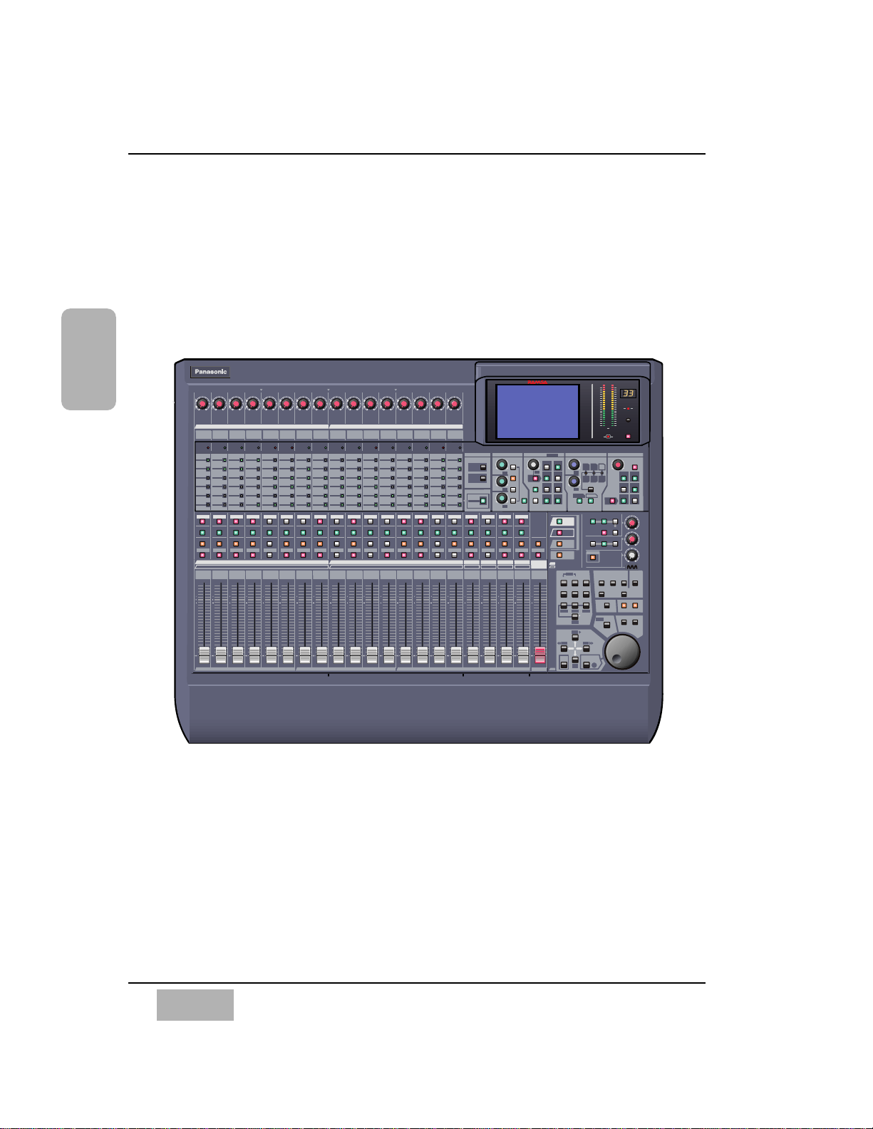
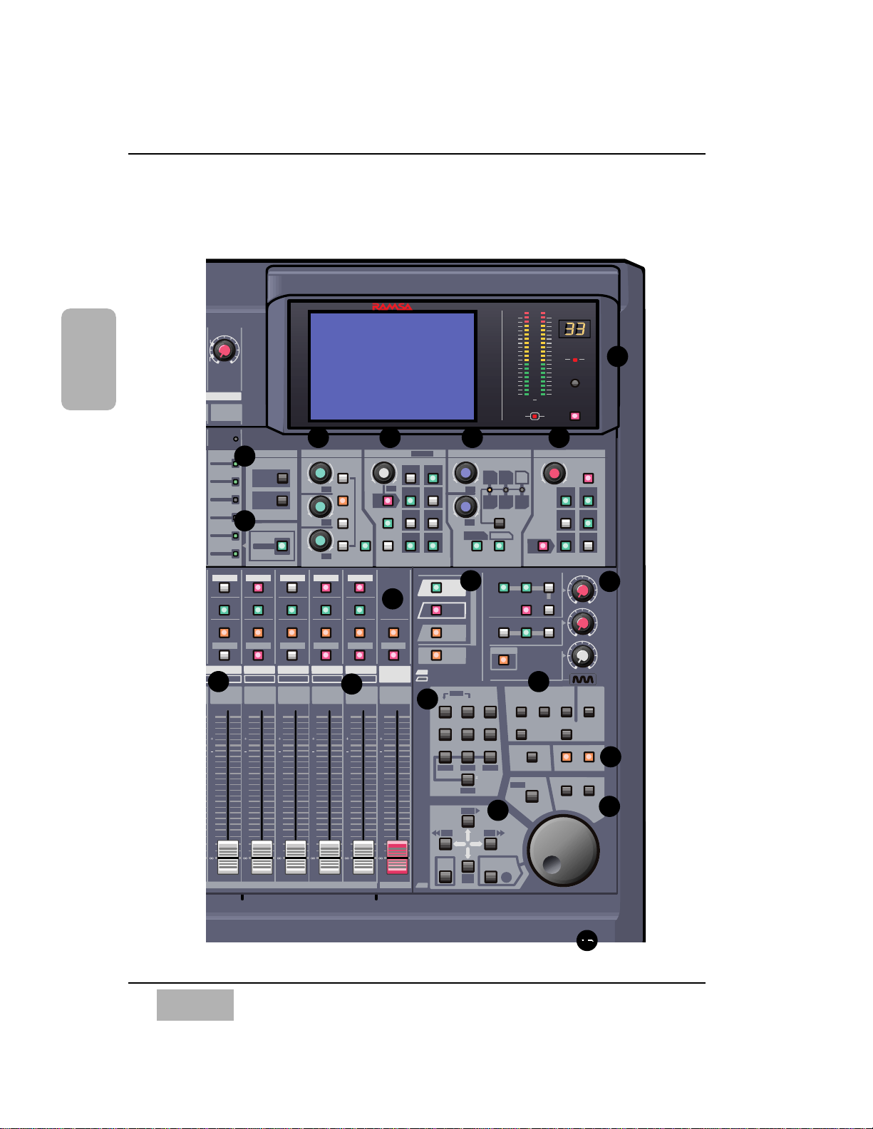
2-2 Top Panel
The illustrations on this page and the next depict the Top Panel of the DA7.
The number assignments are reflected on the Top Panel cutaway view on
page 2-4. Page 2-5, adjacent to the cutaway view, provides the explanation of
the numbered sections of the Top Panel.
Chapter 2
DA7 Users’ Guide
2-3
2
DA7 Tour
/CURSOR
1 2 3 4 5 6 7 8 9 10 11 12 13 14 15 16
BUS 2 BUS 4
BUS 6
BUS 8
25 26 27 28 29 30 31 3217 18 19 20 21 22 23 24
MONITOR A
MONITOR B
SOLO
MONITOR
2TR A
L/R
MONITOR A
L/R
2TR B
AUX
AUX
MONO
LEVEL
PRE
ON / OFF
FADER
CONTROL
12
56
3
4
BUS ASSIGN
PAN
12
7
4
3
6
8
DIRECT
L/R
ON
ON
5
PAN /ASSIGN /
AUX
DYNAMICS / DELAY
EQUALIZERMASTER DISPLAY
H
HM
LM
ON
L
EQ
Q
FREQ
GAIN
R
L
+-
+-
+-
+-
+-
+-
ON
ON
PARAMETER SELECT
DYNAMICS
DELAY
BUS 1 BUS 3 BUS 5 BUS 7
MASTER
L/R
12345678910111213141516
AUX
SND 1
AUX
SND 2
AUX
SND 3
AUX
SND 4
AUX
SND 5 BUS 1 BUS 2 BUS 3 BUS 4
AUX
SND 6
AUX
RTN 1
AUX
RTN 2
AUX
RTN 3
AUX
RTN 4
AUX
RTN 5
AUX
RTN 6 BUS 6 BUS 7 BUS 8BUS 5
MASTER L/R
RATIO
ATK
RLS
GAIN
DLY
THL
INPUT
1-16
INPUT
17-32
AUX
/ BUS
CUSTOM
/ MIDI
SURROUND
SUB
SL
L
C
R
SR
AUTOMATION
AUX
RED
GREEN
AUX 2
AUX 3
AUX 4
AUX 5
AUX 6
AUX 1
AUX 2
AUX 3
AUX 4
AUX 5
AUX 6
AUX 1
AUX 2
AUX 3
AUX 4
AUX 5
AUX 6
AUX 1
AUX 2
AUX 3
AUX 4
AUX 5
AUX 6
AUX 1
AUX 2
AUX 3
AUX 4
AUX 5
AUX 6
AUX 1
AUX 2
AUX 3
AUX 4
AUX 5
AUX 6
AUX 1
AUX 2
AUX 3
AUX 4
AUX 5
AUX 6
AUX 1
AUX 2
AUX 3
AUX 4
AUX 5
AUX 6
AUX 1
AUX 2
AUX 3
AUX 4
AUX 5
AUX 6
AUX 1
AUX 2
AUX 3
AUX 4
AUX 5
AUX 6
AUX 1
AUX 2
AUX 3
AUX 4
AUX 5
AUX 6
AUX 1
AUX 2
AUX 3
AUX 4
AUX 5
AUX 6
AUX 1
AUX 2
AUX 3
AUX 4
AUX 5
AUX 6
AUX 1
AUX 2
AUX 3
AUX 4
AUX 5
AUX 6
AUX 1
AUX 2
AUX 3
AUX 4
AUX 5
AUX 6
AUX 1
AUX 2
AUX 3
AUX 4
AUX 5
AUX 6
AUX 1
MMC
PLAY
REW
FF
STOP
REC
1
2
4
5
7
8
0
3
6
9
WRITE
UNDO/REDO
READ
STORE
RECALL
ABC DEF
JKLGHI MNO
TUV
PQRS WXYZ
UTILITY MIDI
D-I/O
GROUP
AUTOMATION
SOLO SOLO SOLO SOLO SOLO SOLO SOLO SOLO SOLO SOLO SOLO SOLO SOLO SOLO SOLO SOLO SOLO SOLO SOLO SOLO
FLIP FLIP FLIP FLIP FLIP FLIP FLIP FLIP FLIP FLIP FLIP FLIP FLIP FLIP FLIP FLIP FLIP FLIP FLIP FLIP
ON ON ON ON ON ON ON ON ON ON ON ON ON ON ON ON ON ON ON ON ON
SELECT SELECT SELECT SELECT SELECT SELECT SELECT SELECT SELECT SELECT SELECT SELECT SELECT SELECT SELECT SELECT SELECT SELECT SELECT SELECT SELECT
10
10
40
30
20
10
10
40
30
20
0
10
10
40
30
20
0
10
10
40
30
20
0
10
10
40
30
20
0
10
10
40
30
20
0
10
10
40
30
20
0
10
10
40
30
20
0
10
10
40
30
20
0
10
10
40
30
20
0
10
10
40
30
20
0
10
10
40
30
20
0
10
10
40
30
20
0
10
10
40
30
20
0
10
10
40
30
20
0
10
10
40
30
20
0
10
10
40
30
20
0
10
10
40
30
20
0
10
10
40
30
20
0
10
10
40
30
20
0
10
10
40
30
20
INPUT INPUT INPUT INPUT INPUT INPUT INPUT INPUT INPUT INPUT INPUT INPUT INPUT INPUT INPUT INPUT
MIC/LINEMIC/LINEMIC/LINEMIC/LINEMIC/LINEMIC/LINEMIC/LINEMIC/LINEMIC/LINEMIC/LINEMIC/LINEMIC/LINEMIC/LINEMIC/LINEMIC/LINEMIC/LINE
PEAK /
SIGNAL
PEAK /
SIGNAL
PEAK /
SIGNAL
PEAK /
SIGNAL
PEAK /
SIGNAL
PEAK /
SIGNAL
PEAK /
SIGNAL
PEAK /
SIGNAL
PEAK /
SIGNAL
PEAK /
SIGNAL
PEAK /
SIGNAL
PEAK /
SIGNAL
PEAK /
SIGNAL
PEAK /
SIGNAL
PEAK /
SIGNAL
PEAK /
SIGNAL
+10
-60
+10
-60
+10
-60
+10
-60
+10
-60
+10
-60
+10
-60
+10
-60
+10
-60
+10
-60
+10
-60
+10
-60
+10
-60
+10
-60
+10
-60
+10
-60
010
010
010
T. B.
LEVEL
LIBRARY
SET UP
SHIFT
LOCATE
SET
REPLAY
LOOP
LOOP
SCENE MEMORY
PARAMETER
MONITOR
B LEVEL
MONITOR
A LEVEL
MIC
METER
CHANNEL
SLOT 1
SLOT 3
SLOT 2
Digital Mixer
WR - DA7
L
R
50
35
25
OL
20
15
10
8
6
4
2
MEMORY
MULTI-
CH VIEW
CONTRAST
CONSOLE
LOCK
SOLO
CURSOR
MODE
TALK BACK
FADER
CH
EQ
PAN/SURR
LIBRARY
SEL/MAN
FADER
CH
EQ
PAN/SURR
LIBRARY
SEL/MAN
FADER
CH
EQ
PAN/SURR
LIBRARY
SEL/MAN
FADER
CH
EQ
PAN/SURR
LIBRARY
SEL/MAN
FADER
CH
EQ
PAN/SURR
LIBRARY
SEL/MAN
FADER
CH
EQ
PAN/SURR
LIBRARY
SEL/MAN
FADER
CH
EQ
PAN/SURR
LIBRARY
SEL/MAN
FADER
CH
EQ
PAN/SURR
LIBRARY
SEL/MAN
FADER
CH
EQ
PAN/SURR
LIBRARY
SEL/MAN
FADER
CH
EQ
PAN/SURR
LIBRARY
SEL/MAN
FADER
CH
EQ
PAN/SURR
LIBRARY
SEL/MAN
FADER
CH
EQ
PAN/SURR
LIBRARY
SEL/MAN
FADER
CH
EQ
PAN/SURR
LIBRARY
SEL/MAN
FADER
CH
EQ
PAN/SURR
LIBRARY
SEL/MAN
FADER
CH
EQ
PAN/SURR
LIBRARY
SEL/MAN
FADER
CH
EQ
PAN/SURR
LIBRARY
SEL/MAN
ENTER
ON
-10+4-10+4-10+4-10+4-10+4-10+4-10+4-10+4-10+4-10+4-10+4-10+4-10+4-10+4-10+4-10
+4
DA7 Top Panel
Page 25
Illustrated Guide
Explanations of the numbered sections begins on the next page.
Chapter 2
DA7 Users’ Guide
2-4
2
DA7 Tour
/CURSOR
15 16
BUS 2 BUS 4
BUS 6
BUS 8
31 32
MONITOR A
MONITOR B
SOLO
MONITOR
2TR A
L/R
MONITOR A
L/R
2TR B
AUX
AUX
MONO
LEVEL
PRE
ON / OFF
FADER
CONTROL
12
56
3
4
BUS ASSIGN
PAN
12
7
4
3
6
8
DIRECT
L/R
ON
ON
5
PAN /ASSIGN /
AUX
DYNAMICS / DELAY
EQUALIZERMASTER DISPLAY
H
HM
LM
ON
L
EQ
Q
FREQ
GAIN
R
L
+-
+-
+-
+-
+-
+-
ON
ON
PARAMETER SELECT
DYNAMICS
DELAY
BUS 1 BUS 3 BUS 5 BUS 7
MASTER
L/R
15 16
BUS 3 BUS 4 BUS 6 BUS 7 BUS 8BUS 5
MASTER L/R
RATIO
ATK
RLS
GAIN
DLY
THL
INPUT
1-16
INPUT
17-32
AUX
/ BUS
CUSTOM
/ MIDI
SURROUND
SUB
SL
L
C
R
SR
AUTOMATION
AUX
RED
GREEN
AUX 2
AUX 3
AUX 4
AUX 5
AUX 6
AUX 1
AUX 2
AUX 3
AUX 4
AUX 5
AUX 6
AUX 1
MMC
PLAY
REW
FF
STOP
REC
1
2
4
5
7
8
0
3
6
9
WRITE
UNDO/REDO
READ
STORE
RECALL
ABC DEF
JKLGHI MNO
TUV
PQRS WXYZ
UTILITY MIDI
D-I/O
GROUP
AUTOMATION
SOLO SOLO SOLO SOLO SOLO SOLO
FLIP FLIP FLIP FLIP FLIP FLIP
ON ON ON ON ON ON ON
SELECT SELECT SELECT SELECT SELECT SELECT SELECT
0
10
10
40
30
20
0
10
10
40
30
20
0
10
10
40
30
20
0
10
10
40
30
20
0
10
10
40
30
20
0
10
10
40
30
20
0
10
10
40
30
20
INPUT INPUT
MIC/LINEMIC/LINE
PEAK /
SIGNAL
PEAK /
SIGNAL
+10
-60
+10
-60
010
010
010
T. B.
LEVEL
LIBRARY
SET UP
SHIFT
LOCATE
SET
REPLAY
LOOP
LOOP
SCENE MEMORY
PARAMETER
MONITOR
B LEVEL
MONITOR
A LEVEL
MIC
METER
CHANNEL
Digital Mixer
WR - DA7
L
R
50
35
25
OL
20
15
10
8
6
4
2
MEMORY
MULTI-
CH VIEW
CONTRAST
CONSOLE
LOCK
SOLO
CURSOR
MODE
TALK BACK
FADER
CH
EQ
PAN/SURR
LIBRARY
SEL/MAN
FADER
CH
EQ
PAN/SURR
LIBRARY
SEL/MAN
ENTER
ON
-10
+4
-10
+4
DA7 Top Panel
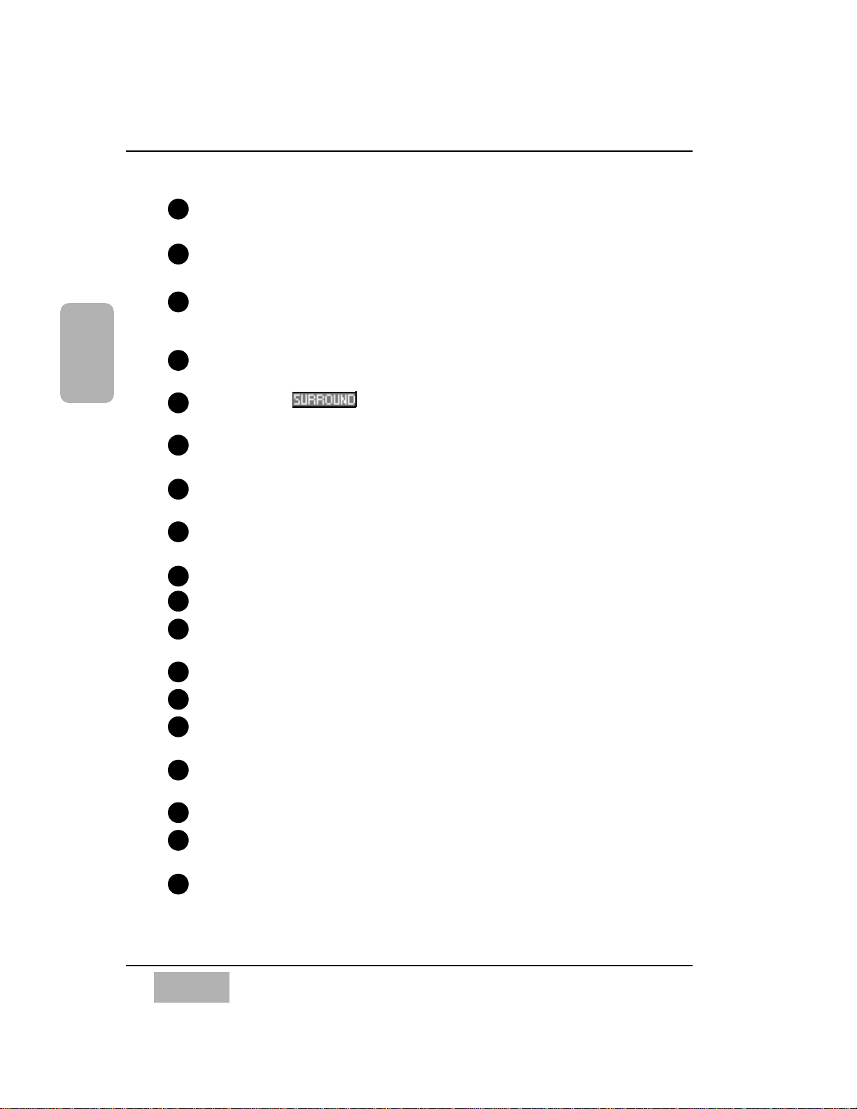
1
2
3
4 5 6
8
9
10
11
7
12
13
14
15
17
16
18
Page 26
Chapter 2
DA7 Users’ Guide
2-5
2
DA7 Tour
Channel Strip – input gain controls with channel control and status
indicators. Also called a Channel Fader Strip.
AUTOMATION/AUX LED button – selects the display mode of the
Channel Strip LED field indicators, and arms the AUTOMATION system.
MASTER DISPLAY section – the METER and CHANNEL buttons are
direct buttons to the respective LCD screen windows. These should be
considered "home base" for the LCD display.
EQUALIZER section – controls for setting the equalization parameters
for a selected channel.
PAN/ASSIGN/ , BUS ASSIGN section – controls for setting
the pan and bus assignments for a selected channel.
DYNAMICS/DELAY section – controls for setting the onboard dynamics
processing parameters for a selected channel.
AUX section – controls for routing channels to outboard sources and for
defining the signal path as either pre-fader or post-fader.
Display Bridge – contains the LCD screen, L/R meter display, and
primary mixer display status indicators.
BUS Fader Strip – controls for output BUSes.
MASTER L/R Fader Strip – controls for L/R MASTER output.
Fader Layer Controls section – selects the current fader layer to be
displayed.
MONITOR section – volume and selection controls for monitoring.
SETUP section – mixer function, or display control buttons.
SCENE MEMORY section – buttons for writing and reading the 50 mixer
scene memories.
LIBRARY section – buttons for storing and recalling Channel, EQ and
Dynamics libraries.
Keypad – alphanumeric keys for entering numbers or text.
Cursor Control section – buttons and controls for defining the cursor
actions.
Headset Control section – the location of the headset connector and
the level control of the DA7 is immediately below the right front edge of
the Top Panel.
10
11
12
13
14
15
16
17
18
1
2
3
4
5
6
7
8
9
Page 27
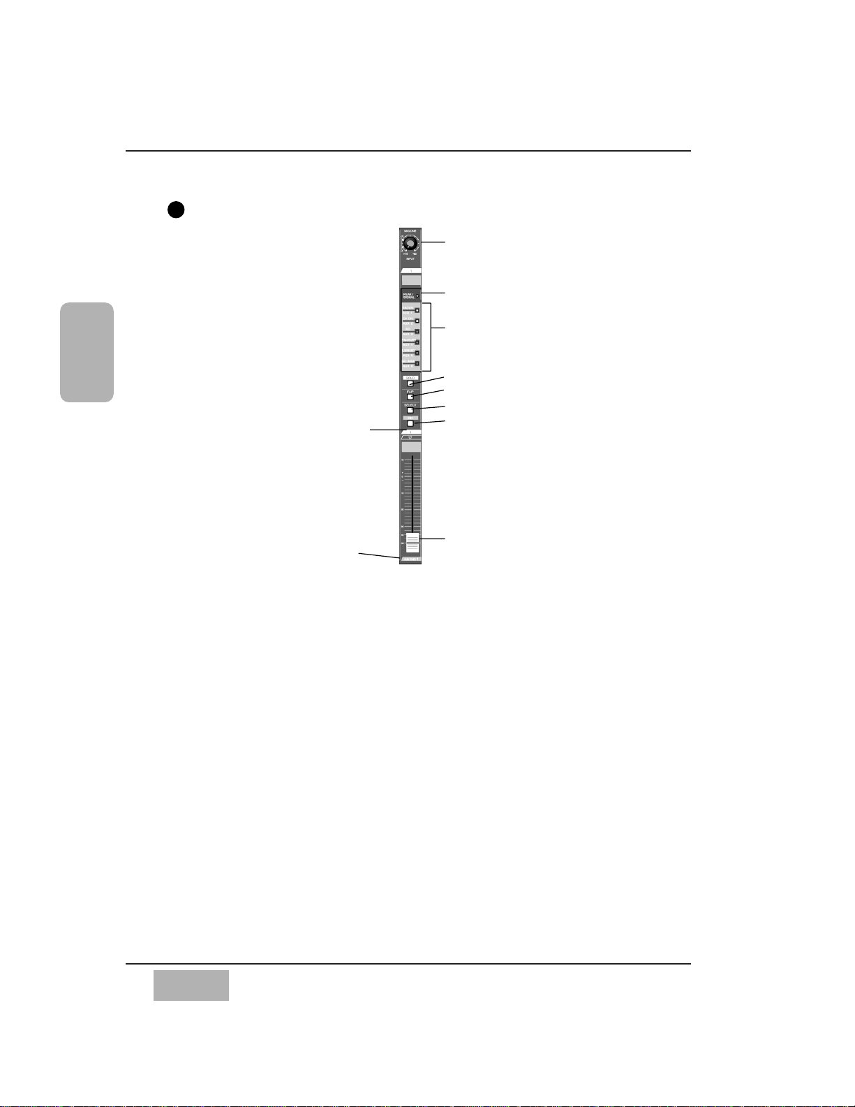
Channel Fader Strip
There are sixteen Channel Fader Strips on the DA7. The functionality of each
Channel Fader Strip is determined by which of the four Fader Layer
controls selected: INPUT 1-16, INPUT 17-32, AUX/BUS, and a user
CUSTOM/MIDI function.
The MIC/LINE INPUT knob varies the channel input gain volume and adjusts
for either a mic or line-level input. Due to the high quality design of this
circuit, there is no pad switch necessary; the input knob range sets the input
level. This knob only affects the analog inputs 1-16.
The PEAK/SIGNAL LED indicates when an input signal is present (green),
and when the input signal level is too high (red).
The LED field indicators reflect the auxiliary (AUX) routing assignments and
automation parameters. The LED color signifies the AUTOMATION/AUX
button selection, AUX (green), or AUTOMATION (red).
The SOLO LED button toggles on (red) or off. When on, the channel output
will be routed to the MONITOR A speakers (overriding the MONITOR A
input), and to the headphones.
The FLIP LED button flips the control of the Channel Fader Strip from one
input layer to the other. The LED color indicates the current input selection
and matches the Fader Layer control LED button colors, INPUTS 1-16
(green) or INPUTS 17-32 (red).
Chapter 2
DA7 Users’ Guide
2-6
2
DA7 Tour
Fader
MIC/LINE INPUT knob
PEAK/SIGNAL LED
LED field indicators for AUX 1-6, and
automation parameters, CH, EQ,
PANASSIGN/SURR, LIBRARY and SEL/MAN
SOLO LED button
FLIP LED button
SELECT LED button
On LED button
Channel Fader Strip
Channel numbers
AUX/BUS Layer
function
1
Page 28
The SELECT LED button, when on (orange), identifies the channel as the
current channel selected. Only one Fader Strip can be selected at a time
(unless it’s in stereo or link mode).
For more detail, see Chapter 5, Channel, Library, and Meter Windows.
The ON LED button toggles on (red) and off. When on, the channel output is
active.
There are two channel numbers for each strip, indicating the INPUT
connections on the Rear Panel of the DA7.
The AUX/BUS label at the bottom of a Channel Fader Strip indicates its
function when the AUX/BUS Fader Layer control is selected.
See Chapter 6, Fader Layers and Channel Strips for additional information.
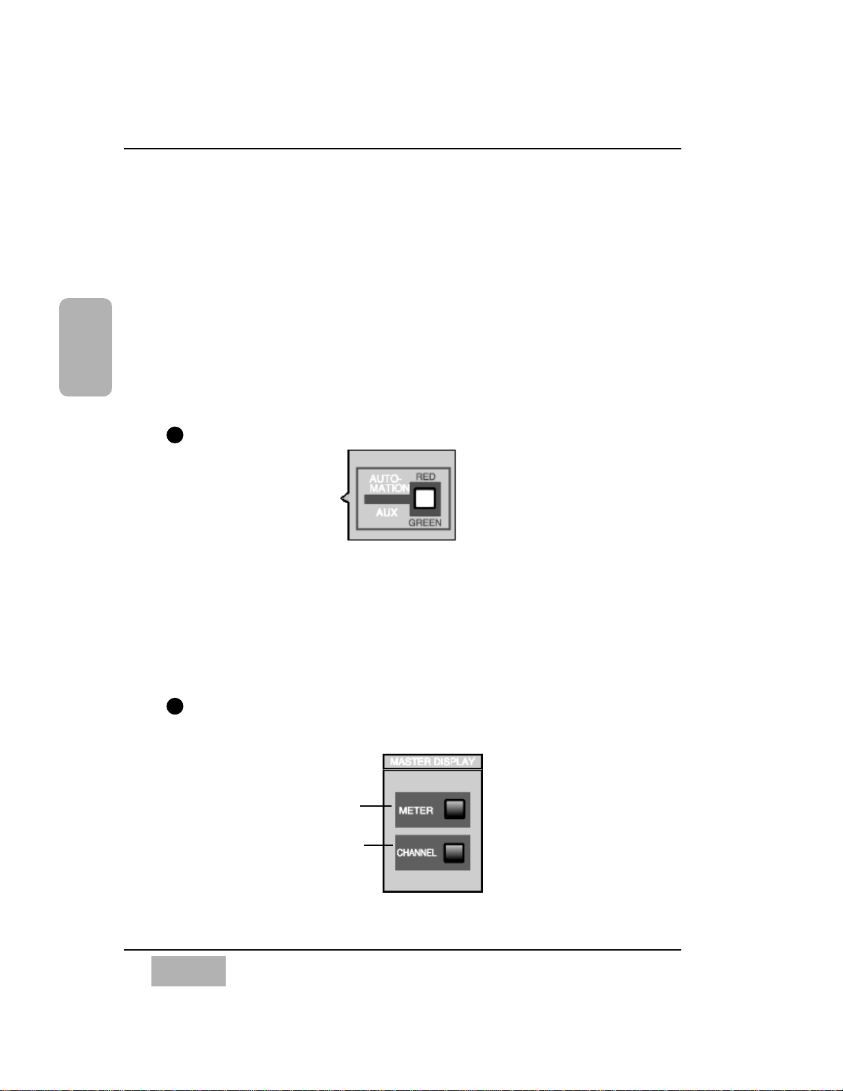
AUTOMATION/AUX LED Button
The AUTOMATION/AUX LED button toggles the display of the Channel
Fader Strips LED field indicators. The LED color indicates the current
selection.
See Chapter 14, Automation and Chapter 10, AUX for additional
information.
MASTER DISPLAY Section
Chapter 2
DA7 Users’ Guide
2-7
2
DA7 Tour
METER
button
CHANNEL
button
2
3
AUTOMATION/AUX LED Button
MASTER DISPLAY Section
Page 29
Pressing the METER button will display the [METER] window group on the
LCD screen in the Display Bridge. Pressing the METER button again will
cycle the three window selections: [METER INPUTS 1-32], [BUS/AUX],
[SLOT].
Pressing the CHANNEL button will display the [CHANNEL] window group
on the LCD screen in the Display Bridge. The window displayed will show
the current mixer strip selected.
See Chapter 5, Channel, Library, and Meter Windows for additional
information.
EQUALIZER Section
There are three parameter knobs and four frequency range LED buttons in
the EQUALIZER section, which are used to change the EQ settings of the
currently selected channel. The EQ ON LED button toggles the EQUALIZER
on (green) and off. When the controls are active, adjustments can be made to
the currently selected channel.
The three knobs are labeled Q (quality), FREQ (frequency), and GAIN
(gain). The additional labeling of (left), (surround left), and
(surround subwoofer) indicate the surround sound parameters that are
controlled by the knobs when the [SURROUND] mixing area is activated.
Surround sound capabilities are discussed in Chapter 8.
The four frequency band LED buttons can be selected one at a time, and turn
on (orange) to show which band is operating. They are labeled H (high), HM
(high-mid), LM (low-mid), and L (low).
Pressing the GAIN knob displays the [EQUALIZER] window on the LCD
screen. Once the [EQUALIZER] is displayed in the LCD window, these
buttons perform other shortcut functions.
The EQUALIZER section is detailed in Chapter 7.
SUB
SL
L
Chapter 2
DA7 Users’ Guide
2-8
2
DA7 Tour
EQUALIZER
H
HM
LM
ON
L
EQ
Q
FREQ
GAIN
+-
+-
+-
SUB
SL
L
4
EQUALIZER Section
Q (quality) parameter knob or
left surround sound
attenuator
FREQ (frequency) parameter
knob or surround left
surround sound attenuator
GAIN parameter knob or
subwoofer surround sound
attenuator
Frequency band LED
buttons
EQ ON LED button
Page 30
Chapter 2
DA7 Users’ Guide
2-9
2
DA7 Tour
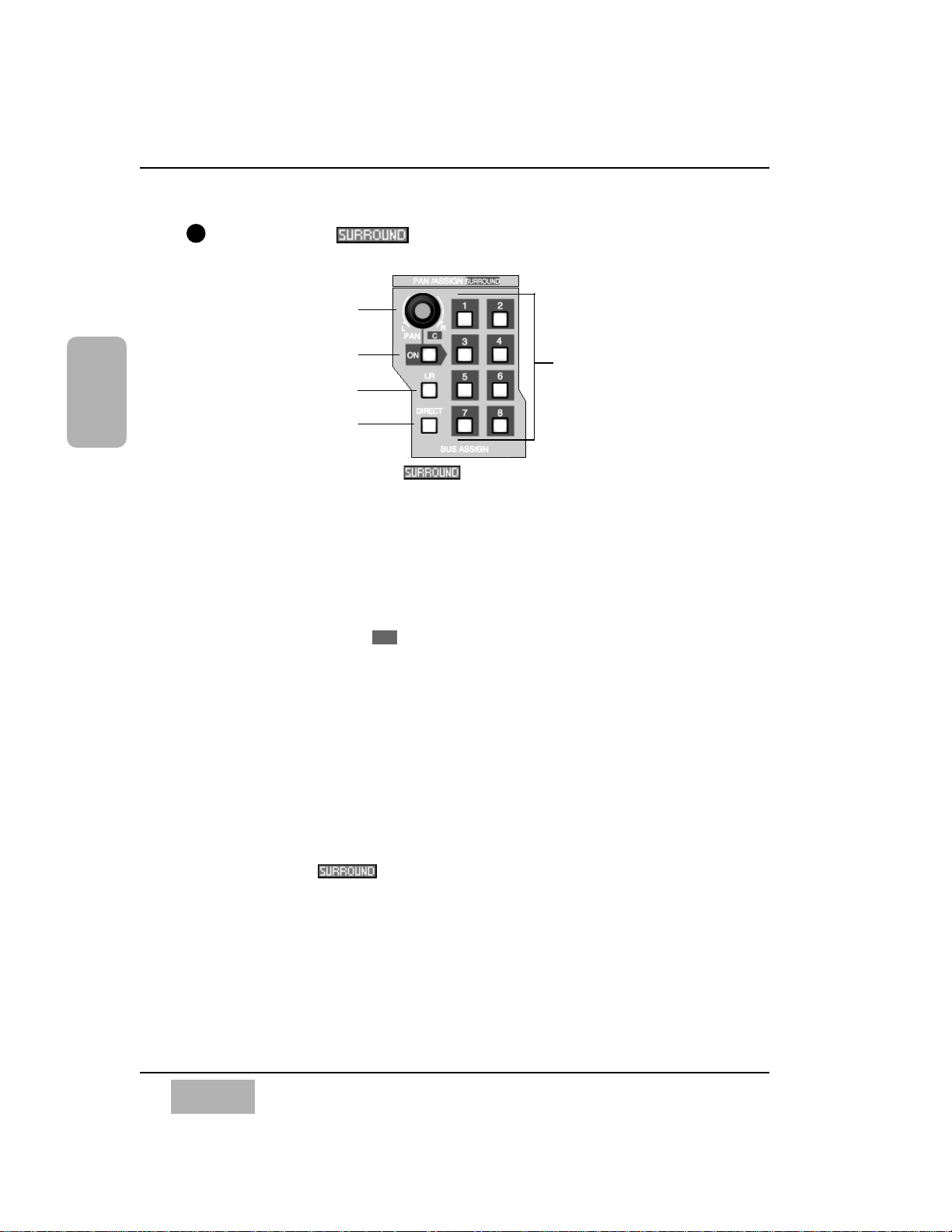
PAN/ASSIGN/ , BUS ASSIGN Section
Pan, bus assignment, and surround sound parameters for the selected
channel is set within this area. The pan control is always active for the L/R
bus, so you do not need to activate the ON button to pan across the Master
L/R out. However, if you wish to pan between odd/even buses, you must
push the ON button. Assignment to the DIRECT output is not affected by the
pan control.
The additional labeling of (center) indicates the surround sound
parameter that is controlled by the knob when the [SURROUND] mixing
area is activated.
The L/R, the DIRECT, and the BUS ASSIGN LED buttons toggle on (green)
and off. In addition to the eight bus selections, labeled 1 - 8, selections for
L/R (master L/R) output and DIRECT output are available. The DIRECT
output works in conjunction with the option cards installed in the DA7 Rear
Panel, routing signals directly to the cards.
The DIRECT output is detailed in Chapter 12, D-I/O.
Pressing the PAN knob displays the [SURROUND] window on the LCD
screen.
The PAN/ASSIGN , BUS ASSIGN section of the Top Panel is
detailed in Chapter 8.
C
5
PAN/ASSIGN/ , BUS ASSIGN Section
PAN parameter knob or
center surround sound
attenuator
PAN ON LED button
MASTER L/R LED button
DIRECT LED button
BUS ASSIGN LED
buttons
Page 31

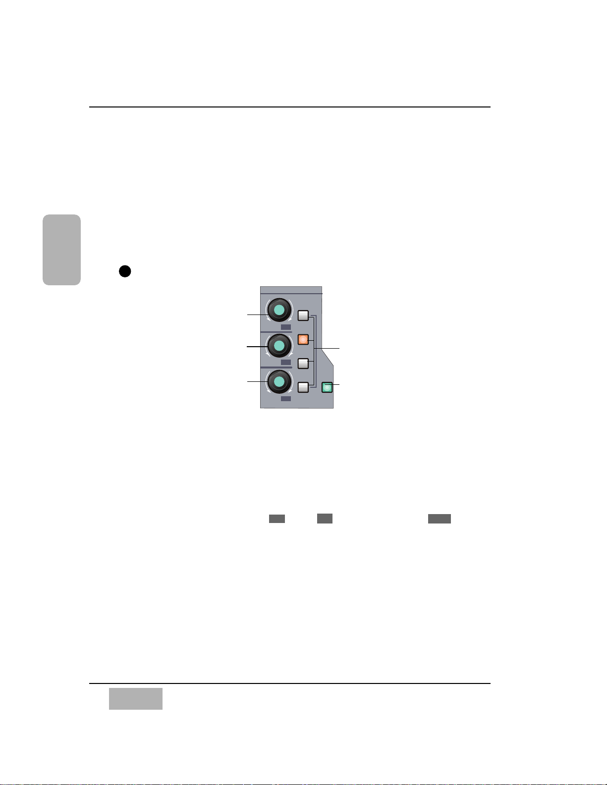
DYNAMICS/DELAY Section
DYNAMICS and/or DELAY processing can be added to each of the DA7
Channels. Pressing the PARAMETER SELECT button cycles the current
parameter selections, which are grouped in pairs. The top knob adjusts the
top parameter selection in the pair, and the bottom knob adjusts the bottom
parameter selection in the pair. The DYNAMICS ON LED button toggles the
dynamics processing on (green) and off for the selected channel, and the
DELAY ON LED button toggles the delay on (green) and off.
The additional labeling of (right) and (surround right) indicates the
surround sound parameters that are controlled by the knobs when the
[SURROUND SOUND] mixing area is activated. The surround sound
function is activated in the [SURROUND] window of the [SURROUND]
window group.
See Chapter 8 for more information on surround sound.
Pressing the bottom knob displays the [DYNAMICS] window group on the
LCD screen.
For more information on the DYNAMICS/DELAY section of the Top Panel,
see Chapter 9.
SR
R
Chapter 2
DA7 Users’ Guide
2-10
2
DA7 Tour
6
DYNAMICS/DELAY Section
THL (threshold),
ATK(attack), DLY (delay)
parameter knob or right
surround sound attenuator
RATIO, RLS (release),
GAIN parameter knob or
surround right surround
sound attenuator
DYNAMICS ON LED button
PARAMETER
SELECT LEDs
PARAMETER
SELECT button
DELAY ON LED
button
Page 32

Chapter 2
DA7 Users’ Guide
2-11
2
DA7 Tour
AUX Section
This section of the Top Panel contains controls for routing selected channels
from/to outboard sources. These six aux routes are independent of the
channel input connectors on the Rear Panel of the DA7 and greatly expand
the flexibility of the mixer. They can be used as six mono sends, or in stereo
pairs (such as 1&2, 3&4, 5&6), and six mono returns, or stereo pairs. There
are two digital aux routes, AUX 1/2, and four analog aux routes, AUX 3/4
and AUX 5/6. AUX 3/4 and AUX 5/6 are paired for convenience on the Rear
Panel connectors. If you wish to use them as Mono channels, connect a
standard audio “Y” cable (available at your dealer) to split the audio
channels.
With a channel selected, press an AUX 1-6 LED button (green) to select
which aux route you wish to assign for the channel. The LEVEL knob
performs two functions. By pressing the knob, you will assign the channel to
the selected aux route, and by turning the knob, you can adjust the
individual channel output to the aux selection. The LED field of the Channel
Fader Strips will reflect the aux assignments for the channels.
Aux routing is defaulted to a post-fader condition for the selected channel.
Press the PRE LED button to select it (red) and change the aux routing
function to a pre-fader condition.
Press the FADER CONTROL LED button to select it (red) and display the
[FADER CONTROL] window group on the LCD screen. The window
displayed will be determined by the current AUX 1-6 LED button selection.
The channel fader status of the 32 input channels for the aux selected will be
reflected in the [FADER CONTROL] window, and the Channel Faders will
reset to their respective level positions for the aux selected.
The AUX/BUS designations at the bottom of the Channel Fader Strips
identify the strip functions when the Fader Layer AUX/BUS LED button is
pressed.
For more information on the AUX section of the Top Panel see Chapter 10.
7
AUX Section
Send LEVEL volume
and assign ON/OFF
knob
FADER CONTROL
mode LED button
PRE LED button
AUX 1-6 select LED
buttons
Page 33

Display Bridge
The Display Bridge contains the information for the current status of the
DA7 and the LCD screen. The various windows for the functions and features
of the mixer are displayed on the LCD screen.
BUS Fader Strip
There are four BUS Fader Strips on the DA7. In conjunction with the
Fader Layer controls, each strip directly controls the BUS outputs, or the
AUX/BUS functions which are indicated on the bottom of the strip, or a user
CUSTOM/MIDI function.
Chapter 2
DA7 Users’ Guide
2-12
2
DA7 Tour
Fader
AUX/BUS Layer function
SOLO LED button
FLIP LED button
SELECT LED button
ON LED button
Bus Assign
numbers
8
9
BUS Fader Strip
LCD screen
L/R Meter display
MEMORY
numeric readout
CONSOLE LOCK
LED status
indicator
LCD CONTRAST
control knob
MULTI-CH VIEW
LED button
SOLO LED status
indicator
Display Bridge Section
Page 34

Chapter 2
DA7 Users’ Guide
2-13
2
DA7 Tour
The SOLO LED button toggles on (red) or off. When on, the selected bus
output will be routed to the MONITOR A speakers and headphones,
overriding the previous input.
There are two bus numbers for each strip, indicating the BUS ASSIGN
selections that can be controlled by the strip.
The FLIP LED button flips the BUS Fader Strip from controlling one bus to
controlling the other bus for the strip. The LED color (red or green) indicates
the current bus selection.
The SELECT LED button, when on (orange), identifies the bus strip as the
current bus strip selected. Only one BUS Fader Strip can be selected at a
time unless they are paired for LINK or STEREO operation.
The ON LED button toggles on (red) and off. When on, the bus output is
active.
The AUX/BUS indication at the bottom of the BUS Fader Strip indicates the
strip function when the AUX/BUS Fader Layer control is selected.
See Chapter 6, Fader Layers and Channel Strips for additional information.
MASTER L/R Fader Strip
The MASTER L/R Fader Strip controls the DA7 master L/R output.
The SELECT LED button, when on (orange), identifies the strip as the
current fader strip selection.
The ON LED button toggles on (red) and off. When on, the master output is
active.
See Chapter 6, Fader Layers and Channel Strips for additional
information.
Fader
AUX/BUS Layer function
SELECT LED button
ON LED button
10
MASTER L/R Fader Strip
Page 35

Fader Layer Controls Section
The Fader Layer controls significantly expand the flexibility of the DA7
mixer. The LED button selections define the current function for the fader
strips.
LED buttons for the Fader Layer controls assist you in determining or
checking the current channel and bus fader settings on the mixer.
INPUT 1-16, when selected (green), resets the fader strips to control channel
inputs 1 through 16, and buses 1, 3, 5, and 7. When selected, the faders
move to the positions reflecting the current settings for the layer, unless
previously flipped. To reset a flipped Channel Fader Strip, press the FLIP
button. To reset all the currently flipped Channel Fader Strips, press the
INPUT 1-16 Fader Layer control button and hold it for two seconds. This
will set all faders to the selected layer.
INPUT 17-32, when selected (red), resets the fader strips to control channel
inputs 17 through 32, and buses 2, 4, 6, and 8. When selected, the faders
move to the positions reflecting the current settings for the layer, unless
previously flipped. To reset a flipped Channel Fader Strip, press the FLIP
button. To reset all the currently flipped Channel Fader Strips, press the
INPUT 17-32 Fader Layer control button and hold it for two seconds. This
will set all faders to the selected layer.
AUX/BUS, when selected (orange), resets the fader strips to control the aux
sends, aux returns, and bus outputs, while the faders move to the positions
reflecting the current fader settings for the layer.
CUSTOM/MIDI is a user-definable Fader Layer control, where the functions
are selectable.
See Chapter 11, MIDI for more information on the DA7 MIDI feature, and
Chapter 6, Fader Layers and Channel Strips for additional information.
Chapter 2
DA7 Users’ Guide
2-14
2
DA7 Tour
INPUT 1-16 LED button
(green)
INPUT 17-32 LED button
(red)
AUX/BUS LED button
(orange)
CUSTOM/MIDI LED button
(orange)
11
Fader Layer Controls Section
Page 36

MONITOR Section
The DA7 provides controls for two monitor outputs and a talkback circuit.
There are source selection LED buttons for the MONITOR A and MONITOR
B outputs, and LEVEL knobs for both of the monitor outputs and the
talkback circuit.
MONITOR A Controls
The MONITOR A selection LED buttons route the input selected (green) to
the MONITOR A OUTPUT (CR) (Control Room) connections on the Rear
Panel of the mixer and to the headphones. The selections are:
L/R routes the MASTER L/R output to the monitors.
2TR A routes the device that is connected to 2TR A IN on the Rear
Panel to the monitors.
2TR B routes the device that is connected to 2TR B IN on the Rear
Panel to the monitors.
AUX routes the AUX SEND outputs to the monitors. Press the AUX
LED button to monitor the selections, beginning with AUX SEND 1/2,
followed by AUX SEND 3/4, and AUX SEND 5/6. The MEMORY
numeric readout on the Display Bridge will momentarily display the
AUX SEND selections.
The MONO button, when on (red), sums the selected input and sends a
monaural signal to the monitors. This will not affect the 2TR B output
stereo signal.
Chapter 2
DA7 Users’ Guide
2-15
2
DA7 Tour
12
●
●
●
●
MONITOR Section
MONITOR A source
selection buttons
MONITOR B source
selection buttons
Talkback ON LED
button
LEVEL knobs
2TR A
L/R
MONITOR A
MONITOR A
MONITOR B
ON
TALK BACK
MONO
2TR B
AUX
AUX
L/R
MONITOR
010
A LEVEL
MONITOR
010
B LEVEL
T. B.
LEVEL
010
MIC
Page 37

MONITOR B Controls
The MONITOR B selection LED buttons route the input selected (green) to
the MONITOR B OUTPUT (STUDIO) connections on the Rear Panel of the
mixer. The selections are:
MONITOR A routes the current MONITOR A selection to the studio
monitors.
AUX routes the AUX SEND outputs to the monitors. Press the AUX LED
button to monitor the selections beginning with AUX SEND 1/2,
followed by AUX SEND 3/4, and AUX SEND 5/6. The MEMORY
numeric readout on the Display Bridge will momentarily display the
AUX SEND selections.
TALKBACK
The TALKBACK ON button controls the talkback microphone installed in
the Top Panel of the DA7. When on (orange), the MIC is active and the
MONITOR A speakers will be dimmed. This can be either a “push-to-talk”
momentary interrupt type button, or a “push on/push off” type button. This
is selected in the [UTILITY] window. Talkback routing is selected in the
[SOLO MONITOR] window. There is also a phone jack on the Rear Panel
that allows for remote Talk back operation.
For additional information on the talkback, see Chapter 16, Utility and
Solo monitor.
SETUP Section
These are direct-action buttons that will display the selected windows in the
LCD screen of the
Display Bridge
. In addition, pressing one of these
buttons then one of
the 10
KeyPad
buttons, lets you directly recall the
selected window of the window group. See page Appendix B-3, LCD Screen
Displays for more information.
Chapter 2
DA7 Users’ Guide
2-16
2
DA7 Tour
SOLO
MONITOR
UTILITY MIDI
D-I/O
GROUP
AUTOMATION
SET UP
●
●
13
SETUP Section
MIDI button
UTILITY button
GROUP button
D-I/O button
SOLO MONITOR
button
AUTOMATION
button
Page 38

Chapter 2
DA7 Users’ Guide
2-17
2
DA7 Tour
UTILITY Button
Pressing the UTILITY button will display the [UTILITY] window group on
the LCD screen in the Display Bridge. The window displayed will be
determined by the window selection buttons at the bottom of the window.
Pressing the UTILITY button again will cycle the window selections:
[OSC_BATT], [CONFIGuration], [USER CuSToM].
See Chapter 16, Utility and Solo Monitor for additional information.
MIDI Button
Pressing the MIDI button will display the [MIDI] window group on the LCD
screen in the Display Bridge. Pressing the MIDI button again will cycle the
window selections: [SETUP], [PRoGram ASsiGN], [ConTRoL ASsiGN],
[BULK], [REMOTE].
See Chapter 11, MIDI for additional information.
D-I/O Button
Pressing the D-I/O button will display the [D-I/O] (Digital Input/Output)
window group on the LCD screen in the Display Bridge. Pressing the D-I/O
button again will cycle the window selections: [INPUT SET], [TO SLOT],
[DITHER].
See Chapter 12, D-I/O for additional information.
GROUP Button
Pressing the GROUP button will display the [GROUP] window selections on
the LCD screen in the Display Bridge. Pressing the GROUP button again
will cycle the window selections: [FADER GRouP], [MUTE GRouP],
[LINK/STR].
See Chapter 13, Group for additional information.
AUTOMATION Button
Pressing the AUTOMATION button will display the [AUTOMATION] window
group on the LCD screen in the Display Bridge. Pressing the AUTOMATION
button again will cycle the window selections: [SETUP], [EXECUTE],
[EVenT EDIT] .
See Chapter 14, Automation for more information.
SOLO MONITOR Button
This button displays Solo Monitor mode, Talk back assignment, and
Surround Monitor.
See Chapter 16, Utility and Solo Monitor for additional information.
Page 39

SCENE MEMORY Section
SCENE MEMORY allows you to store and recall complete mixer setups and
functions. There are fifty registers, numbered 01 through 50, available for
storage of mixer settings. Memory 00 is reserved for Automation.
Press either the WRITE LED button or the READ LED button (orange) to
select it and display the [ReaD/WriTe] window of the [SCENE MEMORY]
window group on the LCD screen of the Display Bridge.
There are two windows in the group; [RD/WT], and [XFADE]. The [RD/WT]
window is always the initial window displayed when either button is
selected. To change to the [XFADE] window, use the ARROW buttons to
navigate to the respective window selection button, and then press the
ENTER button, or press either the WRITE or READ LED buttons a second
time.
When the [RD/WT] window is displayed, the JogDial will scroll the [SCENE
MEMORY] list area of the window. This allows you to quickly access a
previously stored scene, locate an empty scene memory, or locate a scene
memory to be overwritten. By pressing the ENTER button after a scene has
been located, the mixer will immediately assume the setting for the stored
scene.
The MEMORY readout display will flash the memory number that is selected
until it is recalled. The selected memory will be displayed without flashing
once it has been recalled.
While the [RD/WT] window is displayed, pressing the ENTER button will
immediately overwrite the current scene memory with the settings that are
on the mixer at the moment the ENTER button is pressed, unless the
register is write-protected. See Chapter 15, Scene Memory for additional
information.
LIBRARY Section
Chapter 2
DA7 Users’ Guide
2-18
2
DA7 Tour
14
15
SCENE MEMORY Section
LIBRARY Section
WRITE LED
button
READ LED
button
STORE LED
button
RECALL LED
button
Page 40

Chapter 2
DA7 Users’ Guide
2-19
2
DA7 Tour
There are three mixer functions with associated libraries: CHANNEL,
EQUALIZER, DYNAMICS/DELAY. The library feature allows you to store
and recall individual function parameters to a separate library. There are fifty
registers for each library, numbered 01 through 50.
The RECALL button opens the library window for the selected function.
This means that if the [CHANNEL] window was displayed when you pressed
the RECALL button, the CHANNEL library will be displayed. The same goes
for the EQUALIZER AND DYNAMICS/DELAY libraries. Once selected, the
parameter knob will allow you to scroll through the stored memories. After
you have chosen a memory, press the RECALL button again and the selected
memory will be recalled to the currently selected function. You will also
automatically return to the main screen for the selected function.
While the library is displayed, pressing the STORE button will immediately
store the current function settings to the current memory location, unless the
memory location is write-protected.
See Chapter 5, Library for additional information.
Details on the Keypad, UNDO/REDO button, MMC/CURSOR button,
ARROW buttons, ENTER button, CURSOR MODE button, and JogDial
elements of the DA7 Top Panel are provided in Chapter 4 of the manual.
Headset Control Section
A stereo headset connector and the headset volume control are located
under the right front edge of the Top Panel of the DA7. The current
MONITOR A selection is always routed to the headset connector.
16
17
1
2
4
5
7
8
0
3
6
9
ABC DEF
JKLGHI MNO
TUV
PQRS WXYZ
SHIFT
LOCATE
SET
REPLAY
LOOP
LOOP
18
Keypad Cursor Control Section
Keypad and Cursor Control Section
ARROW buttons
ENTER button
CURSOR
MODE button
JogDial
UNDO/REDO button
MMC/CURSOR button
Page 41

2-3 Display Bridge
The Display Bridge for the DA7 is your “window” to the mixer functions
and features. There are seven elements comprising the Display Bridge: the
LCD screen, the L/R meter display, the MEMORY numeric readout, the
CONSOLE LOCK LED status indicator, the CONTRAST control knob, the
MULTI-CH VIEW (multi-channel) LED button, the SOLO LED status
indicator.
LCD Screen
Chapter 2
DA7 Users’ Guide
2-20
2
DA7 Tour
Taskbar
Window selection
buttons
Sample Window Display (CHANNEL window displayed)
Function area
LCD screen
L/R meter display
MEMORY
numeric readout
CONSOLE LOCK
LED status
indicator
LCD CONTRAST
control knob
MULTI-CH VIEW
LED button
SOLO LED status
indicator
Display Bridge Section
Page 42

Chapter 2
DA7 Users’ Guide
2-21
2
DA7 Tour
The LCD screen is the 320x240 backlit liquid-crystal display (LCD) element of
the Display Bridge. The screen displays the various windows that show the
functions and status of the DA7. The windows contain areas and items that
can be accessed with the cursor control or JogDial.
There are three general areas for the windows displayed on the LCD screen:
the [taskbar] area, the [function] area, the [windows selection buttons]
area.
Taskbar Area
The [taskbar] area of a window contains information about the current
window and the most recent mixer selections. Several of the items in the
[taskbar] will remain unaffected when you change to another window,
depending on the new window selection.
Channel Selection Field
This field shows the currently selected Channel, BUS, or MASTER L/R
strip selection. When channels or buses are paired, the field will display
both of their numbers. The field will change when you press a different
SELECT LED button on the Top Panel.
Channel Type Field
This field shows the most recently selected channel type. The field will
change when you press a SELECT LED button on the Top Panel.
Window Group Name
The current window group name is displayed in this field.
Current Window Name
The name of the current window is displayed in this field.
Communication Status Indicator
This area of the [taskbar] displays the current communication status as
configured in the [MIDI>SETUP] window. The selections are either [TO
PC], [S I/O], or [MIDI].
Channel type field Current window name SCENE MEMORY field
Channel selection field Window group name Communication status Timecode field
indicator
Taskbar Area
Page 43

Chapter 2
DA7 Users’ Guide
2-22
2
DA7 Tour
Timecode Field
This field displays the most recent time code value received by the
mixer, as defined by the settings in the [AUTOMATION>EXECUTE]
window.
SCENE Field
This field displays the most recently read SCENE MEMORY number
and name.
Function Area
The [function] area of a window contains the various controls, buttons,
settings, and values for the current window.
Window Selection Buttons Area
This area of a window contains the buttons for the windows that comprise
the current window group. The button for the current window will be
highlighted.
L/R Meter Display
This meter reflects the current MASTER L/R (left/right) output of the DA7,
unless SOLO has been activated for a channel. If a SOLO LED button is
selected on the mixer, the meter reflects the level of the solo’d channel(s)
only.
In the [METER>SLOT] window, the [RESPONSE] area lets you select
between [VU] (Volume Units) and [PPM] (Peak Program Meter). When [VU]
is selected, the L/R Meter Display will show the mixer output in Volume
Units, and when [PPM] is selected, the Meter reflects the mixer output as
Peak Program Meter.
L/R Meter Display
SOLO LED status indicator
Page 44

SOLO LED Status Indicator
Located below the L/R meter display, the SOLO LED status indicator will
light and flash (red) when SOLO has been activated for any channel on the
mixer.
MEMORY Numeric Readout
The two-digit numeric readout displays the most recently accessed SCENE
MEMORY. Whenever an AUX monitoring selection button is activated for
either MONITOR A or MONITOR B, the numeric display will momentarily
display the AUX selections.
CONSOLE LOCK LED Status Indicator
When illuminated (red), the password protection for an area or function of
the mixer is engaged, and selected mixer operations cannot be performed.
See Section 16-3, Utility, Configuration (CONFIG) Window for more
information.
Chapter 2
DA7 Users’ Guide
2-23
2
DA7 Tour
SOLO LED Status Indicator
MEMORY Numeric Readout
CONSOLE LOCK LED Status Indicator
SOLO
CONSOLE
LOCK
Page 45

CONTRAST Control Knob
This knob controls the contrast value of the LCD screen. Rotate the knob to
adjust the contrast value of the LCD screen for optimum viewing and to suit
the operating environment.
MULTI-CH VIEW LED Button
Press this LED button to activate the multi-channel viewing mode for the LCD
screen. When on (red), the LCD screen will display the currently selected
Channel Fader and one of the other sources that can be used to compare or
copy information from the current selection.
See Chapter 5, Channel, Library, and Meter Windows for more
information.
Chapter 2
DA7 Users’ Guide
2-24
2
DA7 Tour
CONTRAST Control Knob
MULTI-CH VIEW LED Button
CONTRAST
MULTI-
CH VIEW
Page 46

Chapter 2
DA7 Users’ Guide
2-25
2
DA7 Tour
2-4 Rear Panel
Everything that goes in, out, and through the DA7 happens on the Rear
Panel, with the exception of the headphone connector. The DA7 provides
multiple ways for doing many things, so let your creativity be your guide.
The rear of the DA7 is configured in four rows. The top row contains analog
INPUTS 1-16 (inputs 1-8 are balanced XLR connectors and inputs 9-16 are
balanced TRS (tip-ring-sleeve) phone plug connectors). Row 2 contains
analog INS 1-16 (inserts) with (TRS) phone plug connectors. Row 3 contains
outputs for MASTER OUT, REC OUT analog, MONITORS A&B, and AUX
returns and sends 1 through 6. The bottom row contains the METER
BRIDGE connection, MIDI IN/OUT, SERIAL PORT (for direct connection to
a PC or a Macintosh computer), WORD CLOCK IN/OUT, DIGITAL IN/OUT,
and a REMOTE SW connector.
Power Switch
Turns the power on and off to the DA7.
AC Inlet
Plug the AC power cord here.
Signal Ground [SIGNAL GND]
Connect to a grounded source to stabilize the voltage levels of the connected
devices, and to prevent hum and buzz created by ungrounded sources.
THIS EQUIPMENT COMPLIES WITH THE REQUIREMENTS FOR
A CLASS A COMPUTING DEVICE IN FCC RULES PART 15
SUBPART J. OPERATION OF THIS DEVICE IN A RESIDENTIAL
AREA MAY CAUSE HARMFULL INTERFERENCE REQUIRING THE
USER TO TAKE WHATEVER STEPS MAY BE NECESSARY TO
CORRECT THE INTERFERNCE.
WARNIG
- TO REDUCE THE RISK
OF FIRE OR ELECTRIC
SHOCK. DO NOT EXPOSE
THIS APPLIANCE TO
RAIN OR MOISTURE.
CAUTION
- TO REDUCE
THE RISK OF ELECTRIC SHOCK,
DO NOT REMOVE COVER. NO USER SERVICEABLE PARTS
INSIDE. REFER SERVICING TO QUALIFIED SERVICE
PERSONNEL.
CAUTION
- MAKE SURE THE POWER OF THE UNIT IS TURNED OFF
WHEN INSERTING OPTION CARDS INTO THE SLOTS OF THE UNIT.
OTHERWISE THE UNIT MAY BE DAMAGED.
RING
SLEEVE
METER BRIDGE I/F MIDI SERIAL PORT WORD CLOCK
AC IN
POWER
SIGNAL
GND
TIP
CONNECTION
INPUT/OUTPUT
NO 1:GND
NO 2:HOT
NO 3:COLD
INS
TIP:SEND
RING:RETURN
SLEEVE:GND
AUX
TIP:ODD
RING:EVEN
SLEEVE:GND
OdB is referenced to 0.775Vrms
CH17–24/SLOT 1
CH25–32/SLOT 2
TANDEM/
CH9-16
/BUS & AUX INSERT/SLOT3
ON
OFF
OUT
TO PC
OUT
/THRU
REC OUT 2TR A IN / INPUT15.16
IN
IN
RS422 / 485
110
OFF ON75OFF ON
DIGITAL IN / OUT
AUX2TR B IN (ANALOG)
MONITOR A OUT
(CR)
MONITOR B OUT
(STUDIO)
REC OUT
(ANALOG)
MASTER OUT
RETURN
5/6RL
R
LRLRL
R
L
3/4 5/6 3/4 1/2 1/2
RETURN SEND
SEND
+4dB 10k (UNBAL) (S/PDIF)
+4dB 10k (BAL)
–60dB to +10dB 5k (BAL/UNBAL)
+4dB 10k (UNBAL)
+4dB 10k (BAL)
+4dB 600 (BAL/UNBAL)
SMPTE & V SYNC
+4dB 600
(BAL)
+4dB 600
(BAL)
REMOTE SW
AES/EBU
S/PDIF
Talk on/off
Rec on/off
INS16 INS15 INS14 INS13 INS12 INS11 INS10 INS9
INPUT16 INPUT15 INPUT14 INPUT13 INPUT12 INPUT11 INPUT10 INPUT9 INPUT8 INPUT7 INPUT6 INPUT5 INPUT4 INPUT3 INPUT2 INPUT1
INS8 INS7 INS6 INS5 INS4 INS3 INS2 INS1
DA7 Rear Panel
Signal Gnd
(signal ground)
AC Inlet
Power switch
Page 47

Rows 1 & 2 Connectors
Connectors in these two rows are numbered from right to left on the Rear
Panel.
INPUTS 1-8
These inputs are designed for XLR connectors. The input range is from -60dB
to +10dB, 5k Ω BAL. Use the MIC/LINE INPUT knobs on the Channel
Strips for adjustment of the incoming level. From the [CHANNEL] window,
the +48V phantom power can be individually turned on or off for each
channel via the screen.
INPUTS 9-16
Use these inputs with a 1/4” TRS (tip-ring-sleeve) phone plug connector. Use
the MIC/LINE INPUT knob to adjust the input level. The input range is from
-60dB to +10dB, 5k Ω BAL. There is no +48V phantom power. Microphones
used on these inputs must be externally powered if required.
INSERTS 1-16
These inserts are used for creating an effects loop. A 1/4” TRS phone plug,
with a level of +4 dB, 10k Ω UNBAL, provides an output (tip) send to effects, or
an input (ring) return from an outboard effects device.
Chapter 2
DA7 Users’ Guide
2-26
2
DA7 Tour
Inputs 9-16 (TRS). Use these for
balanced -60 to +10 signals
Inputs 1-8 (XLR). Use these for balanced
-60 to +10 signals. Phantom powered
Channel 1-16 Inserts. These are TRS send and retur n connectors.
Cutaway of DA7 Rear Panel (Rows 1 and 2) Input and Insert Connectors
Page 48

Row 3 Connectors
AUX SEND 1/2
Use RCA connectors to attach a digital effects device or another S/PDIF device
to the AUX SEND 1/2 and AUX RETURN 1/2 digital terminals. AUX/BUS
Fader Layer faders control the AUX 1/2 SEND and RETURN. These
connections are not analog signals.
AUX SEND 3/4, 5/6
These terminals are 1/4” TRS phone plug connectors, at a level of +4dB,
10kΩ UNBAL. They can be used for connecting outboard signal processing
devices, or for a studio headphone feed, or as part of a multitrack output
setup. The possibilities are limited only by your imagination. The AUX/BUS
Fader Layer is the fader control for these connections. Detailed cable
connections are shown in Appendix E, Cables and Connections.
AUX RETURN 3/4, 5/6
These terminals are 1/4” TRS phone plug connectors, at a level of +4dB,
10kΩ UNBAL. The AUX/BUS Fader Layer is the fader control for these
feeds. See Appendix E, Cables and Connections for more information.
2-Track B Input
This is used to connect an analog source strictly for monitoring purposes, as
it does not appear as an input to the mixer. Connect a 1/4” TRS phone plug
to the output signal from a cassette deck, for example. The input signals are
sent to the 2 TR B IN LED button in the monitor section. The level is +4dB,
10kΩ BAL.
Monitor A Out
These terminals are 1/4” TRS dual phone plugs at a level of +4dB, 600Ω BAL,
and connect the output of the MONITOR A source selection to an external
amplifier (or powered speaker) for monitoring in the control room (CR).
Chapter 2
DA7 Users’ Guide
2-27
2
DA7 Tour
Master L/R outputs
(Analog XLR balanced)
Record L/R outputs
(Analog TRS balanced)
Monitor B outputs
(Analog TRS balanced)
Monitor A outputs
(Analog TRS balanced)
2TR B input connectors
(Analog TRS balanced)
Aux Returns
3/4 and 5/6
(Analog TRS)
Aux Sends 3/4 and
5/6 (Analog TRS)
Aux 1/2 send and
return (Digital
RCA, S/PDIF)
Cutaway of DA7 Rear Panel (Row 3) Output Connectors
Page 49

Chapter 2
DA7 Users’ Guide
2-28
2
DA7 Tour
Monitor B Out
These terminals are 1/4” TRS dual phono plugs at a level of +4dB, 600Ω BAL,
and connect the output of the MONITOR B source selection to an external
amplifier for monitoring in the studio.
[REC OUT] Record Output
Use 1/4” TRS phone plugs, at a level of +4dB, 10kΩ BAL, to output signals for
recording.
Master Output
Female XLR connectors send the MASTER L/R analog program output to
external speakers and/or a recording device of +4 dB, 600Ω BAL.
Row 4 Connectors
Remote SW [Switch]
Connect a momentary or press-to-talk remote switch with a 1/4” TS phone
plug for Talk Back or automation record functions. Parameters are assignable
in the [UTILITY>CONFIG] window.
Digital Input [AES/EBU] [S/PDIF]
An XLR connector inputs an audio signal from a DAT or other digital source.
Assignments can be made from the [D-I/O>INPUT SET] window. This
incoming source can be monitored by selecting the 2TR A LED button as the
MONITOR A source selection, or, on Channel Faders 15 and 16, when 2TR
A is assigned in the [D-I/O>INPUT SET] window. The signal can also be
directly assigned to the MASTER L/R program output.
Digital Record Output [AES/EBU] [S/PDIF]
XLR connections of the MASTER L/R digital output are for use in recording
by a digital device with AES/EBU digital input capabilities.
Meter Bridge
connector (Option).
MIDI In and Out
connectors
Serial I/O
connectors
Wordclock In and Out
/ Thru connectors
2TR Input Digital (XLR)
Format select switch
Remote switch connector for
Talkback ON/OFF and
automation REC ON/OFF
Cutaway of DA7 Rear Panel Row (4) Digital and Serial Connectors
Record Out Digital(XLR)
RS terminating
switch
Clock terminating &
OUT / Thru switch
Page 50

Chapter 2
DA7 Users’ Guide
2-29
2
DA7 Tour
Format Select Switch
This switch is used to select the signal format of the Digital Record Output,
either AES/EBU (RS-422/110Ω) or S/PDIF (0.5 V[p-p]/ 75Ω) physically. The
status information included in the output signals is always “professional”
regardless of the switch position.
For S/PDIF usage, an optional adapter is required(Part No. DA/ADPTF). You
must make certain that the adapter connects pin #1 and #3 together.
Clock Terminating 75 ½ ON/OFF & Out / Thru Switch
Located next to the WORD CLOCK IN BNC connection, this switch should
be set to 75 Ω OFF and Thru position if the DA7 is being used to pass the
wordclock signal to other devices in the chain.
Set the switch to 75 Ω ON and OUT for terminating the wordclock, if the
DA7 is slaved and located at the end of the wordclock chain. The 75 Ω ON
and OUT position should also be selected when the DA7 is being used to
slave other devices to the DA7’s wordclock. See Chapter 12, D-I/O for more
information.
Clock Input
This is used to synchronize the DA7 to an external wordclock source. This
allows the DA7’s internal clock to slave to another reference, such as a digital
multi-track deck or other device. Use a BNC connector to attach an external
wordclock source.
Clock Output
This is used to slave an external device, such as a digital multi-track machine,
to the DA7 internal clock. It can also be used to relay an external wordclock
that is being used to synchronize the DA7 to an external device. Using a BNC
connector, other devices can synchronize to the DA7 wordclock.
Serial Terminating Switch
Set the switch to ON if the DA7 is the termination point of the RS-422/485
serial transmission path. The 110Ω switch turns this function OFF/ON.
Page 51

Serial Port [RS-422/485]
Use this serial port to connect an IBM compatible computer that has an RS422/485 port. Connect to the DA7 with a D-SUB 9-pin connector. Optional
remote control software for your computer can be used to control the DA7,
thus expanding the features and capabilities of the mixer.
Serial Port [TO PC]
Use this serial port to connect with a Macintosh computer. If the computer is
IBM compatible, you may need a conversion cable that changes a Mini-DIN 8
pin (for TO PC) to a D-sub 9 pin(for RS-232C), available at your nearest
dealer, shown in Appendix E, Cables and Connections. Optional remote
control software for your computer can be used to control the DA7, thus
expanding the features and capabilities of the mixer.
MIDI IN
This connector is used to receive signals from peripheral MIDI devices.
MIDI OUT
This connector is used to send signals to peripheral MIDI devices. The DA7
can be used as a MIDI controller. See Chapter 11, MIDI for details.
METER BRIDGE Connector
This is used to connect the optional Meter Bridge to the DA7.
See Chapter 17, Options for more details.
Chapter 2
DA7 Users’ Guide
2-30
2
DA7 Tour
For TO PC, use only a Macintosh Printer Cable (cross type) to
connect two DA7s each other, or between the DA7 and the serial
port of a Macintosh computer. Using a straight type of modem
cable may cause malfunctions in serial communications. For more
details see Appendix E, Cables and Connections.
Page 52

Option Card Slots
There are three slots for the optional audio Input/Output cards, plus one
dedicated slot for the SMPTE/V SYNC card. The space for the SMPTE/V
SYNC card is located directly under the MASTER OUT XLR connectors.
Audio option cards are next to the power switch. The audio option cards can
be used in any of the audio slots, but for TANDEM operation, the TANDEM
card MUST be used in Slot 3.
Video Sync Input [V SYNC]
This is used to connect a vertical synchronizing signal from a video device.
See Chapter 17, Options for more about SMPTE/V SYNC.
Digital I/O Slot 1 [CH17-24/SLOT 1]
When an option card is inserted into Slot 1, the output of the connected
device appears on Channel Faders 17 through 24, and is controlled by the
Fader Layer Inputs 17-32.
Digital I/O Slot 2 [CH25-32/SLOT 2]
When an option card is inserted into Slot 2, the output of the connected
device appears on Channel Faders 25 through 32, and is controlled by the
Fader Layer Inputs 17-32.
Digital I/O Slot 3 [CH9-16/SLOT 3]
When an option card is inserted into Slot 3, the output of the connected
device appears on Channel Faders 9 through 16, and is controlled by the
Fader Layer Inputs 1-16. This connection TOGGLES the analog inputs 9-16
with whatever is connected to the option card in Slot 3.
For more information regarding optional slots, see Chapter 12, D-I/O and
Chapter 17, Options.
Chapter 2
DA7 Users’ Guide
2-31
2
DA7 Tour
Option Card Slots
Slot 1
Slot 2
Slot 3
SMPTE/V SYNC
card slot
Page 53

DA7 Users’ Guide
3-1
3
Quick Start
As with any mixer, the basics come first. Take it out of the box, plug it into a
standard three-prong, 120v 60Hz electrical outlet, and turn it on. Once the
novelty has passed of seeing all the colored lights and the faders going up
and down when the buttons are pressed, your real fun can begin.
There are several basic functions that, once you become familiar with, will
make the DA7 easy to use. This Quick Start Guide assumes that you have a
basic knowledge of audio technology.
Chapter 3
Quick Start
If you have already started pushing buttons, press the Fader
Layer INPUT 1-16 LED button, turn off all the channels, and
lower all the faders. Then, press the CHANNEL button to display
the [CHANNEL] window. Or, if you wish to start fresh, reset the
DA7 back to the factory presets by turning the unit off. Then hold
down both the METER and CHANNEL buttons in the MASTER
DISPLAY area. While holding these buttons down, turn the DA7
back on. Your mixer will restart automatically.
The “reset to default” procedure, in the tip above, will reset all
the mixer functions and clear all the library and memory registers.
This is an irrevocable procedure. You can protect your data by
copying it to a backup using the [MIDI>BULK] procedure
described in Section 11-4.
Page 54

Chapter 3
DA7 Users’ Guide
3-2
3
Quick Start
The following five modules will give you a fundamental understanding of the
primary features of the DA7. This chapter does not cover all of the features of
a particular example, since it is meant as an introduction. If you do not
understand something, go to the chapter that is referenced for further
information. MIDI and automation functions are not included in this chapter
and will be addressed later in this Users' Guide.
Page 55

Chapter 3
DA7 Users’ Guide
3-3
3
Quick Start
3-1 Module A, Getting Sound Out
No Waiting . . . Join the 10 Step Program!
Look at the Rear Panel of the mixer. Everything that goes in and out of your
DA7 comes through here. This Module describes the process for achieving
sound output from the mixer.
THIS EQUIPMENT COMPLIES WITH THE REQUIREMENTS FOR
A CLASS A COMPUTING DEVICE IN FCC RULES PART 15
SUBPART J. OPERATION OF THIS DEVICE IN A RESIDENTIAL
AREA MAY CAUSE HARMFULL INTERFERENCE REQUIRING THE
USER TO TAKE WHATEVER STEPS MAY BE NECESSARY TO
CORRECT THE INTERFERNCE.
WARNIG
- TO REDUCE THE RISK
OF FIRE OR ELECTRIC
SHOCK. DO NOT EXPOSE
THIS APPLIANCE TO
RAIN OR MOISTURE.
CAUTION
- TO REDUCE
THE RISK OF ELECTRIC SHOCK,
DO NOT REMOVE COVER. NO USER SERVICEABLE PARTS
INSIDE. REFER SERVICING TO QUALIFIED SERVICE
PERSONNEL.
CAUTION
- MAKE SURE THE POWER OF THE UNIT IS TURNED OFF
WHEN INSERTING OPTION CARDS INTO THE SLOTS OF THE UNIT.
OTHERWISE THE UNIT MAY BE DAMAGED.
RING
SLEEVE
METER BRIDGE I/F MIDI SERIAL PORT WORD CLOCK
AC IN
POWER
SIGNAL
GND
TIP
CONNECTION
INPUT/OUTPUT
NO 1:GND
NO 2:HOT
NO 3:COLD
INS
TIP:SEND
RING:RETURN
SLEEVE:GND
AUX
TIP:ODD
RING:EVEN
SLEEVE:GND
OdB is referenced to 0.775Vrms
CH17–24/SLOT 1
CH25–32/SLOT 2
TANDEM/
CH9-16
/BUS & AUX INSERT/SLOT3
ON
OFF
OUT
TO PC
OUT
/THRU
REC OUT 2TR A IN / INPUT15.16
IN
IN
RS422 / 485
110
OFF ON75OFF ON
DIGITAL IN / OUT
AUX2TR B IN (ANALOG)
MONITOR A OUT
(CR)
MONITOR B OUT
(STUDIO)
REC OUT
(ANALOG)
MASTER OUT
RETURN
5/6RL
R
LRLRL
R
L
3/4 5/6 3/4 1/2 1/2
RETURN SEND
SEND
+4dB 10k (UNBAL) (S/PDIF)
+4dB 10k (BAL)
–60dB to +10dB 5k (BAL/UNBAL)
+4dB 10k (UNBAL)
+4dB 10k (BAL)
+4dB 600 (BAL/UNBAL)
SMPTE & V SYNC
+4dB 600
(BAL)
+4dB 600
(BAL)
REMOTE SW
AES/EBU
S/PDIF
Talk on/off
Rec on/off
INS16 INS15 INS14 INS13 INS12 INS11 INS10 INS9
INPUT16 INPUT15 INPUT14 INPUT13 INPUT12 INPUT11 INPUT10 INPUT9 INPUT8 INPUT7 INPUT6 INPUT5 INPUT4 INPUT3 INPUT2 INPUT1
INS8 INS7 INS6 INS5 INS4 INS3 INS2 INS1
Channel 9 phono jack input
Monitor A outputs
Channel 1 XL/R input
MIC/LINE
Input knob
Select LED
button
On LED
button
Fader
Fader
Layer
section
PAN/ASSIGN knob
L/R Assign button
Monitor section
Monitor A knob
Master L/R out
Channel
strip
Master L/R
fader strip
Page 56

Chapter 3
DA7 Users’ Guide
3-4
3
Quick Start
Connect an input source _From the source to the Rear Panel of the DA7,
connect an XLR connector to INPUT 1, or to a 1/4” TRS phone plug to
INPUT 9.
Attach an output monitor _In a production environment, attach the
amplifier input to the DA7 MONITOR A OUT and press the L/R
selection button of the MONITOR A section. In a live mix situation,
attach the amplifier input to the DA7 MASTER OUT.
Preset the MASTER L/R_Raise the MASTER L/R fader to zero. This
fader sets the master output level.
Press the MASTER L/R ON LED button _This LED button turns the
MASTER L/R channel strip on (red).
Press the Fader Layer INPUT 1-16 LED button _This will assign the
Channel Faders to inputs 1-16.
Activate SELECT_Above each Channel Fader ON LED button is an
LED button labeled SELECT. Pressing this will turn it on (orange).
Once selected, it activates the area near the LCD display. Here,
parameters can be assigned to the channel, such as EQ, dynamics, pan,
or aux, if desired.
Press the L/R LED button in the PAN/ASSIGN section _This is where you
assign an output path. Pressing the L/R LED button turns it on (green).
This will assign the selected Channel Fader to the L/R outputs of the mixer.
(Pan is always active on the L/R output of the DA7. )
Select Channel Fader 1 or 9, and then press the Channel Fader ON
LED button to turn the channel on (red). Raise the Fader to zero.
Adjust the input gain _Turn the MIC/LINE INPUT knob on the
Channel Strip to set the incoming signal type and level.
1
2
3
4
5
6
7
8
9
There is a shortcut to placing any Fader to zero level. Hold down
the SELECT LED button for the Channel and simultaneously
press the ON LED button. The Fader will move to zero level.
Page 57

Chapter 3
DA7 Users’ Guide
3-5
3
Quick Start
While sending a signal through the channel, look below the MIC/LINE
knob, and you will find the PEAK/SIGNAL LED. This LED will light
(green) when the signal is present and below clipping.
When the signal is near clipping, it will light (red), showing that you are
either close to or at an overload condition (something you should not
do in digital recording), and you should reduce the level using the
MIC/LINE knob.
This is an important adjustment. Since this stage of gain is before the
A/D converter, it is important to get the maximum signal (without
overload) to the converter so that you will have the best possible signal
to noise ratio. Too high of a signal will cause distortion, and too low of a
signal will quite possibly introduce unwanted noise to your recording.
Adjust the levels _With a source connected to the mixer, audio levels
can be adjusted via the MIC/LINE INPUT knob. This controls the
channel input level.
Channel Fader. This controls the channel output level to the selected
bus or direct out.
MASTER L/R Fader. This controls the MASTER L/R output level of the
DA7.
MONITOR A LEVEL knob. This adjusts the control room monitor
volume without affecting the mixer output level.
With the Channel Fader and MASTER L/R Fader set at 0, while
watching the PEAK/SIGNAL LED of the Channel Strip, turn the
MIC/LINE INPUT knob to adjust the level to “peak”. Generally,
“peak” is when the PEAK/SIGNAL LED flashes (red), which
should be very rare!
The [GAIN] soft knob in the [CHANNEL] window provides
additional level control for the selected channel. Cursor to the soft
knob and rotate the JogDial to boost the audio level, when
additional gain is needed. The [GAIN] soft knob range is -24dB to
+12dB.
10
Page 58

Chapter 3
DA7 Users’ Guide
3-6
3
Quick Start
3-2 Module B, Onboard Signal Processing
Each of the 32 input channels, the 8 buses and the MASTER L/R output of
the DA7 has the option of inserting a 4-band Parametric Equalizer with
various filter types. There is also a Dynamics Processor on these same
channels that offers you a choice of GATE + COMPRESSOR or
EXPANDER. There is also a 0 to 300 ms Delay Processor for each of the 32
input channels. AUX 1-6 Returns have a 2 band Parametric Equalizer.
THL/ATK/DLY knob
RATIO/RLS/GAIN knob
Parameter select button
DELAY ON LED button
DYNAMICS ON LED button
Q factor knob
FREQ(frequency)
knob
GAIN knob
Frequency band
LED buttons
EQ ON button
Q factor adjustment soft knobs
F (frequency) adjustment soft
knobs
G (gain) adjustment soft knobs
COMP+GATE button
DYNAMICS ON/OFF button
EXPANDER button
GATE area _has controls
for threshold, attack and
release.
COMPRESSION area _has
controls for threshold, ratio,
attack, release, and gain.
EQ ON/OFF LED button
Equalizer Window
Dynamics Window
DELAY ON/OFF button
Top Panel Sections
Page 59

Chapter 3
DA7 Users’ Guide
3-7
3
Quick Start
Equalizer
The EQUALIZER section contains controls for the adjustment of the
frequency characteristics for the selected channel.
Select a channel _Press the ON LED button (red) on a channel, and
press the SELECT LED button (orange) for the channel.
Display the [EQUALIZER] window _Press the GAIN knob, and the LCD
screen will display the [EQUALIZER] window.
Press the EQ ON LED button _This button toggles EQ on (green) and
off for the selected channel.
Select a frequency band button _Activate the H (high), HM (high-mid),
LM (low-mid), or L (low) frequency band by pressing the respective LED
button to turn it on (orange).
Adjust an EQ parameter_Rotating the Q, FREQ,or GAIN knobs will
give you enormous control over the timbre of the sound.
For a more detailed explanation of the Equalizer, refer to Chapter 7.
Dynamics/Delay
Each channel of the DA7 can have unique dynamics and/or delay processing
assigned to it.
Display the Dynamics window _Press the knob and the LCD will
display the [DYNAMICS] window.
Activate the DYNAMICS/DELAY section _Press the DYNAMICS ON LED
button, which turns it on (green).
SR
1
3
4
5
2
1
2
An alternate method for adjusting EQ is to use the ARROW
buttons to move the cursor to the [EQUALIZER] window soft
knob controls, and then use the JogDial to adjust the parameters.
When the [AUTO DISP CHANGE] selection in the
[UTILITY>CONFIG] window is , the LCD screen will update
and display the respective window for the EQ or dynamics/delay
adjustment that is currently being performed.
ON
Page 60

Select a dynamics type _Cursor to either the button or the
button in the [FUNCTION] area of the [DYNAMICS]
window, and press the ENTER button.
Either
Adjust the Compressor+Gate _The [COMP] area has software control
for [THL] (threshold), [RATIO], [ATK] (attack), [RLS] (release), [GAIN],
and [DLY] (delay). The [GATE] area gives you control over [THL], [ATK] and
[RLS].
Or,
Adjust the Expander _This is similar in appearance to the [COMP] area,
except [GAIN] is replaced by [RANGE].
Adjust the Delay _This area has two fields for adjustment. The first one
allows you to change the Delay for the selected channel by 1 msec step. The
other allows you to change the Delay for the selected channel by 1 sample
step. You can also enter a number in either field using the numeric keypad.
See Chapter 9, Dynamics / Delay for more details.
EXPANDER
COMP+GATE
Chapter 3
DA7 Users’ Guide
3-8
3
Quick Start
4
3
Page 61

Chapter 3
DA7 Users’ Guide
3-9
3
Quick Start
3-3 Module C, Outboard Processing
The DA7 has the ability to route signals outside of the program buses for
processing by outboard devices. Outboard effects devices, such as a reverb
unit or an effects processor, can be attached to the DA7 in several ways. By
using the aux sends and returns and the analog Inserts, you have
tremendous flexibility for getting the signal where you need it. Let's look at
the Auxiliaries first.
MONITOR A
MONITOR B
2TR A
L/R
MONITOR A
L/R
2TR B
AUX
AUX
MONO
LEVEL
PRE
ON / OFF
FADER
CONTROL
12
56
3
4
2
4
6
8
ON
AUX
DYNAMICS / DELAY
+-
+-
+-
ON
ON
PARAMETER SELECT
DYNAMICS
DELAY
RATIO
ATK
RLS
THL
INPUT
1-16
INPUT
17-32
AUX
/ BUS
CUSTOM
/ MIDI
SURROUND
R
SR
010
010
010
T. B.
LEVEL
MONITOR
B LEVEL
MONITOR
A LEVEL
MIC
TALK BACK
ON
Master L/R outputs
Aux Returns 3,4,5, and 6
Aux Sends 3,4,5, and 6
Insert
Aux 1 & 2 send
and return
(S/PDIF)
Record out (Digital) (XLR)
Record
outputs
(Analog)
Monitor A
outputs
2TR In / Inputs 15,16 (Digital)
Rear Panel
Level ON/OFF knob
Pre LED button
Aux 1-6 LED buttons
Fader Control LED button
Fader Layer inputs 1-16
Aux/Bus Fader Layer
Aux section
Top Panel Sections
INPUT/OUTPUT
NO 1:GND
NO 2:HOT
NO 3:COLD
OdB is referenced to 0.5Vr
WARNIG
CH17-24/SLOT 1
- TO REDUCE THE RISK
CH25-32/SLOT 2
OF FIRE OR ELECTRIC
SHOCK.DO NOT EXPOSE
TANDEM CONNECTION CH9-16
THIS APPLIANCE TO
SIGNAL
RAIN OR MOISTURE
GND
CAUTION
- TO REDUCE
THE RISK OF ELECTRIC SHOCK.
DO NOT REMOVE COVER NO USER. SERVICEABLE PARTS
INSIDE REFER SERVICING TO QUALIFIED SERVICE
PERSONAL.
POWER
ON
OFF
AC IN
CONNECTION
INS/AUX
TIP:SEND
RING
RING:RETURN
TIP
SLEEVE
SLEEVE:GND
2
s
SLOT3
THS EQUIPMENT COMPLIES WITH THE REQUIREMENTS FOR
A CLASS A COMPUTING DEVICE IN FCC RULES-PART IS
SUBPART J OPERATION OF THIS DEVICE AN A RESIDENTIAL
AERA MAY CAUSE HARMFUL INTERFERENCE REQUIRING THE
USER TO TAKE WHATEVER STEPS MAY BE NECESSARY TO
CORRECT THE INTERFERENCE.
INPUT16 INPUT15 INPUT14 INPUT13 INPUT12 INPUT11 INPUT10 INPUT9 INPUT8 INPUT7 INPUT6 INPUT5 INPUT4 INPUT3 INPUT2 INPUT1
INS16 INS15 INS14 INS13 INS12 INS11 INS10 INS9
MASTER OUT
REC OUT
(ANALOG)
+4dB 10k (BAL)
+4dB 600 (BAL/UNBAL)
METER BRIDGE I/F MIDI SERIAL PORT WORD CLOCK
MONITOR B OUT
(STUDIO)
+4dB 600
(BAL/UNBAL)
-60dB +10dB 5k (BAL/UNBAL)
+4dB 10k (UNBAL)
INS8 INS7 INS6 INS5 INS4 INS3 INS2 INS1
MONITOR A OUT
(CR)
+4dB 600
+4dB 10k (BAL)
(BAL/UNBAL)
TO PC
OUT
IN
RS422 / 485
110
OFF ON75OFF ON
AUX2TR B IN (ANALOG)
SEND
DIGITAL IN / OUT
REC OUT 2TR A IN / INPUT15.16
AES/EBU
S/PDIF
RETURN SEND
RETURN
5/6RLRLRLRL 3/4 5/6 3/4 1/2 1/2
+4dB 10k (UNBAL) (S/PDIF)
OUT
IN
FOOT SW
Talk on/off
Rec on/off
Page 62

Chapter 3
DA7 Users’ Guide
3-10
3
Quick Start
Auxs (Auxiliaries)
The DA7 has six AUX sends and six AUX returns. AUX1 & 2 are S/PDIF
digital IN+OUT, while AUX3 through 6 are analog.
While Aux feeds are generally used to send signals to outboard signal
processing devices, they are also commonly used for headphone sub-mixes,
Cue feeds for announcers in post production environments, etc. They can
also be used to feed a tape machine when you need more buses. If you let
creativity be your guide, you will find many uses for the aux send and
returns. Later in this chapter we will show you examples of some unique
uses of the Auxes.
These Auxes can be used as six mono sends or in stereo pairs (such as 1&2,
3&4, 5&6), and six mono returns or stereo pairs. These six returns can also
be used as an additional six inputs to the mixer, bringing the total of inputs
to 38. Additionally, these six returns have a 2-band Parametric EQ on each
channel.
Aux selections and assignments are displayed in both the [CHANNEL]
window and the appropriate [FADER CONTROL>AUX] window, as well as
the LED field. However, the [CHANNEL] window will initially be displayed
on the LCD when selecting and assigning aux functions.
See Chapter 10, AUX for additional information.
Working with the Aux Send and Return
Connect the output _Connect the output of AUX 5/6 SEND on the Rear
Panel of the DA7 to the inputs of the effects device.
Connect the input _Connect the output of the effects device to AUX 5/6
RETURN on the Rear Panel of the DA7.
Assign channels _Either in the appropriate [CHANNEL] windows or in
the [FADER CONTROL] window, assign the channels that you want to
send to [AUX 5/6] for processing.
Adjust the aux send levels _Rotate the LEVEL ON/OFF knob for AUX
SEND 5 and for AUX SEND 6 to set the channel levels for the aux sends.
Press the AUX/BUS Fader Layer LED button (orange)_This will
activate the Fader Layer for AUX RTN and AUX SND.
Send the signal out _Press both the AUX SND 5 and AUX SND 6
Channel Strip ON buttons, and raise the faders to send the signal out
to the effects processor.
1
2
3
4
5
6
Page 63

Chapter 3
DA7 Users’ Guide
3-11
3
Quick Start
Bring the signal in _To hear the effects processors’ signal, turn on the
AUX RTN 5 and AUX RTN 6 Channel Strips, assign them to an output,
and raise the faders.
How to send to an aux:
Select a channel _Press the SELECT LED button on the channel you
want to assign to an aux send.
Assign the channel to an aux _Press one of the 1-6 LED buttons in the
AUX section to turn it on (green).
Press the LEVEL ON/OFF knob _This toggles the selected channels’
aux assignment on or off. As seen in the [CHANNEL] window, t he
software button will appear as , changing to when engaged.
Pressing the AUX knob while in any other window will change the LCD
to the [CHANNEL] window.
You can also view the aux assignments on the LED field of the selected
channel. You will see a green LED in the appropriate locations, when the
AUTOMATION/AUX LED button is toggled to AUX.
Adjust the aux level _Rotating the LEVEL ON/OFF knob adjusts the
channel level to the selected aux.
Press the PRE LED button to turn pre-fade on (red)_This button
toggles the assignment of the selected aux from the default (postfader) to (pre-fader), as seen in the [CHANNEL]
window.
Press the FADER CONTROL LED button _To see the aux assignment
status of all 32 channels, press the FADER CONTROL LED button to
turn it on (red), and the [FADER CONTROL>AUX] window group will
be displayed. The faders can be used to adjust levels of the selected
AUX Send.
PRE
PST
ON
OFF
1
2
3
4
5
6
7
Page 64

Chapter 3
DA7 Users’ Guide
3-12
3
Quick Start
Effects
Outboard effects devices, such as a reverb unit or an effects processor, can be
attached to the DA7 in several ways. In conjuction with the aux sends and
returns, one of the great features of the DA7 is the Fader Layer controls,
which expands the use of the channel faders. By designing the mixer this
way, channel faders are not tied up with effects returns. This also permits
effects assignment to groups, not just to individual sources.
Let’s look at both setups.
Analog Inserts
Inserts can be used to add processing to a specific channel. Use the analog
INS (insert) jacks on the Rear Panel (channels 1-16) to add outboard
processing directly into a Channel Strip. This puts the effect device into the
signal path after the Mic pre-amp, and before anything else in the Channel
Strip. Use a stereo cable that has a Y connector with two mono phono plugs
(unless the effects device uses a stereo phono plug). For details on connector
wiring see Appendix E, Cables and Connections.
CHANNEL Window FADER CONTROLAUX Window
Pre/Post
buttons
ON/OFF
buttons
Page 65

Chapter 3
DA7 Users’ Guide
3-13
3
Quick Start
How to Connect the Analog Inserts (1-16)
Plug in the effects processor _Plug the send into the input of the effects
device and plug the return into the output of the effects device.
Raise the source fader on the DA7. Adjust the mix balance from the
effects device. For further information see page Appendix E-2, Cables
and Connections.
Digital Send and Return
Connect the output _Using an XLR cable, connect the REC OUT of the
DIGITAL IN/OUT on the Rear Panel of the DA7 to the recording device.
Connect the input _Using an XLR cable, connect the output from the
digital recording device to the 2TR A IN / INPUT 15, 16 DIGITAL
IN/OUT of the DA7.
Send the signal out _This output is the same as the MASTER L/R
output.
Listen to tape playback _Optionally, you may return 2 TR IN A as
INPUT 15, 16 on the mixer. To do this, go to the [D-I/O>INPUT SET]
window, and select 2 TR IN A to INPUT 15, 16.
Or,
Connect the output _Connect the AUX 1/2 SEND to the input of a
digital recorder, or to the input of a digital effects device.
Connect the input _Connect the stereo outputs of the digital device to
the AUX 1/2 RETURN.
1
2
1
2
3
4
1
2
Page 66

Chapter 3
DA7 Users’ Guide
3-14
3
Quick Start
Press the Fader Layer AUX/BUS LED button.
Send the signal out _Turn on the AUX SND 1 and AUX SND 2
Channel Strips by pressing their ON buttons (red), and raise the faders
to send the signal to the digital device.
To listen to the return signal _Turn on the AUX RTN 1 and AUX RTN 2
Channel Strips, assign an output, and raise the faders to hear the return
signal.
Additional TAPE Sends and Returns
The DA7 is a very fexible mixer because it has 8 buses available in either
digital or analog (through the option slots).
There are other ways to use the mixer in a creative manner. You can use the
analog features of the DA7 for analog multi-tracking. Your creativity here can
produce wonders. Here are a few examples:
Analog 2-Track Tape Sends and Returns
Connect the output _Connect the REC OUT (analog) 1/4” TRS outputs
on the Rear Panel of the DA7 to the inputs of an analog recording device.
Connect the input _Take the outputs from the analog recording device
and attach to either:
■ INPUTS 9 and 10 (listen via the MASTER L/R OUTPUT)
■ 2TR B IN (listen to the 2TR B source for MONITOR A)
■ AUX RETURN 3/4 or 5/6 (listen via the AUX/BUS faders, or the
AUX source for MONITOR A)
Repeat steps through under Analog 4-Track Sends and Returns
which are listed on the following page.
[D-I/O>INPUT SET] Window
4
1
2
3 3 7
5
3
Page 67

Chapter 3
DA7 Users’ Guide
3-15
3
Quick Start
Analog 4-Track Sends and Returns
Connect the output _Connect the stereo 1/4” TRS connectors (with
mono Y connections) to the AUX SEND 3/4 and 5/6 outputs on the
Rear Panel of the DA7. Connect the four mono connectors to inputs 1
through 4 of your 4-track tape machine.
Connect the input _Connect the output channels of the tape machine
to AUX RETURN 3/4 and 5/6 on the Rear Panel of the DA7. They could
be connected to four separate input channels.
Assign channel outputs _In the [CHANNEL] window for each channel,
assign the desired aux outputs and levels.
Activate the AUX/BUS Fader Layer_Press the AUX/BUS Fader Layer
LED button (orange).
Send the signal out _Turn on the AUX SEND 3,4,5 and 6 Channel
Strips by pressing their ON buttons (red), and raise the faders to send
the signal to your tape deck.
Record the source material on tape.
Listen to tape playback _Turn on the AUX RTN 3,4,5 and 6 Channel
Strips, assign an output, and raise the faders to hear the tape output
signal.
7
6
1
3
4
5
2
Page 68

Chapter 3
DA7 Users’ Guide
3-16
3
Quick Start
3-4 Module D, Monitoring
There are several ways to listen to sources on the DA7. This section describes
the MONITOR A (CR) selections. The DA7’s operator/engineer will usually
monitor from the control room(CR). We assume that an amplifier is already
connected to the speakers.
Connect the output _Connect the MONITOR A OUT to the amplifier.
Select the output _Press the L/R LED button (green) in the MONITOR
A section to route the MASTER L/R to MONITOR A.
Adjust the MASTER L/R Fader Strip_Press the ON button for the
MASTER L/R Fader Strip, and raise the fader to set the level.
Adjust the gain _Turn the MONITOR A LEVEL knob clockwise to
increase the volume.
Select 2TR B in the MONITOR A selections _Plug a source, such as an
analog tape deck, into the 2TR B IN (ANALOG) connectors on the Rear
Panel. This bypasses the mix bus of the DA7 and routes the signal
directly to the Control Room monitors.
In conjuction with the digital send and return examples in the preceding
Module C:
Listen to the tape playback _Turn on the AUX RTN 1 and 2 Channel
Strips, assign an output, and raise the faders to hear the tape signal.
Select AUX in the MONITOR A selections _This permits monitoring of
aux sends 1/2, 3/4, or 5/6. The selected auxes will appear in the
MEMORY readout momentarily when the MONITOR A AUX LED button
is pressed. Press the AUX button to cycle through them.
Choose MONO from the MONITOR A selections _This will sum any of
the sources selected in the MONITOR A area (except 2TR B). This is
useful to check for out of phase signals. It will not affect the signal being
output to the L/R bus.
1
2
3
4
5
1
When using the optional meter bridge, the MONITOR A /
MASTER L/R meter will not respond to a signal from 2TR B.
This is because it is an analog signal, and the meter can only
display a digital signal.
2
3
Page 69

Chapter 3
DA7 Users’ Guide
3-17
3
Quick Start
3-5 Module E, Tips, Shortcuts and Warnings
If you read nothing else, this is the section of the manual you should read. It
contains information about the DA7 that will make it easier to use and
understand. These tips, shortcuts and warnings contain essential
information.
There are several hidden functions in the DA7. Some items discussed here
are not described elsewhere in this manual. We recommend you take a few
minutes to look over these features, as well as review Appendix D, Default
Settings. These settings are the ones the DA7 will return to if you reset the
mixer. It is a good idea for you to review them so that you know what these
settings are before you begin using the DA7 on an important project.
Tips
● To reset the DA7 to factor y default settings:
Simultaneously press the CHANNEL and METER buttons in the
[MASTER DISPLAY] area. This will reset all the mixer functions and
clear the libraries and memories. Please note that this is an
irrevocable procedure. You can protect your mixer settings from
being lost by using the [MIDI>BULK] procedure described in
Chapter 11, MIDI to back up your data. See page 11-10 MIDI, BULK
(Bulk Out) Window for more information.
● To automatically set the fader of an individual channel to zero
level:
Simultaneously press the SELECT LED button and the ON LED
button of the channel strip, and the fader will move to the zero level
position.
● To automatically set the faders of BUS 1-8 and MASTER L/R to
zero level:
Simultaneously press the SELECT LED button, the ON LED button of
the MASTER L/R strip and the AUX/BUS LED button of the Fader
Layer section and all of these faders will move to the zero level
position.
● To recalibrate the faders:
Press the INPUT 1-16 button and the CUSTOM/MIDI button
simultaneously. The faders will immediately clear themselves of all
settings, and will perform the recalibration. This will take several
seconds. When this operation is finished, the faders will return to the
positions they were in before the recalibration. It is a good idea to
periodically recalibrate the faders. It can increase the accuracy and
performance of the moving fader system in the DA7.
Page 70

Chapter 3
DA7 Users’ Guide
3-18
3
Quick Start
● To restar t the DA7:
Simultaneously press the METER button in the [MASTER DISPLAY]
section and the H(High) LED button in the [EQUALIZER] section, if
you need to restart the DA7 without shutting down.
● To clear flipped faders to a specific layer:
Press and hold the master fader layer button for the layer you want all
the faders to switch to for two seconds. See page 6-2, Fader Layers,
for more information.
● To clear all solo’d channels:
When you have solo’d multiple channels, you may wish to clear them
all at the same time. You may not be able to see all the channels you
have solo’d at any one time because they may be on different fader
layers, thus causing confusion as to what is or is not solo’d. In either
case, simply press any solo button for two seconds and all the solos
will clear. See page 16-2, Utility, Solo Monitor (SOLO/MON)
Window, for more information.
● You should consider the CHANNEL button in the [MASTER
DISPLAY] area of the top panel "Home Base" or the "safety" or
"PANIC" button for the DA7's LCD display. If you get lost or cannot
find your way out of a particular screen, press this button to return
the LCD screen to the [CHANNEL] window. This window shows you
the current status of the main features of the mixer.
● The cursor appears in the screen as a "highlight selection" device, not a
typical pointer or arrow. As you use the controls to navigate around
the LCD screen, the various areas, buttons, fields, and lists in the
windows will be selected by a border or highlight designating the
current area or item.
● Remember that the knobs located in the EQ, PAN DYNAMICS and AUX
area are buttons that have several functions. See the appropriate
chapter for the functions of these buttons. See page 7-3, EQUALIZER
Section, page 8-1, PAN/BUS ASSIGN Controls, page 9-3,
DYNAMICS/ DELAY Section Controls, and page 10-3, AUX Section
Controls, respectively for more information.
● Setting Gain structure in a digital mixer is extremely important. The
way to do this on the DA7, is to start with the signals coming into
Inputs 1-16. Since these are the signals that will be passed through an
A/D converter, you should try to get as high a level as possible without
overloading the circuit. With the Channel Fader set at 0, while
watching the PEAK/SIGNAL LED of the Channel Strip, turn the
MIC/LINE INPUT knob to adjust the signal to gently "peak". You will
Page 71

Chapter 3
DA7 Users’ Guide
3-19
3
Quick Start
know you are there when the PEAK/SIGNAL LED flashes (red) which
should be very rare. Another area where you can adjust for proper
input gain is the [GAIN] soft knob in the [CHANNEL] window. This
control provides an additional level of control for the selected
channel. Cursor to the soft knob, and rotate the JogDial to boost the
audio level when additional gain is needed. The [GAIN] soft knob
range is -24dB to +12dB. Further Gain changes should be controlled
by the fader levels of the channel. See more information described on
page 5-3, Channel Window and page 6-3, Channel Strip.
● If you are not familiar with a digital metering system that uses dBFS
(decibels Full Scale), it may take you a little while to get used to the
meter characteristics of the DA7. What dBFS means is that 0dB is at
the top of the meter, and instead of showing a level above 0dB, it
shows OL (OverLoad). In digital metering you should never go above
the full scale 0dB level. Remember that the digital format is very
unforgiving of overmodulation. Too high a level will create noise or
even distortion to a recorded signal and you may not be able to
correct it.
These meters can either be VU or PPM with no peak hold, momentary
peak hold or infinity peak hold. Take a few minutes to try out all the
possible settings in order to aquatint yourself with this type of
metering before you use the DA7 on a project. If you are using the
optional meter bridge, you should be aware of the CONSOLE LINK
button. When activated, this feature allows the meter bridge to reflect
the action of the FADER LAYER buttons. If you flip a fader, the meter
will follow. If you wish to monitor manually, press the master fader
layer button on the meter bridge to select which layer you will
monitor. You should also be aware that you will not see the level of
2TR B displayed on the MONITOR A section of the meter bridge
(extreme right hand side). This is because these meters can only
measure a digital signal, and 2TR B is an analog signal.
See page 5-3, Channel Window, page 6-3, Channel Strip, and page
17-16, METER BRIDGE, for more information.
● For functions other than AUTOMATION, you must execute UNDO
immediately after performing the memory-related action that you
want undone. After you change to another register or change to
another window display, you cannot execute the UNDO function.
For AUTOMATION operations, UNDO can be executed at any time
for the current event only. UNDO cannot be performed if either the
[UNDO] (clear buffer) or the [UNDO] buttons in the
[AUTOMATION>SETUP] window have been executed. See page 14-
2, AUTOMATION, SETUP Window, for more information.
Page 72

Chapter 3
DA7 Users’ Guide
3-20
3
Quick Start
● If you want to view the AUX SEND status on the LED field while
AUTOMATION is [ENABLE] and [MMC] is active, simultaneously
press the SHIFT key of the Keypad and the AUTOMATION/AUX LED
button. This will only change the LED display, and will not interrupt
the AUTOMATION operation. See page 14-5, AUTOMATION,
EXECUTE Window, for more information.
● Dithering the output of the DA7 to fewer than 24 bits is sometimes
required. If the correct Dither adjustment is not applied to the signals
output from the DA7, the sound quality of the audio will be affected.
In normal operation, the digital audio signals output from the DA7
are 24 bit word lengths. If the device connected to the DA7 operates
at fewer than 24 bits (such as a DAT machine), you will be unable to
completely record the signal. Dithering permits you to connect two
devices together that do not have matching bit rates (but have
matching sample rates) by using a complex algorithm that reduces the
word length. For example, you may wish to record to a DAT machine
which only records 16 bit words. This problem can be solved by
adjusting the word length output from the DA7 by Dithering. The bit
number output by the mixer should be set to match the device
connected to the DA7. See page 12-14, D-I/O, DITHER Window, for
more details.
● Pressing the FLIP LED buttons is an easy way to access specific
channels that are not in the current Fader Layer without flipping the
entire mixer to a new layer. See Chapter 6, Fader Layers and
Channel Strips for more information.
● When you are in the D-I/O page, you may encounter a source field or
button that is "crosshatched" and/or cannot be selected. This means
that the source or slot is either improperly connected, or the attached
external device is not presently turned on. See page 12-2, D-I/O,
INPUT SET Window, for more information.
● When producing material for use with a video production, reference
the DA7 to an incoming video signal. Do this during all stages of the
production. You will need to know the video reference characteristics
for the production, so that you can reference the DA7 correctly. See
page 14-5, AUTOMATION, EXECUTE Window, and page 10 of the
Glossary for more details.
● Data with an -∞ (infinity) fader level and flat equalizer settings are
stored to the scene library memory number 01 when the DA7 is
delivered. Data with 0 dB fader level is stored in the other memories
of the library. See Chapter 15, Scene Memory, for more details.
● Once the groups have been activated in the [FADER GRP] or [MUTE
Page 73

Chapter 3
DA7 Users’ Guide
3-21
3
Quick Start
GRP] windows, the window does not have to be displayed when you
want to register a group. Use the fader group or mute group selection
buttons in the [CHANNEL] window to register the channel to a
group. See Chapter 13, Group, for more information.
● To clear all grouped channels:
In the [FADER GROUP] and [MUTE GROUP] windows, pressing any
one of the SELECT LED buttons in the group for two seconds will
clear all channels assigned. See Chapter 13, Group, for more
information.
● When using a DTRS (Tascam) DA88, DA38 or DA98, check the settings
of the dip switches located on the optional TDIF card. Improper
operation can be avoided by correct selection of these switches. See
page 17-6, TDIF Card, for more information.
● It is also an excellent idea to check the default setting of areas that
you will be using often. A good example of this is the SOLO
MONITOR area. You can avoid being confused about the way the DA7
operates by looking over the default settings in Appendix D. Also,
check the settings on the UTILITY, D-I/O and MIDI pages so you can
set the DA7 defaults to the way you prefer to operate.
● To monitor sur round sound:
You should turn ON and assign the buses as surround sound in the
[SURROUND SOUND] area of the [SOLO/MONITOR] window. See
page 16-2, Utility and Solo/Monitor (SOLO/MON) Window, for
more details.
● To change the channel for [EQ] or [DYN/DLY] in the Automation:
Simultaneously press the SHIFT(#0) button and the SELECT LED
button of the channel to change its parameters. See page 14-5,
AUTOMATION, EXECUTE Window, for more information.
Shortcuts
● Pressing the AUTOMATION/AUX button on the top panel of the DA7
to select automation acts as a shortcut to the RECORD button in the
AUTOMATION EXECUTE screen. See page 14-5, Automation,
Execute Window, for more information.
● You can create a stereo or link channel pair by simultaneously
pressing the appropriate channel SELECT LED buttons, when the
[CHANNEL] window [LINK] area is . To cancel, simultaneously
press the buttons a second time. Be very careful with the use of this
feature, as you can create a LINKED pair (two Mono faders with two
Mono EQ’s, Dynamics, etc.) or a true STEREO pair (two faders with
the same operation and stereo EQ, Dynamics, etc.). See Chapter 13,
Group for more information.
ON
Page 74

Chapter 3
DA7 Users’ Guide
3-22
3
Quick Start
● When the [AUTO DISP CHANGE] selection in the
[UTILITY>CONFIG] window is , the DIRECT LED button in the
PAN/ASSIGN/ , BUS ASSIGN section of the Top Panel is a
shortcut to the [TO SLOT] window. See page 12-10, D-I/O TO SLOT
Window, for more information.
● There is a shortcut to recall desired windows directly by pressing one
of the SETUP buttons, then one of the buttons on the 10 KeyPad.
See page Appendix B-3, LCD Screen Displays for more information.
Warnings
● You should make certain that the DA7 is properly ventilated on the
sides and bottom. Otherwise, the DA7 could overheat and
compromise it's performance.
● When connecting recording devices to the DA7, such as a DAT, ADAT,
DA88 or a similar device, pay attention to the fact that these devices
ALL operate using a wordclock reference signal. It is therefore
important that you make sure that they are all referenced to the same
clock signal. This is the reason that we have provided a WORDCLOCK
IN and OUT connector on the rear panel. You can also select one of
the option Slots to be the master wordclock, or the 2TR A source.
This is a VERY important item in proper operation of any digital audio
system. Please make sure that you set this function properly. Poor
sound quality can result from improper wordclock operation. It can
also affect the operation of the DA7. For example, the SOLO system
may seem to malfunction by not selecting a particular channel or
channels. This can be due to Clock related issues. See Chapter 17,
Options for specific information regarding the connection
requirements of these devices. Also see Chapter 12, D-I/O for setting
the master wordclock source. If after reading this information you are
unsure of the operation or setup of this function, please consult your
dealer.
● It is imperative that the sampling frequency settings for the DA7 and
all digital peripheral devices connected to the DA7 are set to the same
sampling frequency. These devices cannot perform properly if the
frequency settings do not match. The DA7 does not convert from one
sample frequency to the other. See Chapter 12, D-I/O for more
information.
ON
Page 75

Chapter 3
DA7 Users’ Guide
3-23
3
Quick Start
● When the [BATTERY] graph displays "LOW BATTERY", you should
contact a Panasonic Service Center to replace the battery immediately.
You should also back up the DA7 memory by performing a MIDI bulk
back up routine from the [MIDI>BULK] window. Do not let the
battery run out, or you may inadvertently lose the settings in the DA7
memory. See page 11-10, MIDI, BULK (Bulk Out) Window, and
page 16-8, Utility, Oscillator/Battery (OSC/BATT) Window, for
more details.
Page 76

DA7 Users’ Guide
4-1
4
Cursor
Control
The Cursor Control section includes the Keypad, the Parameter/JogDial,
and the UNDO/REDO, MMC/CURSOR, CURSOR MODE, ENTER, and
ARROW buttons. Use these tools to control the cursor in the LCD screen of
the Display Bridge, and to add information to areas in the windows that are
displayed on the LCD screen.
Several of the buttons in this section perform special functions when MIDI
control is active. Special labeling - - text on a dark background - - identifies
the buttons that also perform MIDI Machine Control functions.
MIDI functions and operations are discussed in Chapter 11, MIDI.
Chapter 4
Cursor Control
/CURSOR
SOLO
MONITOR
MMC
PLAY
REW
FF
STOP
REC
1
2
4
5
7
8
0
3
6
9
WRITE
UNDO/REDO
READ
STORE
RECALL
ABC DEF
JKLGHI MNO
TUV
PQRS WXYZ
UTILITY MIDI
D-I/O
GROUP
AUTOMATION
LIBRARY
SET UP
SHIFT
LOCATE
SET
REPLAY
LOOP
LOOP
SCENE MEMORY
PARAMETER
CURSOR
MODE
ENTER
16
17
The cursor appears in the screen as a “highlight selection” device,
not a typical pointer or arrow. As you use the controls to navigate
around the LCD screen, the various areas, buttons, fields, and lists
in the windows will be selected by a border or highlight
designating the current area or item.
UNDO/REDO button
MMC/CURSOR button
JogDial
Keypad
ARROW buttons
ENTER button
CURSOR MODE
button
Cursor Control Section
Page 77

Keypad
Each of the ten Keypad buttons have several assigned characters (depending
on the area or field selected in a window that is displayed on the LCD
screen). The buttons are either numeric, symbolic, or alphanumeric.
When a selected area or field in the current window accommodates only
numeric entries, the buttons only input the assigned numerals.
When a selected area or field in the current window accommodates
alphanumeric entries, press the buttons to cycle the assigned letter, numeral,
or symbol selections for the button, and then press the ENTER button to
select the desired character. The character selected will be displayed in the
window, and data entry will advance to the next character position for the
area or field.
The three library windows - - [CH LIB], [EQ LIB], and [DYN LIB], the
[SCENE MEMORY>RD/WT] window, the [MIDI>REMOTE] window, and the
[AUTOMATION>SETUP] window - - each contain a button. When
a button is selected in a window, - - the [NAME EDITOR] window
is added to the LCD screen display.
NAME
NAME
Chapter 4
DA7 Users’ Guide
4-2
4
Cursor
Control
1
2
4
5
7
8
0
3
6
9
ABC DEF
JKLGHI MNO
TUV
PQRS WXYZ
SHIFT
LOCATE
SET
REPLAY
LOOP
LOOP
Keypad Display
NAME EDITOR Window
Page 78

Chapter 4
DA7 Users’ Guide
4-3
4
Cursor
Control
Use the cursor controls to navigate to the various character and symbol
buttons in the [NAME EDITOR] window, and press the ENTER button to
update the highlighted character position in the window data entry field.
Rotate the JogDial to select the highlighted character position. Press the
button in the [NAME EDITOR] window to accept the data entry and
close the window. You can use up to ten characters for a name.
JogDial
The JogDial performs several functions, either directly or in conjunction
with other controls on the DA7.
The LCD display will show which mode you are in by a display of
the function in the lower right hand corner. If you are in the MMC
mode, it will show you the MMC command being sent. If it
is in the CURSOR mode, it will display the CURSOR . If it is
in the PARAMETER mode, the display will be blank.
You can use the JogDial to rapidly navigate the cursor to the
various buttons, areas, and fields in a window. Or, you can use it as
a Parameter knob to change values entered in the selected field.
To change the mode from JogDial to Parameter, simply press
CURSOR MODE and it will toggle between these two functions.
When the [SCENE MEMORY>RD/WT] window is initially
displayed, the JogDial is assigned to the register list area of the
window and can be used to scroll the list.
When an element is selected in the [LIBRARY DATA] area of the
[CH LIB], [EQ LIB], or [DYN LIB] windows, you can use the
JogDial to scroll the register list.
When the [list table] element is selected in the
[AUTOMATION>SETUP] window or the [AUTOMATION>EVT
EDIT] window, you can use the JogDial to scroll the items in the
list.
When the [list table] element is selected in the [MIDI>PRG
ASGN], [MIDI>CTRL ASGN], or [MIDI>MIDI RMT] windows, you
can use the JogDial to scroll the items in the list.
JogDial Display
●
●
●
●
●
●
Page 79

When the [fader] element of the [CHannel] area of a window is
selected, the JogDial can control the level setting of the [fader]. The
Channel Fader will follow the JogDial level adjustments.
When a [knob] is selected in a window, you can use the JogDial to
adjust the value of that [knob].
When a numeric field is selected in a window, you can use the
JogDial to adjust the numeric value in that field.
The JogDial can be used to perform several functions while the
[PAN/SURROUND>SURROUND] window is displayed.
See Chapter 8, Pan/Assign, Surround, Bus Assign for additional
information.
UNDO/REDO Button
The UNDO/REDO functions are active when you store or recall data for
SCENE MEMORY, LIBRARY, or AUTOMATION operations. The UNDO
function of the DA7 cancels the most recent memory-related action and
returns to the previous condition. The REDO function cancels the
cancellation.
Press the UNDO/REDO button immediately after performing the memoryrelated operation to cancel the operation. Pressing the UNDO/REDO button
again restores the operation condition that was undone.
Chapter 4
DA7 Users’ Guide
4-4
4
Cursor
Control
●
●
●
UNDO/REDO Button
For functions other than AUTOMATION, you must execute
UNDO immediately after performing the memory-related action
that you want undone. After you change to another register or
change to another window display, you cannot execute the UNDO
function.
For AUTOMATION operations, UNDO can be executed at any
time for the current event only. UNDO cannot be performed if
either one of the [UNDO] (clear buffer) or the [UNDO]
buttons in the [AUTOMATION>SETUP] window are
executed.
Page 80

/CURSOR Button
MMC is an acronym for MIDI MACHINE CONTROL. Additional button
labelling of text on a dark background identifies the buttons that perform the
indicated functions when MIDI control is active.
Press the /CURSOR button to switch the buttons from cursor control
mode to the indicated MMC functions. Press the /CURSOR button a
second time to return the buttons to cursor control mode.
On the lower right of the screen, or appears.
See Chapter 11, MIDI for additional information.
See Chapter 14, Automation for addition information on MMC.
CURSOR MODE/ Button
When MIDI control is not active, you can use the JogDial to rapidly navigate
the cursor to the various buttons, areas, and fields in a window. Or, you can
use it as a Parameter knob to change values entered in the selected field. To
change the mode from JogDial to Parameter, press the CURSOR MODE
button and it will toggle between these two functions.
When MIDI control is active, and the /CURSOR has switched button
functions, the CURSOR MODE button function is switched to the
function. Pressing the button initiates recording on the associated MIDI
device.
REC
MMC
REC
MMC
MMC
MMC
Chapter 4
DA7 Users’ Guide
4-5
4
Cursor
Control
MMC/CURSOR Button
CURSOR MODE Button
Page 81

ENTER Button
Press the ENTER button to activate functions and/or toggle buttons selected
in the windows displayed on the LCD screen.
When MMC is active press the ENTER button to have the JogDial switch to
the PARAMETER mode. Press the ENTER a second time to return to MMC.
ARROW Buttons
When MIDI control is not active, the ARROW buttons control the cursor
movement in the LCD screen. The buttons move the cursor in the direction of
the associated arrows.
Press the UP ARROW button to move the cursor up in the display.
When the cursor is positioned at the top of a window, pressing the
UP ARROW button will move the cursor to the bottom of the
window.
Press the RIGHT ARROW button to move the cursor to the right in
the display. When the cursor is positioned on the extreme right of the
window, pressing the RIGHT ARROW button will move the cursor to
the extreme left of the window.
Press the DOWN ARROW button to move the cursor down in the
display. When the cursor is positioned at the bottom of a window,
pressing the DOWN ARROW button will move the cursor to the top
of the window.
Chapter 4
DA7 Users’ Guide
4-6
4
Cursor
Control
ENTER Button
ARROW Buttons Display
●
●
●
Page 82

Press the LEFT ARROW button to move the cursor to the left in
the display. When the cursor is positioned on the extreme left of
the window, pressing the LEFT ARROW button will move the
cursor to the extreme right of the window.
When MIDI control is active and the /CURSOR has switched button
functions, the ARROW buttons are switched to the MIDI functions indicated.
The UP ARROW button is switched to the function. Press
the button to initiate playing of the active MIDI device.
The RIGHT ARROW button is switched to the
function. Press the button to initiate fast forward shuttling of the
active MIDI device.
The DOWN ARROW button is switched to the function.
Press the button to stop the playing of the active MIDI device.
The LEFT ARROW button is switched to the function.
Press the button to rewind the active MIDI device.
See Chapter 11, MIDI for additional information.
REW
▼
▼
STOP
FF
▼
▼
PLAY
▼
MMC
Chapter 4
DA7 Users’ Guide
4-7
4
Cursor
Control
●
●
●
●
●
Page 83

DA7 Users’ Guide
5-1
5
Channels,
Library, & Meters
5-1 Overview
This chapter provides information on the MASTER DISPLAY section of the
Top Panel and the primary LCD screen windows for the DA7. The MASTER
DISPLAY section is “home base” when operating the mixer. Although you
will be accessing and using the various features of the DA7, the windows that
are accessed via the buttons in the MASTER DISPLAY section provide a
ready-reference for the current settings of the mixer.
Section 5-2 Channel Window, details the elements of the [CHANNEL]
window and the controls that are accessible directly from the window.
Chapter 5
Channel, Librar y, and Meter
Windows
METER
button
CHANNEL
button
3
Master Display Section
The CHANNEL button is the “safety” or “PANIC” button for the
DA7. Press this button to return the LCD screen to the
[CHANNEL] window from any other window that is currently
displayed. This window reflects the current status of the primary
features of the mixer.
Page 84

Section 5-3 Library Windows, provides information on the library windows
of the mixer. Using the [CH LIB] (channel library) window as the example,
the common elements found in all of the library windows are detailed in this
section.
Section 5-4 METER Group Windows, details the windows accessed via the
METER button in the MASTER DISPLAY section of the Top Panel.
Section 5-5 Channel Window, Multi-Channel View, details the elements of
the [CHANNEL] window in the multi-channel view.
Chapter 5
DA7 Users’ Guide
5-2
5
Channels,
Library,&Meters
Page 85

Chapter 5
DA7 Users’ Guide
5-3
5
Channels,
Library, & Meters
5-2 Channel Window
The [CHANNEL] window is displayed on the LCD screen by pressing th e
button in the MASTER DISPLAY section of the Top Panel. When
the [AUTO DISP CHANGE] selection in the [UTILITY>CONFIG] window is
, you can also display the [CHANNEL] window by pressing one of the
AUX section LED buttons, or adjusting the AUX section LEVEL ON/OFF knob.
When [AUTO CHANNEL SELECT] in the [UTILITY>CONFIG] window is
, you can display the [CHANNEL] window by pressing the SELECT
button, or the ON button, or adjusting the fader for any channel.
The [CHANNEL] window areas reflect the current status of the selected
channel, and include indicators and controls for the primary functions of the
DA7. By using the SELECT buttons on a Channel Strip, any channel can be
selected. The number of the selected channels appears in the [taskbar] area
in the LCD, and the window information will reflect the newly selected
channel.
The following areas in the [CHANNEL] window can be changed to userselected parameters using the cursor controls:
Phantom Power [+48V] Area
A button is displayed when a Channel Strip for inputs 1 through 8 is
selected, and should be engaged when the source microphone requires
phantom power. To turn power on, cursor to the button, and press the
ENTER button. The button will toggle to .
ON
OFF
OFF
ON
ON
CHANNEL
Channel Display Window
Taskbar
Window selection
buttons
Page 86

Phase [PH] Area
The phase normal and the invert function switches the signal phase of the
selected channel. Cursor to the (normal) button, and press the ENTER
button to invert the signal. The button will toggle to (invert).
[GAIN] Area
By using the JogDial, gain or trim can be added to the selected channel.
This should be considered as an additional gain stage. Cursor to the soft knob,
and rotate the JogDial to either boost or cut the level of the selected source.
The [GAIN] value is displayed in the field below the soft knob. The
adjustable range is -24dB to 12dB.
[AUX SEND] Area ([AUX1] to [AUX6])
This area of the window is displayed when a channel with aux send
capability is selected. Use the ARROW buttons and the JogDial to
navigate to the various elements in the window area. The (post-fader) and
(pre-fader) buttons are toggled by pressing the ENTER button, after
selecting them with the cursor. The and buttons are also toggled by
selecting them with the cursor and pressing the ENTER button.
An [AUX SEND] level soft knob can be adjusted by rotating the JogDial,
after selecting it with the cursor. Rotate the JogDial clockwise to increase the
gain or counter clockwise to decrease it. The level value is displayed in the
field below the level soft knob. The level range is - ∞to +10db.
Alternatively, selections made with the Top Panel AUX section controls will
update the [AUX SEND] window area.
When a selected channel is set for mono and a target aux is set
for stereo, cursor to the soft knob, and turn the JogDial. A pan
value appears in the data field from L16 - C -R16.
When a selected channel is set for stereo and a target aux is set
for stereo, cursor to the soft knob, and turn the JogDial. A
balance value appears in the data field from L16 - C -R16.
ON
OFF
PRE
PST
INV
NOR
NOR
Chapter 5
DA7 Users’ Guide
5-4
5
Channels,
Library,&Meters
[AUX SEND] Area ([AUX1] to [AUX6])
Page 87

Chapter 5
DA7 Users’ Guide
5-5
5
Channels,
Library, & Meters
[INS] Area
The insertion mode allows you to send a signal to an external device when
an audio option card is installed in SLOT 3 and the [INSERT] mode is
selected for [SLOT 3] in the [D-I/O>TO SLOT] window. You can only use the
AD/DA card or the AES/EBU card for this purpose. This signal is routed to an
outboard device, and then it is returned to the DA7 via SLOT 3. You can
return to AUX returns 1 through 6, buses 1 through 8, or MASTER L/R.
[LINK] Area
There are two buttons in the [LINK] area of the window, an button and
a button. Cursor to the button, and press the ENTER button to
toggle the button to an button. This will preset the link function for
the channel. The button toggles to the (stereo) button, if desired.
Activating link or stereo for an odd-numbered channel joins it with the
channel to the right, while activating link or stereo for an even-numbered
channel joins it with the channel to the left.
The link function joins adjacent channels to create a pair, while respecting
the current individual channel settings (such as EQ and DYN), including
fader and pan position. The stereo function joins adjacent channels to create
a stereo pair, and overwrites the even-numbered channel settings with the
current odd-numbered channel settings for phantom power, phase, gain, aux
send, fader group, mute group, equalizer, dynamics, delay, channel on or off,
and fader.
When and are displayed, simultaneously pressing both channel
SELECT buttons, or toggling to will link the channels. When and
are displayed, simultaneously pressing both channel SELECT buttons,
or toggling to will create a stereo pair. Simultaneously pressing the
SELECT buttons, once the channels have been joined, will cancel the
setting.
When the channels are joined, either as a linked pair or a stereo pair, the
Channel Faders will operate as a pair. Adjusting one of the faders will
automatically adjust the other.
The channel area in the [taskbar] of the LCD screen windows will show
both channel numbers.
ON
OFF
ON
OFF
ON
OFF
OFF
OFF
If the AUTOMATION/AUX button is set to AUTOMATION, you
will not be able to create or cancel the channel pair.
In the fader link, you can change the fader position that is linked,
while pressing the SELECT LED button of that channel.
Page 88

The soft knob in the [PAN/BAL] area of the [CHANNEL] window controls
the balance for the paired channels. When the stereo setting is switched off,
the balance value returns to pan value, but the bus assignment status, if any,
does not change.
Gain Reduction Meter [GR] Area
The [GR] meter is displayed when you select a channel that
supports dynamics.
See Chapter 9, Dynamics/Delay for more on gain reduction
metering.
[LEVEL] Area
The level meter indicates the outgoing level of the selected channel
to the MASTER L/R output. When in stereo mode, left and right
level meters are displayed.
The range of the level meter is -50 to OL (overload).
[FADR GRP] Area
The [FADR GRP] (fader group) lets you tie a selected group of faders
together. Operating one fader affects all the other channels in that group. To
assign the current channel to a group, cursor to the , , , or button,
and press the ENTER button.
To activate a fader group, select the [GROUP>FADR GRP] window, cursor to
the group number status line in the [FADR GRP] window, and press the
ENTER button.
Once you have grouped several faders, move one and see how it controls the
others. When a fader in the [FADR GRP] is selected, all other fader group
conditions are canceled.
See Chapter 13, Group for additional information.
432
1
Chapter 5
DA7 Users’ Guide
5-6
5
Channels,
Library,&Meters
Remember that the digital format is very unforgiving of
overmodulation. Too high a level will create noise and distortion
in the recording process.
Page 89

Chapter 5
DA7 Users’ Guide
5-7
5
Channels,
Library, & Meters
[MUTE GRP] Area
A mute group is similar to a fader group. When a fader is assigned to an
already activated mute group, pressing the ON LED button of the current
Channel Strip will affect the on and off status of all channels in that group.
To assign the current channel to a mute group, cursor to one of the mute
group choices, , , , or , and press the ENTER button.
To activate a mute group, change to the [GROUP>MUTE GRP] window,
cursor to the group number status line in the [MUTE GRP] window, and
press the ENTER button.
See Chapter 13, Group for more information.
[EQUALIZER] Area
The [EQUALIZER] area is displayed when you select a channel that supports
equalization. The equalizer graph reflects the equalizer characteristics that
you have set in the four-band parametric EQ, accessed by pressing the [H],
[HM], [LM], or [L] buttons i n the EQUALIZER section, and turning the
[Q], [FREQ], or [GAIN] knobs.
To activate the channel equalizer, cursor to the button, and press the
ENTER button. The button will toggle to .
Alternatively, pressing the EQ ON LED button in the EQUALIZER section
switches the equalizer for a selected channel off and on.
To view the [EQUALIZER] window, cursor to the equalizer graph displayed,
and press the ENTER button. The LCD switches to the [EQUALIZER]
window for the selected channel. Or, you can reach the [EQUALIZER]
window by pressing the
GAIN
knob in the EQ section on the Top Panel.
When the [AUTO DISP CHANGE] selection in the [UTILITY>CONFIG]
window is , you can also display the [EQUALIZER] window by either
pressing one of the LED buttons or by adjusting one of the knobs in the
EQUALIZER section.
See Chapter 7 for more information on the EQUALIZER section.
ON
SUB
ON
OFF
OFF
432
1
[EQUALIZER] Area
Page 90

[PAN/BAL] Area
Use this area to set the pan or balance characteristics of the current channel.
A monophonic channel can be panned. The soft knob controls the pan
characteristics for the channel. When a stereo channel is selected, you can
adjust its balance. The pan value appears in the field with values of L16 - C -
R16.
When a channel is assigned to the L/R output selection in either the
PAN/ASSIGN
,
BUS ASSIGN section, or the [ASSIGN] area in the
[CHANNEL] window, the pan controls are always active, regardless of the
or status in the [PAN/BAL] area of the [CHANNEL] window.
When a stereo channel (a channel set to [STeReo] or [ASSIGN] ) is
selected, the [PAN/BAL] area consists of the or button, a [BAL]
label, and one soft knob that controls the balance for the stereo pair.
To activate the [PAN/BAL] controls, cursor to the button, and press the
ENTER button. The button toggles to . Alternatively, pressing the
ON LED button (red) in the PAN/ASSIGN section toggles the pan
off and on to the buses for a selected channel. The PAN does not affect Direct
Out. Pan is always selected to the L/R bus regardless of the position of the
ON LED (red).
The (gang) button appears only when you select a monophonic
channel. To activate gang, cursor to the button, and press the
ENTER button. The button toggles to .
When the button is activated, the adjacent channel soft knob
and a gang type button ( is for normal clockwise direction and
is for reverse direction) are added to the [PAN/BAL] window area.
To change the gang type, cursor to the or button, and press the
ENTER button. The connective turn direction of the pan soft knobs
for the ganged channels is now switched. When is visible, the
JogDial performs a connective turn in the normal direction. When
is visible, the JogDial performs a connective turn in the reverse
direction.
If either soft knob is rotated to the end of its range under the
ganged condition, it can not be rotated further in that direction.
===
GNG
GNG
GNG
ON
OFF
OFF
OFF
ON
LR
ON
ON
OFF
Chapter 5
DA7 Users’ Guide
5-8
5
Channels,
Library,&Meters
[PAN/BAL] Area
Page 91

Chapter 5
DA7 Users’ Guide
5-9
5
Channels,
Library, & Meters
Pan Adjustment for a Selected Channel
Adjust the pan for a selected channel by selecting the pan soft knob with
the cursor, and turning the JogDial. Or, turn the Pan knob in the
PAN/SURROUND area.
Pan Adjustment of an Adjacent Channel
When is active, the knob for the odd-numbered channels appears
on the left of the area, and the knob for the even-numbered channels
appears on the right.
Cursor to a soft knob, and turn the JogDial. A pan value appears in the
data field.
Stereo Balance Adjustment
Cursor to a balance soft knob, and turn the JogDial. When [STEREO] is
, the balance soft knob is visible.
See Chapter 8 for more information on Pan/Assign, Surround, Bus Assign.
[ASSIGN] Area
The bus assign off or on switching will send the selected channel to BUS 18, MASTER L/R, or DIRECT (DIRECT works exclusively with the D-I/O
card). To select a bus assignment, cursor to the , , , , , , ,
,
, or button in the bus assign area, and press the ENTER button. The
selected bus assignment will toggle and become highlighted. Multiple bus
assignments can be selected for a channel.
To disable or enable the surround sound function, cursor to the button,
and press the ENTER button. When the surround function is enabled,
assignment to buses 1 through 6 is automatically activated.
The channels set to stereo are assigned to buses in odd/even order. The
[ASSIGN] area will show the new assignment mode. When the channels are
set for stereo assign to , the odd-numbered channels are left and the evennumbered channels are right.
LR
SUR
DLR8765432
1
ON
GNG
[ASSIGN] Area
Page 92

The buttons in the [ASSIGN] area mimic the LED buttons in the PAN/ASSIGN
BUS ASSIGN
section. For example, the button in the [ASSIGN]
area of the LCD has the same function as the 1 LED button in the
BUS/ASSIGN section on the DA7 Top Panel. When the assignment is active,
the relevant LED is on (green). When the assignment is off, the related LED
goes off. If a selected channel is set for stereo, bus numbers are paired in the
[ASSIGN] area of the window.
See Chapter 8 for more information on ouput assignments and surround
sound functionality.
[DYN] Area
The [DYN] (dynamics) area is displayed for a channel with dynamics
capabilities.
To turn dynamics on or off from the [CHANNEL] window, cursor to the
or button, and press the ENTER button.
The dynamics graph reflects the characteristics that are set in the DYNAMICS/
DELAY section of the DA7.
To switch to the [DYNAMICS] window, cursor to the [DYN] graph, and press
the ENTER button. The LCD will switch to the [DYNAMICS] window of a
selected channel, or you can reach the [DYNAMICS] window by pressing the
knob in the DYNAMICS/DELAY section. When the [AUTO DISP
CHANGE] selection in the [UTILITY>CONFIG] window is , you can also
display the [DYNAMICS] window by either pressing one of the LED buttons
or by adjusting one of the knobs in the DYNAMICS/DELAY section.
See Chapter 9, Dynamics/Delay for additional information.
ON
SR
OFF
ON
1
Chapter 5
DA7 Users’ Guide
5-10
5
Channels,
Library,&Meters
[DYN] Area
Page 93

Chapter 5
DA7 Users’ Guide
5-11
5
Channels,
Library, & Meters
[DLY] Area
The [DLY] (delay) area soft knob and data fields are seen only when channels
1 through 32 are selected.
Pressing the [DLY] area or button will disable or enable delay for
the selected channel. Use the JogDial to adjust the delay value for increased
fine tuning. You can adjust either the msec area or the sample area.The range
of the delay is from 0 to 300 msec.
You can input the values directly using the Keypad when the [10KEY
SCENE RECALL] selection in the [UTILITY>CONFIG] window is . The
input values are scrolled from right to left in the data field. To fix the value,
press the ENTER button, move the cursor, and change the screen. If the fixed
value is out of the adjustable range, the operation is cancelled. The
adjustable delay range is based on the related sampling frequency of either
48 kHz or 44.1 kHz.
When the [AUTO DISP CHANGE] selection in the [UTILITY>CONFIG]
window is , you can also display the [DYNAMICS] window by either
pressing one of the LED buttons or by adjusting one of the knobs in the
DYNAMICS/DELAY section.
See Chapter 9, Dynamics/Delay for more information.
[CH] Area
There are two parts to the [CH] (channel) area. Cursor to the or
button, and press the ENTER button to switch the channel off
or on. The fader level adjustment can be made by turning the
JogDial, after selecting the fader element with the cursor, or by
actually moving the Channel Fader to the desired level. The fader
level value is displayed in the field.
The adjustable range for the fader is -∞to +10dB.
OFF
ON
ON
OFF
OFF
ON
DLYArea
Page 94

5-3 Library Windows
The three libraries in the DA7 each contains fifty memories, the channel
library, the equalizer library, and the dynamics library.
To access the Library windows, first press the function selection buttons on
the TopPanel. Press the CHANNEL button in the MASTER DISPLAY
section for the [CHANNEL] window. Press the GAIN knob in the
EQUALIZER section for the [EQUALIZER] window or the SR knob in the
Dynamics/Delay section for the [DYNAMICS] window.
Then press either the [RECALL] or [STORE] button in the library area. The
selected library will appear in the window. You can also store and recall data
in a library memory from these windows.
You can then select the LIBRARY number you want by pressing the button
and scrolling through the selections.
Chapter 5
DA7 Users’ Guide
5-12
5
Channels,
Library,&Meters
Channel Library Window
Page 95

Chapter 5
DA7 Users’ Guide
5-13
5
Channels,
Library, & Meters
If the [EQUALIZER] window is currently displayed on the LCD, pressing
either the STORE or the RECALL button in the LIBRARY section of the Top
Panel will display the [EQ LIB] window. Pressing either the STORE or
RECALL button again will return the window to the [EQUALIZER].
If the [DYNAMICS] window is currently displayed on the LCD, pressing
either the STORE or the RECALL button in the LIBRARY section of the Top
Panel will display the [DYN LIB] window. Pressing either the STORE or
RECALL button again will return the window to the [DYNAMICS].
EQ LIB Window
DYN LIB Window
Page 96

Library Window Elements
List Area
This area indicates the numbers and titles of the fifty library memories for the
current library window.
Button
Use this button to store library settings without displaying the Name Editor.
When is activated, a setting is stored with the name [NoTitle##A].
This setting can later be recalled and renamed by using the button.
Data is automatically stored to the currently selected library memory.
The MEMORY numeric readout on the Display Bridge blinks for three
seconds, displaying the selected library memory number during the storage
process.
Button
Use this button to recall a previously stored memory from the memory list.
Cursor to the button in the library window, and press the ENTER
button. The current memory settings will be recalled from the library listing.
You can also press the RECALL button in the LIBRARY section of the Top
Panel to recall the current memory settings.
The MEMORY numeric readout on the Display Bridge blinks for three
seconds, displaying the selected library memory number during the recall
process.
Button
Use this button to store the current window settings in the selected library
memory. Cursor to the button, and press the ENTER button. This
function will overwrite any data that may have been in the memory. You can
also press the STORE button in the LIBRARY section of the Top Panel to
store the current window settings.
Chapter 5
DA7 Users’ Guide
5-14
5
Channels,
Library,&Meters
List Area
Page 97

Chapter 5
DA7 Users’ Guide
5-15
5
Channels,
Library, & Meters
The MEMORY numeric readout on the Display Bridge blinks for three
seconds, displaying the selected library memory number during the storage
process.
Button
This button clears the current memory settings. Cursor to the button,
and press the ENTER button to delete the contents of the selected memory.
Button
This button opens the [NAME EDITOR] window where you can enter a
name for the selected memory, using up to ten characters. Cursor to the
button, and press the ENTER button to display the [NAME EDITOR]
window.
Button
Activate the button to prevent the accidental clearing of a selected
library memory. Cursor to the button, and press the ENTER button
to activate the protection function. The button will become highlighted.
Library Window Operations
Memory Name Function
When the [NAME] button in a library window is activated, the [NAME
EDITOR] window is displayed on the LCD, overlaying the current library
window.
Enter a name for the current memory selection, using the keyboard element
of the [NAME EDITOR] window and/or the Keypad on the Top Panel. After
the memory name has been entered in the name field of the window, select
the button in the window, and press the ENTER button to assign
that name to the memory. Selecting the button in the window
cancels the name change.
Name Editor Window
Name field
Cancel button
OK button
Page 98

Library Memor y Selection
When an element in the [Library Data] area is selected with the cursor, you
can rotate the JogDial to scroll the memory list. Position the desired
memory in the current field of the list area. The desired memory will move to
the current field of the list in the window.
Library Reference Function
Cursor to the [Reference] button in the [Library Data] area of the [CH LIB]
window, and press the ENTER button to activate the reference function. The
parameter settings stored in the current memory are displayed on the right
side of the library window. You can view the selected memory data, and
compare it to the selected channel data that remains displayed on the left
side of the library window. With the cursor positioned on the [Reference]
button, pressing the ENTER button deactivates the reference function and
returns the library window to the previous display.
You cannot access or adjust any of the parameter settings indicated on the
right side of the [CH LIB] window since the cursor cannot be moved into that
area.
Chapter 5
DA7 Users’ Guide
5-16
5
Channels,
Library,&Meters
Data with an –∞(infinity) fader level and flat equalizer
characteristics is stored to the library memory number 01 when
the DA7 is delivered. Data with 0 dB fader level is stored to the
other memory numbers of the libraries. Library memory number
01 has a title of [INIT OFF 1], and the other library memories
have a title of [INIT 0 dB*] (* is a library number). The default
type is INPUT.
Page 99

Chapter 5
DA7 Users’ Guide
5-17
5
Channels,
Library, & Meters
5-4 METER Group Windows
[INPUT 1-32] Meter Window
Pressing the button on the Top Panel displays the last window
used from the [METER] group, ([INPUT 1-32], [BUS/AUX], or [SLOT]).
Repeated presses of the button will display the windows in this
order.
This window shows the meters for the 32 input channels and allows for level
adjustments.
[INPUT 1-16], [INPUT 17-32] Areas
These areas show the signal input levels of all 32 channels simultaneously.
[PK Lvl] Area
This data field, below the individual channel level meters, displays a numeric
peak value when [PEAK HOLD] is .
[RESPONSE] Area
Select meter response of either or . See Glossary for additional
information.
[POSITION] Area
Cursor to the button, and press the ENTER button to meter the point
immediately after analog-to-digital conversion before processing an input
signal. Cursor to the button, and press the ENTER button to meter
the point immediately before the channel ON LED button. Cursor to the
button, and press the ENTER button to meter the point after the
Channel Fader.
ON
METER
METER
INPUT 1-32 Meter Window
Page 100

[PEAK HOLD] Area
This area sets the peak hold or . Cursor to the selection button, and
press the ENTER button. Peak hold dots will appear on the meter. The
current peak hold levels appear in the data fields of the [PK] area. When
,
hold time is 0.3 seconds. When (infinity) is selected, the peak hold
indicator remains until overwritten by a new peak level or is turned .
When the SELECT LED button of any channel is pressed, the [METER]
window for the selected channel appears.
Cursor to the or the button in the [RESPONSE] area, and press the
ENTER button. The selected button will be highlighted. This setting is
common to all of the input and output channel windows, the panel, and the
Display Bridge. The setting from the factory when the DA7 is first turned on
is .
To cancel the peak hold function, cursor to the button, and press the
ENTER button. The button will toggle to
. To reset the infinite hold,
cursor to the button, and press the ENTER
button
.
[BUS/AUX] Meter Window
This window has meters for [BUS], [AUX SEND], [AUX RETURN], and
[MASTER], and permits meter operation modes adjustments for
[RESPONSE], [POSITION], and [PEAK HOLD].
The [RESPONSE], [POSITION], and [PEAK HOLD] operations are the
same as in the [INPUT 1-32] window. However, you can have inputs selected
while the meters are set to .
OFF
ON
ON
OFFONOFF
ON
Chapter 5
DA7 Users’ Guide
5-18
5
Channels,
Library,&Meters
BUS/AUX Meter Window
 Loading...