

Panasonic WH-ADC0309H3E, WH-UD07HE5-1, WH-UD09HE5-1, WH-UD03HE5-1, WH-UD05HE5-1 Service Manual
© Panasonic Corporation 2016.
Order No: PAPAMY1607068CE
Air-to-Water Hydromodule + Tank
Indoor Unit Outdoor Unit
WH-ADC0309H3E5 WH-UD03HE5-1
WH-UD05HE5-1
WH-UD07HE5-1
WH-UD09HE5-1
Destination
Europe
Turkey
IMPORTANT SAFETY NOTICE
There are special components used in this equipment which are important forsafety.Thesepartsaremarkedby intheSchematic
Diagrams, Circuit Board Diagrams, Exploded Views and Replacement Parts List. It is essential that these critical parts should be replaced
with manufacturer’s specified parts to prevent shock, fire or other hazards. Do not modify the original design without permission of
manufacturer.
!
WARNING
This service information is designed for experienced repair technicians only and is not designed for use by the general public.
It does not contain warnings or cautions to advise non-technical individuals of potential dangers in attempting to service a product.
Products powered by electricity should be serviced or repaired only by experienced professional technicians. Any attempt to
service or repair the products dealt with in this service information by anyone else could result in serious injury or death.
PRECAUTION OF LOW TEMPERATURE
In order to avoid frostbite, be assured of no refrigerant leakage during the installation or repairing of refrigerant circuit.

2
TABLE OF CONTENTS
1. Safety Precautions ............................................. 4
2. Specifications ..................................................... 6
2.1 WH-ADC0309H3E5 WH-UD03HE5-1 .......... 6
2.2 WH-ADC0309H3E5 WH-UD05HE5-1 .......... 9
2.3 WH-ADC0309H3E5 WH-UD07HE5-1 ........ 12
2.4 WH-ADC0309H3E5 WH-UD09HE5-1 ........ 15
3. Features ............................................................. 18
4. Location of Controls and Components .......... 19
4.1 Indoor Unit ................................................... 19
4.2 Outdoor Unit ................................................. 37
5. Dimensions ....................................................... 38
5.1 Indoor Unit ................................................... 38
5.2 Outdoor Unit ................................................. 39
6. Refrigeration and Water Cycle Diagram ........ 41
7. Block Diagram .................................................. 42
7.1 WH-ADC0309H3E5 WH-UD03HE5-1
WH-ADC0309H3E5 WH-UD05HE5-1 ........ 42
7.2 WH-ADC0309H3E5 WH-UD07HE5-1
WH-ADC0309H3E5 WH-UD09HE5-1 ........ 43
8. Wiring Connection Diagram ............................ 44
8.1 Indoor Unit ................................................... 44
8.2 Outdoor Unit ................................................. 45
9. Electronic Circuit Diagram .............................. 47
9.1 Indoor Unit ................................................... 47
9.2 Outdoor Unit ................................................. 48
10. Printed Circuit Board ....................................... 50
10.1 Indoor Unit ................................................... 50
10.2 Outdoor Unit ................................................. 52
11. Installation Instruction ..................................... 55
11.1 Indoor Unit ................................................... 55
11.2 Outdoor Unit ................................................. 66
11.3 Appendix ...................................................... 70
11.4 Service and maintenance ............................ 92
12. Operation and Control ..................................... 93
12.1 Basic Function ............................................. 93
12.2 Water Pump ...............................................103
12.3 Indoor Unit Safety ......................................106
12.4 Auto Restart Control ..................................106
12.5 Indication Panel .........................................106
12.6 Indoor Back-Up Heater Control .................107
12.7 Tank Heater Control ...................................108
12.8 Base Pan Heater Control (Optional) ..........109
12.9 Force Heater Mode ....................................109
12.10 Powerful Operation ....................................110
12.11 Quiet Operation ..........................................111
12.12 Sterilization Mode ......................................111
12.13 Outdoor Ambient Thermo OFF Control .....112
12.14 Alternative Outdoor Ambient Sensor
Control .......................................................112
12.15 Force DHW mode ......................................113
12.16 SMART DHW mode: ..................................113
12.17 Anti Freeze Control ................................... 114
12.18 Solar Operation (Optional) ........................ 115
12.19 Boiler Bivalent Control .............................. 116
12.20 External Room Thermostat Control
(Optional) .................................................. 118
12.21 Three Ways Valve Control ........................ 119
12.22 Two Ways Valve Control........................... 119
12.23 External OFF/ON Control ......................... 120
12.24 External Compressor Switch
(Optional PCB) .......................................... 121
12.25 Heat/Cool Switch (Optional PCB) ............. 121
12.26 SG Ready Control (Optional PCB) ........... 122
12.27 Demand Control (Optional PCB) .............. 123
12.28 Holiday Mode ............................................ 124
12.29 Dry Concrete ............................................. 124
12.30 Flow Sensor .............................................. 124
13. Protection Control (WH-UD03HE5-1
WH-UD05HE5-1) ............................................. 125
13.1 Protection Control for All Operations ........ 125
13.2 Protection Control for Heating
Operation .................................................. 127
13.3 Protection Control for Cooling
Operation .................................................. 128
14. Protection Control (WH-UD07HE5-1
WH-UD09HE5-1) ............................................. 129
14.1 Protection Control for All Operations ........ 129
14.2 Protection Control for Heating
Operation .................................................. 131
14.3 Protection Control for Cooling
Operation .................................................. 132
15. Servicing Guide ............................................. 133
15.1 How to take out Front Plate ...................... 133
15.2 Test Run ................................................... 133
15.3 Expansion Vessel Pre Pressure
Checking ................................................... 133
15.4 Pump Down Procedures ........................... 134
15.5 How To Adjust Pump Speed ..................... 135
15.6 How To Unlock Cool Mode ....................... 136
15.7 EEPROM Factory Default Data Setup
Procedure ................................................. 137
15.8 Dry Concrete Setup .................................. 138
16. Maintenance Guide........................................ 140
16.1 Maintenance for Water Filter Set .............. 142
17. Troubleshooting Guide ................................. 144
17.1 Refrigeration Cycle System ...................... 144
17.2 Relationship between the Condition of the
Air-to-Water Heatpump Indoor and Outdoor
Units and Pressure and Electric Current .. 145
17.3 Breakdown Self Diagnosis Function ......... 146
17.4 Error Codes Table ..................................... 148
17.5 Self-diagnosis Method .............................. 150
18. Disassembly and Assembly Instructions ... 198
18.1 To Remove Front Plate and Top Plate ..... 198
18.2 To Remove Pressure Gauge .................... 199
18.3 To Remove Remote Control ..................... 199

3
18.4
To Remove RCCB ..................................... 200
18.5 To Remove Electronic Controller ............... 200
18.6 To Remove Flow Switch and Air Purge
Valve .......................................................... 201
18.7 To Remove Water Pump ........................... 201
18.8 To Remove Bottle Complete ..................... 202
18.9 To Remove Water Filter ............................ 202
19. Technical Data ................................................ 203
19.1 Operation Characteristics .......................... 203
19.2 Heating Capacity Table ............................. 227
19.3 Cooling Capacity Table ............................. 228
20. Exploded View and Replacement Parts
List ................................................................... 229
20.1 Indoor Unit ................................................. 229
20.2 Outdoor Unit .............................................. 233

4
CAUTION
WARNING
WARNING
1. Safety Precautions
Read the following “SAFETY PRECAUTIONS” carefully before installation of Air-To-Water Hydromodule + Tank
(here after referred to as “Tank Unit”).
Electrical works and water installation works must be done by licensed electrician and licensed water system
installer respectively. Be sure to use the correct rating and main circuit for the model to be installed.
The caution items stated here must be followed because these important contents are related to safety. The
meaning of each indication used is as below.
Incorrect installation due to ignorance or negligence of the instructions will cause harm or damage, and the
seriousness is classified by the following indications.
Please leave this installation manual with the unit after installation.
This indication shows the possibility of causing death or serious injury.
This indication shows the possibility of causing injury or damage to properties only.
The items to be followed are classified by the symbols:
Carry out test run to confirm that no abnormality occurs after the installation. Then, explain to user the operation,
care and maintenance as stated in instructions. Please remind the customer to keep the operating instructions for
future reference.
If there is any doubt about the installation procedure or operation, always contact the authorized dealer for advice
and information.
1. Do not use unspecified cord, modified cord, joint cord or extension cord for power supply cord. Do not share the single outlet with other
electrical appliances. Poor contact, poor insulation or over current will cause electrical shock or fire.
2. Do not tie up the power supply cord into a bundle by band. Abnormal temperature rise on power supply cord may happen.
3. Keep plastic bag (packaging material) away from small children, it may cling to nose and mouth and prevent breathing.
4. Do not use pipe wrench to install refrigerant piping. It might deform the piping and cause the unit to malfunction.
5. Do not purchase unauthorized electrical parts for installation, service, maintenance and etc.. They might cause electrical shock or fire.
6. Do not add or replace refrigerant other than specified type. It may cause product damage, burst and injury etc.
7. Do not use the hot water produced by the Tank Unit for drinking or food preparation. It may cause illness to the user.
8. Do not place containers with liquids on top of the Tank Unit. It may cause Tank Unit damage and/or fire could occurs if they leak or
spill onto the Tank Unit.
9. Do not use joint cable for Tank Unit / Outdoor Unit connection cable. Use specified Tank Unit / Outdoor Unit connection cable, refer to
instruction CONNECT THE CABLE TO THE TANK UNIT and connect tightly for Tank Unit / Outdoor Unit connection. Clamp the cable
so that no external force will be acted on the terminal. If connection or fixing is not perfect, it will cause heat up or fire at the
connection.
10. For electrical work, follow local wiring standard, regulation and this installation instruction. An independent circuit and single outlet must be
used. If electrical circuit capacity is not enough or defect found in electrical work, it will cause electrical shock or fire.
11. For water circuit installation work, follow to relevant European and national regulations (including EN61770) and local plumbing and building
regulation codes.
12. Engage dealer or specialist for installation. If installation done by the user is defective, it will cause water leakage, electrical shock or fire.
13. • This is a R410A model, when connecting the piping, do not use any existing (R22) pipes and flare nuts. Using such same may cause
abnormally high pressure in the refrigeration cycle (piping), and possibly result in explosion and injury. Use only R410A refrigerant.
• Thickness for copper pipes used with R410A must be 0.8 mm or more. Never use copper pipes thinner than 0.8 mm.
• It is desirable that the amount of residual oil is less than 40 mg/10 m.
14. When install or relocate Tank Unit, do not let any substance other than the specified refrigerant, eg. air etc. mix into refrigerant
cycle (piping). Mixing of air etc. will cause abnormal high pressure in refrigeration cycle and result in explosion, injury etc.
15. Install according to this installation instructions strictly. If installation is defective, it will cause water leakage, electrical shock or fire.
16. Install at a strong and firm location which is able to withstand the set’s weight. If the strength is not enough or installation is not properly
done, the set will drop and cause injury.
17. This equipment is strongly recommended to be installed with Residual Current Device (RCD) on-site according to the respective national
wiring rules or country–specific safety measures in terms of residual current.
18. During installation, install the refrigerant piping properly before run the compressor. Operation of compressor without fixing refrigeration
piping and valves at opened condition will cause suck-in of air, abnormal high pressure in refrigeration cycle and result in explosion, injury
etc.
Symbol with white background denotes item that is PROHIBITED from doing.
Symbol with dark background denotes item that must be carried out.
5
CAUTION
WARNING
19. During pump down operation, stop the compressor before remove the refrigeration piping. Removal of refrigerant piping while compressor is
operating and valves are opened will cause suck-in of air, abnormal high pressure in refrigerant cycle and result in explosion, injury etc.
20. Tighten the flare nut with torque wrench according to specified method. If the flare nut is over tightened, after a long period, the flare may
break and cause refrigerant gas leakage.
21. After completion of installation, confirm there is no leakage of refrigerant gas. It may generate toxic gas when the refrigerant contacts with
fire.
22. Ventilate the room if there is refrigerant gas leakage during operation. Extinguish all fire sources if present. It may cause toxic gas when the
refrigerant contacts with fire.
23. Only use the supplied or specified installation parts, else, it may causes unit vibrate loose, water leakage, electrical shock or fire.
24. If there is any doubt about the installation procedure or operation, always contact the authorized dealer for advice and information.
25. Select a location where in case of water leakage, the leakage will not cause damage to other properties.
26. When installing electrical equipment at wooden building of metal lath or wire lath, in accordance with electrical facility standard, no electrical
contact between equipment and building is allowed. Insulator must be installed in between.
27. Any work carried out on the Tank Unit after removing any panels which is secured by screws, must be carried out under the supervision of
authorized dealer and licensed installation contractor.
28. This system is multi supply appliance. All circuits must be disconnected before accessing the unit terminals.
29. For cold water supply has a backflow regulator, check valve or water meter with check valve, provisions for thermal expansion of water in the
hot water system must be provided. Otherwise it will cause water leakage.
30. The piping installation work must be flushed before Tank Unit is connected to remove contaminants. Contaminants may damage the Tank
Unit components.
31. This installation may be subjected to building regulation approval applicable to respective country that may require to notify the local
authority before installation.
32. The Tank Unit must be shipped and stored in upright condition and dry environment. It may laid on its back when being moved into the
building.
33. Work done to the Tank Unit after remove the front plate cover that secured by screws, must be carried out under the supervision of
authorized dealer, licensed installation contractor, skilled person and instructed person.
34. This unit must be properly earthed. The electrical earth must not be connected to a gas pipe, water pipe, the earth of lightning rod or a
telephone. Otherwise there is a danger of electrical shock in the event of an insulation breakdown or electrical earth fault in the Tank Unit.
1. Do not install the Tank Unit at place where leakage of flammable gas may occur. In case gas leaks and accumulates at surrounding of
the unit, it may cause fire.
2. Do not release refrigerant during piping work for installation, re-installation and during repairing a refrigeration parts. Take care of the
liquid refrigerant, it may cause frostbite.
3. Do not install this appliance in a laundry room or other high humidity location. This condition will cause rust and damage to the unit.
4. Make sure the insulation of power supply cord does not contact hot part (i.e. refrigerant piping, water piping) to prevent from insulation
failure (melt).
5. Do not apply excessive force to water pipes that may damage the pipes. If water leakage occurs, it will cause flooding and damage to
other properties.
6. Do not transport the Tank Unit with water inside the unit. It may cause damage to the unit.
7. Carry out drainage piping as mentioned in installation instructions. If drainage is not perfect, water may enter the room and damage the
furniture.
8. Select an installation location which is easy for maintenance.
9. Power supply connection to Tank Unit.
• Power supply point should be in easily accessible place for power disconnection in case of emergency.
• Must follow local national wiring standard, regulation and this installation instruction.
• Strongly recommended to make permanent connection to a circuit breaker.
- Power Supply 1: For UD03HE5-1 and UD05HE5-1, use approved 15/16A 2-poles circuit breaker with a minimum contact gap of 3.0mm.
For UD07HE5-1 and UD09HE5-1, use approved 25A 2-poles circuit breaker with a minimum contact gap of 3.0mm.
- Power Supply 2: Use approved 16A 2-poles circuit breaker with a minimum contact gap of 3.0mm.
10. Ensure the correct polarity is maintained throughout all wiring. Otherwise, it will cause electrical shock or fire.
11. After installation, check the water leakage condition in connection area during test run. If leakage occurs, it will cause damage to other
properties.
12. If the Tank Unit not operates for long time, the water inside the Tank Unit should be drained.
13. Installation work.
It may need three or more people to carry out the installation work. The weight of Tank Unit might cause injury if carried by one person.

6
2. Specifications
2.1 WH-ADC0309H3E5 WH-UD03HE5-1
Item Unit Outdoor Unit
Performance Test Condition EN 14511
Cooling Capacity
Condition
(Ambient/Water)
A35W7
kW 3.20
BTU/h 10900
kcal/h 2750
Cooling EER
W/W 3.08
kcal/hW 2.64
Heating Capacity
Condition
(Ambient/Water)
A7W35 A2W35
kW 3.20 3.20
BTU/h 10900 10900
kcal/h 2750 2750
Heating COP
W/W 5.00 3.56
kcal/hW 4.30 3.06
Noise Level
Condition
(Ambient/Water)
A35W7 A7W35 A2W35
dB (A) Cooling: 47 Heating: 48 —
Power Level dB Cooling: 65 Heating: 64 —
Air Flow m3/min (ft3/min)
Cooling: 33.9 (1200)
Heating: 28.9 (1020)
Refrigeration Control Device Expansion Valve
Refrigeration Oil cm3 FV50S (450)
Refrigerant (R410A) kg (oz) 1.20 (42.4)
Dimension
Height mm (inch) 622 (24-1/2)
Width mm (inch) 824 (32-15/32)
Depth mm (inch) 298 (11-24/32)
Net Weight kg (lbs) 39 (86)
Pipe Diameter
Liquid mm (inch) 6.35 (1/4)
Gas mm (inch) 12.70 (1/2)
Standard Length m (ft) 5 (16.4)
Pipe Length Range m (ft) 3 (9.8) ~ 15 (49.2)
I/D & O/D Height Difference m (ft) 5 (16.4)
Additional Gas Amount g/m (oz/ft) 20 (0.2)
Refrigeration Charge Less m (ft) 10 (32.8)
Compressor
Type Hermetic Motor
Motor Type Brushless (4-poles)
Rated Output kW 0.90
Fan
Type Propeller Fan
Material PP
Motor Type DC (8-poles)
Input Power W —
Output Power W 40
Fan Speed rpm
Cooling: 950
Heating: 800
Heat Exchanger
Fin material Aluminium (Pre Coat)
Fin Type Corrugated Fin
Row × Stage × FPI 2 × 28 × 17
Size (W × H × L) mm 36.4 × 588 × 827.7 : 856.3

7
Item Unit Outdoor Unit
Power Source (Phase, Voltage, Cycle)
ø Single
V 230
Hz 50
Input Power
Condition
(Ambient/Water)
A35W7 A7W35 A2W35
kW Cooling: 1.04 Heating: 0.64 Heating: 0.90
Maximum Input Power For Heatpump System kW 2.59
Power Supply 1 : Phase (Ø) / Max. Current (A) / Max. Input Power (W) 1Ø / 12.0 / 2.59k
Power Supply 2 : Phase (Ø) / Max. Current (A) / Max. Input Power (W) 1Ø / 13.0 / 3.00k
Power Supply 3 : Phase (Ø) / Max. Current (A) / Max. Input Power (W) — / — / —
Starting Current A 3.0
Running Current
Condition
(Ambient/Water)
A35W7 A7W35 A2W35
A Cooling: 4.8 Heating: 3.0 Heating: 4.2
Maximum Current For Heatpump System A 12.0
Power Factor
Power factor means total figure of compressor and
outdoor fan motor.
%
Cooling: 94
Heating: 93
Power Cord
Number of core -
Length m (ft) -
Thermostat Electronic Control
Protection Device Electronic Control
Item Unit Indoor Unit
Performance Test Condition EN 14511
Operation Range
Outdoor Ambient °C (min. / max.)
Cooling: 16 / 43
Heating: -20 / 35
Water Outlet °C (min. / max.)
Cooling: 5 / 20
Heating (Tank): - / 65*, Heating (Circuit): 20 / 55
Internal Pressure Differential kPa
Cooling: 5.0
Heating: 5.0
Noise Level
Condition
(Ambient/Water)
A35W7 A7W35 A2W35
dB (A) Cooling: 28 Heating: 28 —
Power Level dB Cooling: 41 Heating: 41 —
Dimension
Height mm (inch) 717 (28-7/32)
Width mm (inch) 598 (23-17/32)
Depth mm (inch) 1800 (70-27/32)
Net Weight kg (lbs) 120 (265)
Refrigerant Pipe Diameter
Liquid mm (inch) 6.35 (1/4)
Gas mm (inch) 12.70 (1/2)
Water Pipe Diameter
Room mm (inch) 28 (1-3/32)
Shower mm (inch) 19 (3/4)
Water Drain Hose Inner Diameter mm (inch) 12 (17/36)
Pump Zone 1
Motor Type DC Motor
No. of Speed 7 (Software Selection)
Input Power W 42
Hot Water Coil
Type Brazed Plate
No. of Plates 48
Size (W x H x L) mm 93 × 82 × 325
Water Flow Rate l/min (m3/h)
Cooling: 9.2 (0.6)
Heating: 9.2 (0.6)
Pressure Relief Valve Water Circuit kPa Open: 300, Close: 265 and below
Flow Switch
Type Magnetic Lead Switch
Set Point l/min 6.7
Pressure Release Valve kPa Open: 1150±200, Close: 700 and below
Protection Device A Residual Current Circuit Breaker (30)
8
Item Unit Indoor Unit
Expansion Vessel
Volume I 10
MWP bar 3
Capacity of Integrated Electric Heater / OLP TEMP kW / °C 3.00 / 80
Tank Volume (Spec / Nett) L 200 / 185
Max. Tank Water Set Temperature °C 65
Tank Coil Surface m2 1.8
Maximum Working
Pressure
Heat / Cool Bar 3.0
Tank Circuit Bar 8.0
Operating Pressure
Tank Unit Bar 3.5
Expansion Relief Valve Bar 8.0
Expansion Vessel Pre-charge Pressure (DHW Circuit) Bar 3.5
Pressure Reducing Valve Set Pressure (DHW Circuit) Bar 3.5
Pressure Vessel
Material EN-1.4521
Volume L 185
Design Pressure Bar 10
Heat Exchanger
Material EN-1.4162 / EN-1.4521
Diameter mm 22
Thickness mm 0.8
Surface Area m2 1.8
Total Length m 25
Note:
Cooling capacities are based on outdoor air temperature of 35°C Dry Bulb with controlled indoor water inlet
temperature of 12°C and water outlet temperature of 7°C.
Heating capacities are based on outdoor air temperature of 7°C Dry Bulb (44.6°F Dry Bulb), 6°C Wet Bulb
(42.8°F Wet Bulb) with controlled indoor water inlet temperature of 30°C and water outlet temperature of 35°C.
Specifications are subjected to change without prior notice for further improvement.
* Above 55°C, only possible with backup heater operation.

9
2.2 WH-ADC0309H3E5 WH-UD05HE5-1
Item Unit Outdoor Unit
Performance Test Condition EN 14511
Cooling Capacity
Condition
(Ambient/Water)
A35W7
kW 4.50
BTU/h 15300
kcal/h 3870
Cooling EER
W/W 2.69
kcal/hW 2.32
Heating Capacity
Condition
(Ambient/Water)
A7W35 A2W35
kW 5.00 4.20
BTU/h 17100 14300
kcal/h 4300 3610
Heating COP
W/W 4.63 3.11
kcal/hW 3.98 2.67
Noise Level
Condition
(Ambient/Water)
A35W7 A7W35 A2W35
dB (A) Cooling: 48 Heating: 49 —
Power Level dB Cooling: 66 Heating: 65 —
Air Flow m3/min (ft3/min)
Cooling: 39.6 (1400)
Heating: 31.8 (1120)
Refrigeration Control Device Expansion Valve
Refrigeration Oil cm3 FV50S (450)
Refrigerant (R410A) kg (oz) 1.20 (42.4)
Dimension
Height mm (inch) 622 (24-1/2)
Width mm (inch) 824 (32-15/32)
Depth mm (inch) 298 (11-24/32)
Net Weight kg (lbs) 39 (86)
Pipe Diameter
Liquid mm (inch) 6.35 (1/4)
Gas mm (inch) 12.70 (1/2)
Standard Length m (ft) 5 (16.4)
Pipe Length Range m (ft) 3 (9.8) ~ 15 (49.2)
I/D & O/D Height Difference m (ft) 5 (16.4)
Additional Gas Amount g/m (oz/ft) 20 (0.2)
Refrigeration Charge Less m (ft) 10 (32.8)
Compressor
Type Hermetic Motor
Motor Type Brushless (4-poles)
Rated Output kW 0.90
Fan
Type Propeller Fan
Material PP
Motor Type DC (8-poles)
Input Power W —
Output Power W 40
Fan Speed rpm
Cooling: 980
Heating: 860
Heat Exchanger
Fin material Aluminium (Pre Coat)
Fin Type Corrugated Fin
Row × Stage × FPI 2 × 28 × 17
Size (W × H × L) mm 36.4 × 588 × 827.7 : 856.3

10
Item Unit Outdoor Unit
Power Source (Phase, Voltage, Cycle)
ø Single
V 230
Hz 50
Input Power
Condition
(Ambient/Water)
A35W7 A7W35 A2W35
kW Cooling: 1.67 Heating: 1.08 Heating: 1.35
Maximum Input Power For Heatpump System kW 2.59
Power Supply 1 : Phase (Ø) / Max. Current (A) / Max. Input Power (W) 1Ø / 12.0 / 2.59k
Power Supply 2 : Phase (Ø) / Max. Current (A) / Max. Input Power (W) 1Ø / 13.0 / 3.00k
Power Supply 3 : Phase (Ø) / Max. Current (A) / Max. Input Power (W) — / — / —
Starting Current A 5.0
Running Current
Condition
(Ambient/Water)
A35W7 A7W35 A2W35
A Cooling: 7.6 Heating: 5.0 Heating: 6.2
Maximum Current For Heatpump System A 12.0
Power Factor
Power factor means total figure of compressor and
outdoor fan motor.
%
A35W7
Cooling: 96
A7W35
Heating: 94
A2W35
Heating: 95
Power Cord
Number of core -
Length m (ft) -
Thermostat Electronic Control
Protection Device Electronic Control
Item Unit Indoor Unit
Performance Test Condition EN 14511
Operation Range
Outdoor Ambient °C (min. / max.)
Cooling: 16 / 43
Heating: -20 / 35
Water Outlet °C (min. / max.)
Cooling: 5 / 20
Heating (Tank): - / 65*, Heating (Circuit): 20 / 55
Internal Pressure Differential kPa
Cooling: 10.0
Heating: 12.0
Noise Level
Condition
(Ambient/Water)
A35W7 A7W35 A2W35
dB (A) Cooling: 28 Heating: 28 —
Power Level dB Cooling: 41 Heating: 41 —
Dimension
Height mm (inch) 717 (28-7/32)
Width mm (inch) 598 (23-17/32)
Depth mm (inch) 1800 (70-27/32)
Net Weight kg (lbs) 120 (265)
Refrigerant Pipe Diameter
Liquid mm (inch) 6.35 (1/4)
Gas mm (inch) 12.70 (1/2)
Water Pipe Diameter
Room mm (inch) 28 (1-3/32)
Shower mm (inch) 19 (3/4)
Water Drain Hose Inner Diameter mm (inch) 12 (17/36)
Pump
Motor Type DC Motor
No. of Speed 7 (Software Selection)
Input Power W 45
Hot Water Coil
Type Brazed Plate
No. of Plates 48
Size (W x H x L) mm 93 × 82 × 325
Water Flow Rate l/min (m3/h)
Cooling: 12.9 (0.8)
Heating: 14.3 (0.9)
Pressure Relief Valve Water Circuit kPa Open: 300, Close: 265 and below
Flow Switch
Type Magnetic Lead Switch
Set Point l/min 6.7
Pressure Release Valve kPa Open: 1150±200, Close: 700 and below

11
Item Unit Indoor Unit
Protection Device A Residual Current Circuit Breaker (30)
Expansion Vessel
Volume I 10
MWP bar 3
Capacity of Integrated Electric Heater / OLP TEMP kW / °C 3.00 / 80
Tank Volume (Spec / Nett) L 200 / 185
Max. Tank Water Set Temperature °C 65
Tank Coil Surface m2 1.8
Maximum Working
Pressure
Heat / Cool Bar 3.0
Tank Circuit Bar 8.0
Operating Pressure
Tank Unit Bar 3.5
Expansion Relief Valve Bar 8.0
Expansion Vessel Pre-charge Pressure (DHW Circuit) Bar 3.5
Pressure Reducing Valve Set Pressure (DHW Circuit) Bar 3.5
Pressure Vessel
Material En-1.4521
Volume L 185
Design Pressure Bar 10
Heat Exchanger
Material EN-1.4162 / EN-1.4521
Diameter mm 22
Thickness mm 0.8
Surface Area m2 1.8
Total Length m 25
Note:
Cooling capacities are based on outdoor air temperature of 35°C Dry Bulb with controlled indoor water inlet
temperature of 12°C and water outlet temperature of 7°C.
Heating capacities are based on outdoor air temperature of 7°C Dry Bulb (44.6°F Dry Bulb), 6°C Wet Bulb
(42.8°F Wet Bulb) with controlled indoor water inlet temperature of 30°C and water outlet temperature of 35°C.
Specifications are subjected to change without prior notice for further improvement.
* Above 55°C, only possible with backup heater operation.

12
2.3 WH-ADC0309H3E5 WH-UD07HE5-1
Item Unit Outdoor Unit
Performance Test Condition EN 14511
Cooling Capacity
Condition
(Ambient/Water)
A35W7
kW 6.00
BTU/h 20500
kcal/h 5160
Cooling EER
W/W 2.63
kcal/hW 2.26
Heating Capacity
Condition
(Ambient/Water)
A7W35 A2W35
kW 7.00 6.55
BTU/h 23900 22300
kcal/h 6020 5630
Heating COP
W/W 4.46 3.34
kcal/hW 3.84 2.87
Noise Level
Condition
(Ambient/Water)
A35W7 A7W35 A2W35
dB (A) Cooling: 48 Heating: 50 —
Power Level dB Cooling: 66 Heating: 68 —
Air Flow m3/min (ft3/min)
Cooling: 56.3 (1987)
Heating: 46.0 (1624)
Refrigeration Control Device Expansion Valve
Refrigeration Oil cm3 FV50S (900)
Refrigerant (R410A) kg (oz) 1.45 (51.2)
Dimension
Height mm (inch) 795 (31-5/16)
Width mm (inch) 900 (35-7/16)
Depth mm (inch) 320 (12-19/32)
Net Weight kg (lbs) 66 (146)
Pipe Diameter
Liquid mm (inch) 6.35 (1/4)
Gas mm (inch) 15.88 (5/8)
Standard Length m (ft) 5 (16.4)
Pipe Length Range m (ft) 3 (9.8) ~ 30 (98.4)
I/D & O/D Height Difference m (ft) 20 (65.6)
Additional Gas Amount g/m (oz/ft) 30 (0.3)
Refrigeration Charge Less m (ft) 10 (32.8)
Compressor
Type Hermetic Motor
Motor Type Brushless (4-poles)
Rated Output kW 1.70
Fan
Type Propeller Fan
Material PP
Motor Type DC (8-poles)
Input Power W —
Output Power W 60
Fan Speed rpm
Cooling: 670
Heating: 570
Heat Exchanger
Fin material Aluminium (Pre Coat)
Fin Type Corrugated Fin
Row × Stage × FPI 2 × 30 × 17
Size (W × H × L) mm 38.1 × 762.0 × 873.8 : 903.8

13
Item Unit Outdoor Unit
Power Source (Phase, Voltage, Cycle)
ø Single
V 230
Hz 50
Input Power
Condition
(Ambient/Water)
A35W7 A7W35 A2W35
kW Cooling: 2.28 Heating: 1.57 Heating: 1.96
Maximum Input Power For Heatpump System kW 4.59
Power Supply 1 : Phase (Ø) / Max. Current (A) / Max. Input Power (W) 1Ø / 21.0 / 4.59k
Power Supply 2 : Phase (Ø) / Max. Current (A) / Max. Input Power (W) 1Ø / 13.0 / 3.00k
Power Supply 3 : Phase (Ø) / Max. Current (A) / Max. Input Power (W) — / — / —
Starting Current A 7.2
Running Current
Condition
(Ambient/Water)
A35W7 A7W35 A2W35
A Cooling: 10.3 Heating: 7.2 Heating: 9.0
Maximum Current For Heatpump System A 21.0
Power Factor
Power factor means total figure of compressor and
outdoor fan motor.
%
Cooling: 96
Heating: 95
Power Cord
Number of core -
Length m (ft) -
Thermostat Electronic Control
Protection Device Electronic Control
Item Unit Indoor Unit
Performance Test Condition EN 14511
Operation Range
Outdoor Ambient °C (min. / max.)
Cooling: 16 / 43
Heating: -20 / 35
Water Outlet °C (min. / max.)
Cooling: 5 / 20
Heating (Tank): - / 65*, Heating (Circuit): 20 / 55
Internal Pressure Differential kPa
Cooling: 16.0
Heating: 21.0
Noise Level
Condition
(Ambient/Water)
A35W7 A7W35 A2W35
dB (A) Cooling: 28 Cooling: 28 —
Power Level dB Cooling: 41 Cooling: 41 —
Dimension
Height mm (inch) 717 (28-7/32)
Width mm (inch) 598 (23-17/32)
Depth mm (inch) 1800 (70-27/32)
Net Weight kg (lbs) 120 (265)
Refrigerant Pipe Diameter
Liquid mm (inch) 6.35 (1/4)
Gas mm (inch) 15.88 (5/8)
Water Pipe Diameter
Room mm (inch) 28 (1-3/32)
Shower mm (inch) 19 (3/4)
Water Drain Hose Inner Diameter mm (inch) 12 (17/36)
Pump
Motor Type DC Motor
No. of Speed 7 (Software Selection)
Input Power W 55
Hot Water Coil
Type Brazed Plate
No. of Plates 48
Size (W x H x L) mm 82 × 93 × 325
Water Flow Rate l/min (m3/h)
Cooling: 17.6 (1.1)
Heating: 20.1 (1.2)
Pressure Relief Valve Water Circuit kPa Open: 300, Close: 265 and below
Flow Switch
Type Magnetic Lead Switch
Set Point l/min 6.7
Pressure Release Valve kPa Open: 1150±200, Close: 700 and below

14
Item Unit Indoor Unit
Protection Device A Residual Current Circuit Breaker (30)
Expansion Vessel
Volume I 10
MWP bar 3
Capacity of Integrated Electric Heater / OLP TEMP kW / °C 3.00 / 80
Tank Volume (Spec / Nett) L 200 / 185
Max. Tank Water Set Temperature °C 65
Tank Coil Surface m2 1.8
Maximum Working
Pressure
Heat / Cool Bar 3.0
Tank Circuit Bar 8.0
Operating Pressure
Tank Unit Bar 3.5
Expansion Relief Valve Bar 8.0
Expansion Vessel Pre-charge Pressure (DHW Circuit) Bar 3.5
Pressure Reducing Valve Set Pressure (DHW Circuit) Bar 3.5
Pressure Vessel
Material En-1.4521
Volume L 185
Design Pressure Bar 10
Heat Exchanger
Material EN-1.4162 / EN-1.4521
Diameter mm 22
Thickness mm 0.8
Surface Area m2 1.8
Total Length m 25
Note:
Cooling capacities are based on outdoor air temperature of 35°C Dry Bulb with controlled indoor water inlet
temperature of 12°C and water outlet temperature of 7°C.
Heating capacities are based on outdoor air temperature of 7°C Dry Bulb (44.6°F Dry Bulb), 6°C Wet Bulb
(42.8°F Wet Bulb) with controlled indoor water inlet temperature of 30°C and water outlet temperature of 35°C.
Specifications are subjected to change without prior notice for further improvement.
* Above 55°C, only possible with backup heater operation.

15
2.4 WH-ADC0309H3E5 WH-UD09HE5-1
Item Unit Outdoor Unit
Performance Test Condition EN 14511
Cooling Capacity
Condition
(Ambient/Water)
A35W7
kW 7.00
BTU/h 23900
kcal/h 6020
Cooling EER
W/W 2.43
kcal/hW 2.09
Heating Capacity
Condition
(Ambient/Water)
A7W35 A2W35
kW 9.00 6.70
BTU/h 30700 22800
kcal/h 7740 5760
Heating COP
W/W 4.13 3.13
kcal/hW 3.55 2.69
Noise Level
Condition
(Ambient/Water)
A35W7 A7W35 A2W35
dB (A) Cooling: 50 Heating: 51 —
Power Level dB Cooling: 68 Heating: 69 —
Air Flow m3/min (ft3/min)
Cooling: 56.3 (1987)
Heating: 51.0 (1800)
Refrigeration Control Device Expansion Valve
Refrigeration Oil cm3 FV50S (900)
Refrigerant (R410A) kg (oz) 1.45 (51.2)
Dimension
Height mm (inch) 795 (31-5/16)
Width mm (inch) 900 (35-7/16)
Depth mm (inch) 320 (12-19/32)
Net Weight kg (lbs) 66 (146)
Pipe Diameter
Liquid mm (inch) 6.35 (1/4)
Gas mm (inch) 15.88 (5/8)
Standard Length m (ft) 5 (16.4)
Pipe Length Range m (ft) 3 (9.8) ~ 30 (98.4)
I/D & O/D Height Difference m (ft) 20 (65.6)
Additional Gas Amount g/m (oz/ft) 30 (0.3)
Refrigeration Charge Less m (ft) 10 (32.8)
Compressor
Type Hermetic Motor
Motor Type Brushless (4-poles)
Rated Output kW 1.70
Fan
Type Propeller Fan
Material PP
Motor Type DC (8-poles)
Input Power W —
Output Power W 60
Fan Speed rpm
Cooling: 700
Heating: 640
Heat Exchanger
Fin material Aluminium (Pre Coat)
Fin Type Corrugated Fin
Row × Stage × FPI 2 × 30 × 17
Size (W × H × L) mm 38.1 × 762.0 × 873.8 : 903.8

16
Item Unit Outdoor Unit
Power Source (Phase, Voltage, Cycle)
ø Single
V 230
Hz 50
Input Power
Condition
(Ambient/Water)
A35W7 A7W35 A2W35
kW Cooling: 2.88 Heating: 2.18 Heating: 2.14
Maximum Input Power For Heatpump System kW 5.01
Power Supply 1 : Phase (Ø) / Max. Current (A) / Max. Input Power (W) 1Ø / 22.9 / 5.01k
Power Supply 2 : Phase (Ø) / Max. Current (A) / Max. Input Power (W) 1Ø / 13.0 / 3.00k
Power Supply 3 : Phase (Ø) / Max. Current (A) / Max. Input Power (W) — / — / —
Starting Current A 10.0
Running Current
Condition
(Ambient/Water)
A35W7 A7W35 A2W35
A Cooling: 13.0 Heating: 10.0 Heating: 9.8
Maximum Current For Heatpump System A 22.9
Power Factor
Power factor means total figure of compressor and
outdoor fan motor.
%
Cooling: 96
Heating: 95
Power Cord
Number of core -
Length m (ft) -
Thermostat Electronic Control
Protection Device Electronic Control
Item Unit Indoor Unit
Performance Test Condition EN 14511
Operation Range
Outdoor Ambient °C (min. / max.)
Cooling: 16 / 43
Heating: -20 / 35
Water Outlet °C (min. / max.)
Cooling: 5 / 20
Heating (Tank): - / 65*, Heating (Circuit): 20 / 55
Internal Pressure Differential kPa
Cooling: 21.0
Heating: 33.0
Noise Level
Condition
(Ambient/Water)
A35W7 A7W35 A2W35
dB (A) Cooling: 28 Cooling: 28 —
Power Level dB Cooling: 41 Cooling: 41 —
Dimension
Height mm (inch) 717 (28-7/32)
Width mm (inch) 598 (23-17/32)
Depth mm (inch) 1800 (70-27/32)
Net Weight kg (lbs) 120 (265)
Refrigerant Pipe Diameter
Liquid mm (inch) 6.35 (1/4)
Gas mm (inch) 15.88 (5/8)
Water Pipe Diameter
Room mm (inch) 28 (1-3/32)
Shower mm (inch) 19 (3/4)
Water Drain Hose Inner Diameter mm (inch) 12 (17/36)
Pump
Motor Type DC Motor
No. of Speed 7 (Software Selection)
Input Power W 51
Hot Water Coil
Type Brazed Plate
No. of Plates 48
Size (W x H x L) mm 82 × 93 × 325
Water Flow Rate l/min (m3/h)
Cooling: 20.1 (1.2)
Heating: 25.8 (1.5)
Pressure Relief Valve Water Circuit kPa Open: 300, Close: 265 and below
Flow Switch
Type Magnetic Lead Switch
Set Point l/min 6.7
Pressure Release Valve kPa Open: 1150±200, Close: 700 and below

17
Item Unit Indoor Unit
Protection Device A Residual Current Circuit Breaker (30)
Expansion Vessel
Volume I 10
MWP bar 3
Capacity of Integrated Electric Heater / OLP TEMP kW / °C 3.00 / 80
Tank Volume (Spec / Nett) L 200 / 185
Max. Tank Water Set Temperature °C 65
Tank Coil Surface m2 1.8
Maximum Working
Pressure
Heat / Cool Bar 3.0
Tank Circuit Bar 8.0
Operating Pressure
Tank Unit Bar 3.5
Expansion Relief Valve Bar 8.0
Expansion Vessel Pre-charge Pressure (DHW Circuit) Bar 3.5
Pressure Reducing Valve Set Pressure (DHW Circuit) Bar 3.5
Pressure Vessel
Material En-1.4521
Volume L 185
Design Pressure Bar 10
Heat Exchanger
Material EN-1.4162 / EN-1.4521
Diameter mm 22
Thickness mm 0.8
Surface Area m2 1.8
Total Length m 25
Note:
Cooling capacities are based on outdoor air temperature of 35°C Dry Bulb with controlled indoor water inlet
temperature of 12°C and water outlet temperature of 7°C.
Heating capacities are based on outdoor air temperature of 7°C Dry Bulb (44.6°F Dry Bulb), 6°C Wet Bulb
(42.8°F Wet Bulb) with controlled indoor water inlet temperature of 30°C and water outlet temperature of 35°C.
Specifications are subjected to change without prior notice for further improvement.
* Above 55°C, only possible with backup heater operation.

18
3. Features
Inverter Technology
o
Energy saving
High Efficiency
Environment Protection
o
Non-ozone depletion substances refrigerant (R410A)
Long Installation Piping
o
Long piping up to 30 meter with height difference 20 meter
o
Flexible 4-way piping for outdoor unit
Easy to use control panel
o
Auto mode
o
Holiday mode
o
Dry concrete function
o
Weekly timer setting
A-class energy efficiency pump
o
Water pump speed can be set by selection at control panel
Improved deice cycle
Protection Feature
o
Random auto restart after power failure for safety restart operation
o
Gas leakage protection
o
Prevent compressor reverse cycle
o
Inner protector to protect compressor
Serviceability Feature
o
Breakdown Self Diagnosis function
o
System Status Check Buttons for servicing purpose
o
System Pumpdown Button for servicing purpose
o
Front maintenance design for outdoor unit
19
4. Location of Controls and Components
4.1 Indoor Unit
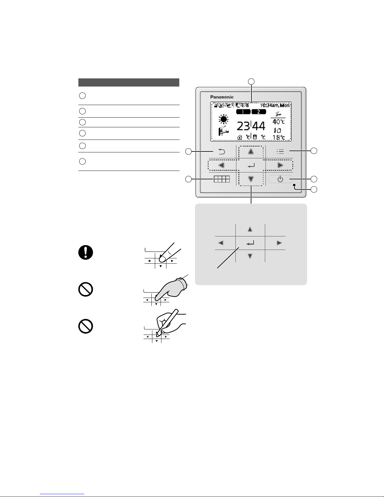
4.1.1 Remote Controller buttons and display
4
5
6
3
2
1
Buttons / Indicator
1
Quick Menu button
(For more details, refer to the separate
Quick Menu Guide.)
2
Back button
Returns to the previous screen
3 LCD Display
4
Main Menu button
For function setup
5
ON/OFF button
Starts/Stops operation
6
Operation indicator
Illuminates during operation, blinks during
alarm.
Press centre
No glove
No pen
Cross key buttons
Selects an item.
Enter button
Fixes the selected content.
Up
Down
thgiRtfeL

20
3 Temperature of each zone
4 Time and day
5 Water Tank temperature
6 Outdoor temperature
7 Sensor type/Set temperature type icons
Water Temperature
→Compensation curve
Water Temperature
→Direct
Pool only
Room Thermostat
→External
Room Thermostat
→Internal
Display
1 Mode selection
AUTO
• Depending on the preset outdoor
temperature, the system selects
HEAT or *
1
COOL operation mode.
Auto Heat Auto Cool
*
1,*2
COOL • The fan coil unit is either turned
ON or OFF.
• The outdoor unit provides cooling
to the system.
AUTO
+TANK
• Depending on the preset outdoor
temperature, the system selects
HEAT + TANK or *
1
COOL + TANK
operation mode.
Auto Heat Auto Cool
*
1,*2
COOL
+TANK
• The outdoor unit provides cooling
to the system.
• The system controls the booster
heater in the water tank.
HEAT
• The panel/floor HEAT operation is
either turned ON or OFF.
• The outdoor unit provides heat to
the system.
TAN K
• The water tank is either turned
ON or OFF.
• The outdoor unit provides heat to
the water tank.
HEAT
+TANK
• The outdoor unit provides heat to
the water tank and the system.
• This mode can be selected only
when the water tank is installed.
* The direction icons point to the currently
active mode.
• Room operation / Tank operation.
• Deice operation.
2
Operation icons
The status of operation is displayed.
Icon will not display (under operation OFF screen) whenever operation is OFF except weekly timer.
Holiday operation status Weekly Timer operation status Quiet operation status
Zone:Room Thermostat
→Internal sensor status
Powerful operation status
Demand Control or
SG ready or SHP status
Room Heater status Tank Heater status Solar status
Bivalent status
(Boiler)
*1 The system is locked to operate without COOL mode. It can be unlocked only by authorised installers or our authorised service partners.
*2 Only displayed when COOL mode is unlocked (This means when COOL mode is available).
2 43
1
5
6
7

21
4.1.2 Initialization
Before startingto install the various menu settings, please initiate the Remote Controller by selectingthe languageof
o
peration and installing the date and time correctly.
It is recommended that the installer conducts the following initialization of the Remote Controller.
Selecting the language
LCD blinking
Press and wait while the display is
initializing.
1
Scroll with
and to select the language.
2
Press
to confirm the selection.
Setting the clock
1
htiwtceleS
or how to display the time,
either 24h or am/pm format (for example, 15:00
or 3 pm).
2
Press
to confirm the selection.
3
Use
and to select year, month, day,
hour and minutes. (Press
to confirm the
selection each time.)
4
Oncethetimeisset,timeanddaywillappear
on the display even if the Remote Controller is
turned OFF.
22
4.1.3 Quick Menu
4.1.4 Menus (For user)
A
fter the initial settings have beencompleted, youcan select a quick menu from the followingoptions and edit the setting.
1
Press
to display the quick menu.
Force DHW Powerful Quiet Force Heater
Weekly Timer Force Defrost Error Reset R/C Lock
2
Use
to select menu.
3
Press
to turn on/off the select menu.
Select menus and determine settingsa
c
c
ordingto the system
available in the household. All initial settings must be done by an
authorised dealer or a specialist. It is recommended that all alterations
of the initial settings are also done by an authorised dealer or a
specialist.
• After initial installation, you may manually adjust the settings.
• The initial setting remains active until the user changes it.
• The Remote Controller can be used for multiple installations.
• Ensure the operation indicator is OFF before setting.
• The system may not work properly if set wrongly.
Please consult an authorised dealer.
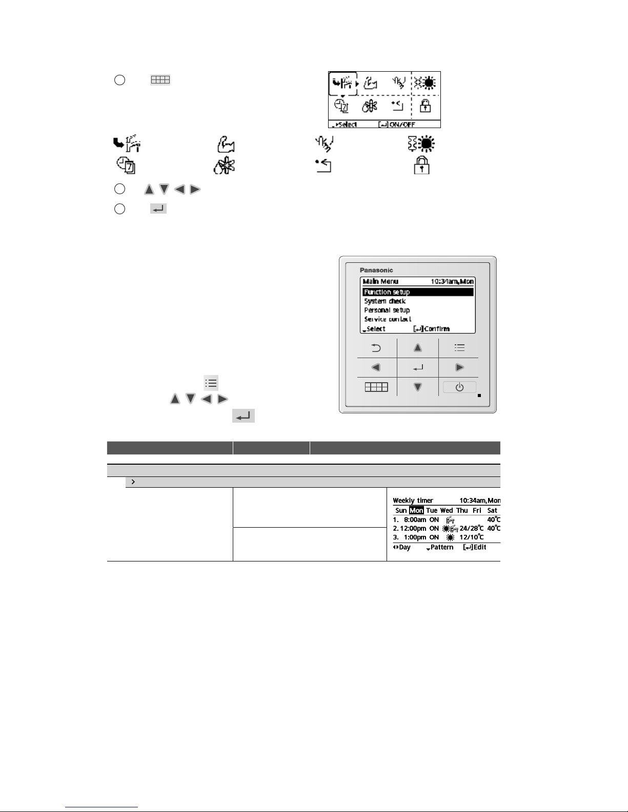
To display <Main Menu>:
To select menu:
To confirm the selected content:
yalpsiD/snoitpOgnitteSgnitteStluafeDuneM
1 Function setup
1.1
Weekly timer
Once the weekly timer is set up,
User can edit from Quick Menu.
Tosetupto6patternsof
operation on a weekly basis.
• Disabled if Heat-Cool SW is
pressed or if Force Heater
is on.
Timer setup
Select day of the week and
set the patterns needed
(Time / Operation ON/OFF / Mode)
Timer copy
Select day of the week

23
yalpsiD/snoitpOgnitteSgnitteStluafeDuneM
1.2
Holiday timer
To save energy, a holiday
period may be set to either turn
OFF the system or lower the
temperature during the period.
OFF
ON
Holiday start and end.
Date and time
OFF or lowered temperature
• Weekly timer setting may be temporarily disabled during Holiday timer setting
but it will be restored once the Holiday timer is completed.
1.3
Quiet timer
To operate quietly during the
preset period.
6 patterns may be set.
Level 0 means the mode is off.
Time to start Quiet :
Date and time
Level of quietness:
0~3
1.4
Room heater
To set the room heater ON or
OFF.
OFF
1.5
Tank heater
To set the tank heater ON or
OFF.
OFF
1.6
Sterilization
To set the auto sterilization ON
or OFF.
ON
• Do not use the system during sterilization in order to prevent scalding with hot water, or overheating of shower.
• Ask an authorised dealer to determine the level of sterilization function field settings according to the local laws and
regulations.
1.7
DHW mode (Domestic Hot Water)
To set the DHW mode to
Standard or Smart.
• Standard mode have faster
DHW Tank heat up time.
Meanwhile Smart mode
take longer time to heat up
DHW time with lower energy
consumption.
Standard
24
yalpsiD/snoitpOgnitteSgnitteStluafeDuneM
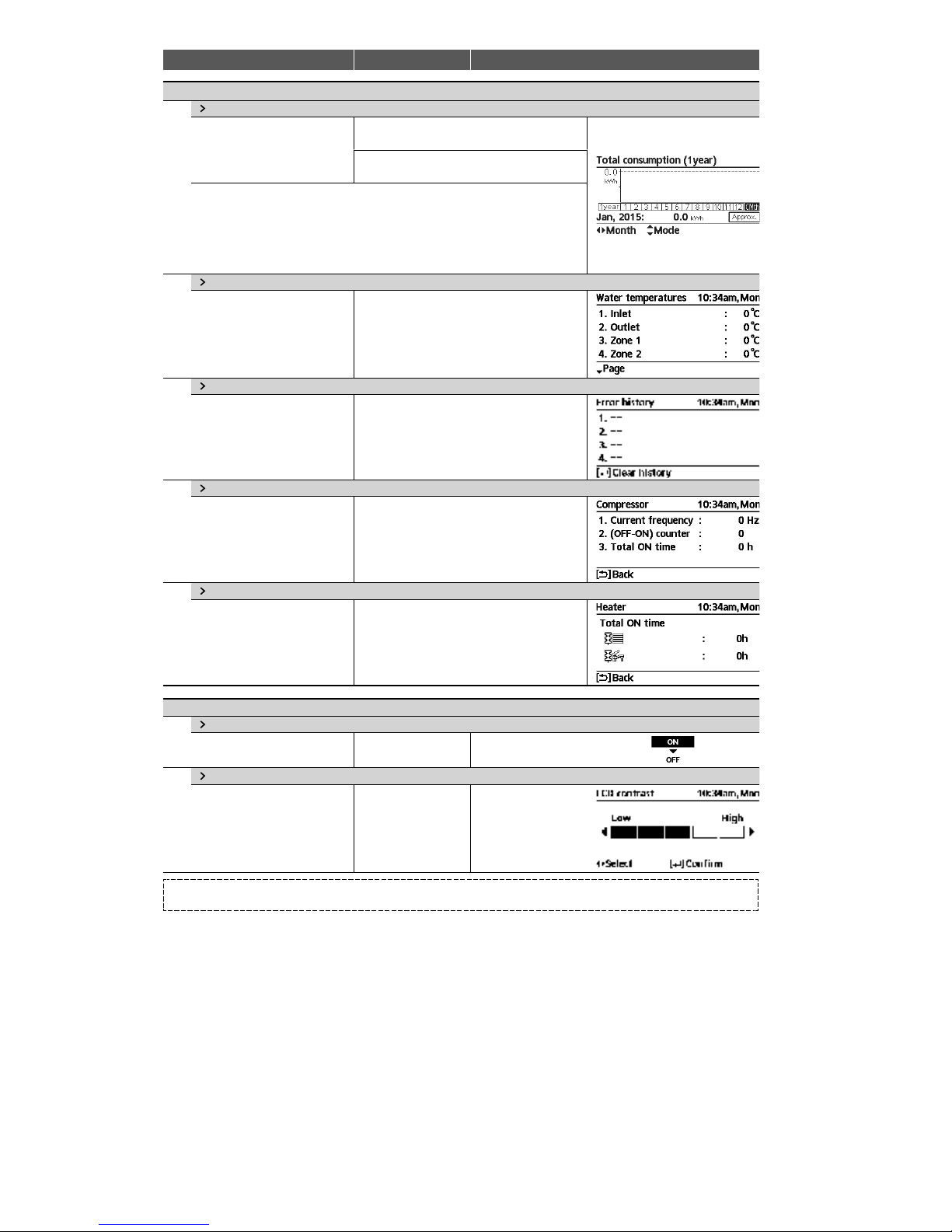
2 System check
2.1
Energy monitor
Present or historical chart of
energy consumption, generation
or COP.
Present
Select and retrieve
Historical chart
Select and retrieve
• COP= CoefficientofPerformance.
• For historical chart, the period is selected from 1 day/1 week/1year.
• Energy consumption (kWh) of heating, *
1
cooling, tank and total may be
retrieved.
• The total power consumption is an estimated value based on AC 230 V and
may differ from value measured by precise equipment.
2.2
Water temperatures
Shows all water temperatures in
each area.
Actual water temperature of 8 items:
Inlet / Outlet / Zone 1 / Zone 2 / Tank / Buffer
tank / Solar / Pool
Select and retrieve
2.3
Error history
• Refer to Troubleshooting for
error codes.
• The most recent error code is
displayed at the top.
Select and retrieve
2.4
Compressor
Shows the compressor
performance.
Select and retrieve
2.5
Heater
Total hours of ON time for
Room heater/Tank heater.
Select and retrieve
3 Personal setup
3.1
Touch sound
Turns the operation sound ON/
OFF.
ON
3.2
LCD contrast
Sets the screen contrast.
3
*1 The system is locked to operate without COOL mode. It can be unlocked only by authorised installers or our authorised service partners.
*2 Only displayed when COOL mode is unlocked (This means when COOL mode is available).

25
yalpsiD/snoitpOgnitteSgnitteStluafeDuneM
3.3
Backlight
Sets the duration of screen
backlight.
1min
3.4
Backlight intensity
Sets screen backlight
brightness.
4
3.5
Clock format
Sets the type of clock display.
24h
3.6
Date & Time
Sets the present date and time.
Year / Month / Day / Hour / Min
3.7
Language
Sets the display language for
the top screen.
• For Dutch, Greek, Finnish and
Turkish, please refer to the
English version.
ENGLISH / FRANÇAIS /
DEUTSCH / ITALIANO /
ESPAÑOL / DANISH /
SWEDISH / NORWEGIAN /
POLISH / CZECH
3.8
Unlock password
4 digit password for all the
settings.
0000
4 Service contact
4.1
Contact 1 / Contact 2
Preset contact number for
installer.
Select and retrieve

26
4.1.5 Menus (For installer)
yalpsiD/snoitpOgnitteSgnitteStluafeDuneM
5 Installer setup System setup
5.1
Optional PCB connectivity
To connect to the external PCB
required for servicing.
No
• If the external PCB is connected (optional), the system will have following additional functions:
1
Buffer tank connection and control over its function and temperature.
2
Control over 2 zones (including the swimming pool and the function to heat water in it).
3
Solar function (the solar thermal panels connected to either the DHW (Domestic Hot Water) Tank or the Buffer T ank.
4
External compressor switch.
5
External error signal.
6
SG ready control.
7
Demand control.
8
Heat-Cool SW
5.2
Zone & Sensor
To select the sensors and to
select either 1 zone or 2 zone
system.
Zone
• After selecting 1 or 2 zone system, proceed
to the selection of room or swimming pool.
• If the swimming pool is selected, the
temperature must be selected for
T temperature between 2 °C ~ 10 °C.
Sensor
* For room thermostat, there is a further
selection of external or internal.
5.3
Heater capacity
To reduce the heater power if
unnecessary.*
3kW/6kW/9kW
3kW
* Options of kW vary depending
on the model.
5.4
Anti freezing
To activate or deactivate the
water freeze prevention when
thesystemisOFF
Yes
5.5
Buffer tank connection
To connect tank to the system
and if selected YES, to set
T temperature.
• The optional PCB connectivity
must be selected YES to
enable the function.
• If the optional PCB
connectivity is not selected,
the function will not appear on
the display.
No
Yes
5°C Set
T for Buffer Tank
27
yalpsiD/snoitpOgnitteSgnitteStluafeDuneM
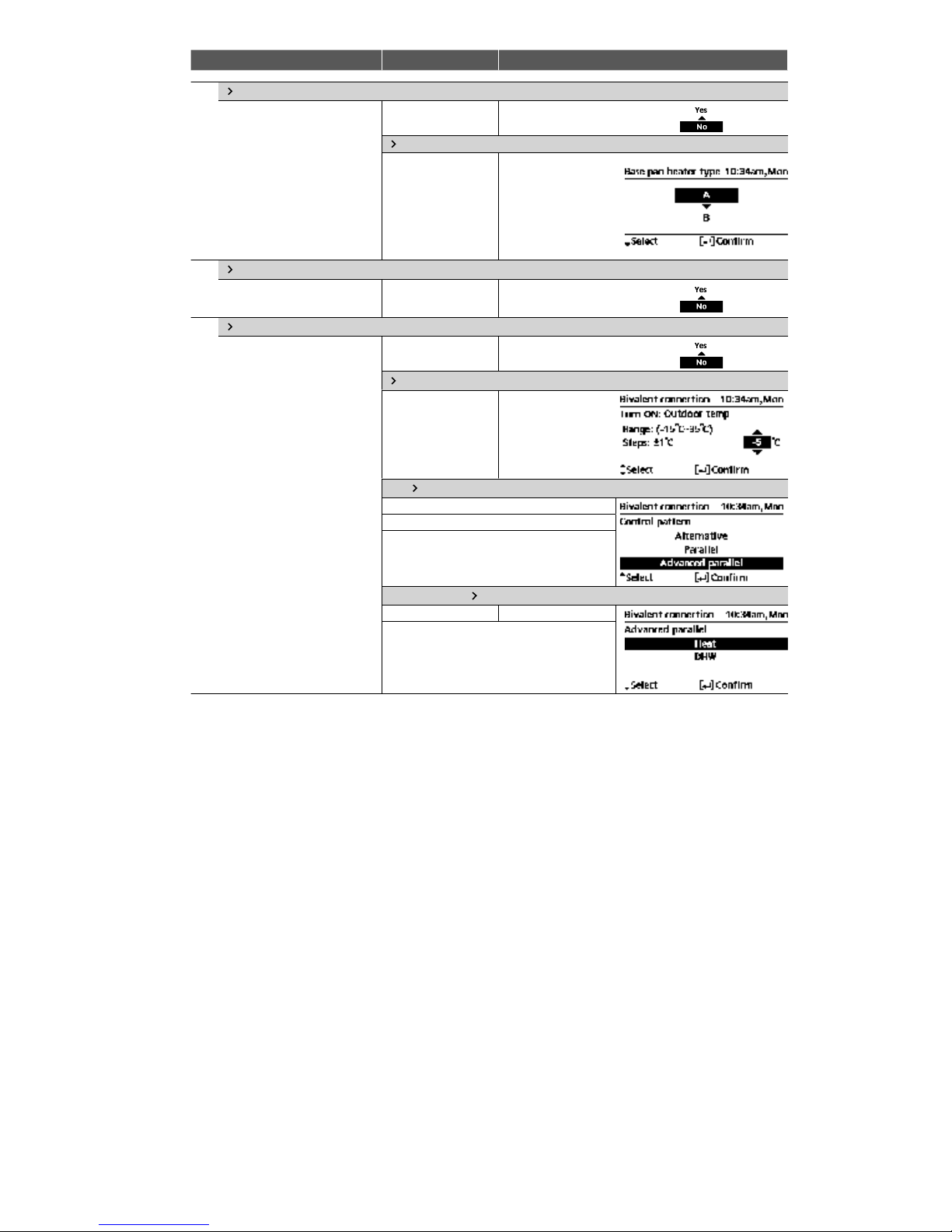
5.6
Base pan heater
To select whether or not
optional base pan heater is
connected.
retaehnapesabehT-AepyT*
activates only during
deice operation.
* Type B - The base pan heater
activates when outdoor
ambient temperature is
5°Corlower.
No
Yes
A
Set base pan heater
type*.
5.7
Alternative outdoor sensor
To select an alternative outdoor
sensor.
No
5.8
Bivalent connection
To select a bivalent connection
to allow an additional heat
source such as a boiler to heatup the buffer tank and domestic
hot water tank when heatpump
capacity is insufficientatlow
outdoor temperature. The
bivalent feature can be set-up
either in alternative mode
(heatpump and boiler operate
alternately), or in parallel
mode (both heatpump and
boiler operate simultaneously),
or in advance parallel mode
(heatpump operates and boiler
turns on for buffer-tank and/or
domestic hot water depending
on the control pattern setting
options).
No
Yes
-5 °C
Set outdoor
temperature for
turn ON Bivalent
connection.
Yes After selecting the outdoor temperature
Control pattern
Alternative / Parallel / Advanced parallel
• Select advanced parallel for bivalent use of
the tanks.
Control pattern
Advanced parallel
Heat Selection of the tank
• “Heat” implies Buffer Tank and “DHW”
implies Domestic Hot Water Tank.

28
yalpsiD/snoitpOgnitteSgnitteStluafeDuneM
Control pattern Advanced parallel Heat Yes
• Buffer Tank is activated only after selecting
“Yes”.
-8 °C
Set the temperature
threshold to start the
bivalent heat source.
0:30
Delay timer to start
the bivalent heat
source
(in hour and minutes).
-2 °C
Set the temperature
threshold to stop the
bivalent heat source.
0:30
Delay timer to stop
the bivalent heat
source
(in hour and minutes).
Control pattern Advanced parallel DHW Yes
• DHW Tank is activated only after selecting
“Yes”.
0:30
Delay timer to start
the bivalent heat
source
(in hour and minutes).
5.9
External SW
No
29
yalpsiD/snoitpOgnitteSgnitteStluafeDuneM
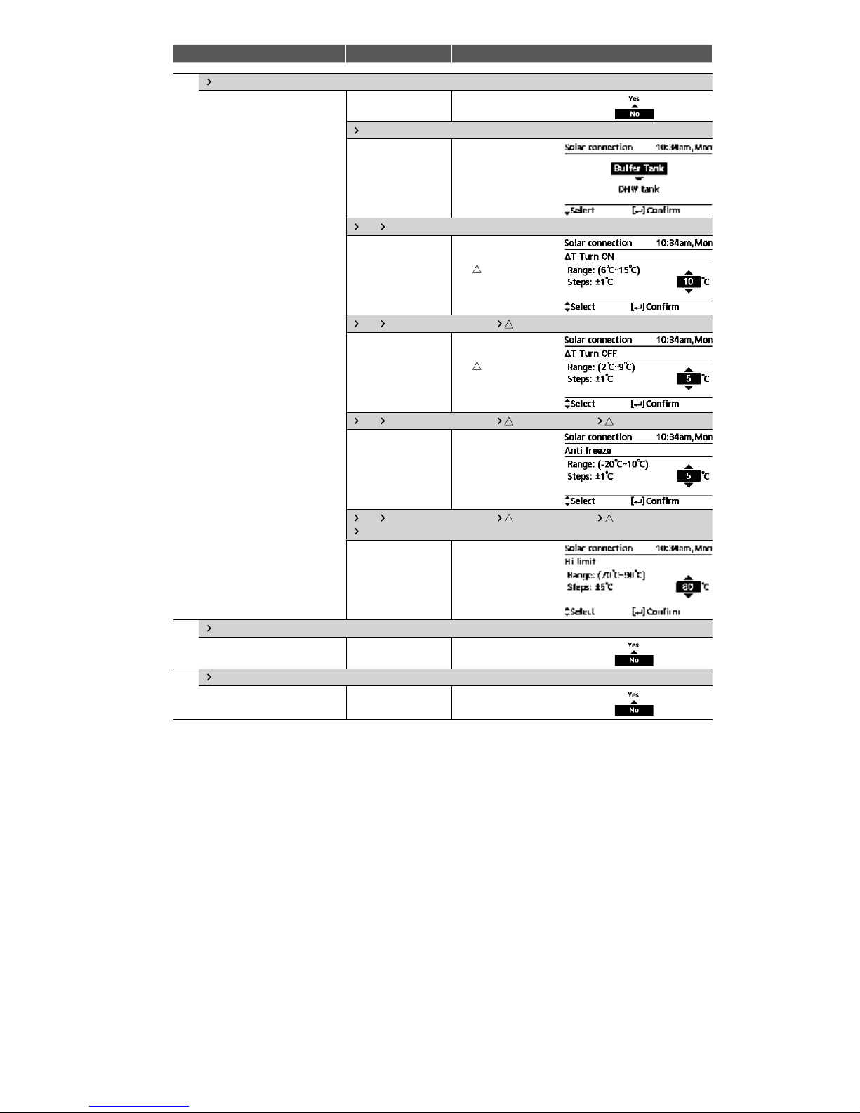
5.10
Solar connection
• The optional PCB connectivity
must be selected YES to
enable the function.
• If the optional PCB
connectivity is not selected,
the function will not appear on
the display.
No
Yes
Buffer tank Selection of the tank
Yes After selecting the tank
10 °C
Set
TON
temperature
Yes After selecting the tank T ON temperature
5°C
Set
TOFF
temperature
Yes After selecting the tank T ON temperature T OFF temperature
5°C
Set Antifreeze
temperature
Yes After selecting the tank T ON temperature T OFF temperature
After setting the antifreeze temperature
80 °C Set Hi limit
5.11
External error signal
No
5.12
Demand control
No
30
yalpsiD/snoitpOgnitteSgnitteStluafeDuneM
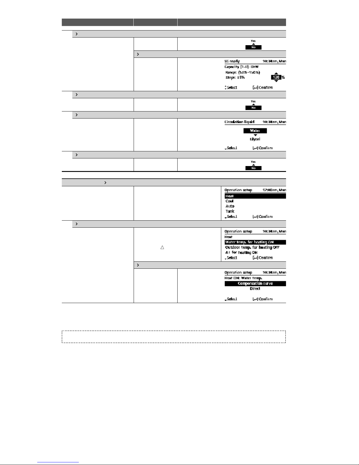
5.13
SG ready
No
Yes
120 %
Capacity (1) & (2) of
Buffer Tank and DHW
Tank (in % )
5.14
External compressor SW
No
5.15
Circulation liquid
To select whether to circulate
water or glycol in the system.
Water
5.16
Heat-Cool SW
No
6 Installer setup Operation setup
To access to the four major
functions or modes.
4mainmodes
Heat / *1,*2Cool / Auto / Tank
6.1
Heat
To set various water & ambient
temperatures for heating.
Water temp. for heating ON /
Outdoor temp. for heating OFF /
T for heating ON /
Outdoor temp. for heater ON
Watertemp.forheatingON
Compensation curve
Heating ON
temperatures in
compensation curve
or direct input.
*1 The system is locked to operate without COOL mode. It can be unlocked only by authorised installers or our authorised service partners.
*2 Only displayed when COOL mode is unlocked (This means when COOL mode is available).
 Loading...