

Page 1
Installation and Operating Instructions
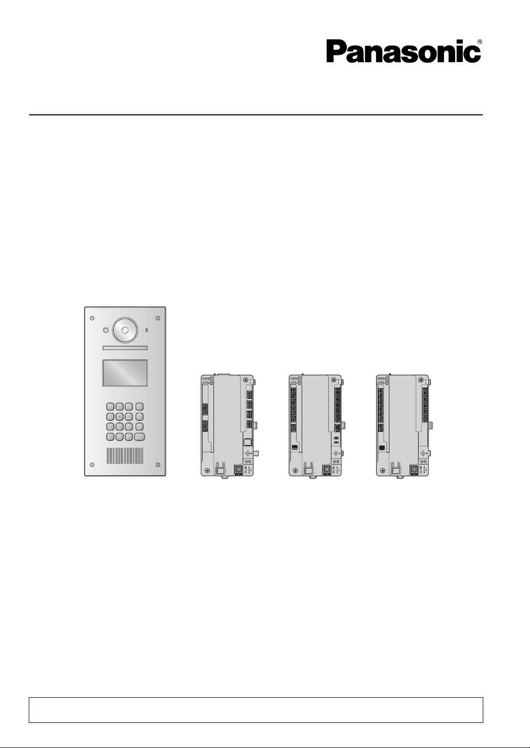
Video Intercom System for Apartment Complexes
Model No. VL-V900 and VL-V700 Series
VL-V900 VL-V700 VL-V701 VL-V702
Thank you for purchasing a Panasonic product.
Please follow all instructions in this document and save it for future reference.
This system is an auxiliary system; it is not designed to provide complete protection from property loss.
Panasonic will not be held responsible in the event that property loss occurs while this system is in operation.
Page 2

Table of Contents
1. Introduction
1.1 System overview ...........................................3
2. Important Information
2.1 Important safety information ..........................5
2.2 Privacy and rights of portrait .........................5
2.3 Data security .................................................5
2.4 Other information ..........................................6
2.5 For Europe ....................................................7
3. Preparation
3.1 Included items ...............................................8
3.2 Device diagrams .........................................10
3.3 Specifications ..............................................13
4. Installation
4.1 Installation cautions .....................................17
4.2 Installing the Power Supply Unit .................17
4.3 Installing the Lobby Station .........................19
4.4 Installing the Control Box/Distribution Box/Lift
Controller .....................................................22
4.5 Wiring Connections .....................................24
4.6 Connecting other devices ............................34
4.7 Basic settings ..............................................35
5. Programming
5.1 Programming overview ...............................36
5.2 PC programming .........................................36
5.3 Lobby station programming .........................42
5.4 Telephone programming .............................46
5.5 Main monitor programming .........................47
5.6 System log ..................................................49
5.7 Restarting a device .....................................50
5.8 POWER and ACCESS indicators ...............50
6. Basic Operations
6.1 System conditions and limitations ...............51
6.2 Lobby station operations .............................51
6.3 Facility staff operations ...............................52
7. Other Information
7.1 Basic troubleshooting ..................................53
7.2 Cleaning ......................................................53
7.3 Trademarks .................................................53
7.4 Terms and illustrations in this
document ....................................................53
2
Page 3

1. Introduction
1.1 System overview
This document explains how to install and configure a Video Intercom System for Apartment Complexes comprised
1. . Introduction
of the following devices.
R VL-V900 Lobby Station
R VL-V700 Control Box
R VL-V701 Distribution Box
R VL-V702 Lift Controller
Additionally, general information is provided for connecting other devices to the system.
1.1.1 Main features
Large-capacity, expandable
R The system supports up to 560 room units (main monitors) and 3 lobby stations.
R Optional devices such as cameras, access controllers (door openers, key switches, card scanners, etc.), electric
locks, and a TV monitor can be connected.
R The system can be integrated with a PBX system used by facility staff.
Easy to configure and maintain
R System settings can be configured in advance using a computer, and uploaded on-site via USB connection.
R System settings can be configured on-site using a lobby station, main monitor, and PBX extension telephone.
R System events can be logged on an optional SD card.
Convenient features for residents, visitors, and facility staff
R The system can be used in "room mode" (visitors can call rooms directly) or "reception mode" (visitors calls are
routed through a receptionist).
R Visitors can use a lobby station to call residents or facility staff.
R Residents can use their room units (main monitors) to monitor lobby stations and optional cameras, and can allow
visitors to enter the lobby and lift.
R Residents can use their main monitors to make emergency calls to facility staff. (VL-MVN511 or other compatible
main monitor is required.)
R Facility staff can make and receive calls to and from residents and visitors.
3
Page 4
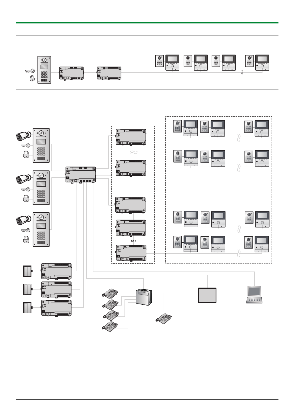
Distribution Box (1)
Lobby Station (1)
Control Box (1)
Room units (up to 20)
.
.
.
.
.
.
.
.
.
.
.
.
.
.
.
.
.
. . .
. . .
. . .
.
.
. . .
.
.
.
.
.
.
.
.
.
.
.
.
.
.
.
.
.
.
Distribution Box (up to 28)
(4 branches x 7 distribution boxes)
Lift Controller (up to 15)
(3 branches x 5 lift controllers)
Room units (up to 560)
(20 room units x 28 distribution boxes)
PBX (1)
Terminal (up to 4)
Emergency Terminal (1)
Lift
(up to 3)
Lobby Station (up to 3)
PC (1)
(programming)
TV monitor (1)
Repeater (up to 4)
Repeater
Security camera, access controller,
electric lock (1 each for each lobby station)
Control Box (1)
(4 distribution box branches,
3 lift controller branches)
1. Introduction
1.1.2 System configuration
Basic system example (up to 20 room units)
Fully expanded system example
4
Page 5
2.1 Important safety information
WARNING
CAUTION
To prevent severe injury and loss of life/property, read
2. . Important Information
this section carefully before using the product to ensure
proper and safe operation of your product.
Preventing fire and electric shock
R The product shall be installed by qualified service
personnel.
R Use only the power supply unit VL-PS240.
R Do not place objects on the power cord. Install the
product where no one can step or trip on the cord.
R Do not allow the power cord to be excessively pulled,
bent or placed under heavy objects.
R Make sure all connections from the power source to
the power supply unit are secure.
R Never touch the power supply unit with wet hands.
R Do not use the power supply unit for outdoor
installations (it is for indoor use only).
R Do not disassemble this product. Refer servicing to
an authorised service centre when service is
required. Opening or removing covers may expose
you to dangerous voltages or other risks.
R Do not touch the product and the power supply unit
during an electrical storm. There may be a remote
risk of electric shock from lightning.
R Never push any objects through slots in this product.
R Disconnect this product from the power source and
refer servicing to an authorised service centre when
the following conditions occur:
– If it emits smoke, an abnormal smell or makes
unusual noise.
– If the power cord is damaged or frayed.
– If metal objects have been dropped inside the
product.
Preventing accidents
R SD cards may become a choking hazard. Keep SD
cards out of reach of children. If you suspect a child
has swallowed an SD card, seek medical advice
immediately.
R Make sure you turn off the power at the breaker
before performing any wiring work.
R Always connect AC or DC cables to the appropriate
connection terminals. Incorrectly connecting the AC
or DC cables may damage the power supply unit.
R To prevent the power cables from disconnecting and
to prevent electric shock, secure the power cables
using the cable binders (accessory) and attach the
cable covers.
2. Important Information
Insert the power cables firmly all the way into the
R
terminals. If the cables are not inserted all the way,
heat may be generated.
R If the wiring is outdoors, use a protection tube and a
surge protector.
R If the wiring is underground, use a protection tube
and do not make any connections underground.
R Install the product securely adhering to the
instructions in this manual to prevent it from falling off
the wall. Avoid installing onto low-strength walls,
such as gypsum board, ALC (autoclaved lightweight
concrete), concrete block, or veneer (less than
18 mm thick) walls.
R The power supply unit is used as the main disconnect
device. Ensure that the power source is installed near
the product and is easily accessible.
R Do not put your ear(s) near the speaker, as loud
sounds emitted from the speaker may cause hearing
impairment.
R When using this product, basic safety precautions
should always be followed to reduce the risk of fire,
electric shock, or personal injury.
1. Do not use this product (excluding the lobby
station) near water. For example, near a bathtub,
wash bowl, kitchen sink, or laundry tub, in a wet
basement, or near a swimming pool, and the like.
2. Use only the power supply unit indicated in this
document.
SAVE THESE INSTRUCTIONS
2.2 Privacy and rights of portrait
When installing or using the product, please take into
consideration the rights of others with regard to privacy.
R It is generally said that "privacy" means the ability of
an individual or group to stop information about
themselves from becoming known to people other
than those whom they choose to give the information.
"Rights of portrait" means the right to be safe from
having your own image taken and used
indiscriminately without consent.
2.3 Data security
In order to use the system safely and correctly, the data
security guidelines (listed below) must be observed.
Failure to do so may result in the following.
R Loss, leakage, falsification or theft of user
information.
R Unauthorised or illegal use of the system by a third
party.
R Interference or suspension of service caused by a
third party.
What is user information?
User information is defined as the following types of
information.
1. Information stored on the SD memory card
5
Page 6
1
2. Important Information
– System event information
– Doorphone camera images
2. Information stored in the control box and lobby station
– Resident names and room numbers
– System settings
3. Information stored on the computer that is used by
the setup tool
– Resident names and room numbers
– System settings
Data security guidelines
R Do not allow unauthorised access to the control
box and its SD memory card.
The control box should be installed in a restricted
access location, where only authorised personnel
may gain access through the use of a special tool,
lock and key, or other means of security.
Note that the SD memory card, which contains a log
of all system event information, can be removed by
anyone with access to the control box.
R Observe proper management of passwords,
access codes, etc.
Access codes can be used to program the system,
open doors, etc. Select codes that are difficult to
guess, change them regularly, and keep them secret.
R Protect user information when sending the
control box or lobby station to be repaired, or
when handing them over to a third party.
Remove the SD memory card from the control box.
Keep it in a secure place until lit is needed again.
Use the setup tool to download all data stored in the
control box and lobby station. (This will back up all
data and save it on your computer.) Then use the
setup tool to upload blank configuration files (i.e., files
that contain no user information) to the control box or
lobby station.
R Protect user information stored on the computer
used to configure the system.
When user information is sent stored on a computer,
the confidentiality of that information becomes the
responsibility of the customer. Before disposing of
the computer, ensure that data cannot be retrieved
from it by formatting the hard disk and/or rendering it
physically unusable.
R Protect user information when disposing of the
control box or lobby station.
Remove the SD memory card from the control box.
Render it physically unusable and dispose of it.
Use the setup tool to upload blank configuration files
(i.e., files that contain no user information) to the
control box or lobby station.
The recorded images may be lost when:
R
– Mishandled
– Electric shock or radio wave interference occurs.
– The power is turned off during use.
R To the maximum extent permitted by law, Panasonic
assumes no responsibility for injuries or property
damage resulting from failures arising out of improper
installation or operation inconsistent with this
document.
Disposal of Old Equipment (Only for European Union
and countries with recycling systems)
This symbol (A) on the products, packaging, and/or
accompanying documents means that used electrical
and electronic products must not be mixed with general
household waste.
For proper treatment, recovery and recycling of old
products, please take them to applicable collection
points in accordance with your national legislation.
By disposing of them correctly, you will help to save
valuable resources and prevent any potential negative
effects on human health and the environment. For more
information about collection and recycling, please
contact your local municipality.
Penalties may be applicable for incorrect disposal of this
waste, in accordance with national legislation.
Information on Disposal in other Countries outside
the European Union
This above symbol (A) is only valid in the European
Union. If you wish to discard this product, please contact
your local authorities or dealer and ask for the correct
method of disposal.
2.4 Other information
R If you stop using the product, remote it from the walls
to prevent it from falling off.
R When power fails, this product cannot be used.
R Panasonic may not be liable for damages due to
external factors such as power failures.
6
Page 7
2.5 For Europe
We declare under our sole responsibility that the product
to which this declaration relates is in conformity with the
standard or other normative document following the
provisions of Directive 2004/108/EC.
Ecodesign information
Ecodesign information under EU Regulation (EC) No.
1275/2008 amended by (EU) Regulation
No. 801/2013. From 1 January 2015.
Please visit here: www.ptc.panasonic.eu
Click [Downloads] ® [Energy related products
information (Public)]
Power consumption in networked standby and guidance
are mentioned in the web site above.
Authorised Representative in EU:
2. Important Information
Panasonic Testing Centre
Panasonic Marketing Europe GmbH
Winsbergring 15, 22525 Hamburg, Germany
7
Page 8
3. Preparation
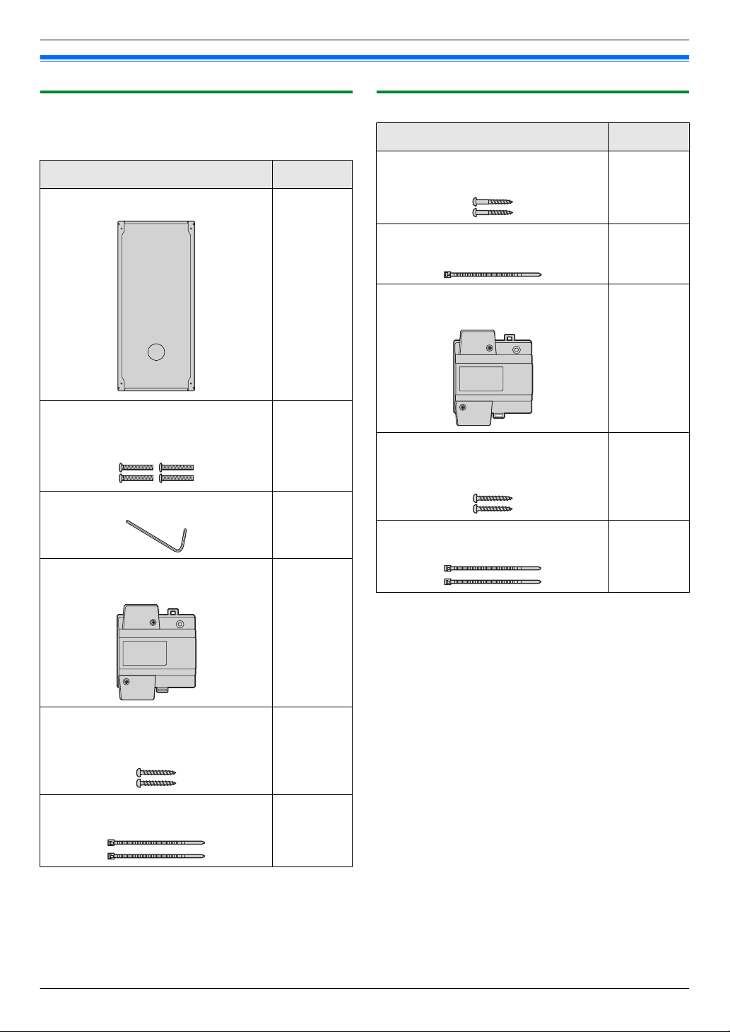
3.1 Included items
3. . Preparation
3.1.1 Lobby Station
3.1.2 Control Box
Additional items required for installation are noted on
page 9.
Item Quantity
Flush mount box 1
Screw (for securing the lobby station to
the flush mount box)
4 mm ´ 25 mm
Hex wrench 1
Power supply unit
VL-PS240
4
1
Item Quantity
Screw (for mounting the box)
3.8 mm ´ 20 mm
Cable binder (for securing the
connected wires)
Power supply unit
VL-PS240
Screw (for mounting the power supply
unit)
4 mm ´ 40 mm
Cable binder (for securing the AC and
DC cables)
2
1
1
2
2
Screw (for mounting the power supply
unit)
4 mm ´ 40 mm
Cable binder (for securing the AC and
DC cables)
8
2
2
Page 9
3. Preparation
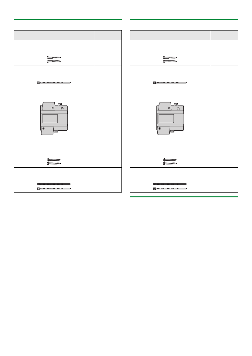
3.1.3 Distribution Box
Item Quantity
Screw (for mounting the box)
3.8 mm ´ 20 mm
Cable binder (for securing the
connected wires)
Power supply unit
VL-PS240
Screw (for mounting the power supply
unit)
4 mm ´ 40 mm
3.1.4 Lift Controller
Item Quantity
2
1
1
2
Screw (for mounting the box)
3.8 mm ´ 20 mm
Cable binder (for securing the
connected wires)
Power supply unit
VL-PS240
Screw (for mounting the power supply
unit)
4 mm ´ 40 mm
2
1
1
2
Cable binder (for securing the AC and
DC cables)
2
Cable binder (for securing the AC and
DC cables)
2
3.1.5 Additional items
The following items are also required for installation and
are not included.
– Power cables
Used to connect power supply units to lobby stations,
the control box, distribution boxes, and lift controllers.
For details, see page 28.
– Signal wires
Used to connect lobby stations, the control box,
distribution boxes, lift controller, main monitors, and
other devices. For details, see page 28.
– SD card
Used to log system event information. For details,
see page 49.
9
Page 10
G
H
I
J
K
A
C
B
D
E
F
ONOFF
V700 K-IN K-OUT
L1 L2 C1C2 S1 S2
H
I
J
A
G
F
B
C
D
E
3. Preparation
3.2 Device diagrams
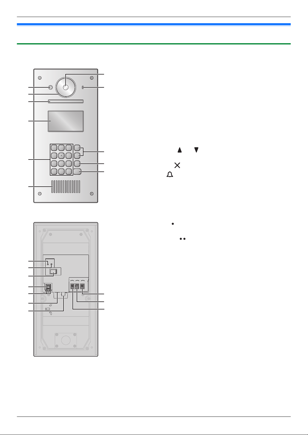
3.2.1 Lobby Station
Front view
A Heat sensor
Turns on the display when a visitor is detected.
B Lens cover
C Light
Illuminates subjects in dark environments.
D Display
E Keypad
F Speaker
G Camera lens
H Microphone
I
Search buttons ( and )
Used to select items shown on the display.
J
Cancel button ( )
K
Call button ( )
Rear view
Reset button ( )
A
Used when restarting the lobby station.
B Function button ( )
For internal use only.
C Power switch
D Cable release button for DC power supply cable
E Connection terminals for power supply
F USB port
For internal use only.
G Coaxial connector for external camera
H Connection terminals (output) for electric lock (K-OUT)
Used to send signals to the electric lock.
I Connection terminals (input) for access controller (K-IN)
Used to receive signals from the access controller.
J Connection terminals for control box (V700)
10
Page 11
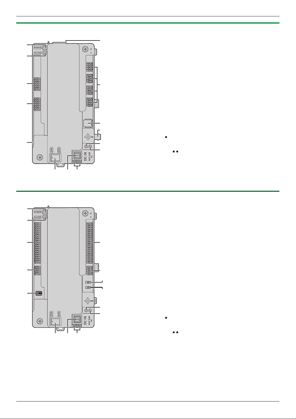
3.2.2 Control Box
H
N
G
F
K
J
I
C
A
B
D
E
L M
K
J
F
G
L N
C
D
E
A
B
H
I
M
3. Preparation
A Power indicator (POWER)
See 5.8.1 Control box indicators (Page 50).
B Access indicator (ACCESS)
See 5.8.1 Control box indicators (Page 50).
C Connection terminals for lobby stations
D Connection terminals for lift controllers
E USB port (underneath dust cover)
USB 2.0, standard-B connector. Used for PC programming.
F SD card slot
Used to save the system log.
G Connection terminals for distribution boxes
H RJ11 jack for connection to PBX
I Coaxial connector for external TV monitor
J Reset button ( )
Used when restarting the control box.
K Function button ( )
For internal use only.
L Power switch
M Cable release button for DC power supply cable
N Connection terminals for DC power supply
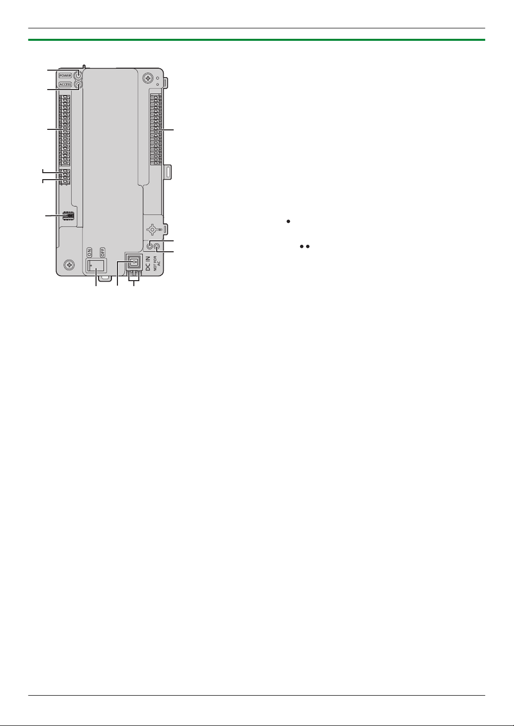
3.2.3 Distribution Box
Power indicator (POWER)
A
See 5.8.2 Distribution box indicators (Page 50).
B Access indicator (ACCESS)
See 5.8.2 Distribution box indicators (Page 50).
C Connection terminals for main monitors
D Connection terminals (input) for control box or distribution
box
E DIP switches
See page 29.
F Connection terminals for main monitors
G Connection terminals (output) for distribution box
H Terminate switch
See page 29.
I Repeater switch
See page 29.
J Reset button ( )
Used when restarting the distribution box.
K Function button ( )
For internal use only.
L Power switch
M Cable release button for DC power supply cable
N Connection terminals for DC power supply
11
Page 12
I
C
A
B
J
D
E
F
G
H
L
K
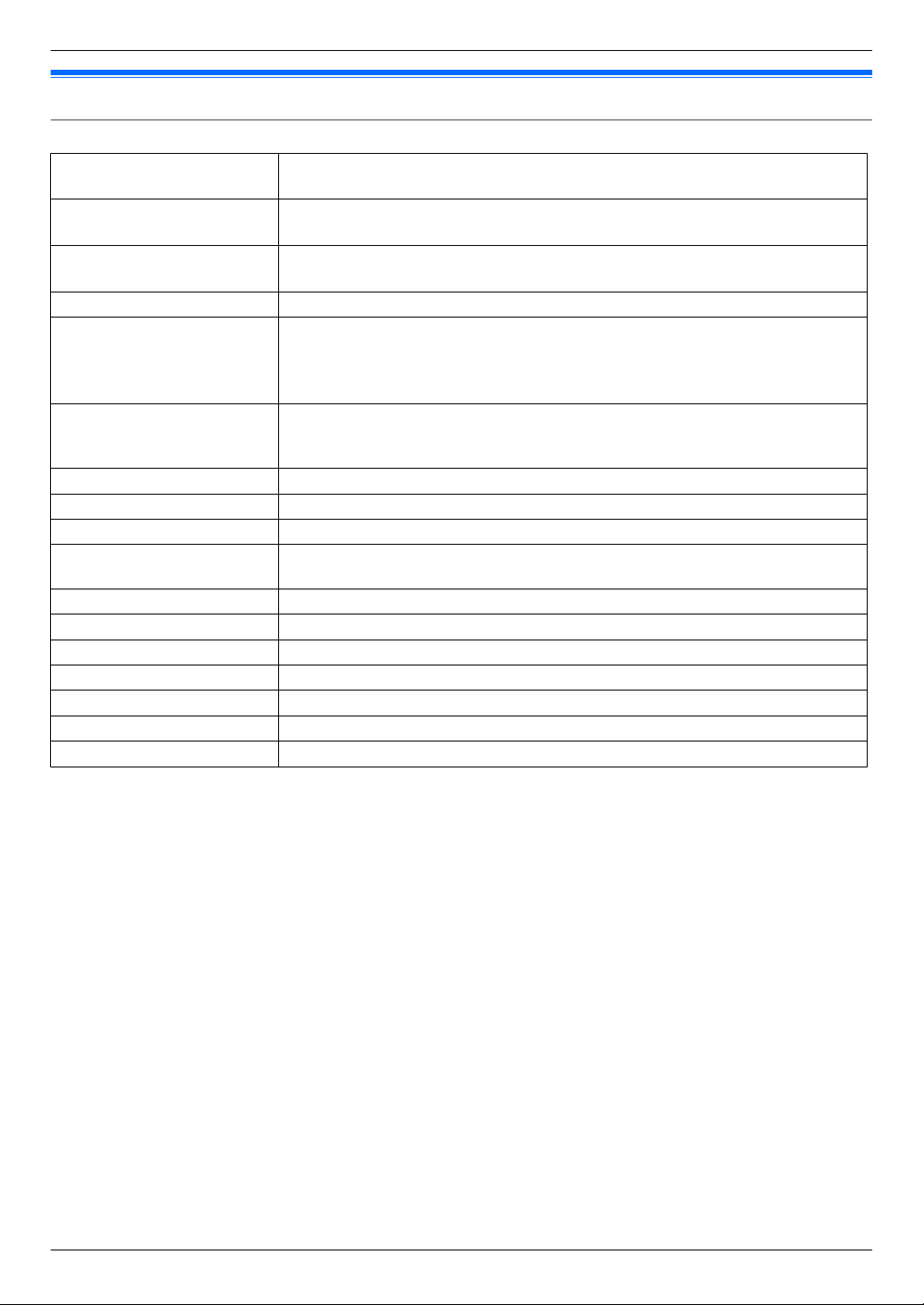
3. Preparation
3.2.4 Lift Controller
A Power indicator (POWER)
See 5.8.3 Lift controller indicators (Page 50).
B Access indicator (ACCESS)
See 5.8.3 Lift controller indicators (Page 50).
C Connection terminals for lifts
D Connection terminals (output) for lift controller
Used to send signals to a lift controller.
E Connection terminals (input) for control box or lift controller
Used to receive signals from the control box or a lift controller.
F DIP switches
See page 32.
G Connection terminals for lifts
H Reset button ( )
Used when restarting the lift controller.
I Function button ( )
For internal use only.
J Power switch
K Cable release button for DC power supply cable
L Connection terminals for DC power supply
12
Page 13
3. Preparation
3.3 Specifications
Lobby Station (VL-V900)
Power source Power supply unit (VL-PS240: 220 – 240 V AC, 0.2 A, 50 / 60 Hz)
24 V DC, 0.2 A
Power consumption Standby: Approx. 1.9 W
Operating: Approx. 4.5 W
Dimensions (mm)
(height ´ width ´ depth)
Mass (weight) Approx. 2.0 kg
Operating environment Ambient temperature for lobby station: approx. -10 °C to +55 °C
Display Approx. 10.92 cm (4.3 inches) monochrome display (white backlit LCD)
Installation method Flush mount (flush mounting box supplied)
External material Stainless steel (partially ABS and PC)
Talking method Hands-free
Heat sensor Pyroelectric sensor installed (detecting human body, part of the stations become
Image sensor 6.35 mm (1/4 inch) CMOS sensor (approx. 1M pixels)
Viewing angle Super wide view (H: approx. 170° / V: approx. 115°)
Minimum illuminance 1 lx
Lighting method White coloured LED lights
Waterproof property IP55
Vandal proof property Compliant with IK07
Display languages English
Approx. 373 ´ 179 ´ 2.5 (excluding sections embedded into the wall)
Ambient temperature for power supply unit: approx. 0 °C to +50 °C
Relative humidity: up to 90% (non-condensing)
(outdoor installation available; power supply unit is for indoor use only)
Display the date, room number inputted by visitors, how to use, name of residents,
and custom item
luminous)
13
Page 14
3. Preparation
Control Box (VL-V700)
Power source Power supply unit (VL-PS240: 220 – 240 V AC, 0.2 A, 50 / 60 Hz)
24 V DC, 0.2 A
Power consumption Standby: Approx. 3.5 W
Operating: Approx. 3.7 W
Dimensions (mm)
(height ´ width ´ depth)
Mass (weight) Approx. 400 g
Operating environment Ambient temperature: approx. -10 °C to +50°C
Installation method Wall mount or attach to DIN rail
External material ABS (flame retardant ABS resin)
Log Text log
Supported functions R USB 2.0 connection (to computer)
Connectivity
To distribution box
To lift controller
To monitor
To PBX
Approx. 210 ´ 108.5 ´ 52.5 (excluding protruding sections)
Ambient temperature for power supply unit: approx. 0 °C to +50°C
Relative humidity: up to 90% (non-condensing)
Indoor installation only
Save the text logs in the external SD memory card more than 90000 items (date,
caller, receiver, operation, status)
Image log
Save the image logs in the external SD memory card up to 90000 images (over
write save) (visitors call)
Supported operating systems: Microsoft® Windows® 7, Windows 8,
Windows 8.1, Windows 10
R Date and time setting (HH:MM DD/MM/YYYY)
R Download/upload the name of residents, room number, and monitor setting
R Output the system configuration data
R Estimate the status of equipment in the system
R Operation setting (Terminal, terminal and camera name, pass code, and so
on)
R Supported language: English (for administrators)
R Video output up to 1 (NTSC)
R RJ-11 PBX terminal function (connected to PBX system to guard station)
To lobby stations
Number of connectable stations: 3
Wire: 1 pair PE insulation, thickness of one conductor is from 0.65 – 1.2 mm
Distance: up to 200 m (in case of 1.2 mm thickness)
Number of connectable stations: 4 directly (including the repeaters)
Wire: 2 pair PE insulation, thickness of one conductor is from 0.65 – 1.2 mm
Distance: up to 200 m (in case of 1.2 mm thickness)
Number of connectable stations: 3 directly
Wire: 1 pair PE insulation, thickness of one conductor is from 0.65 – 1.2 mm
Distance: up to 200 m (in case of 1.2 mm thickness)
Number of connectable stations: 1 (NTSC)
Distance: based on camera specification
RJ-11 jack
Distance: comply with the PBX specification
14
Page 15
USB
USB 2.0, standard-B connector
SD card
4–64 GB SDHC / SDXC memory card is supported
Whole system capacity R Lobby station (VL-V900
R Main monitor (VL-MW251, VL-MVN511, VL-MV26): up to 560
(The maximum, for each branch, 7 distribution boxes, 1 repeater, and 140
main monitors can be connected.)
R Lift controller (VL-V702): up to 3 branches, totally up to 15 lift controllers
R Guard stations: up to 4 (in case of connecting to the PBX system)
Distribution Box (VL-V701)
Power source Power supply unit (VL-PS240: 220 – 240 V AC, 0.2 A, 50 / 60 Hz)
24 V DC, 0.1 A
Power consumption Standby: Approx. 1.2 W
Operating: Approx. 2.0 W
Dimensions (mm)
(height ´ width ´ depth)
Mass (weight) Approx. 400 g
Operating environment Ambient temperature: approx. -10 °C to +50 °C
Installation method Wall mount or attach to DIN rail
External material ABS (flame retardant ABS resin)
Connectivity To main monitor
Approx. 210 ´ 108.5 ´ 52.5 (excluding protruding sections)
Ambient temperature for power supply unit: approx. 0 °C to +50 °C
Relative humidity: up to 90% (non-condensing)
Indoor installation only
Number of connectable stations: 20
Wire: 1 pair PE insulation, thickness of one conductor is from 0.65 – 1.2 mm
Distance: up to 200 m (in case of 1.2 mm thickness)
To control box
Number of connectable stations: 1
Wire: 2 pair PE insulation, thickness of one conductor is from 0.65 – 1.2 mm
Distance: up to 200 m (in case of 1.2 mm thickness)
To distribution box
Number of connectable stations: 1
Wire: 2 pair PE insulation, thickness of one conductor is from 0.65 – 1.2 mm
Distance: up to 200 m (in case of 1.2 mm thickness)
): up to 3
3. Preparation
Lift Controller (VL-V702)
Power source Power supply unit (VL-PS240: 220 – 240 V AC, 0.2 A, 50 / 60 Hz)
24 V DC, 0.2 A
Power consumption Standby: Approx. 0.4 W
Operating: Approx. 4.4 W
Dimensions (mm)
(height ´ width ´ depth)
Mass (weight) Approx. 400 g
Operating environment Ambient temperature: approx. -10 °C to +50 °C
Installation method Wall mount or attach to DIN rail
Approx. 210 ´ 108.5 ´ 52.5 (excluding protruding sections)
Ambient temperature for power supply unit: approx. 0
Relative humidity: up to 90% (non-condensing)
Indoor installation only
°C to +50 °C
15
Page 16

3. Preparation
External material ABS (flame retardant ABS resin)
Connectivity To control box
Number of connectable stations: 1
Wire: 1 pair PE insulation, thickness of one conductor is from 0.65 – 1.2 mm
Distance: up to 200 m (in case of 1.2 mm thickness)
To lift
Number of outputs to lift: 20
To lift controller
Number of outputs to lift controller: 1
16
Page 17
CAUTION
45 mm
7 mm
25 mm
7 mm
B
A
4. Installation
4.1 Installation cautions
4. . Installation
R Make sure you turn off the power at the breaker before performing any wiring work.
R Always connect AC or DC cables to the appropriate connection terminals. Incorrectly connecting the AC or DC
cables may damage the power supply unit.
R To prevent the power cables from disconnecting and to prevent electric shock, secure the power cables using the
cable binders (accessory) and attach the cable covers.
R If the wiring is outdoors, use a protection tube or a surge protector.
R If the wiring is underground, use a protection tube and do not make any connections underground.
R Install the product securely adhering to the instructions in this document to prevent it from falling off the wall. Avoid
installing onto low-strength walls, such as gypsum board, ALC (autoclaved lightweight concrete), concrete block,
or veneer (less than 18 mm thick) walls.
4.2 Installing the Power Supply Unit
The following 2 methods can be used for installation.
– mounting on a DIN rail
– attaching directly to a wall
About the installation location
R The device must be installed inside an electrical panel or cabinet.
R A readily accessible disconnect device shall be incorporated external to the equipment.
– The external disconnect device must be certified, and have a creepage and clearance distance of 3 mm or
more.
Connecting the power cables (AC and DC cables)
Connect the power supply unit (accessory) and AC and DC cables (user supplied).
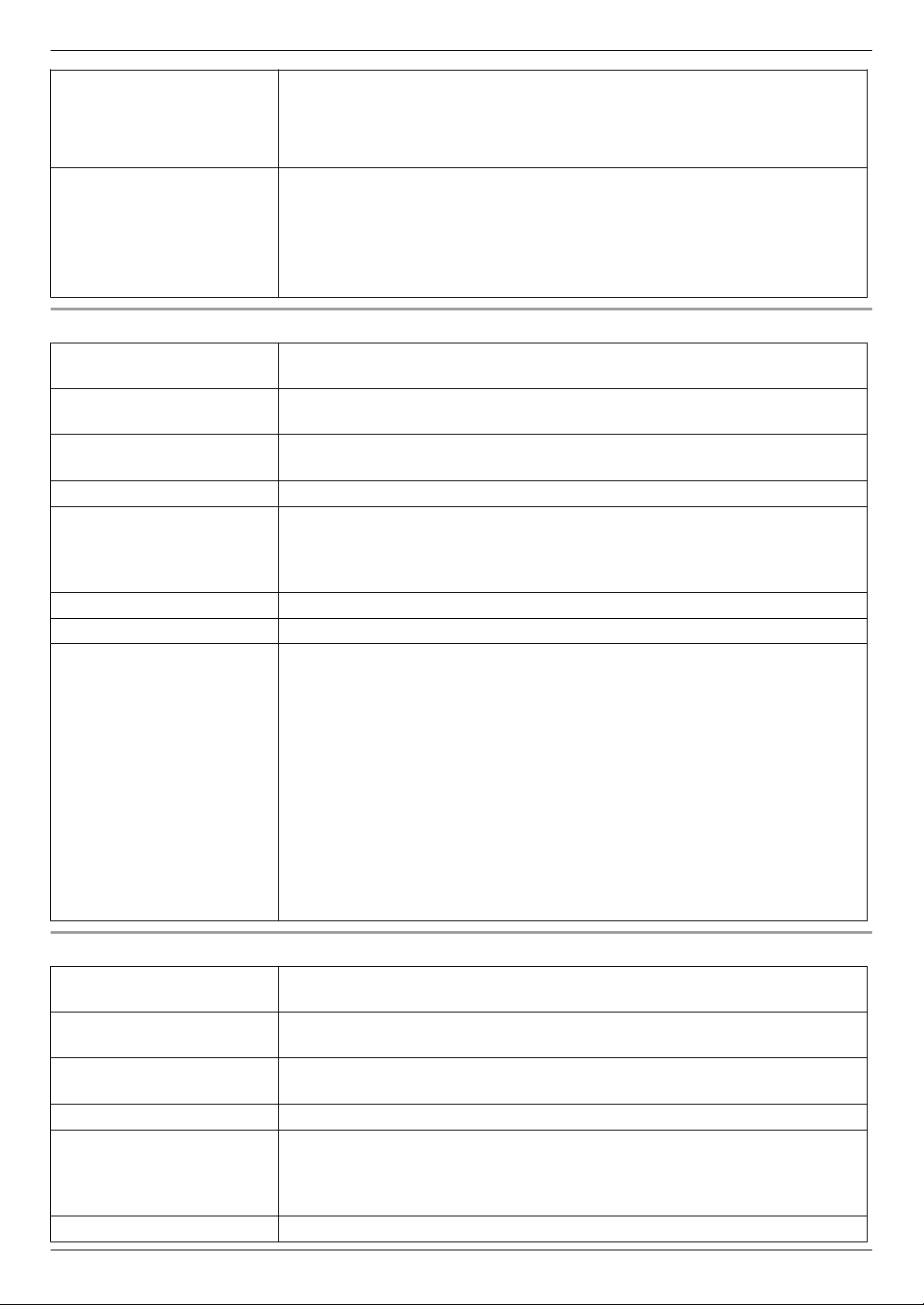
1. Strip the AC and DC cables as follows:
AC cable DC cable
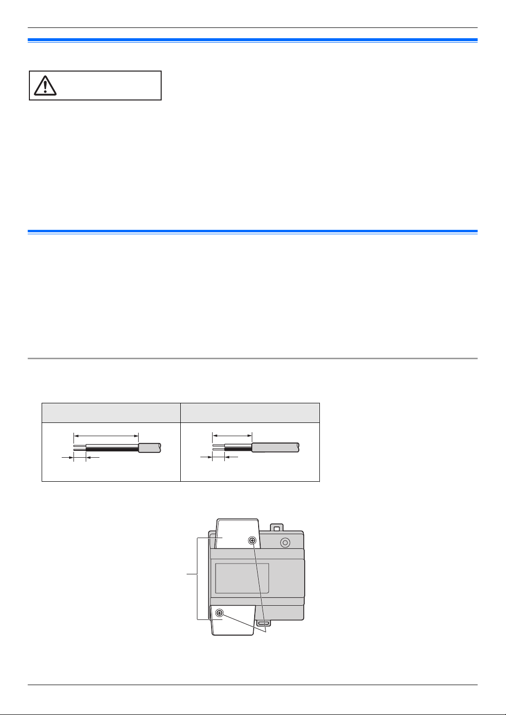
2. Remove the screws (A) and then remove the cable covers (B).
17
Page 18

C
AC cable
binder hole
AC IN terminal
DC cable
binder hole
DC OUT terminal
CAUTION
C
E
D
B
A
4. Installation
3. Connect the AC cable to the AC IN terminal on the top of the power unit, and the DC cable to the DC OUT terminal
on the bottom of the power supply unit, and then securely fasten the screws (C).
Top view
*1
View with the cable covers removed.
*1
R Recommended torque:
– AC terminal: 0.4 N·m {4.1 kgf·cm}
– DC terminal: 0.45 N·m {4.6 kgf·cm}
Front view
*1
Bottom view
*1
Front view
R Insert the AC and DC cables firmly all the way into the terminals. If the cables are not inserted all the way, heat
may be generated.
4. Use the cable binders (accessory) to secure the AC and DC cables (double-coated area) to the power supply unit.
5. Make sure to replace the cable covers (B) and then securely fasten the screws (A).
Mounting on a DIN rail
Follow the procedure in the order described below so that hook (A) is positioned at the bottom.
1. Hang the top hooks (B) on the DIN rail (C).
2. Pull and hold the lever down (D).
3. Secure the bottom hook (A) to the DIN rail (E).
18
Page 19

A
4. Installation
Attaching directly to a wall
Attach the power supply unit to the wall securely using the 2 supplied screws (A).
4.3 Installing the Lobby Station
Before installation
R Do not install the lobby station in the following locations. There may be a risk of malfunction or communication
disturbances.
– Places where vibration, impact, or echoing occurs.
– Places near a high concentration of dust, hydrogen sulphide, ammonia, sulphur, or noxious fumes.
– Places where there is excessive smoke, dust, and high temperature.
– Places exposed to direct sunlight.
– Places where most of the background is the sky.
– Places where the background is a white wall, and direct sunlight will reflect off it.
19
Page 20

Approx. 2300 mm
Image range
Approx. 115°
Approx. 500 mm
Approx.
Approx.
Approx. 1500 mm
Centre of
the Camera
lens
1600 mm
700 mm
Approx. 500 mm
Approx. 170°
353 mm
159 mm
80 mm
4. Installation
Installation position of the lobby station and camera range
Views when the camera is facing forwards at 0°. Example: Installation height is 1500 mm.
R The measurements and angles shown here are for reference purposes and may vary depending on the
environment.
Side view
Top view
(view when looking from above)
Note:
R Install the lobby station so that the lobby station is not exposed to strong light. If strong light shines on the lobby
station, the visitor’s face may not be distinguishable.
Installation
1. Open a hole in the wall for the flush mount box.
R Note the drilling dimensions of the wall surface of the flush mount box.
Front view
Side view
20
Page 21

A
DB E F G
C
H
I
9 mm
40 mm or more
12 mm
4. Installation
2. Open the knockout holes of the flush mount box, and then pass all necessary cables and wires (DC cable, wires
for control box, access controller, electric lock, etc.) through the knockout holes.
Mount the box in the wall.
3.
4. Connect the wires and cables to the lobby station.
R Strip the wires and cables as shown below.
R See 4.5.1 Wiring schematics (Page 24) for wiring schematic diagrams.
A
Cable release button for DC power
supply cable
B DC cable from power supply unit
C Hooks for securing the DC cable
D Coaxial cable from external camera
E Wires from control box
F Wires from access controller
G Wires from electric lock
H Wire release button
I Connection terminal
R To connect the DC cable from the power supply unit, press the cable release button while inserting the cable
into the connection terminals. (To disconnect the cable, press the button while pulling it out.) Use the hooks
to secure the cable.
R To connect wires, press the wire release button with a pointed object such as a screwdriver while inserting the
wire into the connection terminal. (To disconnect a wire, press the button while pulling it out.)
R Refer to 4.5.2 Wire type and maximum wire length (Page 28) for information on the type and length of wires
that can be used.
5. Attach the lobby station to the flush mount box.
21
Page 22

Water drain holes
B
A
4. Installation
6. Secure the lobby station to the flush mount box using the 4 supplied screws. Use the supplied hex wrench to fasten
the screws.
Note:
R Do not cover the water drain holes.
Registering the lobby station
Perform this procedure once for each lobby station after it is connected to the control box.
1. Press any number key.
2. Press M N.
R The lobby station is registered in the system.
R If an error is displayed, the lobby station will still be registered to the system.
4.4 Installing the Control Box/Distribution Box/Lift Controller
The following 2 methods can be used for installation.
– mounting on a DIN rail
– attaching directly to a wall
Note:
R Keep the control box away from electrical noise generating devices, such as fluorescent lamps and motors.
R Do not remove the dust cover covering the control box’s USB port (page 11) during installation, and make sure it
completely covers the USB port to prevent any debris from falling into the USB port.
Mounting on a DIN rail
Mount the control box on the DIN rail (A) using the hooks (B).
22
Page 23

Attaching directly to a wall
A
Attach the unit to the wall securely using the 2 supplied screws (A).
4. Installation
23
Page 24

NP: Non-polarised
Distribution Box (1) Lobby Station (1) Room unit (up to 20)Control Box (1)
12D1
D2
34D3
D4
56R1
R2
78R3
IN1
910IN2
IN3
1112IN4
P1
13
P2
Main Monitor Door Station
NP
12D1
D2
34D3
D4
56R1
R2
78R3
IN1
910IN2
IN3
1112IN4
P1
13
P2
NP
1
DC IN
DC IN
ONOFF
L1 L2 C1C2 S1 S2
DC IN
NP
NP
Power
supply
12 V DC
NP
NP
NP
NP
NP
NP
NP
POWER SUPPLY UNIT
POWER SUPPLY UNIT
NP
POWER SUPPLY UNIT
V700 K-IN K-OUT
Access
controller
(input)
Electric
lock
(output)
4. Installation
4.5 Wiring Connections
4.5.1 Wiring schematics
Basic system example
Note:
R See page 29 for information about distribution box switch settings.
24
Page 25

Expanded system example
12D1
D2
34D3
D4
56R1
R2
78R3
IN1
910IN2
IN3
1112IN4
P1
13
P2
Main Monitor Door Station
NP
12D1
D2
34D3
D4
56R1
R2
78R3
IN1
910IN2
IN3
1112IN4
P1
13
P2
NP
Distribution Box (up to 28)
Lobby Station (up to 3)
Room unit (up to 560)
Control Box (1)
USB
COAX
NP: Non-polarised
DC IN
DC IN
NP
DC IN
NP
Branch 1
NP
N
P
Lift Controller (up to 3 for Binary)
DC IN
NP
NP
NP
N
P
PC
NP
Power
supply
12 V DC
NP
NP
N
P
POWER SUPPLY UNIT
NP
POWER SUPPLY UNIT
DC IN
DC IN
NP
12D1
D2
34D3
D4
56R1
R2
78R3
IN1
910IN2
IN3
1112IN4
P1
13
P2
NP
12D1
D2
3
4
D3
D4
5
6
R1
R2
78R3
IN1
910IN2
IN3
1112IN4
P1
13
P2
NP
NP
NP
POWER SUPPLY UNIT
DC IN
NP
12D1
D2
34D3
D4
56R1
R2
78R3
IN1
910IN2
IN3
1112IN4
P1
13
P2
NP
12D1
D2
34D3
D4
56R1
R2
78R3
IN1
910IN2
IN3
1112IN4
P1
13
P2
NP
NP
NP
POWER SUPPLY UNIT
Repeater
NP
N
P
TV Monitor
PBX
1
2
7
Repeater (up to 4)
NP
N
P
NP
POWER SUPPLY UNIT
POWER SUPPLY UNIT
NP NP
1
Lift Controller (up to 15 for Relay)
Access
controller
(input)
Electric
lock
(output)
V700 K-IN K-OUT
L1 L2 C1C2 S1 S2
ONOFF
RJ11
To Distribution Box
4. Installation
25
Page 26

Control Box (1)
USB
NP: Non-polarised
DC IN
NP
POWER SUPPLY UNIT
Lift Controller (up to 15; up to 5 lift controllers per lift x 3 lifts)
DC IN
NP
POWER SUPPLY UNIT
DIP SW 1 : ON
1
0 F
19 F
Lift 1
DC IN
NP
POWER SUPPLY UNIT
DIP SW 5 : ON
5
80 F
99 F
NP
. .
Lift 1
DC IN
NP
POWER SUPPLY UNIT
DIP SW 1 : ON
1
0 F
19 F
Lift 2
DC IN
NP
POWER SUPPLY UNIT
DIP SW 5 : ON
5
80 F
99 F
NP
. .
Lift 2
NP
NP
DC IN
NP
POWER SUPPLY UNIT
DIP SW 1 : ON
1
0 F
19 F
Lift 3
DC IN
NP
POWER SUPPLY UNIT
DIP SW 5 : ON
5
80 F
99 F
NP
. .
Lift 3
NP
4. Installation
Note:
R See page 29 for information about distribution box switch settings.
R See page 32 for information about lift controller DIP switch settings.
Lift controller wiring example (relay signalling)
26
Page 27

Lift controller wiring example (binary signalling)
Control Box (1)
USB
NP: Non-polarised
DC IN
NP
POWER SUPPLY UNIT
NP
Lift Controller (up to 3)
DC IN
NP
POWER SUPPLY UNIT
DIP SW 1 : ON
1
DC IN
NP
POWER SUPPLY UNIT
DIP SW 1 : ON
2
0 F
99 F
NP
DC IN
NP
POWER SUPPLY UNIT
DIP SW 1 : ON
3
NP
Lift 1
Lift 2
Lift 3
0 F
99 F
0 F
99 F
4. Installation
27
Page 28

4. Installation
4.5.2 Wire type and maximum wire length
Wiring run Wire diameter Max. length
Control box
Control box
Control box
Repeater mode Distribution mode
The distribution box
that is operating as a
repeater
Distribution box
Control box
Power supply unit
Power supply unit
Lobby station
«
«
«
«
«
«
«
«
«
Lobby station
Distribution mode
The farthest
distribution box
Repeater mode
The distribution box
that is operating as a
repeater
The farthest
distribution box
Main monitor
The farthest lift
controller
Lobby station
Control box
Distribution box
Lift controller
AC power source
Electric lock
0.65 mm (22 AWG) approx. 100 m
1.2 mm (17 AWG) approx. 200 m
0.65 mm (22 AWG) approx. 100 m
1.2 mm (17 AWG) approx. 200 m
0.65 mm (22 AWG) approx. 100 m
1.2 mm (17 AWG) approx. 200 m
0.65 mm (22 AWG) approx. 100 m
1.2 mm (17 AWG) approx. 200 m
0.65 mm (22 AWG) approx. 100 m
1.2 mm (17 AWG) approx. 200 m
0.65 mm (22 AWG) approx. 100 m
1.2 mm (17 AWG) approx. 200 m
0.65 mm (22 AWG) approx. 10 m
2 mm (12 AWG) approx. 20 m
1.2 mm (17 AWG)
2 mm (12 AWG)
0.5 mm (24 AWG)
1.2 mm (17 AWG)
No requirement
According to specification
of connected device.
Note the following when selecting wiring
R Use 2-conductor (solid copper) wiring with a PE (polyethylene)-insulated PVC jacket.
Mid-capacitance, non-shielded cable is recommended.
R A certified power supply wiring has to be used with this equipment. The relevant national installation and/or
equipment regulations shall be considered. A certified power supply wiring not lighter than ordinary polyvinyl
chloride flexible wiring according to IEC 60227 shall be used.
R When connecting an electric lock to the electric lock connection terminal (K-OUT), select a device that meets the
following guidelines.
– N/C or N/O dry closure contact
– 12 V AC/DC, less than 1 A
When connecting the control box to a PBX
Refer to the PBX’s specifications for connecting analogue extension telephones.
28
Page 29

4.5.3 Connecting wiring for the Control Box/Distribution Box/Lift Controller
B
C
A
D
E
40 mm or more
12
mm
9 mm
F
Refer to the following when connecting the wires and cables to each device.
R Strip the wires and cables as shown below.
R See 4.5.1 Wiring schematics (Page 24) for wiring schematic diagrams.
A Wire release button
B Connection terminal
C Wires to/from other devices
D Cable release button for DC power
supply cable
E DC cable from power supply unit
F Cable binder (accessory)
4. Installation
R To connect the DC cable from the power supply unit, press the cable release button while inserting the cable into
the connection terminals. (To disconnect the cable, press the button while pulling it out.) Use the hooks to secure
the cable.
R To connect wires, press the wire release button with a pointed object such as a screwdriver while inserting the
wire into the connection terminal. (To disconnect a wire, press the button while pulling it out.)
R Refer to 4.5.2 Wire type and maximum wire length (Page 28) for information on the type and length of wires that
can be used.
4.5.4 Distribution box switch settings
The distribution box has 3 types of switches that determine how it operates.
DIP switches
DIP switches determine the distribution box number (1–7) of each distribution box in the branch.
Terminate switch
Set this switch to the "on" position for the last distribution box in a branch. Set this switch to the "off" position for all
other distribution boxes in the branch.
Repeat switch
Determines whether the distribution box is used in distribution mode or repeater mode.
In distribution mode, distribution boxes are connected in serial (up to 7 per branch) and up to 20 main monitors can
be connected to each distribution box. In repeater mode, distribution boxes are connected in serial (up to 7 per branch),
with one distribution box in a branch can be used only to forward signals from one distribution box to another. This is
useful when you need to extend the maximum distance between 2 distribution boxes. No main monitors can be
connected to a distribution box that is used in repeater mode.
29
Page 30

Up to 20
A B C D E F G
Control box
1 2 3 4 5 6 7 8
ON
OFF
1 2 3 4 5 6 7 8
ON
OFF
1 2 3 4 5 6 7 8
ON
OFF
1 2 3 4 5 6 7 8
ON
OFF
1 2 3 4 5 6 7 8
ON
OFF
1 2 3 4 5 6 7 8
ON
OFF
1 2 3 4 5 6 7 8
ON
OFF
4. Installation
Distribution mode example
Distribution box
A
B
C
D
E
F
G
DIP switch
*1
Repeat switch
*2
Terminate switch
*3
(off) (off)
(off) (off)
(off) (off)
(off) (off)
(off) (off)
(off) (off)
(off) (on)
*1 Each DIP switch setting can only be used one time per branch.
The number 8 switch must always be set to the "off" position.
Only one DIP switch is set to the "on" position. All others are set to the "off" position.
*2 In distribution mode, the repeat switch of all distribution boxes in the branch is set to the "off" position.
*3 The terminate switch of the last distribution box in the branch is set to the "on" position. All others are set to the
"off" position.
30
Page 31

Repeater mode example
E F
Up to 20
Repeater modeControl box
A B C D
G
1 2 3 4 5 6 7 8
ON
OFF
1 2 3 4 5 6 7 8
ON
OFF
1 2 3 4 5 6 7 8
ON
OFF
1 2 3 4 5 6 7 8
ON
OFF
1 2 3 4 5 6 7 8
ON
OFF
1 2 3 4 5 6 7 8
ON
OFF
1 2 3 4 5 6 7 8
ON
OFF
1 2 3 4 5 6 7 8
ON
OFF
4. Installation
Distribution box
A
B
C
D
Repeater mode
E
F
DIP switch
*1
Repeat switch
*2
Terminate switch
*3
(off) (off)
(off) (off)
(off) (off)
(off) (off)
*4
(on) (on)
(off) (off)
(off) (off)
G
(off) (on)
*1 Each DIP switch setting can only be used one time per branch.
The number 8 switch must always be set to the "off" position.
Only one DIP switch is set to the "on" position. All others are set to the "off" position.
*2 In repeater mode, the repeat switch of one distribution box in the branch is set to the "on" position. All others are
set to the "off" position.
Only one distribution box per branch can be used in repeater mode.
Main monitors cannot be connected to a distribution box that is set to repeater mode.
*3 The terminate switch of the last distribution box in the branch is set to the "on" position. All others (except for a
distribution box that is operating in repeater mode) are set to the "off" position.
*4 The distribution box functioning in repeater mode can be located between the control box and a distribution box,
or between 2 distribution boxes.
31
Page 32

AControl box B C D E
ON
OFF
21 3 4 5 6 7 8 8
1 2 3 4 5 6 7 8 8
ON
OFF
1 2 3 4 5 6 7 8 8
ON
OFF
1 2 3 4 5 6 7 8 8
ON
OFF
1 2 3 4 5 6 7 8 8
ON
OFF
4. Installation
4.5.5 Lift controller DIP switch settings
The lift controller supports the following methods for sending signals to the lift. Select the signalling method according
to the specifications of the lift by setting the lift controller’s DIP switches.
Relay signalling
Each port of the lift controller controls one floor of the lift. Each lift controller can control 20 different floors; up to 5 lift
controllers can be used to control up to 100 different floors.
When using relay signalling, DIP switches determine the lift controller number of each lift controller in the branch.
Binary signalling
One lift controller can control up to 100 different floors.
Normally open and normally closed connections
For both relay and binary signalling, the number 8 DIP switch determines whether connections are normally open or
normally closed.
Note:
R After you have set the DIP switches, you must also configure the system to use relay signalling or binary signalling.
Use PC programming (page 36) to configure the [Lift Signal Mode] setting, or lobby station programming
(page 42) to configure the “SIGNAL MODE TO LIFT” setting.
Relay signalling example
Lift controller
A
B
C
D
E
*1 For switches 1–5, each switch setting can only be used one time per branch.
The number 6 and 7 switches must always be set to the "off" position.
The number 8 DIP switch determines whether connections are normally open (switch is in the "off" position) or
normally closed (switch is in the "on" position).
DIP switch
*1
Floors
0–19
(0 is the ground floor)
20–39
40–59
60–79
80–99
32
Page 33

Binary signalling example
AControl box
ON
OFF
21 3 4 5 6 7 8 8
4. Installation
Lift controller
A
*1 The number 2–7 switches must always be set to the "off" position.
The number 8 DIP switch determines whether connections are normally open (switch is in the "off" position) or
normally closed (switch is in the "on" position).
DIP switch
*1
Floors
0–99
(0 is the ground floor)
33
Page 34

4. Installation
4.6 Connecting other devices
4.6.1 Connecting electric locks
An electric lock can be connected to the electric lock connection terminal located on the rear of the lobby station
(page 10).
R One electric lock can be connected to each lobby station.
R After connecting an electric lock to the lobby station, confirm that the door can be properly locked and unlocked
using the main monitor.
4.6.2 Connecting to a PBX
The control box can be connected to a Panasonic PBX. Use the RJ11 jack located on the side of the control box
(page 11) to connect it to an analogue extension port of the PBX. Consult your certified Panasonic dealer for more
information.
R The control box can be connected to only one PBX.
R For information on how to connect extensions telephones to the PBX, see the operating instructions included with
the PBX.
– 4 extension numbers of the PBX can be registered with the control box for use by facility staff, receptionists,
etc.
– One extension number of the PBX can be registered with the control box for use as the emergency terminal.
4.6.3 Connecting to lifts
A lift can be connected to the lift connection terminals located on the side of the lift controller (page 12). For information
on how to connect lifts to the lift controller, refer to the operating instructions included with the lift.
R Up to 3 lifts can be controlled.
4.6.4 Connecting cameras
A camera can be connected to the coaxial connector located on the rear of the lobby station (page 10).
R One camera can be connected to each lobby station.
R Compatible cameras:
– Cameras that support PAL or NTSC video signals. Consult your certified Panasonic dealer for more
information.
4.6.5 Connecting a TV monitor
A TV monitor can be connected to the coaxial connector located on the side of the control box (page 11).
R One TV monitor can be connected to the control box.
R Note that the control box can only output NTSC video signals to the TV monitor.
R Compatible TV monitors:
– TV monitors that support NTSC video signals. Consult your certified Panasonic dealer for more information.
34
Page 35

4. Installation
4.7 Basic settings
The following is a list of basic settings we recommend that you configure before using the system. Most items can be
configured using PC programming, but other programming methods may be available. See the programming chapter
(page 36) for details.
R For the control box
– Date and time
Configure using PC programming (5.2.7 Setting the control box’s date and time (Page 39))
– Room number and other information for each room
Configure using PC programming (Control Box — Room settings (Page 39))
– General system settings
Configure using PC programming (Control Box — General settings (Page 40))
R For lobby stations
– General settings stored in each lobby station
Configure using PC programming (Lobby Station 1–3 — General settings (Page 41))
– Room number and name stored in each lobby station
Configure using PC programming (Lobby Station 1–3 — Room settings (Page 41))
R For distribution boxes
– DIP switch settings
Configure using the device’s DIP switches (4.5.4 Distribution box switch settings (Page 29))
R For lift controllers
– DIP switch settings
Configure using the device’s DIP switches (4.5.5 Lift controller DIP switch settings (Page 32))
– Lift access permissions for each room
Configure using PC programming (Control Box — Room settings (Page 39))
– Confirming the connection
Perform using the setup tool (5.2.9 Confirming the control box’s connection to the lift controllers (Page 39))
R For main monitors
– Room number and other information for each room
We recommend using PC programming for initial setup (Control Box — Room settings (Page 39). You can
change these settings on a room by room basis using main monitor programming if necessary (5.5 Main
monitor programming (Page 47)).
– Applying room settings to the main monitors
Perform using the setup tool (5.2.8 Configuring the main monitors (Page 39))
R For electric locks and access controllers
– Door open times, codes, signals types, and various other settings
Configure using PC programming (Lobby Station 1–3 — General settings (Page 41))
R For terminals
– Extension numbers, terminal names, and various other settings
Configure using PC programming (Control Box — General settings (Page 40))
35
Page 36

5. Programming
5.1 Programming overview
There are 2 methods for configuring the system.
5. . Programming
– Using a computer to configure the system. This is called "PC programming".
– Using individual station devices (lobby stations, main monitors, and PBX extension telephones) to configure the
system. This is called "lobby station programming" (page 42), "main monitor programming" (page 47), and
"Telephone programming" (page 46).
You can combine these methods to suit your needs. For example, you can configure the system for the first time using
a PC, and then make small changes to the system later using a station device.
5.2 PC programming
PC programming allows you to use a computer and the Panasonic Large Apartment System Setup Tool to create and
edit system data while offline, and then upload the data to the system while on-site.
Important:
R After using the setup tool to communicate with the system, restart the control box (page 50).
Note:
R The Panasonic Large Apartment System Setup Tool is also called "setup tool" in this document.
System requirements
– Operating system: Microsoft Windows 7, Windows 8, Windows 8.1, Windows 10
– Additional framework: .Net Framework 4.0 or later
5.2.1 Installing the setup tool and USB driver
1 Download the installer.
R Download information is available at the following web site.
http://panasonic.net/pcc/support/intercom/v900
2 Double-click the installer.
3 Follow the on-screen instructions and install the tool and the USB driver.
5.2.2 Connecting the computer to the control box
1 Connect a USB cable to your computer’s USB port.
R Use a USB 2.0 cable with a standard-B connector for connecting to the control box.
2 Lift up the dust cover that protects the control box’s USB port.
R Do not remove the dust cover.
3 Make sure no debris has fallen into the USB port.
4 Connect the USB cable to the control box’s USB port.
Note:
R When disconnecting the USB cable from the control box, make sure the dust cover completely covers the USB
port to prevent any debris from falling into it.
36
Page 37

5.2.3 Setup tool overview
E
F
B
C
D
A
The setup tool is organized into the following sections.
5. Programming
Select folder
Allows you to select the folder where you want to save your configuration files. Configuration files are saved in
CSV format.
Prepare the data
Allows you to choose whether you want to create new configuration files, use existing configuration files, or
download the current data from the system’s devices.
Load and edit the data
Allows you to load the data saved in the configuration files into the setup tool for editing.
Upload the data to device
Allows you to upload the data saved in the configuration files to the system’s devices.
Time and date settings
Allows you to set the control box’s time and date settings (used for time stamps saved in the system log).
Connection check
Allows you to confirm the control box’s connection to the main monitors and lift controllers.
37
Page 38

5. Programming
5.2.4 Using the setup tool to edit data
1 Start the setup tool.
2 In the [Prepare the data] section, click [Check Files].
R The paths of each configuration file are displayed in the [Load and edit the data] section.
3 In the [Load and edit the data] section, click [Load / Edit ...] next to a configuration file that you want to edit.
R The files’s details are displayed.
4 For [Room settings] for lobby stations 1–3
a. Click [Edit ...] to open the configuration file.
R Use a third-party text editor or spreadsheet program to open the configuration file.
b. Change the values in the appropriate columns, and then save the file.
c. In the setup tool, click [Reload].
R The content of the configuration is reloaded and displayed.
d. Click [Close].
For all other settings
a. Select the desired setting.
b. Enter the desired value in the [Edit Data] section.
R Acceptable values are displayed in a pop-up when you mouse-over the text field.
c. Click [Apply / Save] to save the settings to the configuration file.
d. Click [Close].
5 Repeat from step 3 for each configuration file that you want to edit.
R Files that are ready to be uploaded are indicated by [OK] displayed in the right side of the [Load and edit the
data] section.
6 In the [Upload the data to device] section, select the devices that you want to upload the data to and then click
[Upload].
Note:
R See 5.2.10 List of PC programming parameters (Page 39) for information about each parameter.
5.2.5 Downloading and backing up data
You can download the data that is saved in the system’s devices, and back them up on your computer.
1 Start the setup tool.
2 In the [Prepare the data] section, turn on the checkboxes for the desired devices listed under [Download the
data from].
3 Click [Download].
R The data from the selected devices is downloaded to your computer and overwrites the configuration files
saved on your computer.
R Refer to the [Select folder] section and note the location of the configuration files.
4 Backup the configuration files as needed.
5.2.6 Editing configuration files directly
You can edit large amounts of data by editing configuration files directly.
1 Start the setup tool.
2 Refer to the [Select folder] section and note the location of the existing configuration files.
R If you want to create new configuration files in a different folder, create the folder on your computer, select the
folder in the [Select folder] section, and then click [Create Files] in the [Prepare the data] section.
3 Using your computer’s file explorer, open the folder containing the existing configuration files.
4 Open the desired configuration file.
R Use a third-party text editor or spreadsheet program to open the configuration file.
38
Page 39

5. Programming
5 Change the values in the [Data] column as desired, and then save the file.
R Acceptable values are explained in the [Data Note] column.
R Descriptions of each setting and other information are explained in the [Item Note] column.
R See 5.2.10 List of PC programming parameters (Page 39) for information about each parameter.
6 Using the setup tool, click [Check Files] the [Prepare the data] section.
R The paths of each configuration file are displayed in the [Load and edit the data] section.
7 In the [Load and edit the data] section, click [Load / Edit ...] next to a configuration file that you want to upload.
R The files’s details are displayed.
8 Click [Close].
9 Repeat from step 7 for each configuration file that you want to upload.
R Files that are ready to be uploaded are indicated by [OK] displayed in the right side of the [Load and edit the
data] section.
10 In the [Upload the data to device] section, select the devices that you want to upload the data to and then click
[Upload].
5.2.7 Setting the control box’s date and time
1 Start the setup tool.
2 In the [Time and date settings] section, click [Time and Date Settings (Control Box)].
3 Set the date and time, and then click [Set to Control Box].
5.2.8 Configuring the main monitors
After you have configured the settings in the [Control Box — Room settings], use the following procedure to apply
these settings to the main monitors.
1 Start the setup tool.
2 In the [Connection check] section, click [Check Main Monitor (Set General Data)], and then click [Execute].
5.2.9 Confirming the control box’s connection to the lift controllers
1 Start the setup tool.
2 In the [Connection check] section, click [Check Lift Controller].
5.2.10 List of PC programming parameters
The following parameters are available when using PC programming.
Control Box — Room settings
Parameter Description and available settings Default
Room No. Determines the room number of the main monitor
connected to the corresponding control box port,
distribution box number, and distribution box port.
(1–99999; 0 is displayed when the room is not
configured)
Floor No. Determines the floor number setting of the
corresponding room number.
(0–99; 0 is the ground floor)
Lift access permission (Lift 1–3) Determines which lifts can be used by visitors to each
lobby station.
—
0
0
(No lifts can be
used)
39
Page 40

5. Programming
Control Box — General settings
Parameter Description and available settings Default
Monitor Time Out Determines the amount of time that passes when
watching camera images before the standby screen is
displayed.
[0]: 180 SEC
[1]: 90 SEC
[2]: 60 SEC
[3]: 30 SEC
Talk Time Out Determines the amount of time that passes when
talking before the standby screen is displayed.
[0]: 90 SEC
[1]: 60 SEC
[2]: 30 SEC
[3]: 180 SEC
[4]: 300 SEC
Camera Signal Tells the system what signal format is used by the
external camera.
[0]: PAL
[1]: NTSC
Lift Signal Mode Determines the signalling method used by the lift
controller to communicate with the lift. Select the signal
type according to the specifications of the lift.
[0]: RELAY
[1]: BINARY
Lift Signal Time After a visitor is admitted, this setting determines the
amount of time that the visitor can use the lift to visit the
corresponding floor.
If the lift has a similar setting, set this parameter to any
value other than "0"; the lift setting will take priority.
(1–900 SEC, or 0 to disable)
Visitor Call Mode Determines if visitors can call rooms directly or if their
calls are directed to a reception terminal.
[0]: ROOM MODE
[1]: RECEPTION MODE
Terminal 1–4 Extension Number Tells the system the extension number for terminal 1–
4.
(24 digits max.)
Terminal 1–4 Name Code Determines the name for terminal 1–4.
[1]: TERMINAL #
[2]: RECEPTION
[3]: GATE
[4]: CONTROL ROOM
[5]: RESTAURANT
[6]: HALL
[7]: POOL
[8]: SECURITY OFFICE
[9]: ENTRANCE
[10]: GYM
[11]: GUEST ROOM
[12]: KID’S ROOM
[13]: PARKING
[14]: TERRACE
[15]: LIFT LOBBY
0
(180 SEC)
0
(90 SEC)
0
(PAL)
0
(RELAY)
300
(300 SEC)
0
(ROOM MODE)
—
1
(TERMINAL #)
40
Page 41

5. Programming
Parameter Description and available settings Default
Terminal 1–4 Reception Code Determines whether terminal 1–4 is a reception
terminal or a normal terminal (i.e., cannot be used as a
reception terminal).
[0]: NORMAL TERMINAL
[1]: RECEPTION TERMINAL
Emergency Terminal Extension
Number
Emergency Terminal Emergency
Mode
Lobby Station 1–3 — Room settings
Parameter Description and available settings Default
Room No. Determines the room number.
Resident Name Determines the resident name for the corresponding
Lobby Station 1–3 — General settings
Tells the system the extension number for the
emergency terminal.
(24 digits max.)
Determines whether the emergency terminal can talk
to residents during an emergency call (emergency talk
mode) or if the emergency terminal receives an
announcement only (emergency notice mode).
[0]: EMERGENCY TALK
[1]: EMERGENCY NOTICE
(1–99999; 0 is displayed when the room is not
configured)
room number.
(20 characters max., uppercase letters only)
TERMINAL)
(EMERGENCY
0
(NORMAL
—
0
TALK)
—
—
Parameter Description and available settings Default
Door Key Open Time Determines the amount of time the door stays open. If
set to 0 SEC, the door cannot be opened.
(1–20 SEC, or 0 to disable)
Door Key Out Signal Determines whether the signal sent to the electric lock
is a closed signal (i.e., the signal is normally open) or
an open signal (i.e., the signal is normally closed).
[0]: CLOSE
[1]: OPEN
Door Key Open Code Determines the door open code. If disabled, the door
cannot be opened using a code.
(4 digits, or #### to disable)
Door Key External In Tells the system whether an access controller (door
opener, key switch, card reader, etc.) is connected to
the lobby station and used to unlock the door.
[0]: NO
[1]: YES
Door Key In Signal Determines whether the signal received from the
access controller is a closed signal (i.e., the signal is
normally open) or an open signal (i.e., the signal is
normally closed).
[0]: CLOSE
[1]: OPEN
Camera Connection Tells the system whether a camera is connected or not.
[0]: NO
[1]: YES
5 SEC
(CLOSE)
####
(DISABLE)
(NO)
(CLOSE)
(NO)
0
0
0
0
41
Page 42

5. Programming
Parameter Description and available settings Default
Camera Name Determines the camera name.
[1]: CAMERA #
[2]: RECEPTION
[3]: GATE
[4]: CONTROL ROOM
[5]: RESTAURANT
[6]: HALL
[7]: POOL
[8]: SECURITY OFFICE
[9]: ENTRANCE
[10]: GYM
[11]: GUEST ROOM
[12]: KID’S ROOM
[13]: PARKING
[14]: TERRACE
[15]: LIFT LOBBY
Camera Display Priority Determines which camera image is displayed when
monitoring begins.
[0]: LOBBY
[1]: CAMERA
[2]: CAMERA ONLY
Camera Switching Image Determines whether visitors (lobby station users) can
switch between the lobby station camera and the
external camera.
[0]: NO
[1]: YES
Wide/Zoom Determines whether camera images are displayed in
wide mode or in zoom mode when monitoring begins.
[0]: WIDE
[1]: ZOOM
Zoom Position Determines the camera zoom position.
[1]: UPPER LEFT
[2]: UPPER SIDE
[3]: UPPER RIGHT
[4]: LEFT
[5]: CENTRE
[6]: RIGHT
[7]: LOWER LEFT
[8]: LOWER SIDE
[9]: LOWER RIGHT
Power Frequency Tells the system what frequency of power is supplied
to the lobby station.
[0]: 50 HZ
[1]: 60 HZ
Access Code Determines the access code that allows you to use
lobby stations to configure the system.
(6 digits)
1
(CAMERA #)
0
(LOBBY)
0
(NO)
0
(WIDE)
5
(CENTRE)
0
(50 HZ)
123456
5.3 Lobby station programming
You can use a lobby station to configure various system settings.
1 Register the lobby station (page 22).
R If you have already registered the lobby station, skip this step.
42
Page 43

5. Programming
2 Press M#N ® enter the access code ® M N.
R The default access code is "123456". If necessary, you can change the access code (Changing the access
code (Page 43)).
3 Set each parameter.
R You can browse parameters by pressing M
R You can return to the previous screen by pressing M
R See 5.3.1 List of lobby station programming parameters (Page 43) for information about each parameter.
N and M N, and select a parameter by pressing M N.
N.
4 Press M N when finished.
R The lobby station exits programming mode and the standby screen is displayed.
Entering numbers and characters
You can use the keypad to enter numbers and characters.
R Press a key repeatedly to scroll through the characters assigned to that key.
R Follow the hints displayed on the bottom of the display.
– To erase all numbers or characters, press MHN.
– To advance the cursor, press M#N.
– To cancel, press M
– To confirm or save the entered numbers or characters, press M N.
Changing the access code
The access code is required to use the lobby station programming.
1. Press M#N ® enter the access code ® M
R The default access code is "123456".
2. Select “SET ACCESS CODE” ® M
3. Enter the desired 6-digit code ® M N.
4. Press M
N.
N.
N.
N.
5.3.1 List of lobby station programming parameters
The following parameters are available when using lobby station programming.
Note:
R You can also use PC programming to configure these settings for each main monitor. Parameter names are slightly
different when using PC programming.
Parameter Description and available settings Default
SET ROOM NO.
DELETE ROOM NO.
SET DOOR KEY
DOOR KEY OPEN TIME
DOOR KEY OUT SIGNAL
Determines the room number and resident name.
(1–99999, 20 characters max., lowercase letters not
available)
R See Entering numbers and characters (Page 43) for
more information.
Deletes the room number and resident name.
(1–99999)
Determines the amount of time the door stays open. If
set to 0 SEC, the door cannot be opened.
(01–20 SEC, or 00 to disable)
Determines whether the signal sent to the electric lock
is a closed signal (i.e., the signal is normally open) or
an open signal (i.e., the signal is normally closed).
[00]: CLOSE
[01]: OPEN
—
—
05
(5 SEC)
00
(CLOSE)
43
Page 44

5. Programming
Parameter Description and available settings Default
DOOR KEY OPEN CODE
DOOR KEY EXTERNAL IN
DOOR KEY IN SIGNAL
SET CAMERA
Determines the door open code. If disabled, the door
cannot be opened using a code.
(4 digits, or #### to disable)
Tells the system whether an access controller (door
opener, key switch, card reader, etc.) is connected to
the lobby station and used to unlock the door.
[00]: NO
[01]: YES
Determines whether the signal received from the
access controller is a closed signal (i.e., the signal is
normally open) or an open signal (i.e., the signal is
normally closed).
[00]: CLOSE
[01]: OPEN
R Available only when “DOOR KEY EXTERNAL IN”
is set to “YES”.
(DISABLE)
####
00
(NO)
00
(CLOSE)
CAMERA CONNECTION
CAMERA NAME
DISPLAY PRIORITY
SWITCHING IMAGE
SET WIDE/ZOOM
Tells the system whether a camera is connected or not.
[00]: NO
[01]: YES
Determines the camera name.
[01]: CAMERA #
[02]: RECEPTION
[03]: GATE
[04]: CONTROL ROOM
[05]: RESTAURANT
[06]: HALL
[07]: POOL
[08]: SECURITY OFFICE
[09]: ENTRANCE
[10]: GYM
[11]: GUEST ROOM
[12]: KID’S ROOM
[13]: PARKING
[14]: TERRACE
[15]: LIFT LOBBY
Determines which camera image is displayed when
monitoring begins.
[00]: LOBBY
[01]: CAMERA
[02]: CAMERA ONLY
Determines whether visitors (lobby station users) can
switch between the lobby station camera and the
external camera.
[00]: NO
[01]: YES
00
(NO)
01
(CAMERA #)
00
(LOBBY)
00
(NO)
44
WIDE/ZOOM SETTINGS
Determines whether camera images are displayed in
wide mode or in zoom mode when monitoring begins.
[00]: WIDE
[01]: ZOOM
00
(WIDE)
Page 45

5. Programming
Parameter Description and available settings Default
ZOOM POSITION
SET POWER FREQ.
SET CAMERA SIGNAL
SET TIME&DATE
SET TIME OUT
Determines the camera zoom position.
[01]: UPPER LEFT
[02]: UPPER SIDE
[03]: UPPER RIGHT
[04]: LEFT
[05]: CENTRE
[06]: RIGHT
[07]: LOWER LEFT
[08]: LOWER SIDE
[09]: LOWER RIGHT
Tells the system what frequency of power is supplied
to the lobby station.
[00]: 50 HZ
[01]: 60 HZ
Tells the system what signal format is used by the
external camera.
[00]: PAL
[01]: NTSC
Determines the system’s time and date settings.
(CENTRE)
(50 HZ)
(PAL)
1/JAN/2015
00:00
05
00
00
MONITOR TIME OUT
TALK TIME OUT
SET LIFT
SIGNAL MODE TO LIFT
SIGNAL TIME TO LIFT
SET ACCESS CODE
Determines the amount of time that passes when
watching camera images before the standby screen is
displayed.
[00]: 180 SEC
[01]: 90 SEC
[02]: 60 SEC
[03]: 30 SEC
Determines the amount of time that passes when
talking before the standby screen is displayed.
[00]: 90 SEC
[01]: 60 SEC
[02]: 30 SEC
[03]: 180 SEC
[04]: 300 SEC
Determines the signalling method used by the lift
controller to communicate with the lift. Select the signal
type according to the specifications of the lift.
[00]: RELAY
[01]: BINARY
After a visitor is admitted, this setting determines the
amount of time that the visitor can use the lift to visit the
corresponding floor.
If the lift has a similar setting, set this parameter to any
value other than "0"; the lift’s box setting will take
priority.
(001–900 SEC, or 000 to disable)
Determines the access code that allows you to use
lobby stations to configure the system.
(6 digits)
00
(180 SEC)
00
(90 SEC)
00
(RELAY)
300
(300 SEC)
123456
45
Page 46

5. Programming
5.4 Telephone programming
Use this procedure to configure the following settings.
– The extension numbers of the PBX that will be used as terminals 1–4 and the emergency terminal
– The names assigned to terminals 1–4
– Whether terminals 1–4 are used as a reception terminal or not
– Whether the emergency terminal can talk to the main monitor caller during an emergency call
1 Dial the extension number assigned to the control box.
2 Enter a feature number to specify which terminal you will assign.
Feature number Description
##*0# Emergency terminal
##*1# Terminal 1
##*2# Terminal 2
##*3# Terminal 3
##*4# Terminal 4
3 Enter the extension number of the terminal that you want to assign ® press #.
R Example: For extension 101, enter 101#.
4 Emergency terminal
Skip this step.
Terminals 1–4
Enter a feature number to specify the terminal’s name.
R This name can be used to call the terminal, and can be displayed when a station receives a call from the
terminal.
Feature number Description
01# (default) TERMINAL #
02# RECEPTION
03# GATE
04# CONTROL ROOM
05# RESTAURANT
06# HALL
07# POOL
08# SECURITY OFFICE
09# ENTRANCE
10# GYM
11# GUEST ROOM
12# KID’S ROOM
13# PARKING
14# TERRACE
15# LIFT LOBBY
46
Page 47

5. Programming
5 Enter a feature number to specify the terminal’s operation mode.
Feature number Description
00# (default) For the emergency terminal
Selects EMERGENCY TALK mode. During an
emergency call, the main monitor can talk to the
emergency terminal (up to 10 minutes).
For terminals 1–4
Selects NORMAL TERMINAL mode. The terminal
cannot be used as a reception terminal.
01#
Hang up.
6
Note:
R A compatible main monitor, such as the VL-MVN511, is required to make emergency calls to the emergency
terminal.
For the emergency terminal
Selects EMERGENCY NOTICE mode. During an
emergency call, the emergency terminal receives a
repeating emergency announcement.
For terminals 1–4
Selects RECEPTION TERMINAL mode. The terminal
can be used as a reception terminal.
Deleting a terminal assignment
Use this procedure to stop using a terminal with the system.
1. Dial the extension number assigned to the control box.
2. Enter a feature number to specify which terminal will be deleted.
Feature number Description
##*0# # Emergency terminal
##*1# # Terminal 1
##*2# # Terminal 2
##*3# # Terminal 3
##*4# # Terminal 4
3. Hang up.
5.5 Main monitor programming
Use this procedures in this section to configure the following settings. Perform this procedure for each main monitor.
– Set the main monitor to apartment mode
– Set the room number
– Set the floor number
– Set lift permissions for visitors
Note:
R You can also use PC programming to configure these settings for each main monitor.
R Operations vary depending on the model number of the main monitor.
When programming the VL-MVN511
1. Press and hold the second soft key button from the left, M N, and M N at the same time (3 buttons total).
R Continue to hold the buttons and perform the next step.
2. Press and hold the MRESETN button for about 3 seconds, then release the MRESETN button only.
R The main monitor starts up and enters programming mode.
47
Page 48

5. Programming
3. When the display lights up, release all the buttons.
4. Use the navigator key to select “APARTMENT MODE” ® .
R The main monitor initialises its settings.
R While performing the next steps, you can cancel without saving your settings by pressing M N.
5. Enter the room number.
a. Use the navigator key to select the desired number.
b. Use the navigator key to accept the entered number and advance the cursor.
c. Press
6. Enter the floor number.
a. Use the navigator key to select the desired number.
b. Press
7. Set lift permissions for visitors.
a. Use the navigator key to allow or prohibit lift usage for visitors to each lobby.
b. Use the navigator key to select the next lobby station.
c. Press when finished.
8. Confirm the displayed settings.
R Press to go back and enter the desired settings again.
9. Press to check for a duplicate room number.
R If a duplicate room number is found, press to overwite the existing room number settings, or
If no duplicate is found, the settings are saved in the control box.
Note:
R If you press , the settings will be saved in the main monitor only, and the main monitor will restart. To save
the settings in the control box, press .
when finished.
when finished.
to cancel saving the settings.
When programming the VL-MW251
1. Press and hold MOFFN, MTALKN, and MMENUN at the same time (3 buttons total).
R Continue to hold the buttons and perform the next step.
2. Press and hold the MRESETN button for about 3 seconds, then release the MRESETN button only.
R The main monitor starts up and enters programming mode.
3. When the display lights up, release all the buttons.
4. Press the
R The main monitor initialises its settings.
R While performing the next steps, you can cancel without saving your settings by pressing MOFFN.
5. Enter the room number.
a. Press or to select the desired number.
b. Press to accept the entered number and advance the cursor.
c. Press
6. Enter the floor number.
a. Press
b. Press when finished.
7. Set lift permissions for visitors.
a. Press
b. Press to select the next lobby station.
c. Press
8. Confirm the displayed settings.
R Press to go back and enter the desired settings again.
or soft keys to select “APARTMENT MODE” ® .
when finished.
or to select the desired number.
or to allow or prohibit lift usage for visitors to each lobby.
when finished.
48
Page 49

5. Programming
9. Press to check for a duplicate room number.
R If a duplicate room number is found, press or to select whether you want to overwrite the
existing room number settings.
If no duplicate is found, the settings are saved in the control box.
Note:
R If you press
the settings in the control box, press .
, the settings will be saved in the main monitor only, and the main monitor will restart. To save
5.5.1 List of main monitor programming parameters
The following parameters are available when using main monitor programming.
Note:
R You can also use PC programming to configure these settings for each main monitor. Parameter names are slightly
different when using PC programming.
Parameter Description Default
ROOM NUMBER
FLOOR NUMBER
LIFT 1
LIFT 2
LIFT 3
Tells the system what room the main monitor is
installed in.
(1–99999)
Tells the system what floor the main monitor is installed
on.
(0–99; 0 is the ground floor)
Determines which lifts can be used by visitors to each
lobby station.
(Yes, No)
—
—
No
(No lifts can be
used)
5.6 System log
You can insert an SD into the control box and use it to log system event information. The following information can
be logged.
– Caller and called party information (lobby station number, room number, terminal number, etc.)
– Whether the 2 parties talked
– Whether a door was unlocked or a lift was used
– The date and time for all events
– Images from lobby station cameras (captured when the lobby station called a room number)
Important:
R An SD card must be inserted into the control box in order to use this feature.
R Before inserting an SD card into the control box, format the card using the tool described in "Formatting
the SD card".
R Once the system is installed and functioning, view the system log to confirm that information is being
logged.
Note:
R Up to 90000 image files can be logged, after which new image files will overwrite old ones.
SD card specifications
R SDHC or SDXC
R Capacity: 4 GB or larger.
Formatting the SD card
Before inserting an SD card into the control box, format the SD card using your computer and the SD formatting tool
available from the web page listed below.
www.sdcard.org/downloads/formatter_4/
49
Page 50

5. Programming
Note:
R If you do not format the card before using it with the control box
Information may not be logged properly, and new image files may not be able to overwrite old ones.
Viewing the system log
You can insert the SD card into a computer and view the log.
Note:
R If you use a computer to modify the SD card’s files or folders
The next time you insert the SD card into the control box, the log database will be rebuilt. This can take up to one
hour. During this time, no information will be logged.
R If you add data to the card using a computer, digital camera, or other device
Information may not be logged properly, and new image files may not be able to overwrite old ones.
5.7 Restarting a device
You can restart the control box, distribution box, or lift controller by pressing its reset button ( ).
5.8 POWER and ACCESS indicators
5.8.1 Control box indicators
Category Meaning POWER ACCESS
Normal operation Idle Lit Off
Call or monitoring in progress Lit Lit
Accessing SD card Lit Flashing quickly
System setup PC programming in progress Lit Lit
PC connection check in progress Lit Lit
Error Duplicate distribution box number
found
Off Flashing slowly
5.8.2 Distribution box indicators
Category Meaning POWER ACCESS
Normal operation Idle Lit Off
Call or monitoring in progress Lit Lit
Error DIP switch 8 is in the "on" position Off Flashing slowly
2 or more DIP switches are in the
"on" position
Off Flashing slowly
5.8.3 Lift controller indicators
Category Meaning POWER ACCESS
Normal operation Idle Lit Off
Visitor is currently able to use the
lift
Error DIP switch 6 or 7 is in the "on"
position
2 or more DIP switches are in the
"on" position
Lit Lit
Off Flashing slowly
Off Flashing slowly
50
Page 51

6.1 System conditions and limitations
Please note the following system conditions and limitations.
6. . Basic Operations
R Only one call or monitoring session can be handled at a time.
Subsequent calls will disconnect the current call (if the current call has lower priority), or will not be connected (if
the current call has higher priority).
Low priority Monitoring
Medium priority General calls (lobby to main monitor, main monitor to terminal, etc.)
High priority Emergency calls
R All calls and monitoring sessions are disconnected after the pre-programmed "timeout" time elapses.
The default time is 90 seconds for calls and 180 seconds for monitoring.
Emergency calls are limited to 10 minutes.
6.2 Lobby station operations
6. Basic Operations
6.2.1 Calling a resident
Entering a room number
1. Enter the resident’s room number.
2. Press M N to call.
Searching by first letter of the name
1. Press M N.
2. Use the keypad to enter the first letter of the resident’s name.
R Press a key repeatedly to scroll through the letters assigned to that key.
R Note the hints displayed at the bottom of the screen.
3. Press M N or M N to search for the desired name.
4. Press M N to call.
Searching through all names
1. Press M N.
2. Press M N or M N to search for the desired name.
3. Press M
N to call.
6.2.2 Calling a receptionist
1
Press M N.
2 Press M
3 Press M
N or M N to search for the receptionist.
N to call.
6.2.3 Opening the door by entering an unlock code
1 Press M#N.
2 Enter the 4-digit unlock code.
3 Press M
N.
51
Page 52

6. Basic Operations
6.3 Facility staff operations
Facility staff can use an extension telephone of a PBX to perform a variety of operations.
Operations available when not on a call
1. Dial the extension number assigned to the control box.
2. Enter the feature number according to the feature you want to operate.
Feature number Assignment
(room number) # Call the specified room number
*1 Call lobby station 1
*2 Call lobby station 2
*3 Call lobby station 3
##00# Switch the visitor call mode to room mode
##01# Switch the visitor call mode to reception mode
3. Follow the voice guidance.
Operations available when on a call
Enter the feature number according to the feature you want to operate.
Feature number Assignment
*000# Open the entrance door(s)
* (2-digit floor
number) #
*# Repeat the voice guidance
Room mode vs. reception mode
When the visitor call mode setting is set to room mode, lobby visitors can call a specific resident or room number, and
speak with residents directly. The resident can open the entrance door based on the conversation he/she had with
the visitor.
When the visitor call mode setting is set to reception mode, calls from lobby visitors are directed to a reception terminal,
even if the visitor called a specific resident or room number. Visitors do not speak directly with residents. The reception
terminal user can open the entrance door based on the conversation he/she had with the resident.
Open the entrance door(s) and allow the lift to visit the
specified floor
52
Page 53

7. Other Information
7.1 Basic troubleshooting
For advanced troubleshooting, refer the information on the following web site.
7. . Other Information
http://panasonic.net/pcc/support/intercom/v900
“BUSY” is displayed. I cannot make a call.
R Another call is in progress.
→ Wait and try again later.
R The control box is not connected properly to the PBX (telephone system) that controls the terminals, or the control
box cannot call the PBX for some reason.
→ Check the connections between the control box and the PBX, and all relevant PBX settings.
Calls are disconnected.
R The call with higher priority (such as an emergency call) was made, causing the current call to be disconnected.
→ Wait and try again later.
R The current call timed out and was disconnected.
→ To conserve system resources, all calls time out and are disconnected after a programmed amount of time.
The lobby station screen is blank.
R The lobby station has not detected the visitor.
→ Lobby stations feature a motion sensing device that turns on the screen only when a visitor is detected. Stand
in front of the lobby station when operating it.
7.2 Cleaning
Wipe the product with a soft, dry cloth.
For excessive dirt, wipe the product with a slightly damp cloth.
Important:
R Do not use any cleaning products that contain alcohol, polish powder, powder soap, benzine, thinner,
wax, petroleum, or boiling water. Also do not spray the product with insecticide, glass cleaner, or hair
spray. This may cause a change in colour or quality of the product.
7.3 Trademarks
R Microsoft and Windows are either registered trademarks or trademarks of Microsoft Corporation in the United
States and/or other countries.
R SDXC Logo is a trademark of SD-3C, LLC.
7.4 Terms and illustrations in this document
R SD memory cards are referred to as "SD cards".
R Model number suffixes (e.g., the "BX" in "VL-V900BX") are omitted unless necessary.
R Illustrations may vary slightly from the actual product.
53
Page 54

Notes
54
Page 55

Notes
55
Page 56

1-62, 4-chome, Minoshima, Hakata-ku, Fukuoka 812-8531, Japan
http://www.panasonic.com
© Panasonic System Networks Co., Ltd. 2015
PNQP1226ZA C1115HH0
 Loading...