

Panasonic VL-V591 Installation And Operation Manual
© Panasonic Corporation 2017
1006, Oaza Kadoma, Kadoma-shi, Osaka 571-8501, Japan
http://www.panasonic.com
Installation and Operation Guide
Lobby Station
Model No. VL-V591
Contents
Introduction
System component .............................................................2
Included items .....................................................................2
Important Information
For your safety ....................................................................3
Important safety instructions .............................................4
For best performance .........................................................4
Other information ................................................................4
Controls
Location of controls ............................................................5
Installation
Before installation ...............................................................6
Installing the lobby station .................................................7
Wiring schematic diagram ................................................10
Programming
How to program the settings ............................................12
Registering room numbers ..............................................13
Setting the PIN (Personal Identication Number) ..........14
Setting the time how long the door remains open .........14
Using the Lobby Station
Calling a room from the lobby station .............................15
Opening the door using the PIN
(Personal Identication Number) ..................................15
General Information
Cleaning .............................................................................16
Specications ....................................................................16
Other Infomation................................................................16
Thank you for purchasing a Panasonic product.
Please read this guide before using the unit and save for future reference.
PNQX8620ZA
C0917MM1
Introduction
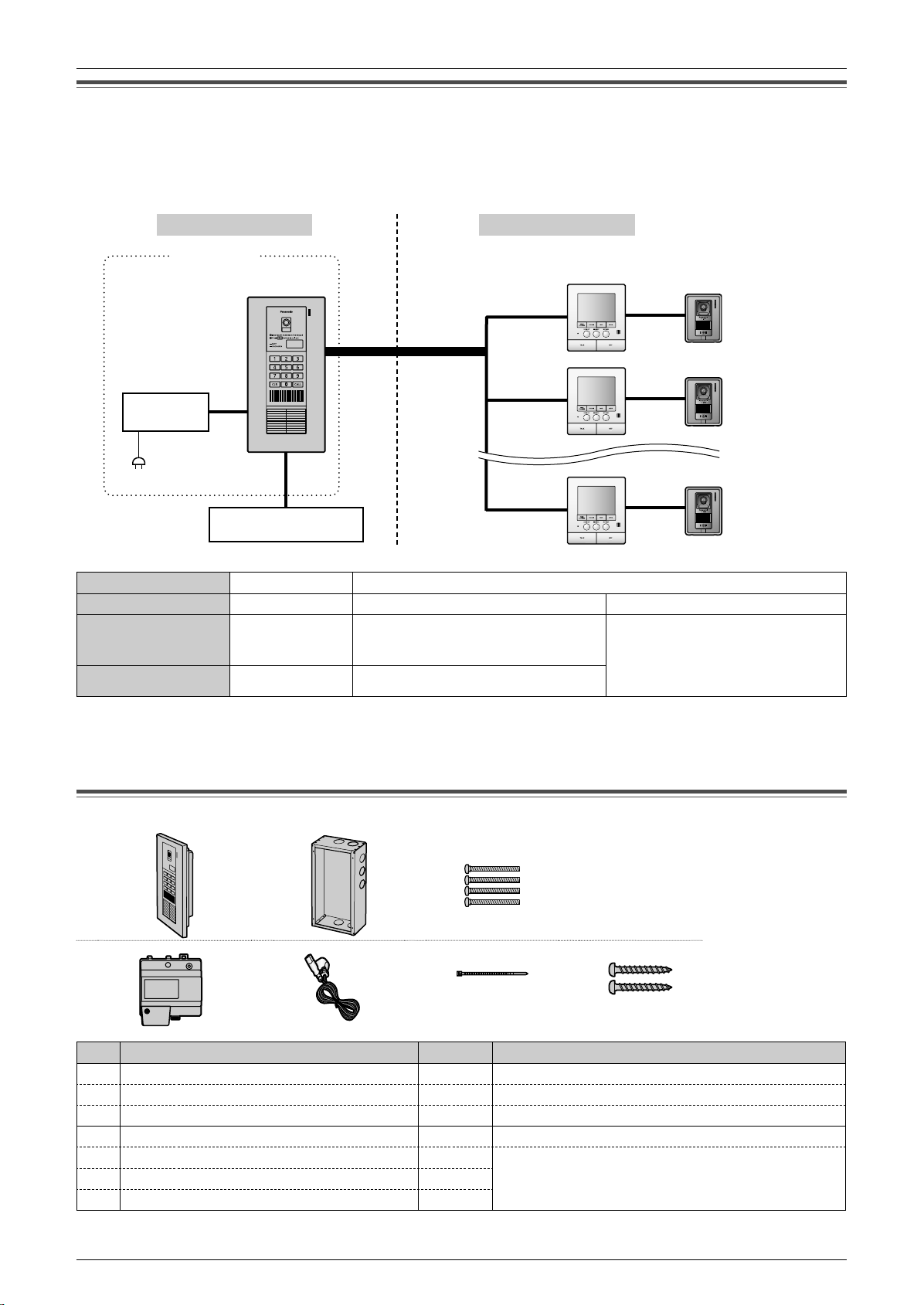
System component
The lobby station can be connected to up to 20 main monitor stations (in each room).
For details on the main monitor stations that are compatible to the lobby station, see the table below.
In this document, examples are shown with connections made to the VL-MW251 main monitor station. Depending on the
main monitor station used, operations may differ to those explained in this document. Please read the documentation of your
main monitor station.
Common entrance
Lobby station
Main unit
Max.
20 rooms
Power
supply unit
Power plug
(220 V – 240 V AC)
Door opener (Optional)
Resident
Main monitor station
Example: VL-MW251
Room
Room
Room
Door station
Example: VL-V566
N System component table (as of October, 2017)
Place
Unit name
Model no.
Connectable number
Note:
LFor details on optional units that can be connected to the main monitor stations, see the operating instructions of the main
monitor stations.
LIf units that are not specied in the table above are connected, the lobby station will not work properly.
LThe available products differ depending on your region. For more information, please consult your dealer.
Common entrance
Lobby station
VL-V591
1 20 (total)
Resident
Main monitor station (Main monitor)
VL-MW251, VL-MV30, VL-MV71,
VL-MV72, VL-MVN511, VL-MWD272,
VL-MWD273, VL-MW274, VL-MWD501
Door station
The types and number of door
stations that can be connected differs
depending on the main monitor used.
Refer to the documentation of your
main monitor station.
Included items
1 2
4 5 6 7
No. Item Quantity Notes
Main unit
1
Flush mounted box
2
Screw (4 mm x 25 mm)*
3
Power supply unit
4
AC cable
5
Cable binder*
6
Screw (4 mm x 40 mm)*
7
*1 Attached to the side of the main unit.
*2 Attached to the power supply unit.
2
1
2
3
1
1
4
1
1
Consists of the upper cabinet and lower cabinet (page 8).
------
For the ush mounted box
Model No. VL-PS241
For the power supply unit
1
2
2

Important Information
For your safety
To prevent severe injury and loss of life/property, read this section carefully before using the unit to ensure proper
and safe operation of your unit.
WARNING
Power connection
LUse only the power source marked on the unit. If you are not sure of the type of power supplied to the building,
consult your dealer or local power company.
LUse only the specied power supply unit.
LDo not place objects on the power cable. Install the unit where no one can step or trip on the cable.
LDo not overload power outlets and extension cords. This can result in the risk of re or electric shock.
LCompletely insert the power plug into the power outlet. Failure to do so may cause electric shock and/or
excessive heat resulting in a re.
LRegularly remove any dust, etc. from the power plug by pulling it from the power outlet, then wiping with a dry
cloth. Accumulated dust may cause an insulation defect from moisture, etc. resulting in a re.
LUnplug this unit from power outlets if it emits smoke, an abnormal smell or makes unusual noise. These
conditions can cause re or electric shock. Conrm that smoke has stopped and contact an authorized service
center.
LNever touch the plug with wet hands. Danger of electric shock exists.
LDo not connect a power cable to a terminal that is not specied in this guide. Connecting to the wrong terminal
may cause electric shock and/or excessive heat resulting in a re.
Installation
LLeave installation work to the dealer.
Installation work requires technique and experiences. Failure to observe this may cause re, electric
shock, injury, or damage to the product. Consult the dealer.
LElectrical connection work should be performed by certied personnel only.
Certication is required for performing electrical connection work. Consult your dealer.
LDo not install the product in a place where there is high humidity.
LDo not install the power supply unit in the following places:
– Places where the power supply unit may be splashed with water or chemicals.
– Places where there is a high concentration of dust, or high humidity.
LDo not allow the power cable or power plug to be excessively pulled, bent or placed under heavy objects.
LDo not make any wiring connections when the power supply is turned on.
LNever install wiring during a lightning storm.
LWhen existing wires are used, it is possible that they contain AC voltage. Electric shock or unit damage could
result. Contact an authorized service center.
Operating safeguards
LTo reduce the risk of electric shock, do not disassemble this unit. Refer servicing to an authorized service
center when service is required. Opening or removing covers may expose you to dangerous voltages or other
risks. Incorrect reassembly can cause electric shock when the unit is subsequently used.
LDo not touch the power supply unit/power plug during an electrical storm. There may be a remote risk of
electric shock from lightning.
LNever push any objects through slots in the power supply unit. This may result in the risk of re or electric
shock. Never spill any liquid on the power supply unit.
LUnplug this unit from power outlets and refer servicing to an authorized service center when the following
conditions occur:
A. If the power cable is damaged or frayed.
B. If metal objects have been dropped inside the unit.
C. If the power supply unit has been exposed to rain or water, or liquid has been spilled into the power supply
unit.
D. If the unit has been dropped or physically damaged.
3

Important Information
CAUTION
Installation and relocation
LThe power plug is used as the main disconnect device. Ensure that the power outlet is installed near the
product and is easily accessible.
LInstall the unit securely adhering to the instructions in this guide to prevent it from falling off the wall. Avoid
installing onto low-strength walls, such as gypsum board, ALC (autoclaved lightweight concrete), concrete
block, or veneer (less than 18 mm thick) walls.
Do not install the unit using a different method from the instructions in this guide.
LIf the wiring is outdoors, use a protection tube or a surge protector.
LIf the wiring is underground, do not make any connections underground.
LIf the wiring is underground, use a protection tube.
Important safety instructions
When using this unit, basic safety precautions should always be followed to reduce the risk of re, electric shock, or personal
injury.
L Use only the power cable indicated in this guide.
SAVE THESE INSTRUCTIONS
For best performance
Before using
LWhen power fails, this unit cannot be used.
Environment
LWhen you leave the unit unused for a long period of time, unplug it from the power outlet.
LThe power supply unit should be kept away from heat sources such as heaters, etc. It should not be placed in rooms where
the temperature is less than 0 °C or greater than 40 °C. Damp basements should also be avoided.
Other information
LPanasonic assumes no responsibility for injuries or property damage resulting from failures arising out of improper
installation or operation inconsistent with this documentation.
LIf you stop using the unit, remove the unit from the wall to prevent it from falling off.
LAfter the installation, explain all precautions and warnings to the customers before use.
LContact the dealer where you purchased this unit for repair.
Note for product disposal, transfer, or return
LThis product can save the PIN required to open the door. To protect your privacy/condentiality, we recommend that you
change the PIN to the default (0000) before you dispose of, transfer or return the product (page 14).
4
Controls
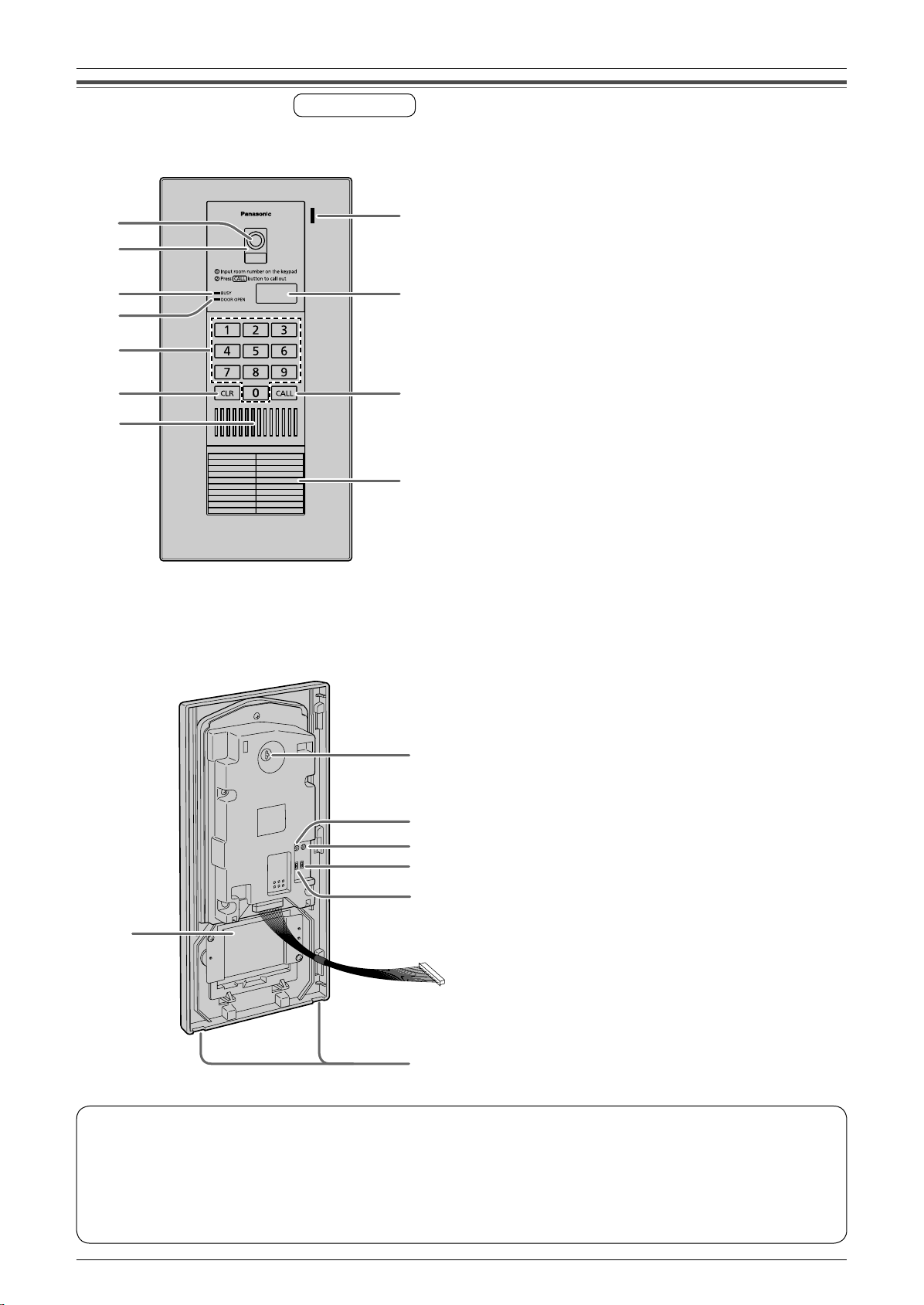
Location of controls
N Upper cabinet front view
A
B
C
D
E
F
G
Main unit
H
I
J
K
A Camera
B Lens cover
C BUSY indicator
LLights when the called main monitor station is in use.
D DOOR OPEN indicator
LLights when the door of the common entrance is
opened.
E Keypad
F {CLR} (CLEAR) button
LTo stop the operation.
G Speaker
H Microphone
I Room number display
J {CALL} button
LWhen a visitor presses the call button after entering the
room number, a ringer tone will ring.
N Upper cabinet rear view
LThe gure below shows the appearance when
the lower cabinet is removed (page 8).
L
M
N
O
P
Q
K Room number plate
LYou can write down room numbers on this plate by
removing the rear cover from the upper cabinet.
L Rear cover (for the room number plate)
M Camera angle control lever (page 8)
N PROGRAM switch
LTo register room numbers and program other settings
(page 12-14).
Use a pointed object such as a pen to press this switch.
O RESET switch
LTo reset the unit if it is not working properly.
(The program settings are not affected.)
Use a pointed object such as a pen to press this switch.
P BACKLIGHT COMPENSATION switch (page 9)
Q Speaker volume switch (page 9)
R Water drain holes
LThese holes allow rain water to drain.
Do not cover them.
R
N Lobby station image quality
The following phenomena may occur. They are not malfunctions.
L If the sun can be seen, its center appears as a black dot.
LAt night or when there is poor lighting in the doorway, the image colors become unclear. If there is a light in the
doorway, the image may appear greenish.
LDuring the daytime or if there is bright light in the doorway, the color of the visitor’s clothing may appear differently to
the actual color.
5
 Loading...