

Panasonic VL-SV74, VL-MV74, VL-V524 Installation Manual
Installation Guide
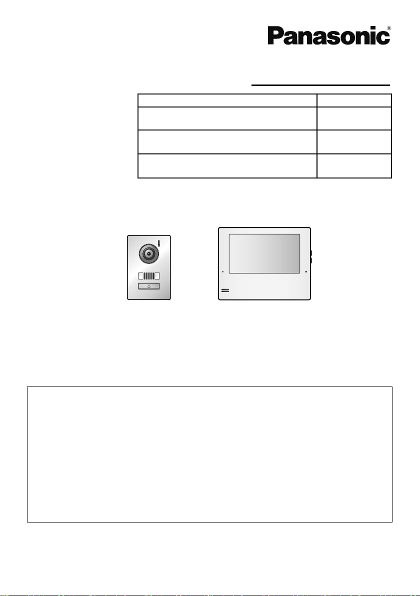
Model Name Model No.
VL-SV74
Video Intercom System
Main Monitor Station
R This guide is for use with the above 3 models.
Door station Main monitor station
R The Installation Guide in Indonesian and Thai can be accessed from the following site:
https://panasonic.net/cns/pcc/support/intercom/sv74
R Door station is described as "doorphone" and Main monitor station is described as "main
monitor" in this guide.
R In this guide, the suffix of each model number (e.g., the "BX" in "VL-SV74BX") is omitted
unless necessary.
Note to the installer
R Before attempting to connect or operate this product, please read the label on the rear of
the doorphone and the main monitor/extension monitor.
R Please read this guide carefully, and install the product safely and correctly by following
the instructions. Carefully read the information found in the section titled "For your
safety" in particular.
R Only use attachments/accessories specified by the manufacturer.
R The installation shall be carried out in accordance with all applicable installation rules.
R To the maximum extent permitted by law, Panasonic assumes no responsibility for
injuries or property damage resulting from failures arising out of improper installation
or operation inconsistent with this document.
R After installation, make sure to leave this guide with the customer.
VL-MV74
Door Station
VL-V524
R The VL-SV74 models composition consists of VL-MV74 and VL-V524.
VL-V524
VL-MV74
Model No.
For your safety
To prevent severe injury or loss of life or
property, and to ensure proper and safe
operation of your product, read this
section carefully before using the
product.
WARNING
Preventing fire, electric shock and
short circuits
R Leave installation work to the
dealer. Installation work requires
technique and experiences. Failure
to observe this may cause fire,
electric shock, injury, or damage to
the product. Consult the dealer.
RElectrical connection work should
be performed by certified personnel
only. Certification is required for
performing electrical connection
work. Consult your dealer.
RDo not attempt to disassemble or
modify this product. Contact an
authorised service centre for repairs.
RNever install wiring during a lightning
storm.
RDo not connect non-specified devices.
RDo not connect a power cable to a
terminal that is not specified in this
guide.
RWhen opening holes in walls for
installation or wiring, or when securing
the power cable, make sure you do not
damage existing wiring and ductwork.
RDo not make any wiring connections
when the power supply is turned on.
RDo not install the main monitor/
extension monitor in the following
places:
– Places where the main monitor/
extension monitor may be splashed
with water or chemicals.
– Places where there is a high
concentration of dust, or high
humidity.
RDo not place objects on the power
cables.
Install the product where no one can
step or trip on the power cables.
RDo not allow the power cables to be
excessively pulled, bent or placed
under heavy objects.
R When existing wires are used, it is
possible that they contain AC voltage.
Contact an authorised service centre.
CAUTION
Preventing electric shock
R If the wiring is underground, do not
make any connections underground.
RIf the wiring is underground, use a
protection tube.
R If the wiring is outdoors, use a
protection tube or a surge protector.
Preventing injury
R Install the product securely adhering to
the instructions in this guide to prevent
it from falling off the wall. Avoid
installing onto low-strength walls, such
as gypsum board, ALC (autoclaved
lightweight concrete), concrete block,
or veneer (less than 18
walls.
mm thick)
2
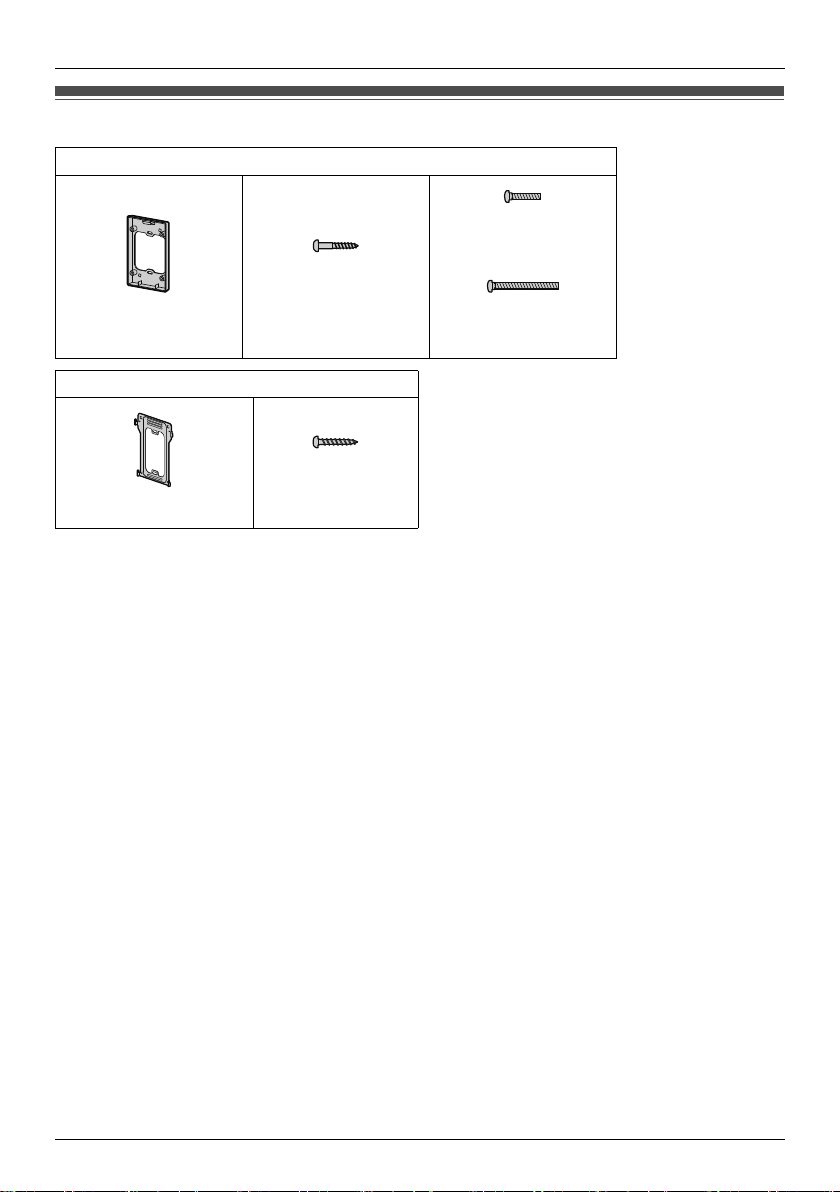
Supplied accessories for installation
For the doorphone
Screw × 4
Screw × 2
(3.8 mm × 20 mm)
Mounting base × 1
For the main monitor/extension monitor
Screw × 2
(4 mm × 16 mm)
Mounting bracket × 1
Important:
R You will need the following additional items to install and configure the doorphone and the
main monitor/extension monitor.
[Locally procured]
– Wires (for doorphone and other connections):
Prepare wires of the appropriate specification. (a"Wire type and length")
Note:
R The illustrations in the supplied manual(s) may vary slightly from the actual product.
*1 Used when using a separately sold flush mount box for installation.
(4 mm × 12 mm)
Screw × 4
(4 mm × 25 mm)
*1
3

Precautions for installation
To avoid malfunction or communication disturbances, do not install the doorphone or the main monitor/
extension monitor in the following locations:
– Places where vibration or any other kind of impact occurs.
– Places where echoing is frequent.
– Places near a high concentration of dust, hydrogen sulphide, ammonia, sulphur, or noxious fumes.
For the doorphone
R If a strong light is shining on the doorphone, the visitor’s face may not be distinguishable. Do not place
the doorphone in the following locations:
– Where most of the background is the sky.
– Where the background is a white wall, and direct sunlight will reflect off it.
– Where direct sunlight will shine on the doorphone.
R Do not place the doorphone in locations where echoing occurs, as this will cause the doorphone to
beep frequently.
R Dust protection/water protection is IP44.
Only when installation work specified in this guide is properly performed and appropriate water
protection treatment is performed.
R Make sure the rear of the doorphone is not subject to water.
R Depending on the installation location, condensation may form on the doorphone’s lens cover. This
may cause images to become obscured. Condensation will dissipate as the temperature rises.
For the main monitor/extension monitor
R Leave at least 20 cm of space above, below, and to the left and right sides of the main monitor/
extension monitor. Do not install on a wall that is deeply recessed.
R Do not install the main monitor/extension monitor inside a wall.
R Be sure to install the main monitor/extension monitor more than 5 m away from the doorphone.
R In areas surrounded by a high electrical field, disturbances may occur in the main monitor’s/extension
monitor’s image or sound.
Important:
R Do not use any cleaning products that contain alcohol, polish powder, powder soap, benzine, thinner,
wax, petroleum, or boiling water. Also do not spray the product with insecticide, glass cleaner, hair
spray or wall paint. This may cause a change in colour or quality of the product.
4
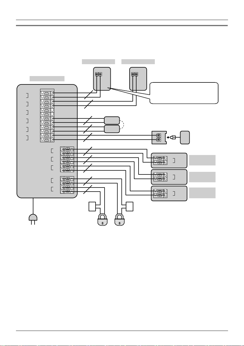
Wiring schematic diagram
Set up correctly according to the following wiring schematic diagram and "Wire type and length".
R For information, such as order numbers, about optional devices that can be connected to, refer to the
"Additional/replacement accessories" section in the Operating Instructions.
MAIN MONITOR
D1
1
D2
2
D3
3
D4
4
Ml-1
5
Ml-2
6
IN1
7
IN2
8
IN3
9
IN4
10
P1
11
P2
12
MO-1
MO-2
MO-3
MO-4
MO-5
MO-6
S1
S2
S3
S4
13
14
15
16
17
18
19
20
21
22
DOORPHONE 1 DOORPHONE 2
NP
NP
NP
NP
NP
NP
NP
NP
NP
NP
AA
*1
Connection device
for option Input
(A contact)
*2
*1
You can also connect an
optional lobby station. (See
page 7.)
PBX
Terminal box
(4-conductor
wiring)
EXTENSION
Ml-1
5
Ml-2
6
5
6
5
6
Ml-1
Ml-2
Ml-1
Ml-2
MONITOR 1
EXTENSION
MONITOR 2
EXTENSION
MONITOR 3
Power plug
(220-240 V AC)
Electric
lock
Electric
lock
NP: Non-polarised
A Power supply
*1 When you use an additional doorphone, the maximum number of the electric locks that can be
connected to the doorphone depends on the type of doorphone. Consult your dealer for further
information.
For VL-V554 users:
– The electric lock can also be connected to the S1/S2 terminals of the doorphone.
*2 Connection devices for option input (A contact).
– Make sure to connect doorbells to the IN3/IN4 terminals. A doorbell and doorphone 2 cannot be
used together.
– When a VL-V901 and VL-V700 series Video Intercom System for Apartment Complexes is used,
emergency terminals can be used. Make sure to connect emergency terminals to the IN1/IN2
terminals.
5
 Loading...