

Panasonic VL-SWH705, VL-SVH705 Quick Reference Manual
Quick Reference Guide
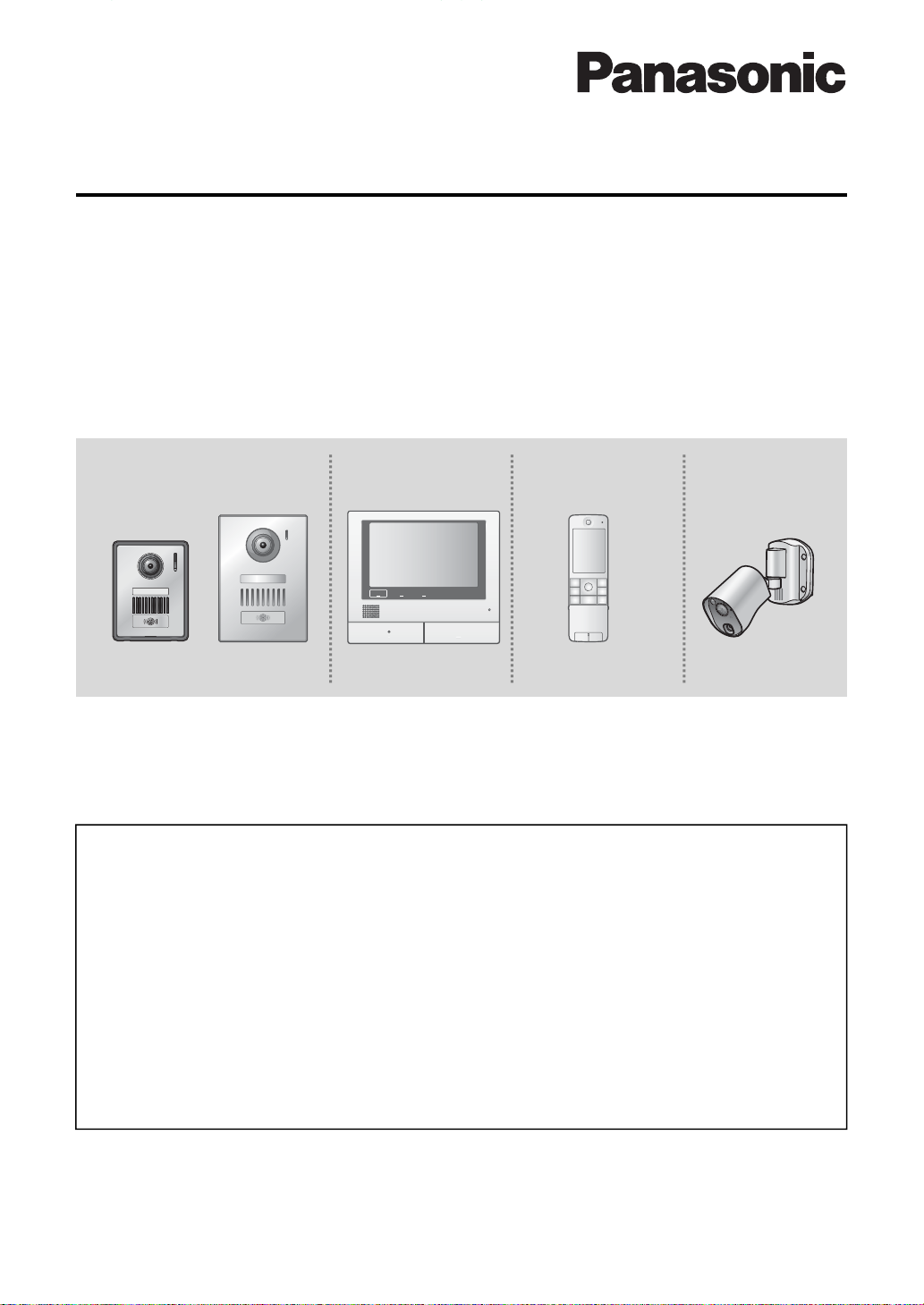
Wireless Video Intercom System
Model No.
VL-SWH705 series
Video Intercom System with Wireless Sensor Camera/
Video Intercom System
Model No.
Door Station
(Doorphone)
①VL-VH573*
*1 It is the Part No. printed on the unit.
Model composition
●VL-SWH705KL(① + ③ + ④) ●VL-SWH705KS(② + ③ + ④)
●VL-SVH705KLC(① + ③ + ⑤) ●VL- 705KSC(② + ③ + ⑤)
●VL-SVH705KL (① + ③) ●VL- 705KS (② + ③)
1
②VL-VH556*
Main Monitor Station
(Main monitor)
1
③VL-MWH705*
Sub Monitor Station
(Sub monitor)
1
④VL-WD616*
VL-SVH705 series
Wireless Sensor
Camera (Camera)
1
⑤VL-WD813*
1
Table of Contents
Door Station (Doorphone)
Parts Descriptions ........................................................................................................ ...... ...2
Wireless Sensor Camera (Camera)
Parts Descriptions ........................................................................................................ ...... ...3
Main Monitor Station (Main monitor)
Parts Descriptions ........................................................................................................ ...... ...4
Basic Operations ................................................................................................ .............. .....5
Sub Monitor Station (Sub monitor)
Parts Descriptions ........................................................................................................ ...... ...6
Basic Operations ................................................................................................ .............. .....7
Thank you for purchasing a Panasonic produ ct.
● This guide explains some basic features and operations, but not all of them. For further details,
see the Japanese operating instructions.
● This product is designed for use in Japan.
Panasonic cannot provide service for this product if used outside Japan.
● Any details given in this guide are subject to change without notice.
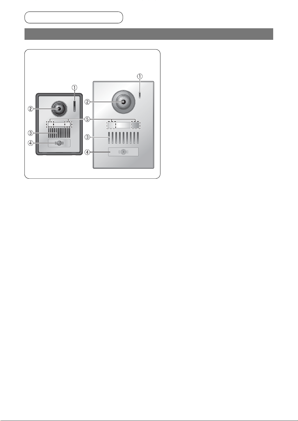
Door Station (Doorphone)
Door Station (Doorphone)
Parts Descriptions
■ VL-VH573
■ VL-VH556
①Microphone
②Camera lens
③Speaker
④Call button & indicator (red)
⑤LED lights
2
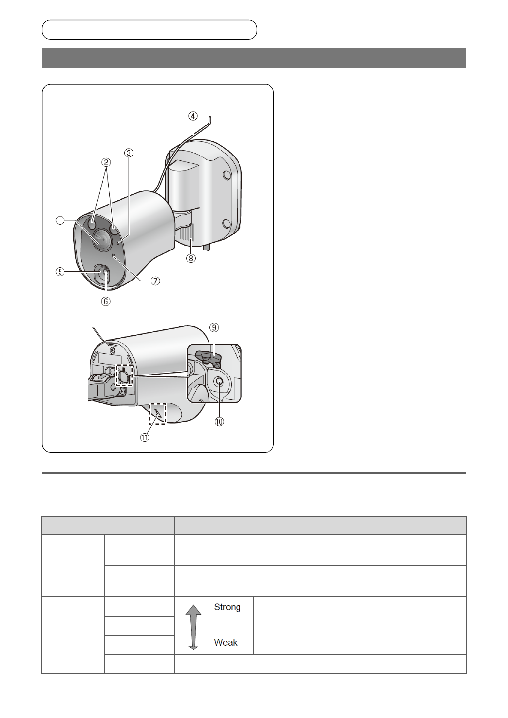
Wireless Sensor Camera (Camera)
Parts Descriptions
Wireless Sensor Camera (Camera)
■ VL-WD813
〈Rear view 〉
①Lens cover & Lens(inside the
cover)
②LED lights
③Indicator lamp (See the following
explanation.)
④Safety wire
⑤Sensor range cap (standard type)
4 types of lens caps (accessories)
can be fitted as required. (See the
Camera’s Installation Guide.)
⑥Heat sensor
Detects changes in temperature.
⑦Microphone
⑧Speaker
⑨Register button cover
⑩Register button (behind the
register button cover)
Used when registering the camera
to the main monitor. (In case of VLSVH705KLC & VL-SVH705KSC, the
camera has already been registered
in the main monitor.)
⑪Heat sensor lever
Used to change the angle of the
heat sensor. (See the Camera’s
Installation Guide.)
Indicator lamp
After the camera has been registered to the main monitor, you can check the camera’s status and
the wireless signal status from the main monitor by checking the status of the indicator lamp.
Indicator display Camera’s status
Transmission
status
Signal status
(during
standby)
Flashing green
(fast)
Flashing green
(slow)
Lit green
Lit orange
Lit red
Flashing red Transmissions cannot be sent because there is no signal (out of range).
A sensor has been triggered and the camera is calling the main monitor.
The camera is transmitting data to the main monitor.
Indicates the signal status from the main monitor.
● We recommend installing the camera in an area
where the status indicator is strong (when the
indicator is lit green).
3
 Loading...