

Panasonic VL-V900, VL-MVN511, VL-MV26, VL-MW251 User Manual
Key Features
VL-V900
VL-MVN511 VL-MW251
Supports large apartment systems
3 lobby stations and 560 room monitors are supported for a building. When connected to a PBX system (for instance, the Panasonic KX-TES824 system),
4 guard stations and multiple buildings are supported.
Provides safety and security to residents
1) Answer visitors after checking their face. Check visitors using a smartphone (VL-MNV511 only) or the wireless monitor (VL-MW251 only).
2) Record the image of visitors and check them at any time.
3) Monitor common surveillance cameras from your own room.
4) Notify of accidents (fire, injury, etc.) to reception, another station via a PBX.
Easy and low cost installation
The system mainly needs only 2 wire cables (1 pair of cables), and less equipment. It provides an easy way to link up rooms in one location using a PC,
and can also be set up with a room monitor in every room.
Safe and convenient maintenance functions
The system provides a self-diagnostic function to identify errors. It is easy to change the equipment and re-link. Log function for recording the face of
visitors and the date.
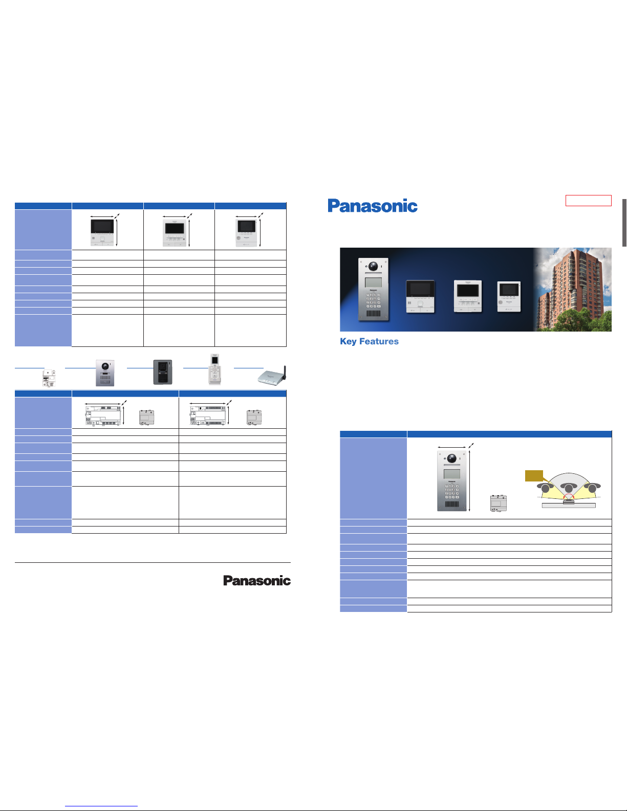
Model number and n ame VL-V900 (Lobby S tation)
Dimensions
(mm)
Power supply
T.B.D. (Attache d power supply unit is AC 220 -240 V)
Power consumption
Standby: Appr ox. T.B.D. / During operation: A pprox. T.B.D.
Dimensions (H x W x D)
(Excluding pro truding sections)
373 x 179 x 2.5 mm (excluding secti ons embedded into the wall)
Flush mounting only
Weight
2.0 kg
Operating envir onment
-10 °C to 50 °C, Up to 90 % RH (R elative Humidity) non co ndensing
IP rating/I K rating
IP55 / IK07
Viewing angle
Horizontally: A pprox. 170˚, Vertically: A pprox. 115˚
Expanded inte rface
Support for elec tric lock releasing (ent rance unlocking) x 1 / VID EO-IN (recommende d Panasonic CCT V) x 1
Supported fu nctions
Guidance (simple usag e for visitors)
Night colour vision ( white LED installed )
Human sensor: Mo nitor power is turned on whe n a person approaches.
Display the residen t’s names
Installation m ethod
Flush mounted on wall / s pecial board
External ma terial
Aluminium / stainles s steel
Model number and n ame VL-MVN511 (Main Monit or) VL-MW251 (Main M onitor) VL-MV26 (Main Mo nitor)
Dimensions
(mm)
Power supply
T.B.D.
(Attached p ower supply unit is AC 220 -240 V)
100-240 V AC (50- 60Hz) T.B.D.
(Attached p ower supply unit is AC 220 -240 V)
Power consumption
Standby: T.B.D. / Duri ng operation: T.B.D. Standby: 0.04 A / During operation: 0. 28A Standby: T.B.D. / During opera tion: T.B.D.
Display
Approx. 5 inch / WQV GA Approx. 5 inch, wide / W QVGA Approx. 3.5 inch, w ide / QVGA
Dimensions (H x W x D)
(Excluding pro truding sections)
186 x 161 x 23.5 mm 190 x 165 x 38 mm 169 x 129 x 29 mm
Weight
500 g 785 g 345 g
PTZ
Pan, Tilt, Zoom ( for VL-V900, VL-V555) Pan, T ilt, Zoom (for VL-V900, V L-V555) -
Recording
8 images x 50 calls 1 image x 100 ca lls or 8 images x 50 calls 1 image x 30 calls
Wireless
Wi-Fi (IE EE802.11 b/g/n 2.4GHz) 2.4 G Hz FHSS -
Function
•1 door s tation input / 1 door be ll input
•E-L ock release (both i ndividual
*
and public)
•Guar d call
•Moni tor CCTV
•Smar tphone Connect vi a Wi-Fi local net work
(Smartphone a pplication is availab le for free)
•Send ma il via the Internet (w ith visitor’s image)
•Emerg ency call
•1 door s tation input
•E-L ock release (both i ndividual and public)
•Guar d call
•Moni tor CCTV
•Wirel ess sub monitor availa ble (VL-W605)
•Voice ch ange function:
make woman’s voice sound l ike a man’s
•Pagin g: transfer calling (w ireless sub monitor s)
•1 door b ell input
•E-L ock release (public)
•Guar d call
•Moni tor CCTV
*
A Lift Controller (VL-V702) will be provided. By using this controller, it is possible to synchronize the lift stop floor with the unlock control in the system.
*
The optional VL-RLY1 is required to open individual E-locks.
Trademarks and r egistered tr ademarks
- SD, SDHC, SDXC, and SDXC Logo are trade marks of SD-3C, LLC.
- Wi-Fi is a tradema rk or registered t rademark of Wi-Fi A lliance.
Important
- Safety Precau tion: carefully r ead the operating i nstructions a nd installation ma nual before using t his product.
VL-V900 series
Video Intercom System
(for apartment, condominium)
Specifications
Options:
VL-V555
Door Station
(Aluminium surface)
(for VL-MVN511)
VL-V522L
Door Station
(Resin surface)
(for VL-MVN511,
VL-MW251)
VL-W605
Sub Monitor
(for VL-MW251)
up to 4
VL-RLY1
Relay Box
(for VL-MVN511)
VL-FAN1
Repeater
(for VL-MW251)
up to 2
Power
Supply
Unit
VL-MV26
MG-DHPE002EN 1506ITP/TD-1
169
129
29
190
165
38
186
161
23.5
373
179
2.5
Model number and n ame VL-V700 (Control Box) VL-V701 (Distr ibution Box/Repeat er Box)
Dimensions
(mm)
Power supply
T.B.D. (Attache d power supply unit is AC 220 -240 V) T.B.D. (Attache d power supply unit is AC 220 -240 V)
Power consumption
Standby: Appr ox. T.B.D. / During operation: A pprox. T.B.D. St andby: Approx. T.B.D. / During o peration: Approx. T.B. D.
Dimensions (H x W x D)
(Excluding pro truding sections)
108.5 x 210 x 52.5 mm 108.5 x 210 x 52.5 mm
Weight
400 g 400 g
Operating envir onment
Ambient temperat ure:
0 °C to 40 °C, Up to 90 % R H (Relative Humidit y) non condensing
Ambient temperat ure:
0 °C to 40 °C, Up to 90 % R H (Relative Humidit y) non condensing
Log
Save the text logs an d visitors’ images in the SD C ard (sold separately )
Text logs: More than 9 0,000 items
Images: Up to 90,0 00 images
-
Supported fu nctions
USB connectio n (provide PC applicat ion / English)
•date an d time setting (H H: MM DD/MM/ YYY Y)
•set th e room number with the mo nitor
•esti mate the status of th e equipment in the system
•oper ation setting ( TERMIN AL, pass code, and s o on.)
SD Card (SD/S DHC/SDXC): Lo g function
VIDEO OUT PUT (NTS C/PAL up to 1)
RJ-11: PBX SLT function (connect w ith PBX system to guar d stations)
Dip switch
•Mode c hange (Distribut or/Repeater)
•Terminati on setting (Nor mal/Terminal)
•ID set ting (1-7 by binary number)
Installation m ethod
Wall implanted (or can be in stalled on DIN rail) Wall implanted (or can be in stalled on DIN rail)
External ma terial
Flame retardan t ABS resin Flame retardan t ABS resin
Power
Supply
Unit
Power
Supply
Unit
108.5
210
52.5
108.5
210
52.5
• The actual product may vary slightly from photograph.
• All pictures of the LCD display are simulated.
• Weights and dimensions are approximate.
• Design and Specications are subject to change without notice.
• These products may be subject to export control regulations.
Super wide view.
Horizon
170˚
Standard
90˚
Preliminary
DISTRIBUTED BY :
Power
Supply Unit
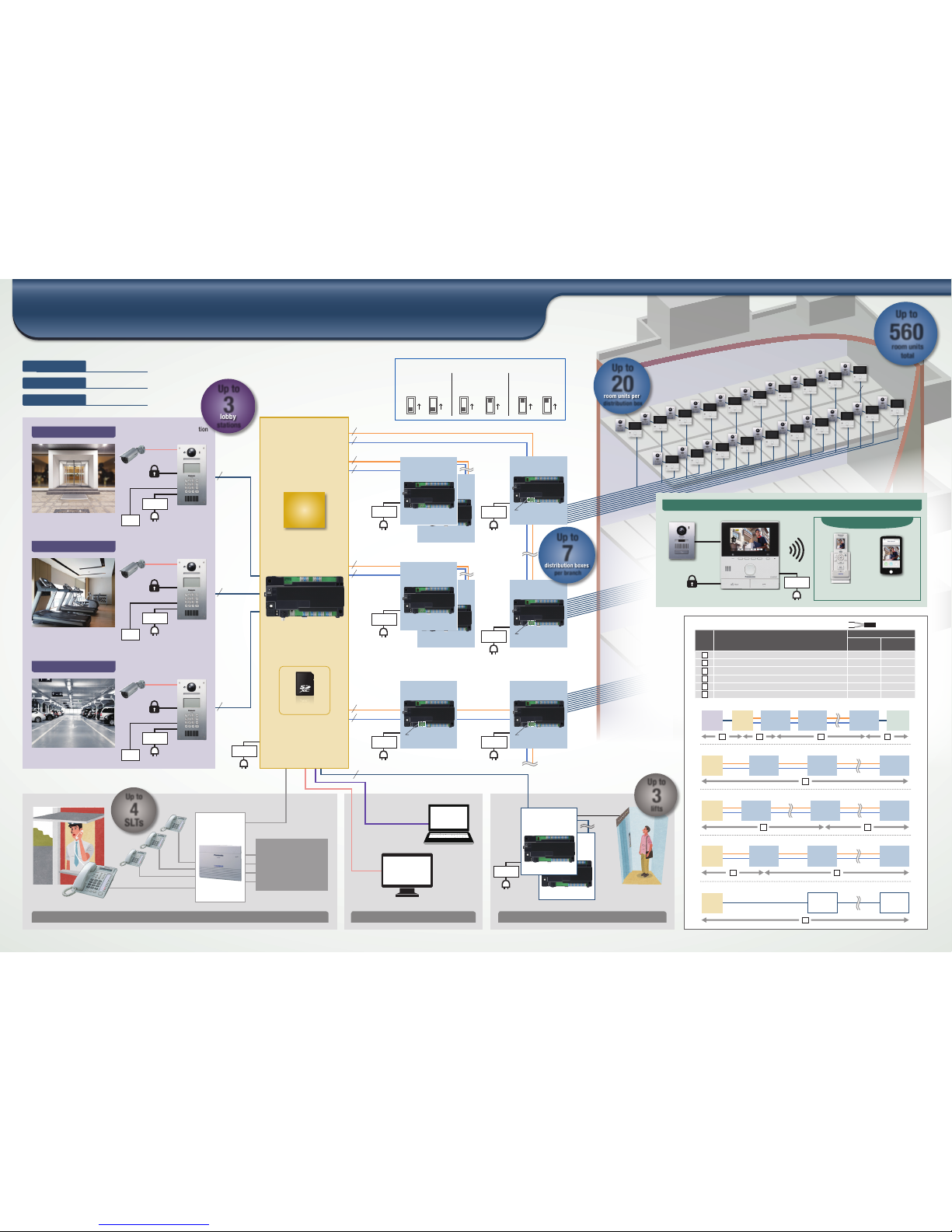
System Diagram of the Apartment System
Entrance
Room
Expandable options
Common Area
Parking
Guard Station Security Control Room
Distributio n Box
VL-V701
Lobby Station
VL-V900
Control Box
VL-V700
Distributio n Box
VL-V701
Standard Mod e
*1
(STD/NOR)
Standard Mod e
*2
(STD/END)
#7
(Up to 7)
Repeater Mode
*3
(RPT/END)
Wireless Moni tor
(for VL-MW251)
Door Station
Free applicat ion for
smartphone s upport
(for VL-MVN511)
Main Monitor
room units
total
Up to
560
distributi on boxes
per branch
Up to
7
room units per
distributi on box
Up to
20
Total System
1 unit
28 units
560 units
Control Box
Distribution Box
Main Monitor
Lobby
Station
Control
Box
Control
Box
Control
Box
Control
Box
Control
Box
Main
Monitor
Distributi on
Box
(STD
*2
)
Lift
Controller
Distributi on
Box
(STD
*2
)
Distributi on
Box
(STD
*1
)
Distributi on
Box
(RPT
*3
)
Distributi on
Box
(STD
*2
)
Distributi on
Box
(RPT
*3
)
Distributi on
Box
(STD
*1
)
Distributi on
Box
(STD
*2
)
Distributi on
Box
(STD
*1
)
Distributi on
Box
(STD
*1
)
Lift
Controller
Distributi on
Box
(STD
*1
)
#1
#1
#1
#1
#1
#2
Distributi on
Box
(RPT
*3
)
SD Card*
(sold separately)
Wiring Distance
No Wiring run
Wire diamete r
0.65 mm
(22 AWG)
1.2 mm
(17 AWG)
Control Box - Lo bby Station 100 m 200 m
Control Box - Dis tribution Box (St andard Mode
*2
) 100 m 20 0 m
Distribution B ox (Standard Mode
*1*2
) - Main Monitor 100 m 200 m
Control Box - Dis tribution Box (Rep eater Mode
*3
) 100 m 200 m
Distribution B ox (Repeater Mode*3) - Distribution B ox (Standard Mode*2)
100 m 20 0 m
Control Box - the f arthest Lift C ontroller 100 m 200 m
VL-V701 Dip switch
REPEATE R REPEATER REPE ATERTERMIN ATION TER MINATION T ERMINAT ION
ON ON ONON ON ON
*1 Standard M ode
(STD/NOR )
*2 Stan dard Mode
(STD /EN D)
*3 Repeater Mod e
(RPT/END)
4 5
54
6
2
1
1
2
3
4
5
6
4 5 3
You can extend the distance
by using the repeater mode.
* 4 GB or more capacities
are required.
#1
#1
#1
#1
#1
*
Use PE (polyethylene)-insulated cables.
#5 (Up to 5)
Lift
(Up to 100 floor s)
Power
Supply Unit
lifts
Up to
3
Distributio n Box
VL-V701
Distributio n Box
VL-V701
Distributio n Box
VL-V701
Lift Contr oller
VL-V702
#5
(Up to 5)
Access
control
Access
control
USB
Coax
(NTSC/ PAL)
PBX Line
Monitor
PC
(Setting)
PBX System
Security
Camera
Coax
Coax
Coax
(NTSC/PA L)
(NTSC/PA L)
(NTSC/PA L)
E-Lock2
#7 (Up to 7)
#7 (Up to 7)
#7 (Up to 7)
#7 (Up to 7)
lobby
stations
Up to
3
SLTs
Up to
4
Connect to
multiple buildings
through the PBX
system
VIDEO 2 Wire, N P
2 Wire, NP
2 Wire, NP
VIDEO 2 Wire, N P
VIDEO 2 Wire, N P
VIDEO 2 Wire, N P
AUDIO 2 Wire, N P
AUDIO 2 Wire, N P
AUDIO 2 Wire, N P
AUDIO 2 Wire, N P
2 Wire, NP
2 Wire, NP
Branches
4
2 Wire, NP
2 Wire, NP
Distributio n Box
VL-V701
Standard Mod e
*1
(STD/NOR)
Lobby Station
VL-V900
Lobby Station
VL-V900
Security
Camera
Security
Camera
E-Lock1
E-Lock1
E-Lock1
Power
Supply Unit
Access
control
Power
Supply Unit
Power
Supply Unit
Power
Supply Unit
Power
Supply Unit
Power
Supply Unit
Power
Supply Unit
Power
Supply Unit
Power
Supply Unit
Power
Supply Unit
#7
(Up to 7)
#7
(Up to 7)
 Loading...