

Panasonic TH-50PM50U, Viera TH-42PM50, Viera TH-50PM50, TH42PM50 - 42"" PLASMA -NO TUNE, TH50PM50 - 50"" PLASMA - NO TUNE Operating Instructions Manual

Operating Instructions
OK
Progressive Wide Plasma Display
Model No.
TH-42PM50U
High Defi nition Plasma Display
Model No.
TH-50PM50U
For assistance, please call : 1-888-VIEW-PTV (843-9788)
or visit us at www.panasonic.com/contactinfo (U.S.A.)
For assistance, please call : 787-750-4300
or visit us at www.panasonic.com (Puerto Rico)
Before connecting, operating or adjusting this product, please read these instructions completely.
Please keep this manual for future reference.
English
TQB2AA0591
The lightning flash with
arrow-head within a triangle
CAUTION
RISK OF ELECTRIC SHOCK
DO NOT OPEN
WARNING: To reduce the risk of electric shock, do not remove cover or back. No
user-serviceable parts inside. Refer servicing to qualifi ed service personnel.
is intended to tell the user
that parts inside the product
are a risk of electric shock
to persons.
The exclamation point
within a triangle is intended
to tell the user that important
operating and servicing
instructions are in the
papers with the appliance.
WARNING : To reduce the risk of fire or electric shock, do not expose this apparatus to rain or
moisture.
Do not place liquid containers (flower vase, cups, cosmetics, etc.) above the set
(including on shelves above, etc.).
WARNING
2) Do not remove the grounding pin on the power plug. This apparatus is equipped with a three pin
Do not defeat the purpose of the grounding plug.
Note : Do not allow a still picture to be displayed for an extended period, as this can cause a permanent
afterimage to remain on the Plasma Display.
Examples of still pictures include logos, video games, computer images, teletext and images displayed in 4:3
mode.
1) To prevent electric shock, do not remove cover. No user serviceable parts inside. Refer servicing
to qualifi ed service personnel.
grounding-type power plug. This plug will only fi t a grounding-type power outlet. This is a safety
feature. If you are unable to insert the plug into the outlet, contact an electrician.
HDMI, the HDMI logo and High-Definition Multimedia Interface are trademarks or registered
trademarks of HDMI Licensing LLC.
2
Important Safety Instructions
1) Read these instructions.
2) Keep these instructions.
3) Heed all warnings.
4) Follow all instructions.
5) Do not use this apparatus near water.
6) Clean only with dry cloth.
7) Do not block any ventilation openings. Install in
accordance with the manufacturer’s instructions.
8) Do not install near any heat sources such as
radiators, heat registers, stoves, or other apparatus
(including amplifi ers) that produce heat.
9) Do not defeat the safety purpose of the polarized or
grounding-type plug. A polarized plug has two blades
with one wider than the other. A grounding type plug
has two blades and a third grounding prong. The wide
blade or the third prong are provided for your safety. If
the provided plug does not fi t into your outlet, consult
an electrician for replacement of the obsolete outlet.
10)
Protect the power cord from being walked on or
pinched particularly at plugs, convenience receptacles,
and the point where they exit from the apparatus.
FCC STATEMENT
11) Only use attachments / accessories specifi ed by the
manufacturer.
12) Use only with the cart, stand,
tripod, bracket, or table specified
by the manufacturer, or sold with
the apparatus. When a cart is
used, use caution when moving
the cart / apparatus combination to
avoid injury from tip-over.
13) Unplug this apparatus during lightning storms or when
unused for long periods of time.
14) Refer all servicing to qualified service personnel.
Servicing is required when the apparatus has been
damaged in any way, such as power-supply cord or
plug is damaged, liquid has been spilled or objects
have fallen into the apparatus, the apparatus has
been exposed to rain or moisture, does not operate
normally, or has been dropped.
15) To prevent electric shock, ensure the grounding pin
on the AC cord power plug is securely connected.
FCC STATEMENT
This equipment has been tested and found to comply with the limits for an Other Class B digital device, pursuant to
Part 15 of the FCC Rules. These limits are designed to provide reasonable protection against harmful interference in
a residential installation. This equipment generates, uses and can radiate radio frequency energy and, if not installed
and used in accordance with the instructions, may cause harmful interference to radio communications. However,
there is no guarantee that interference will not occur in a particular installation. If this equipment does cause harmful
interference to radio or television reception, which can be determined by turning the equipment off and on, the user
is encouraged to try to correct the interference by one of the following measures:
• Reorient or relocate the receiving antenna.
• Increase the separation between the equipment and receiver.
• Connect the equipment into an outlet on a circuit different from that to which the receiver is connected.
• Consult the Panasonic Service Center or an experienced radio/TV technician for help.
FCC Caution:
To assure continued compliance, use only shielded interface cables when connecting display to peripheral
devices.
Any changes or modifi cations not expressly approved by responsible party may cause harmful interference
and could void the user's authority to operate this device.
Responsible Party : Panasonic Corporation of North America
One Panasonic Way, Secaucus, NJ 07094
Contact Source : Panasonic Consumer Electronics Company
1-888-VIEW-PTV (843-9788)
email : consumerproducts@panasonic.com
3

Dear Panasonic Customer
Welcome to the Panasonic family of customers. We hope that you will have many years of enjoyment from
your new Plasma Display.
To obtain maximum benefi t from your set, please read these Instructions before making any adjustments,
and retain them for future reference.
Retain your purchase receipt also, and record the model number and serial number of your set in the
space provided on the back cover of these instructions.
Visit our Panasonic Web Site: www.panasonic.com
For assistance, please call : 1-888-VIEW-PTV (843-9788)
or visit us at www.panasonic.com/contactinfo (U.S.A.)
For assistance, please call : 787-750-4300
or visit us at www.panasonic.com (Puerto Rico)
Table of Contents
Important Safety Instructions ..................................3
FCC STATEMENT ...................................................... 3
Safety Precautions ................................................... 5
Cleaning and maintenance ...................................... 6
Accessories .............................................................. 6
Installation .................................................................7
Location ...................................................................7
Optional External Equipment .................................. 7
Remote Control Battery Installation ......................... 7
Cable Connection ..................................................... 8
HDMI Connection .................................................... 9
Digital TV Set-Top Box (DTV-STB) or
DVD Connection .................................................... 10
Video Input Connection ......................................... 10
Amplifi er Connection ............................................. 11
Program Out Connection (PROG OUT) ................ 11
Basic Controls ........................................................ 12
Power ON / OFF ...................................................... 13
The Main Unit ........................................................ 13
Initial Selections ..................................................... 14
Selecting the input signal ......................................14
Selecting the Language ......................................... 14
On-Screen Menu Displays for Navigation ............ 15
Aspect Controls ...................................................... 16
Menu Navigation ..................................................... 17
Picture ...................................................................17
Audio .....................................................................19
Setup .....................................................................20
VIDEO/COMPONENT/HDMI input signals ............. 21
Specifi cations .........................................................21
Troubleshooting .....................................................22
CUSTOMER SERVICES DIRECTORY
(for U.S.A.) ............................................................... 23
Limited Warranty (for U.S.A.)
................................. 24
4

Safety Precautions
WARNING
SMALL PARTS CAN PRESENT CHOKING HAZARD IF
ACCIDENTALLY SWALLOWED.
KEEP SMALL PARTS AWAY FROM YOUNG CHILDREN.
DISCARD UNNEEDED SMALL PARTS AND OTHER
OBJECTS, INCLUDING PACKAGING MATERIALS AND
PLASTIC BAGS/SHEETS TO PREVENT THEM FROM
BEING PLA YED WITH BY YOUNG CHILDREN, CREA TING
THE POTENTIAL RISK OF SUFFOCATION.
Set up
Do not place the Plasma Display on sloped or unstable
surfaces.
• The Plasma Display may fall off or tip over.
Do not place any objects on top of the Plasma
Display.
• If water spills onto the Plasma Display or foreign objects
get inside it, a short-circuit may occur which could
result in fi re or electric shock. If any foreign objects get
inside the Plasma Display , please consult an Authorized
Service Center.
Do not cover the ventilation holes.
• Doing so may cause the Plasma Display to overheat,
which can cause fire or damage to the Plasma
Display.
If using the pedestal, leave a space of 3 15/16” (10 cm)
or more at the top, left and right, 2 3/8” (6 cm) or more
at the bottom, and 2 3/4” (7 cm) or more at the rear. If
using some other setting-up method, leave a space of
3 15/16” (10 cm) or more at the top, bottom, left and
right, and 3/4” (1.9 cm) or more at the rear.
Avoid installing this product near electronic equipment
that is readily affected by electromagnetic waves.
• It may cause interference in image, sound, etc. In
particular, keep video equipment away from this
product.
AC Power Supply Cord
The Plasma Display is designed to operate on 120 V
AC, 50/60 Hz.
Securely insert the power cord plug as far as it will go.
• If the plug is not fully inserted, heat may be generated
which could cause fi re. If the plug is damaged or the
wall socket plate is loose, they should not be used.
Do not handle the power cord plug with wet hands.
• Doing so may cause electric shocks.
Do not do anything that might damage the power cable.
When disconnecting the power cable, hold the plug,
not the cable.
• Do not make any modifi cations to, place heavy objects
on, place near hot objects, heat, bend, twist or forcefully
pull the power cable. Doing so may cause damage to
the power cable which can cause fi re or electric shock.
If damage to the cable is suspected, have it repaired at
an Authorized Service Center.
If the Plasma Display will not be used for a long period
of time, unplug the power cord from the wall outlet.
If problems occur during use
If a problem occurs (such as no picture or no sound),
or if smoke or an abnormal odor is detected from the
Plasma Display, unplug the power cord immediately.
Continued use of the Display under these conditions might
•
cause fi re or permanent damage to the unit. Have the
Display evaluated at an Authorized Service Center . Servicing
of the Display by any unauthorized personnel is strongly
discouraged due to its high voltage dangerous nature.
If water or foreign objects get inside the Plasma Display , if
the Plasma Display is dropped, or if the cabinet becomes
damaged, disconnect the power cord plug immediately.
• A short may occur, which could cause fi re. Contact an
Authorized Service Center for any repairs that need to
be made.
CAUTION
This Plasma Display is for use only with the following
optional accessories. Use with any other type of
optional accessories may cause instability which could
result in the possibility of injury.
(All of the following accessories are manufactured by
Matsushita Electric Industrial Co., Ltd.)
• Pedestal (included)
TY-ST42PX5W (TH-42PM50U)
TY-ST50PX5W (TH-50PM50U)
• Wall-hanging bracket (Vertical) TY-WK42PV3U
• Wall-hanging bracket (Angled) TY-WK42PR2U
Always be sure to ask a qualifi ed technician to carry out set-up.
When using the Plasma Display
Do not bring your hands, face or objects close to the
ventilation holes of the Plasma Display.
• Top of the Plasma Display is usually very hot due to the
high temperature of exhaust air being released through
the ventilation holes. Burns or personal injuries can
happen if any body parts are brought too close. Placing
any object near the top of the Display could also result
in heat damage to the object as well as to the Display
if its ventilation holes are blocked.
Be sure to disconnect all cables before moving the
Plasma Display.
• Moving the Display with its cables attached might
damage the cables which, in turn, can cause fi re or
electric shock.
Disconnect the power plug from the wall outlet as a
safety precaution before carrying out any cleaning.
• Electric shocks can result if this is not done.
Clean the power cable regularly to prevent it from
becoming dusty.
Built-up dust on the power cord plug can increase humidity
•
which might damage the insulation and cause fi re. Unplug
the cord from the wall outlet and clean it with a dry cloth.
This Plasma Display radiates infrared rays; therefore, it
may affect other infrared communication equipment.
Install your infrared sensor in a place away from direct
or refl ected light from your Plasma Display.
Note:
Do not allow a still picture to be displayed for an extended
period, as this can cause a permanent after-image to remain
on the Plasma Display.
Examples of still pictures include logos, video games, computer
images, teletext and images displayed in 4:3 mode.
5
6
Cleaning and maintenance
The front of the display panel has been specially
treated. Wipe the panel surface gently using only a
cleaning cloth or a soft, lint-free cloth.
• If the surface is particularly dirty, soak a soft, lint-free
cloth in a weak detergent solution and then wring the
cloth to remove excess liquid. Use this cloth to wipe the
surface of the display panel, then wipe it evenly with a
dry cloth, of the same type, until the surface is dry.
• Do not scratch or hit the surface of the panel with
fi ngernails or other hard objects. Furthermore, avoid
contact with volatile substances such as insect sprays,
solvents and thinner; otherwise, the quality of the surface
may be adversely affected.
Accessories
If the cabinet becomes dirty, wipe it with a soft, dry
cloth.
• If the cabinet is particularly dirty, soak the cloth in a weak
detergent solution and then wring the cloth dry . Use this
cloth to wipe the cabinet, and then wipe it dry with a dry
cloth.
• Do not allow any detergent to come into direct contact
with the surface of the Plasma Display.
If water droplets get inside the unit, operating problems
may result.
• Avoid contact with volatile substances such as insect
sprays, solvents and thinner; otherwise, the quality of
the cabinet surface may be adversely affected or the
coating may peel off. Furthermore, do not leave it for
long periods in contact with articles made from rubber
or PVC.
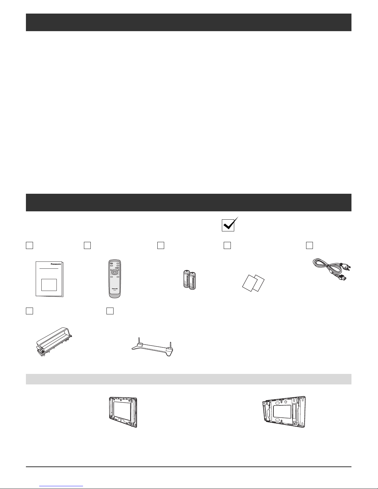
Check that you have the Accessories and items shown
Operating
Instructions
Cable clamper
× 2
Remote control
EUR646539
INPUTPOWER
MUTERECALL
VOL
MENU
RETURN
OK
ASPECT SLEEP
Pedestal
TY-ST42PX5W (TH-42PM50U)
TY-ST50PX5W (TH-50PM50U)
Batteries for the
remote control
(AA Battery × 2)
Optional Accessories
• Wall-hanging bracket
(vertical)
TY-WK42PV3U
• Wall-hanging bracket
(Angled)
TY-WK42PR2U
Product Registration Card
(for U.S.A.)
Customer Care Plan Card
(for U.S.A.)
AC cord
Installation
Location
This unit is intended to be used with the stand or bracket. Consult your dealer for available options. Position for
comfortable viewing. Avoid placing where sunlight or other bright light (including refl ections) will fall on the screen.
Use of some types of fl uorescent lighting can reduce remote control transmitter range.
Adequate ventilation is essential to prevent internal component failure. Keep away from areas of excessive heat or
moisture.
Optional External Equipment
Cables that are not included in the package will need to be obtained separately.
The Video/Audio connection between components can be made with shielded video and audio cables. For best
performance, video cables should utilize 75 ohm coaxial shielded wire. Cables are available from your dealer or
electronic supply store.
Before you purchase any cables, be sure you know what type of output and input connectors your various components
require. Also determine the length of cable you will need.
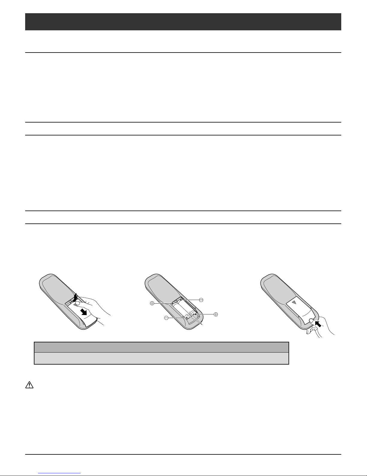
Remote Control Battery Installation
Requires two AA batteries.
1.Turn the transmitter face down.
Press and slide off the battery
cover.
Helpful Hints:
For frequent remote control users, replace old batteries with Alkaline batteries for longer life.
Precaution on battery use
Incorrect installation can cause battery leakage and corrosion that will damage the remote control transmitter.
Disposal of batteries should be in an environment-friendly manner.
Observe the following precautions:
1. Batteries should always be replaced as a pair. Always use new batteries when replacing the old set.
2. Do not combine a used battery with a new one.
3. Do not mix battery types (example: “Zinc Carbon” with “Alkaline”).
4. Do not attempt to charge, short-circuit, disassemble, heat or burn used batteries.
5. Battery replacement is necessary when the remote control acts sporadically or stops operating the Plasma Display.
2.Install the batteries as shown in
the battery compartment.
(Polarity + or – must match the
markings in the compartment.)
Two AA size
3.Replace the cover and slide in
reverse until the lock snaps.
7
2
1
AV
IN
A
U
DI
O I
N
R
L
IN
Y
P
B
P
R
P
B
P
R
COMPONENT VIDEO
INPUT
INPUT 1
INPUT 2
T
O
A
U
D
IO
AM
P
S
VIDE
O
S V
ID
EO
1
2
L
R
VID
E
O
A
UD
IO IN
A
V IN
IN
Y
P
B
P
R
P
B
P
R
C
O
MP
O
N
EN
T
VI
D
E
O
I
NPU
T
I
N
P
U
T
1
I
NPU
T
2
O
UT
PU
T
S
VIDEO
1
2
L
R
V
I
D
E
O
A
U
D
I
O
I
N
R
L
A
U
D
I
O
I
N
P
R
O
G
O
U
T
Y
P
B
PR
Y
P
B
PR
COMPONENT VIDEO
INPUT
INPUT 1 INPUT 2
PROG OUT
S VIDEO
VIDEO
12
L
R
VIDEO
AUDIO IN
AV IN
R L
AUDIO IN
AV IN
R L
AUDIO IN
S VIDEO
VIDEO
L
L
R
R
Y
VIDEO
AUDIO
PB
PR
PB
PR
Y
Y
PROG OUT
TO AUDIO AMP
COMPONENT VIDEO
INPUT
12
INPUT 2 INPUT 1
TO AUDIO AMP
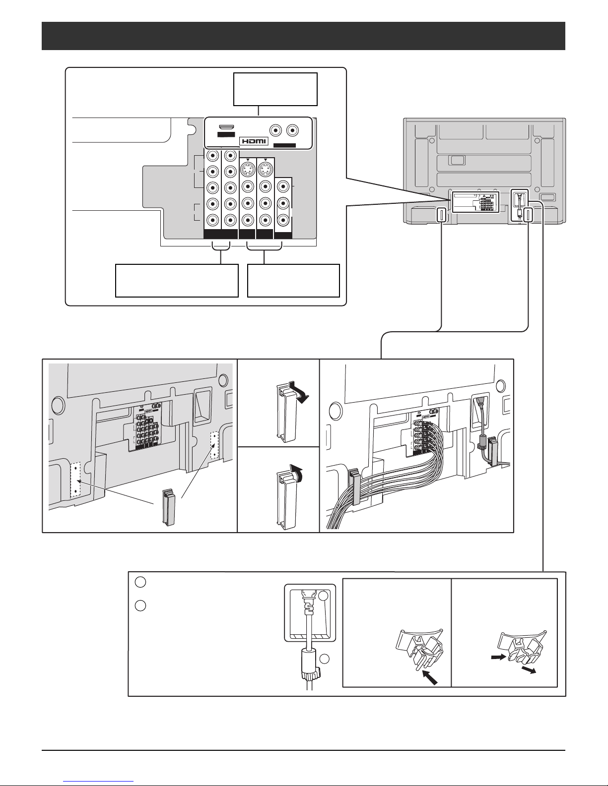
Cable Connection
HDMI terminal
(see page 9)
Clamper
COMPONENT Input
terminals (see page 10)
AC cord fi xing
AV terminals
(see pages 10, 11)
Removal
Fitting
1 Connect power plug to the
socket of the main body.
2 Fix the AC cord clamper.
8
How to fi x:
Fix by pushing in until
a clicking sound is
How to release:
Pull up while drawing
in the knob.
heard.
LR
Y
P
B
PR
Y
P
B
PR
COMPONENT VIDEO
INPUT
INPUT 1 INPUT 2
PROG OUT
TO AUDIO AMP
S VIDEO
12
L
R
VIDEO
AUDIO IN
AV IN
R L
AUDIO IN
HDMI
OUT
AUDIO
OUT
AV IN
R L
AUDIO IN
S VIDEO
VIDEO
L
L
R
R
Y
VIDEO
AUDIO
PB
PR
PB
PR
Y
PROG OUT
TO AUDIO AMP
COMPONENT VIDEO
INPUT
12
INPUT 2 INPUT 1
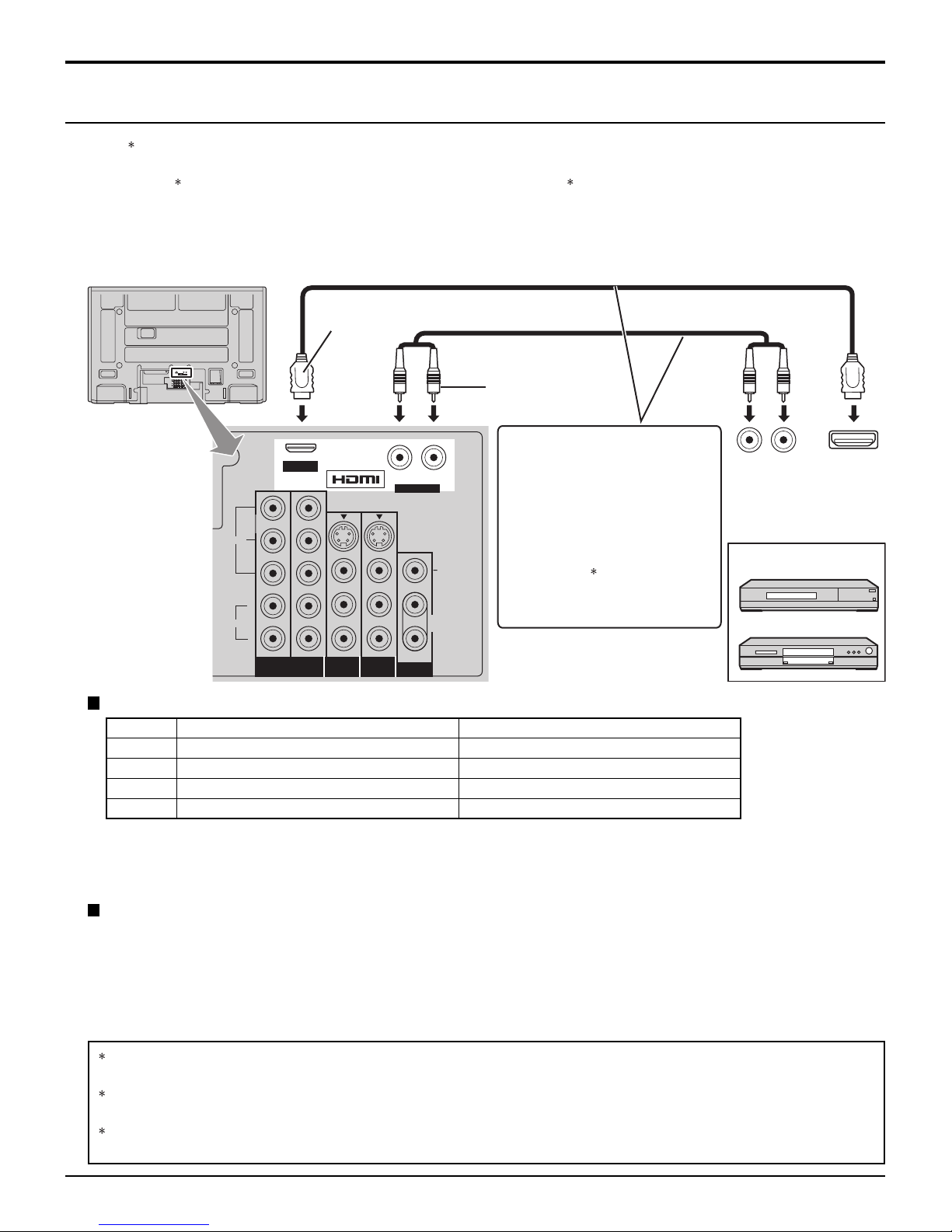
Cable Connection
HDMI Connection
HDMI1 (High Defi nition Multi media Interface) is the fi rst all digital consumer electronics A/V interface that supports
uncompressed standard. The HDMI terminal supports both video and audio information.
To the HDMI
as a Set-Top Box or DVD player with HDMI or DVI output terminal.
Input a High-bandwidth Digital Content Protection (HDCP) high-defi nition picture source to this HDMI terminal, so you
can display high-defi nition pictures on this Display in digital form.
1
input terminal, you can connect an EIA/CEA-861/861B2 compliant consumer electronic device, such
HDMI cable
Audio cable
• If connecting with an HDMI
cable, it is not necessary to
connect an audio cable.
•
If connecting to equipment that
has only a DVI output terminal,
HDMI-DVI conversion cable
and an audio cable are
necessary.
3
HDMI signal out
Set Top Box
• Select the audio setting in
HDMI In (see page 19).
DVD player
Compatible VIDEO Signal
No. of dots (H × V) Vertical scanning frequency (Hz)
1080i 1,920 × 1,080i 59.94/60
720p 1,280 × 720p 59.94/60
480p 720 × 480p, 640 × 480p 59.94/60, 59.94/60
480i 720(1,440) × 480i 59.94/60
Notes:
• This input terminal is not intended for use with computers.
• 1080i and 720p signals will be re-formatted for viewing on your plasma display.
Compatible sampling frequency of AUDIO signal through HDMI (L.PCM) : 48 kHz / 44.1 kHz / 32 kHz
Notes:
• This HDMI connector is Type A.
• If you connect equipment without a digital output terminal, connect to the COMPONENT VIDEO, S VIDEO or VIDEO
input terminal on the Display so you can enjoy an analog signal.
• If you cannot display the picture because your Digital Set-Top Box does not have a DIGITAL OUT terminal Output
setting, use the component Video Input (or the S Video Input or Video Input).
1.HDMI, the HDMI logo and High-Defi nition Multimedia Interface are trademarks or registered trademarks of HDMI
Licensing LLC.
2.EIA/CEA-861/861B profi les compliance covers profi les for transmission of uncompressed digital video including
high bandwidth digital content protection.
3.HDMI-DVI conversion cable (TY-SCH03DH): available from Panasonic Website. Consult your consumer
electronics dealer for availability.
9
10
Cable Connection
Digital TV Set-Top Box (DTV-STB) or DVD Connection
This Display is capable of displaying 1080i, 720p, 480p and 480i DTV signals when connected to a DTV Tuner Set-Top
Box (STB). This Display also utilizes a progressive scan doubler , which de-interlaces the NTSC signal and progressively
scans the image.
• T o view DTV programs, connect the STB to the component video input terminals (Y, P
color inputs provide luminance and separate color signal.
• Set the output of the STB to either 1080i, 720p, 480p or 480i.
• A DTV signal must be available in your area.
• Use a Panasonic DTV-STB (Digital TV Set-Top Box) or DVD Player.
, PR) of the Display . Component
B
COMPONENT
VIDEO OUT
Set Top Box
DVD player
Y
PB
PR
AUDIO OUTPUT
L
R
Audio cable
Note:
All signals will be re-formatted for viewing on your plasma display.
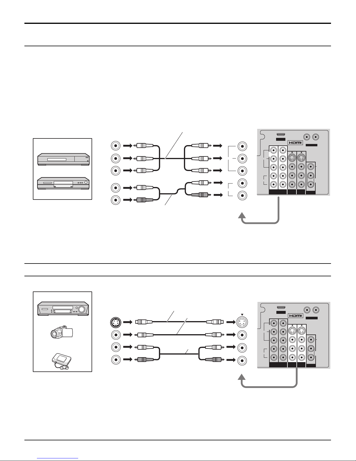
Video Input Connection
Component Video cable
Y
VIDEO
AUDIO
COMPONENT VIDEO
PB
PR
L
R
INPUT 1/2
Back of the Display
AV IN
Y
Y
Y
PR
12
COMPONENT VIDEO
INPUT
PBPRPB
VIDEO
AUDIO
L
R
R L
AUDIO IN
S VIDEO
VIDEO
L
R
TO AUDIO AMP
PROG OUT
INPUT 2 INPUT 1
VCR
CAMCORDER
VIDEO GAME
CONSOLE
S-VIDEO
OUT
VIDEO
OUT
AUDIO
OUT
L
R
Note:
The S Video input will override the composite video signal when S Video cable is connected.
Connect either S Video cable or Video cable.
S-Video cable
or Video cable
Audio cable
INPUT 1 / 2
Back of the Display
AV IN
Y
Y
Y
PR
12
COMPONENT VIDEO
INPUT
PBPRPB
INPUT 2 INPUT 1
VIDEO
AUDIO
L
R
R L
AUDIO IN
S VIDEO
L
R
TO AUDIO AMP
PROG OUT
VIDEO
S VIDEO
VIDEO
L
R
Y
VIDEO
AUDIO
PBPRPB
PR
Y
Y
PROG OUTCOMPONENT VIDEO
INPUT
12
INPUT 2 INPUT 1
TO AUDIO AMP
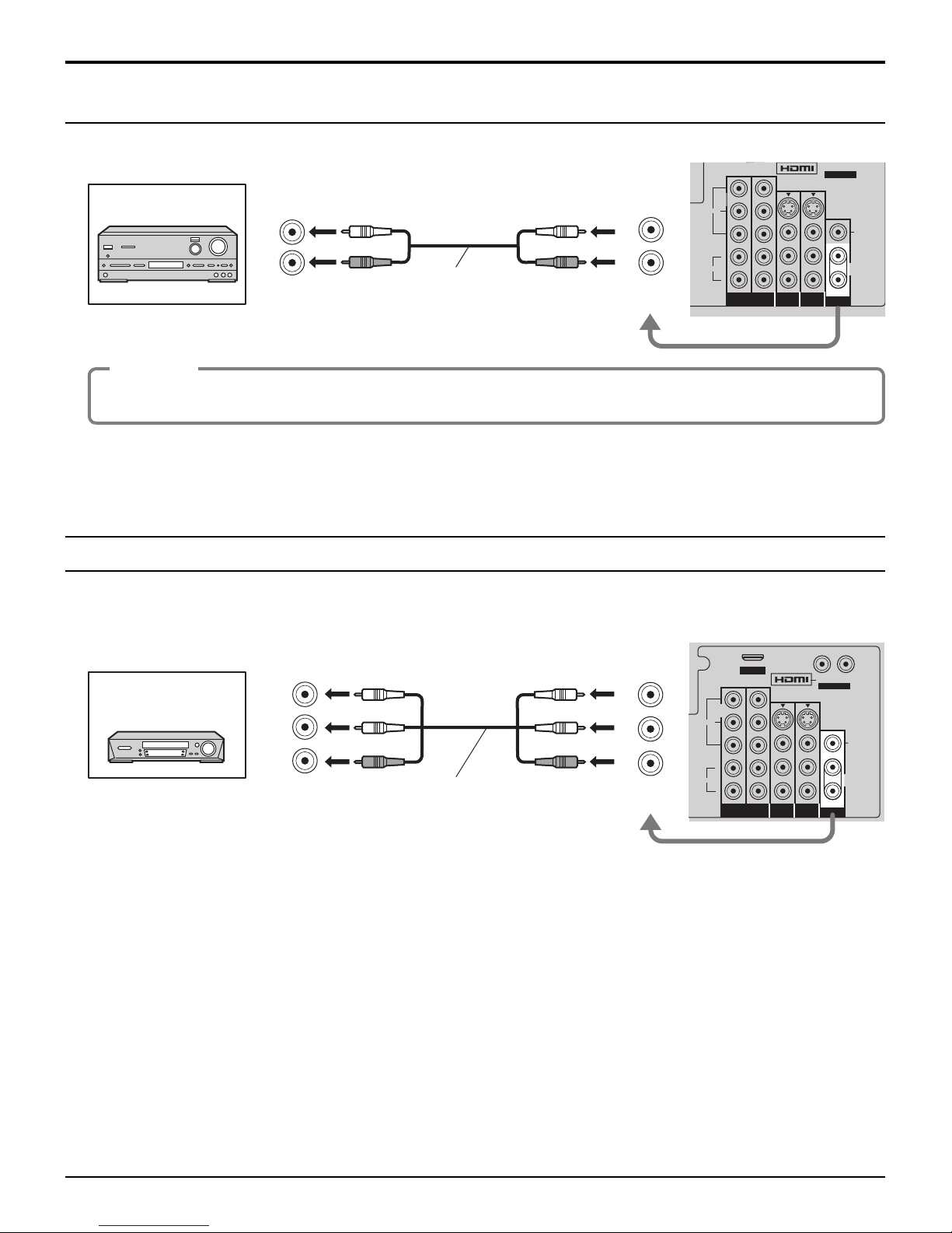
Amplifi er Connection
Cable Connection
Amplifi er
AUDIO INPUT
L
R
Audio cable
L
R
OUTPUT
AUDIO OUT
Procedure
1. Select Speakers “Off” in Audio menu (see page 19).
2. Adjust the amplifi er volume to the desired level.
Note:
External speakers cannot be connected directly to OUTPUT terminals.
Program Out Connection (PROG OUT)
See optional equipment manual for further instructions for recording and monitoring.
Back of the Display
R L
AUDIO IN
L
R
Back of the Display
VCR
DVD recorder
VIDEO
INPUT
AUDIO
INPUT
AV IN
Y
Y
Y
PR
12
COMPONENT VIDEO
INPUT
PBPRPB
L
R
AV cable
OUTPUT
VIDEO
AUDIO
L
R
R L
AUDIO IN
S VIDEO
VIDEO
L
R
TO AUDIO AMP
PROG OUT
INPUT 2 INPUT 1
Note:
When a device (STB, DVD, etc.) is connected to the HDMI or COMPONENT terminals (see pages 9, 10), only audio
signals will be output. No video signals will be output.
11
12
INPUTPOWER
MUTERECALL
VOL
MENU
SLEEP
RETURN
OK
ASPECT
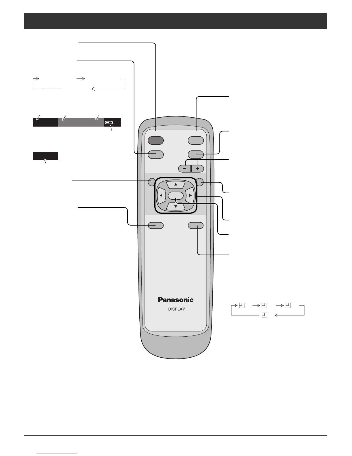
Basic Controls
POWER button
Turn the Display ON or OFF.
RECALL button
Press to switch the banner display.
Large banner Small banner
No banner
Large banner
Video
Video 1 Standard JUST 90
Picture mode
setting
Small banner
Comp. 1
Video
Video
MENU button
Press to switch the main menu
display.
ASPECT button
Press to adjust the aspect.
(see page 16)
Aspect
Time remaining in
Sleep Timer
INPUT button
Press to select Component 1,
Component 2, HDMI, Video 1 and
Video 2 sequentially. (See page 14)
MUTE button
Mute the sound. Press again to cancel
the mute.
V olume Adjustment
Press the Volume Up “+” or Down “-”
button to increase or decrease the
sound volume level.
RETURN button
Press the RETURN button to return to
previous menu screen.
Position buttons
OK button
Press to make selections.
SLEEP button
The Plasma Display can be preset
to switch to Power-OFF after a fi xed
period. The setting changes to 30
minutes, 60 minutes, 90 minutes and
0 minutes (sleep timer cancelled) each
time the button is pressed.
30 60
90
0
Remaining time fl ashes from 3 minutes
before the time is reached.
Pressing the SLEEP button when the
timer is set causes the remaining time
to be displayed. Press the SLEEP
button again while the remaining time
is displayed to change the sleep timer
setting.
INPUTPOWER
MUTERECALL
VOL
MENU RETURN
OK
POWER
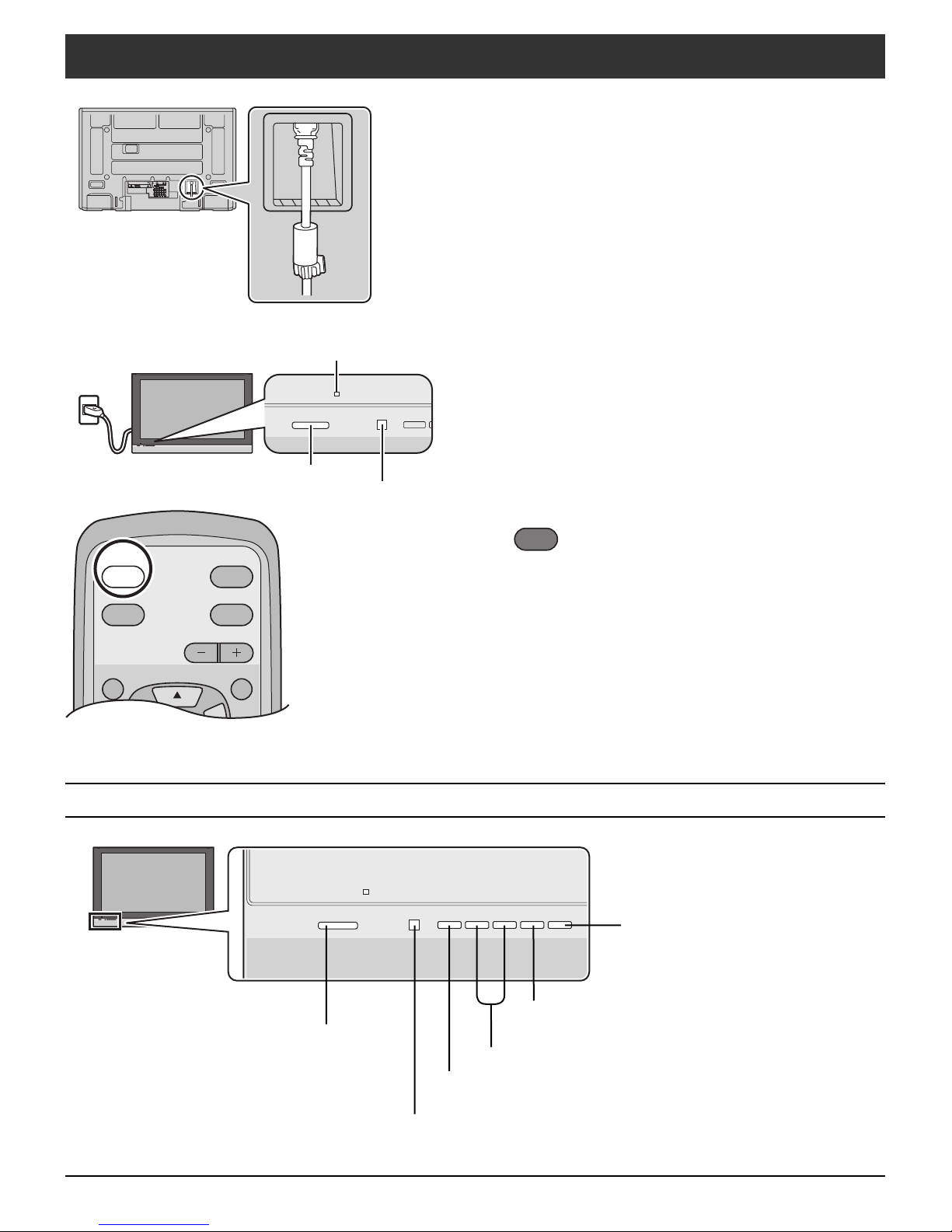
Power ON / OFF
AV IN
R L
AUDIO IN
SERVICE ONLY
Y
Y
ANT
DIGITAL
AUDIO OUT
SERVICE ONLY
B
B
P
P
S VIDEO
VIDEO
PR
PR
L
AUDIO IN
R
12
COMPONENT VIDEO
INPUT 1 INPUT 2 OUTPUT
INPUT
Power indicator Power on : Red
Power off : No Light
POWER
INPUT
Connect the AC cord plug to the Plasma Display.
1
• Fix the power cord plug securely with the clamper
(see page 8).
Connect the plug to the wall outlet.
2
Press POWER button on front of this unit.
3
The Main Unit
POWER button
Remote control sensor
POWER INPUT
or
POWER
Press to turn the Display on or off.
Note:
The Display will still consume some power as long as the
power cord is inserted into the wall outlet.
-
VOL +
ASPECT SLEEP
SLEEP button
Set the sleep timer. (see page 12)
POWER button
Press to turn the Display’s
main power on/off.
ASPECT button
Change the screen aspect. (see page 16)
V olume Adjustment
INPUT button
Change the input mode. (see page 14)
Remote control sensor
Within about 23 feet (7 meters) in front of the Display set.
13
INPUTPOWER
MUTERECALL
VOL
MENU
ASPECT SLEEP
RETURN
OK
MENU RETURN
OK
Setup
Language
English
Setup
Language
English
Initial Selections
INPUTPOWER
MUTERECALL
VOL
MENU
ASPECT SLEEP
RETURN
OK
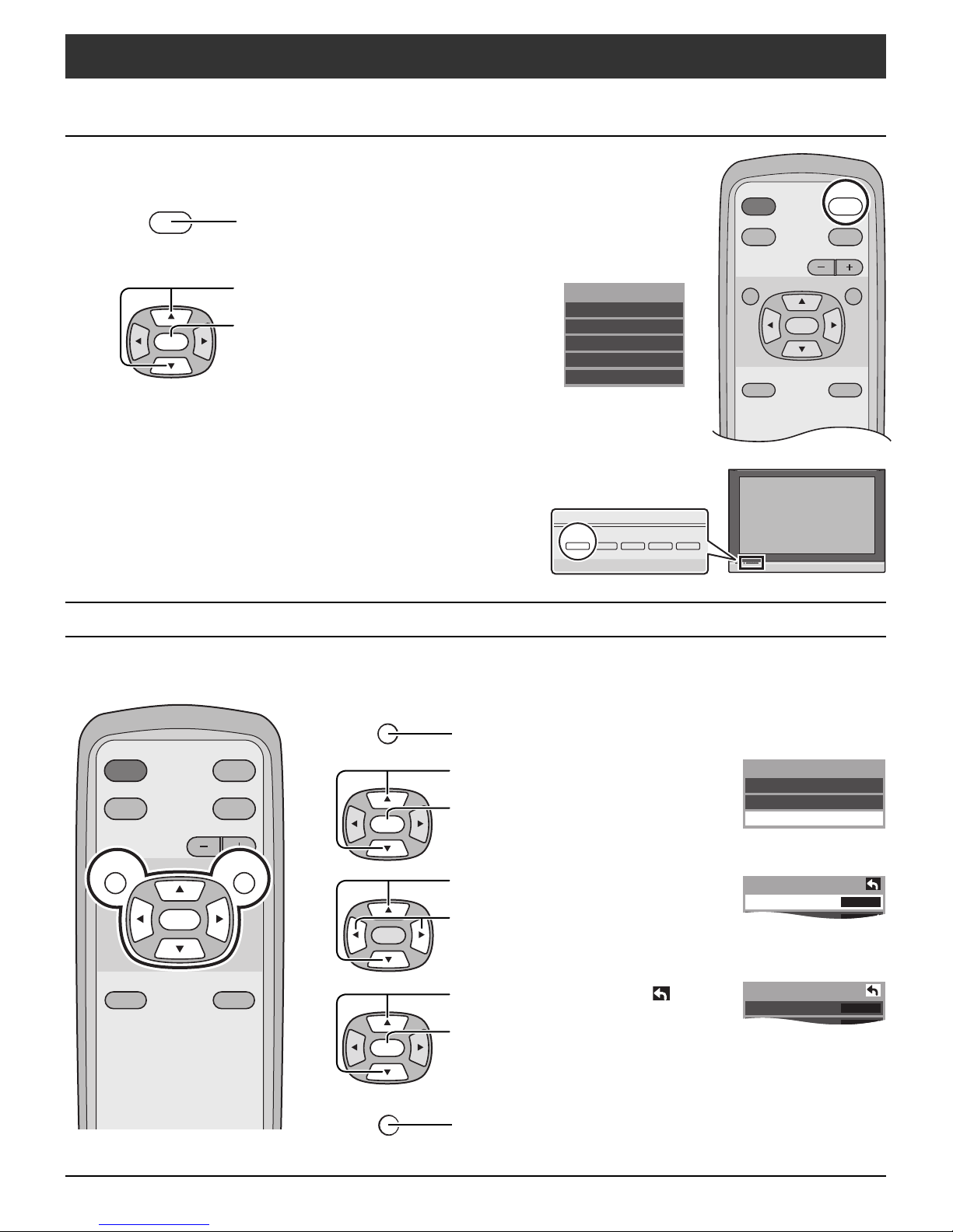
INPUT
Selecting the input signal
Change the input signal.
INPUT
Press to display the input selection menu.
Press to select the input signal.
OK
Press to confi rm.
Alternately, not pressing any button for fi ve
seconds causes the selection to switch to the
highlighted input signal automatically.
[from the unit]
The input signal changes each time the INPUT
button is pressed.
Selecting the Language
Allows you to select the language used for On Screen Displays.
MENU
Press to display the MENU screen.
Input select
Component 1
Component 2
HDMI
Video 1
Video 2
-
VOL +
INPUT
ASPECT SLEEP
14
OK
OK
OK
RETURN
Press to select “Setup”.
Press to display “Setup”
screen.
Press to select “Language”.
Press to select “English”,
“Español” or “Français”.
Press to move the cursor to .
Press to go to previous
screen.
or
Press to return to previous screen.
Menu
Picture
Audio
Setup
INPUTPOWER
MUTERECALL
VOL
MENU
ASPECT SLEEP
OK
MENU RETURN
OK
OK
On
Off
On
Auto
0
Other Adjust
AI Sound
Surround
Speakers
HDMI In
Audio Leveler
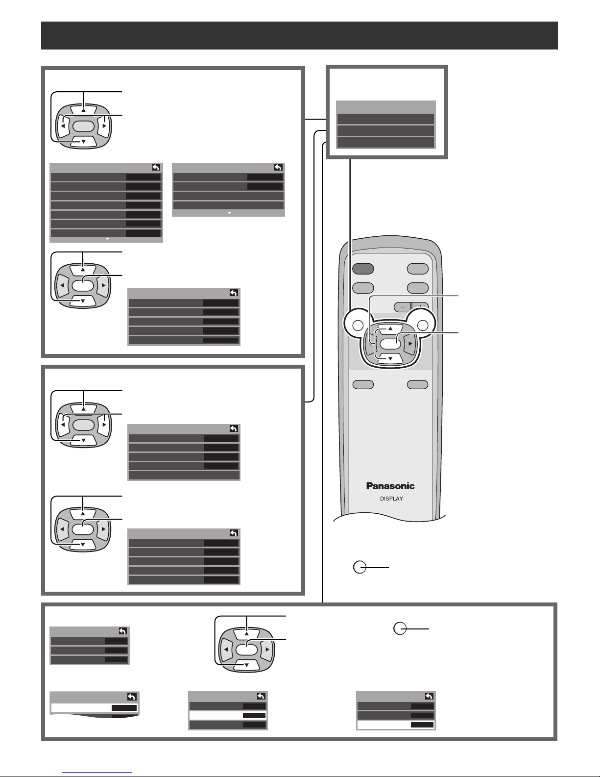
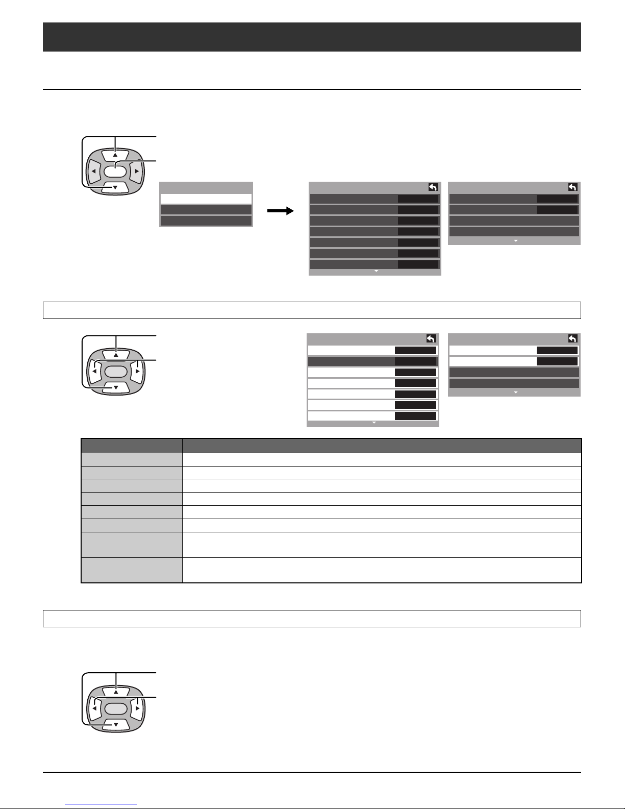
On-Screen Menu Displays for Navigation
Setup
Language
English
Picture adjust (See page 17)
Press to select picture menu.
Press to select or adjust
OK
Picture 1/2
Normal
Pic. mode
Picture
Brightness
Color
Tint
Sharpness
picture items.
No
Standard
+30
0
0
0
+10
Press to select “Other Adjust”.
Press to display “Other Adjust” menu.
OK
Other Adjust
Video NR
3D Y/C Filter
Color Matrix
MPEG NR
Black level
Picture 2/2
Color Temp
Color Mng.
Zoom Adjust
Other Adjust
Off
Off
SD
Off
Dark
Press to display the
Menu screen.
Menu
Picture
Audio
Setup
Cool
Off
Press to select.
Press to enter each
adjust screen.
Audio adjust (See page 19)
OK
Setup (See page 20) Press to select .
Setup
Language
Auto Power On
Side Bar
Press to select Audio menu.
Press to adjust Audio items.
Audio
Normal
Bass
Treble
Balance
Other Adjust
Set
+ 7
+ 7
0
Press to select “Other Adjust”.
Press to display “Other Adjust” menu.
English
Off
Bright
OK
RETURN
Press to go to each
adjust screen.
Press to return to previous menu.
RETURN
Press to return to
previous screen.
Language (See page 20) Side Bar (See page 20)
Auto Power On (See page 20)
Setup
Language
Auto Power On
Side Bar
English
Bright
Setup
Off
Language
Auto Power On
Side Bar
English
Off
Bright
15
16
INPUTPOWER
MUTERECALL
VOL
MENU
ASPECT SLEEP
RETURN
OK
ASPECT
Aspect Controls
ZOOM
4
3
16
9
FULL
4
3
16
9
JUST
4
3 9
16
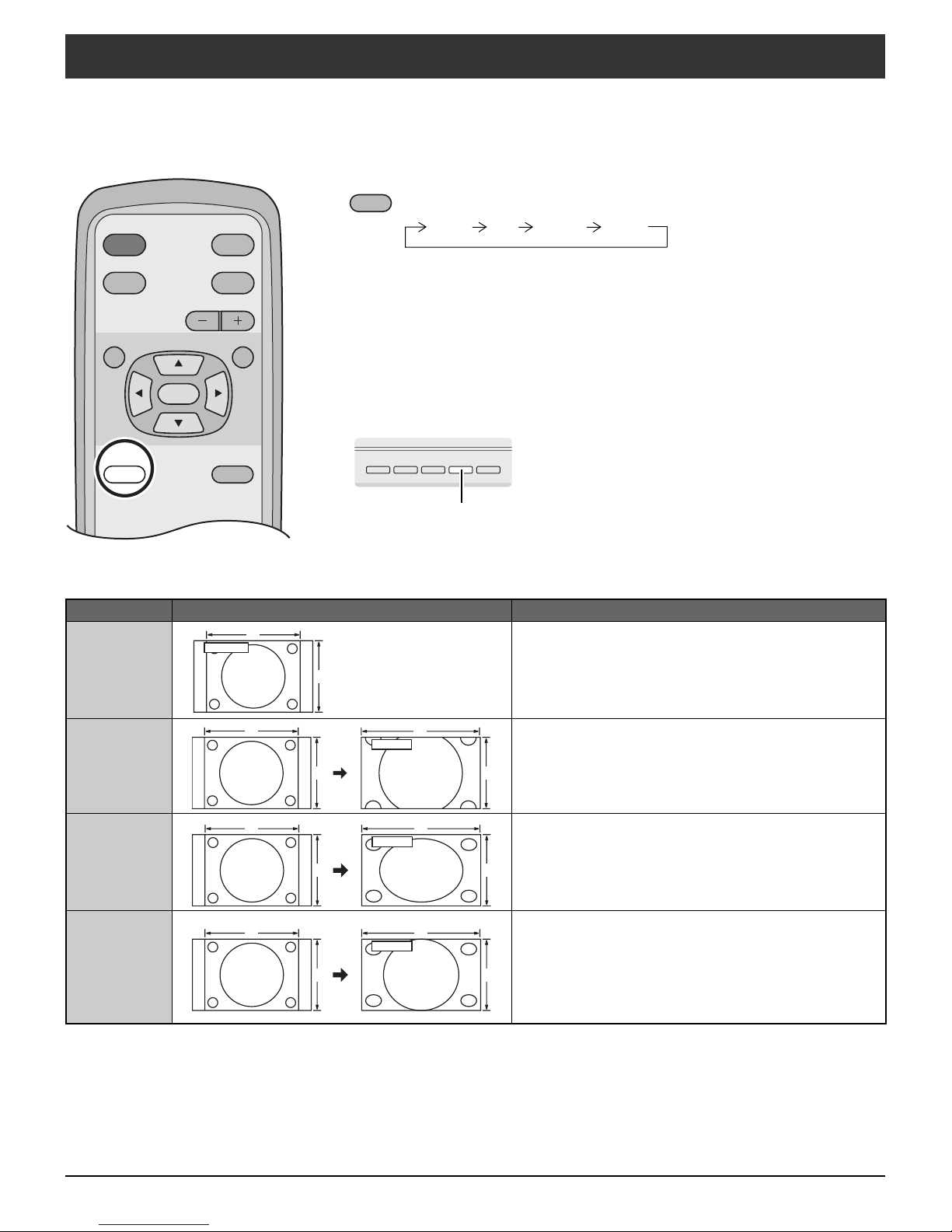
Let you choose the aspect depending on the format of the received signal and your preference.
ASPECT
Press to change the aspect mode.
JUST 4:3 ZOOM FULL
Note:
The available aspect modes depend on the receiving signal.
• 480i, 480p (4:3), 480p (16:9) : 4:3, FULL, JUST or ZOOM
• 1080i/720p : 16:9 only
[from the unit]
INPUT- VOL +
ASPECT
SLEEP
The aspect mode changes each time the ASPECT button is pressed.
Mode Picture Explanation
4
4 : 3
4 : 3
3
Displays a 4:3 picture at its standard 4:3 size with gray
side bars. (It may create an after-image on screen if
displayed for a prolonged period of time.)
ZOOM
FULL
JUST
Expands a 4:3 picture uniformly (width and height)
to full screen width and then repositions the picture
vertically . (Recommended for letterbox. This will show
picture at full screen size.)
Displays a picture at full screen size. (Recommended
for anamorphic pictures.)
Stretches the right and left edges of a 4:3 picture to fi ll
the screen, and the center of the screen has aspect
correction applied. The size of the picture depends on
the original signal.
(Recommended for regular TV viewing.)
Menu Navigation
No
Standard
+30
0
0
0
+10
Picture 1/2
Normal
Pic. mode
Picture
Brightness
Color
Tint
Sharpness
Picture
Press the MENU button to display the Main menu.
Press to select “Picture”.
OK
Menu
Picture
Audio
Setup
Picture 1/2
Normal
Pic. mode
Picture
Brightness
Color
Tint
Sharpness
No
Standard
+30
+10
0
0
0
Picture 2/2
Color Temp
Color Mng.
Zoom Adjust
Other Adjust
Normal / Picture / Brightness / Color / Tint / Sharpness / Color Temp / Color Mng.
Press to enter sub-menu.
Press to select the sub-menu.
Press to adjust the sub-menu.
OK
Item Explanations
Normal Resets all picture adjustments to factory default settings.
Picture Adjusts white areas of picture.
Brightness Adjusts dark areas of picture.
Color Adjusts desired color intensity.
Tint Adjusts natural fresh tones.
Sharpness Adjusts clarity of outline detail.
Color Temp
(Temperature)
Color Mng.
(Color Management)
To increase or decrease Warm (red) and Cool (blue) colors to suit personal
preferences.
Color Mng. On enhances green and blue color reproduction, especially outdoor
scenes.
Picture 2/2
Color Temp
Color Mng.
Zoom Adjust
Other Adjust
Cool
Off
Cool
Off
Pic. mode
Choose the pre-set picture mode that best suits the program you are viewing. This feature also affects Color Temp
setting.
Press to select “Pic. mode”.
Press to select the picture mode.
Note:Each mode has its own picture settings (Picture, Brightness, Color, Tint, Sharpness, Color Temp and Color Mng.).
OK
• Vivid (default) :
• Standard :
• Cinema :
Provides enhanced picture contrast and sharpness for viewing in a well-lit room.
Recommended for normal viewing conditions with subdued room lighting.
For watching movies in a darkened room. It provides a soft, fi lm-like picture.
17
 Loading...