

Panasonic vbhnxxxas06_120725-1 installation
General Installation Manual
HIT Photovoltaic Module
HIT Power 240S series
HIT Power 235S series
HIT Power 230S series
Thank you for choosing Panasonic HIT
photovoltaic (PV) modules. Please read
this manual completely before
installation or use of Panasonic HIT PV
modules. With proper operation and
maintenance, Panasonic HIT PV
modules will provide you with clean,
renewable solar electricity for many
years. This manual contains important
installation, maintenance and safety
information. The word “module” as
used in this manual refers to one or
more PV modules. Retain this manual
for future reference.
SANYO is part of the Panasonic Group
and is in charge of the manufacturing
process for Panasonic HIT PV modules.
Model No.
HIT Power 240S
z VBHN240SA06 and 06B
HIT Power 235S
z VBHN235SA06 and 06B
HIT Power 230S
z VBHN230SA06 and 06B
Contents
Please read before installation
Safety Precautions
z General Information :2
z Warning :2
z Cautions :2
z General Safety :2
z UL Listing Information :2
Installation
z General :2
z Notes on Installation :3
z Operating Conditions :4
Specifications
z Note on Specifications :4
z Mechanical Loading :4
Wiring
z General :4
z Module Wiring :4
z Array Wiring :4
z Earth Ground Wiring :4
z Grounding Locations :5
z Grounding Methods :6
z Module Terminations :6
z Junction Box and Terminals :6
z Conduit :6
Bypass Diodes :7
Maintenance :7
Disclaimer of Liability :7
Customer Services :7
VBHNxxxSA series
1
Safety Precautions
General Information
The installation of solar modules
requires a great degree of skill and
should only be performed by qualified
licensed professionals, including,
without limitation, licensed contractors
and electricians.
WARNING
• All instructions should be read and
understood before attempting to
install, wire, operate, and maintain a
photovoltaic module.
• Contact with electrically active parts
of the module such as terminals can
result in burns, sparks, and lethal
shock whether the module is
connected or disconnected.
• The installer assumes the risk of all
injury that might occur during
installation, including, without
limitation, the risk of electric shock.
• The modules generate DC (direct
current) electrical energy when
exposed to sunlight or other light
sources. Even a single module
produces enough voltage and
current, to cause shocks and burns if
safety precautions are not followed.
• The shock hazard increases as
modules are connected in parallel,
producing higher current, and as
modules are connected in series,
producing higher voltages.
• To avoid the hazard of electric
sparks, shock, fire, burns, damage
and injury:
• Work only in dry conditions, with dry
modules and dry tools.
• Do not stand or step on modules. Do
not puncture, cut, scratch or
damage the backsheet of a module.
Backsheet damage will void a
module’s Limited Warranty and may
cause fire.
damaged back sheet.
• Do not allow children and
unauthorized persons near the
installation or storage site of
modules.
• Completely ground all modules.
• Do not disassemble a module,
attempt any repair, open the
junction box cover, nor remove any
parts installed by Sanyo. There are
no user serviceable parts within the
module or junction box.
Never use modules with a
• Unauthorized persons - except the
qualified licensed professional should not perform any electrical
work, including wiring,
• Wear suitable clothing, guards, eye
protection and gloves to prevent
you from direct contact with 30 VDC
or greater.
• Wear non-slip gloves and carry
modules by the frame using both
hands. Do not attempt to carry a
module by yourself.
• Do not carry a module by its wires or
junction box.
• Do not drop anything on the surface
of a module.
• Ensure all system components are
compatible, and they do not subject
the module to mechanical or
electrical hazards.
• Sparks may occur; do not install
modules where flammable gases or
vapors are present.
• Never rest or leave a module
unsupported or unsecured.
• Do not drop modules.
• Do not use or install broken modules.
• Do not artificially concentrate
sunlight on a module.
• Do not touch the junction box
terminals.
• Do not change the wiring of bypass
diodes.
• Do not touch a module unnecessarily.
The glass surface and frames get hot.
There is a risk of burn.
CAUTIONS
• Use a module for its intended
purpose only.
• Do not treat the back sheet, frame,
or front surface with paint or
adhesives, to avoid reducing its’
functionality, damage, and causing
inoperable conditions, and other
unknown troubles.
• Do not insert PV cable between back
side and mounting structure rail.
GENERAL SAFETY
• Follow all permissions, installation
and inspection requirements.
• Before installing modules, contact
the appropriate authorities having
jurisdiction to determine permissions,
installation and inspection
requirements, which should be
followed.
2
• Electrically ground modules for all
systems of any voltage. If not
otherwise specified, it is
recommended that requirements of
the latest National Electrical Code
(USA) or Canadian Electric Code
(Canada) or other national or
international electrical standards be
followed. Refer to “Earth Ground
Wiring” section for more
information.
• Be sure that the building or structure
(roof, façade, etc.) where the
modules are being installed has
enough strength to support the load
of the modules.
• For modules mounted on roofs,
special structures may be required to
help provide proper installation
support.
• Both, roof construction and module
installation design have an effect on
the fire resistance of a building.
Improper installation may contribute
to fire hazards. Additional devices
such as ground fault, fuses, and
disconnects may be required.
• Do not use modules of different
specifications in the same system.
• Follow all safety precautions of
other system components which are
used.
UL Listing Information
To satisfy UL requirements, when
installing the modules, be sure to:
1) Use only stranded or solid copper
single–conductor sunlight-resistant
cable rated for outdoor use (e.g.
type UF or USE) , for all wiring that is
exposed to weather.
2) Observe the requirements described
in sections labeled INSTALLATION
and SPECIFICATIONS
.
INSTALLATION
General
Please read this guide completely
before installing or using your
Panasonic HIT PV modules. This section
contains important electrical and
mechanical specifications.
• Modules should be firmly fixed in
place in a manner suitable to
withstand all expected loads,
including wind and snow loads.
• Metals used in locations that are
exposed to moisture shall not be
employed alone or in combinations
(
)
(
that could result in deterioration or
corrosion.
• Install modules where they are not
shaded by obstacles like buildings
and trees. Pay special attention to
avoid partially shading the modules
by objects during the daytime.
• If needed, contact an Authorized
Representative with questions
regarding mounting profiles for
Panasonic HIT PV modules.
Notes on Installation
• Clearance between the roof surface
and module frame is required to
allow cooling air to circulate around
the back of the module. This also
allows any condensation or moisture
to dissipate. Install modules with a
minimum of 1 inch clearance
between the roof surface and the
modules so that air can circulate.
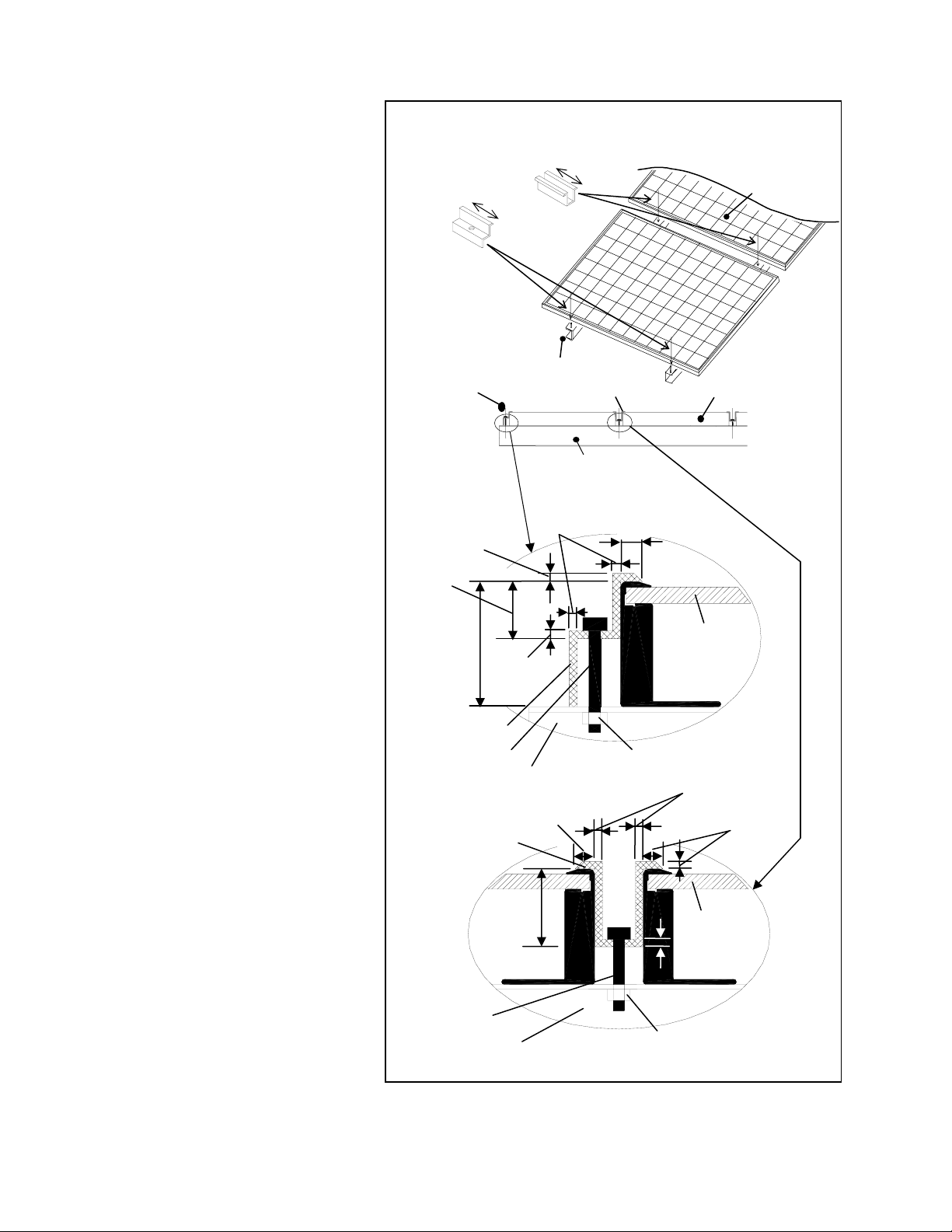
• SANYO recommends the installation
method and mounting profile
shown in Figure 1
• A module should be attached on a
mount or support structure rail by
corrosive-resistant metal clamps.
• The clamps should be made of
aluminum alloy or other material
that will reasonably protect against
a risk of electrolytic corrosion.
• Recommendation of bolt torque
range: 16N.m to 20N.m
• The module was tested using Unirac
clamps with the specifications see
figure 1 and below;
¾ Provider: UniRac, Inc.
¾ Part number: SolarMount®
¾ Clamps type: Top Mounting
Clamps
¾ Clamp size:Mid clamp and End
clamp, C size,
¾ Unirac Part No. 302003, 302101
¾ Width: 1.5”(38 mm)
¾ Thickness : 0.12”(3 mm)
¾ Torque range: 16N.m to 20N.
¾ Material: Aluminum Alloy (6005-
T5, 6105-T5, 6061-T6)
• If another clamp except Unirac is
used it must have material (alloy
designations), physical dimension
and capture area with specifications
as bellow;
¾ Thickness : 0.12”(3 mm) or more
¾ Material: Aluminum Alloy (6005-
T5, 6105-T5, 6061-T6)
• Sanyo does not provide a warranty
for clamps. The module warranty
Sanyo provides shall be voided if
Installation (reference)
1.5”
(38mm)
Metal clamp B
(2 places)
Metal clamp A
(2 places)
Mounting
Structure Rail
Metal clamp A
Mounting Structure
Rail
0.2” (5mm)
0.62”
(16mm)
1.37”
(35mm)
0.18”
(4.6mm)
Metal clamp A
M8 Bolt
Mounting Structure
0.2”
(5mm)
Metal clamp
0.43”
(11mm)
M8 Bolt
Mounting Structure
3
1.5”
(38mm)
Metal clamp B Solar Module
0.12”
3mm
End of Module
Between Modules
Figure 1. Installation
0.2” (5mm)
M8 Nut
0.2”
(5mm)
M8 Nut
Module
0.12”
3mm)
Solar Module
0.2”
(5mm)
Modul

clamps selected by the customer are
of an improper material or size
Operating Conditions
SANYO requires that modules are
operated within the following Operating
Conditions:
1) Terrestrial applications only—no
outer space or Special Conditions
(see below).
2) The ambient temperature must be
within –20°C (-4°F) to 46°C (115°F).
The temperature limits are defined
as the Monthly Average High or Low
of the installation site.
3) The wind pressure load of the
installation site should be less than
2,400N/m
4) Some environmental conditions
could apply. Please refer to Sanyo’s
warranty exclusions.
2
(50PSF)
SPECIFICATIONS
Notes on Specifications
1) Rated electrical characteristics are
within –5% to +10% of the values
measured at Standard Test
Conditions (STC). STC conditions are;
Irradiance of 1000W/m
temperature, and solar spectral
irradiance per IEC 60904-3. Note: At
the time of shipment, Sanyo
guarantees the output level of its
modules to be -0/+10% against
Rated Power in SPECIFICATIONS
based on Sanyo’s factory inspection
at STC conditions.
2) Under real conditions, a photovoltaic
module may experience conditions
that produce more current and/or
voltage than reported at Standard
Test Conditions. Therefore, the Isc
value of modules should be
multiplied by a factor of 1.25 to
determine ampacity. An additional
factor of 1.25 may be required for
sizing conductors, fuses, disconnects,
etc. Please refer to section 690.8 of
the National Electric Code (NEC) for
guidelines. The Voc must be factored
according to the lowest recorded
ambient temperature recorded for
the location where the modules will
be installed. Please refer to section
690.7 of the NEC for more
information regarding voltage
temperature factors.
3) The current output for the modules
shown in the SPECIFICATIONS
section is measured at Standard Test
2
, 25°C cell
Conditions. These conditions may
not be frequently observed in actual
practice.
Mechanical Loading
• The modules should be mounted at
the four (4) quarter points by the
means shown in Figure 2.
• This method offers a maximum load
of 2,400N/m2 (50PSF) in a static
state on the module surface.
• Note: This mechanical loading value
was tested using the mounting
device specified in section “Notes on
Installation”.
WIRING
General
• All wiring should be done in
accordance with applicable electrical
codes.
• Wiring methods should be in
accordance with the NEC in USA or
CEC in Canada.
• A qualified, licensed professional
should do all wiring.
• Wiring should be protected to help
ensure personal safety and to
prevent damage.
• All modules connected in series
should be of the same model
number and/or type.
• Do not connect modules in parallel
without using a connection box that
connects appropriate FUSE for each
series string or each module.
• Do not disconnect terminals while
modules generate electricity and
connect electrical load to avoid the
hazard of electrical shock.
• To avoid the hazard of electric shock
and sparks, please connect each
cable after confirming the polarity of
them is correct.
• Cable conduits should be used in
locations where the wiring is
inaccessible to children or small
animals.
Module Wiring
• The number of modules that can be
wired in series is recommended to be
ten (10) or fewer. If connecting
eleven (11) modules in series, check
local temperature conditions and
follow the National Electric Code
(690.7) to ensure compliance with
maximum voltage limitations.
4
• Modules are not designed for “off-
grid” or battery charging systems,
because of their operating voltage.
Therefore, it is not recommended to
use them for charging batteries.
• These modules contain factory
installed bypass diodes. If these
modules are incorrectly connected to
each other, the bypass diodes, cable,
or junction box may be damaged.
Array Wiring
• The term “array” is used to describe
the assembly of several modules on
a support structure with associated
wiring.
• Use copper wire which insulation is
sunlight resistant and can withstand
the maximum possible system open
circuit voltage.
• Interconnection of modules must be
performed in a professional fashion.
Wires should be secured and only
reasonable slack should be allowed.
• Check local codes for requirements.
Earth Ground Wiring
• All modules should be grounded. All
structures or metallic components in
direct contact with the modules or
electric wires should be properly
grounded too. To avoid the hazards
of electric shock or fire, modules
should be grounded by the frame
only at the locations marked in this
manual (see grounding methods
below).
• The array frame shall be grounded in
accordance with NEC Article 250
(USA) or the CEC in Canada.
• Bonding shall be by a positive means,
such as clamping, riveting, bolted or
screwed connectors, or welding,
soldering or brazing. If the bonding
means depends upon screw threads
two or more screws or two full
threads of a single screw must
engage the metal
• Great care should be exercised to
ensure that corrosion caused by the
grounding means be avoided.
• Corrosion can increase the resistance
of the grounding connection on the
module, or can even cause the
grounding connection to fail entirely.
Corrosion can be caused by the
effects of weather, humidity, dirt
and so on. It can also be caused
when two dissimilar metals are in
contact (galvanic reaction).
 Loading...