

Panasonic Varicam LT User Manual

LT
Operating Guide
Version 1
* The photograph is an example of a system.
W0316HM0 -YI VQT5M58A(E)

f SDXC logo is a trademark of SD-3C, LLC.
f MMC (Multi Media Card) is a registered trademark of Inneon Technologies AG.
f Microsoft
f Screenshots are used according to Microsoft Corporation guidelines.
f Apple, Macintosh, Mac OS, QuickTime, iPad, iPhone, and ProRes are trademarks or registered trademarks of Apple Inc. in the United States and/or
other countries.
f All other names, company names, product names, etc., contained in this document are trademarks or registered trademarks of their respective
owners.
f This product is licensed under the AVC Patent Portfolio License. All other acts are not licensed except private use for personal and non-prot purposes
such as what are described below.
f The Apple ProRes codec module is used under license from Atomos.
f Atomos is a trademark or registered trademark of Atomos Global Pty. Ltd.
®
and Windows® are registered trademarks or trademarks of Microsoft Corporation in the United States and/or other countries.
- To record video in compliance with the AVC standard (AVC Video)
- To play back AVC Video that was recorded by a consumer engaged in a personal and non-commercial activity
- To play back AVC Video that was obtained from a video provider licensed to provide the video
Visit the MPEG LA, LLC website (http://www.mpegla.com/) for details.
How to read this document
r Illustrations
f Illustrations may differ from the actual product.
r Conventions used in this manual
f Words and phrases in [ ] brackets indicate details and content displayed in the viewnder or control panel.
f Words and phrases in < > brackets indicate design text used on this camera, such as button names.
r Reference pages
f Reference pages in this document are indicated by (page 00).
r Terminology
f SD memory card, SDHC memory card, and SDXC memory card are referred to as “SD memory card”.
f A memory card with the “P2” logo such as AJ-P2E060FG memory card (optional) is referred to as a “P2 memory card”.
f A memory card with the “expressP2” logo such as AU-XP0256AG memory card (optional) is referred to as a “expressP2 memory card”.
f P2 memory card and expressP2 memory card are referred to only as “P2 card” unless distinguished otherwise.
f Video that is created during a single recording operation is referred to as a “clip”.
r Combining the products
f This document describes with assumption to use in the following combination of products.
- Camera: AU-V35LT1G
- Electronic HD color view nder: AU-VCVF10G
- Shoulder mount module: AU-VSHL2G
- Grip module: AU-VGRP1G
- PL lens mount module: AU-VMPL1G
– 2 –

Contents
Contents
Chapter 1 Overview 5
Before using the camera 6
Accessories/options 7
Camera 7
Electronic HD color view nder (optional: AU-VCVF10G) 7
Shoulder mount module (optional: AU-VSHL2G) 7
Grip module (optional: AU-VGRP1G) 7
PL lens mount module (optional: AU-VMPL1G) 7
Use of the camera on a system 8
Basic system devices 8
Expansion system devices 8
Accessories 8
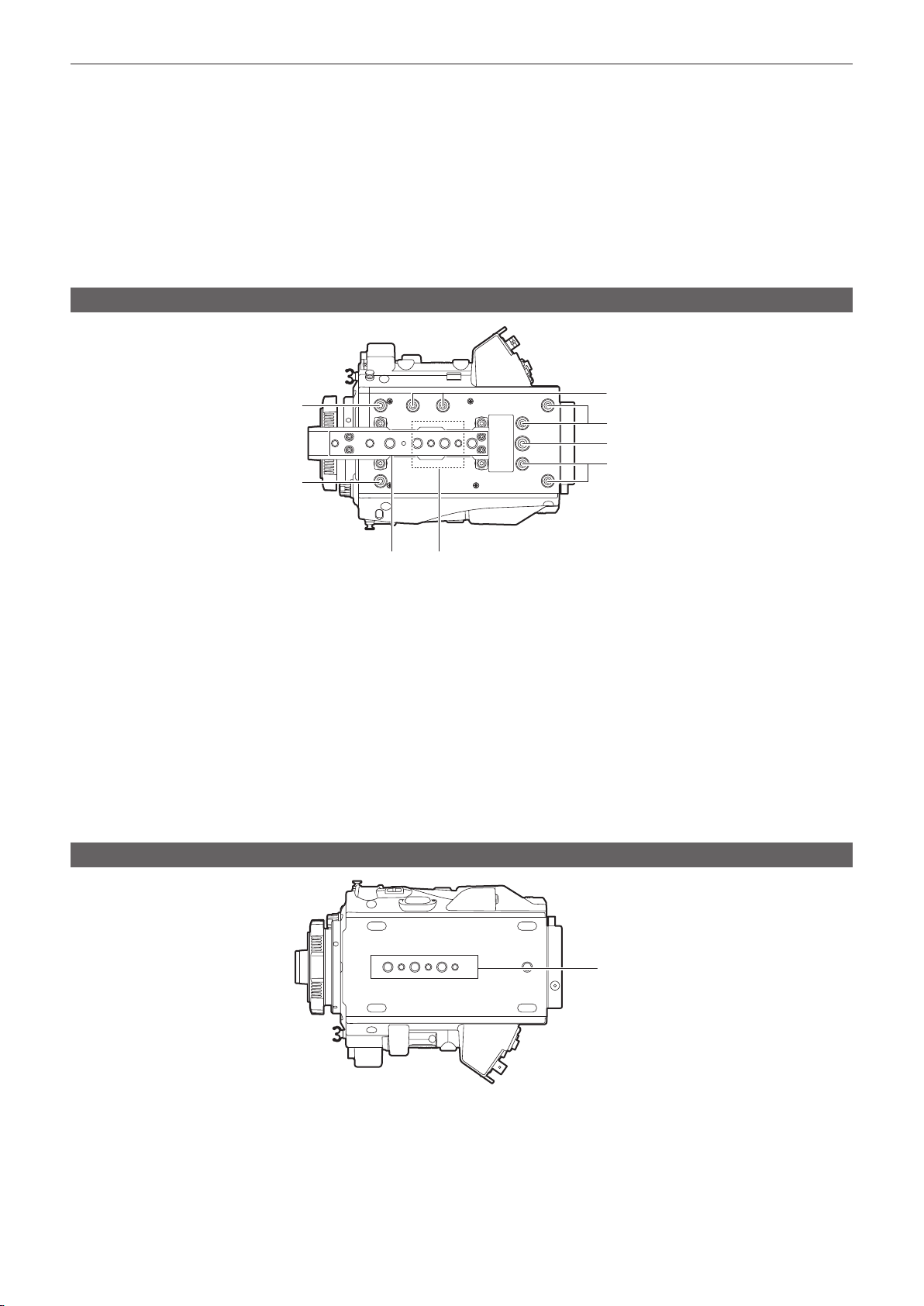
Chapter 2 Description of Parts 9
Camera 10
Left side 1 0
Right side 11
Front 12
Rear 12
Top 1 3
Bottom 1 3
Electronic HD color view nder 14
Left side 1 4
Front 14
Rear 15
Top 1 5
Shoulder mount module 16
Left side 1 6
Right side 16
Front 16
Rear 16
Top 1 6
Grip module 17
Left side 1 7
Top 1 7
Left side (grip arm) 1 7
Right side (grip arm) 17
PL lens mount module 18
Left side 1 8
Right side 18
Front 18
Rear 18
Chapter 3 Preparation 19
Mounting the module 20
Mounting the control panel 2 0
Mounting the electronic HD color view nder 2 1
Mounting the shoulder mount module 22
Mounting the grip module 23
Attaching and removing accessories 24
Eye cup/eye piece lter 2 4
Attaching a tripod 2 4
Rain cover 25
Power supply 26
Using batteries 2 6
Mounting and setting battery 2 6
Using the external DC power supply 27
Switching between external DC power supply and battery
power supply 28
Mounting and adjusting the lens 29
EF lens 29
PL lens 3 0
Flange lens back adjustment 3 1
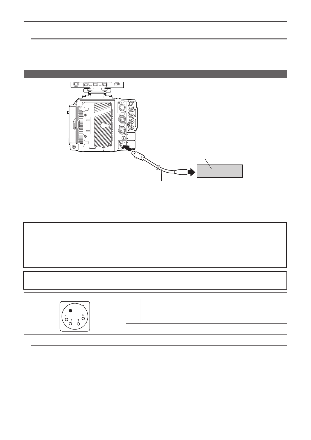
Connecting to the DC output terminal 32
Connecting the <DC OUT/RS> terminal to the external
recording start/stop switch 32
Connecting to the <DC OUT> terminal 32
Charging the built-in battery 33
Setting the date/time of the internal clock 34
Inspections before shooting 35
Chapter 4 Video Recording and Color Grading 36
Dual-recording 37
File name style 38
Selecting the resolution, codec, and video format for
recording 40
Color setting 45
COLOR screen setting 4 5
Control combinations through settings 4 5
[MAIN COLOR] setting 45
[Grading SEL] setting 4 6
[PROXY COLOR] setting 4 6
[3D LUT] setting 4 6
[CDL] setting 4 7
[SDI SET] 49
Image quality adjustment 50
[WHITE] 5 0
[BLACK] 51
[GAMMA] 52
[KNEE] 5 3
[WHITE CLIP] 5 3
[DETAIL] 5 4
[SKIN DETAIL] 5 4
[CHROMA] 5 5
[MATRIX] 5 5
[COLOR CORRECTION] 56
Memory card 57
Insert memory card 5 7
Ejecting the memory card 5 7
To prevent unintentional erasing 5 8
Status of card access LED and P2 card 5 8
Status of card access LED and SD memory card 5 8
Recording time of memory card 5 9
How to handle data recorded on P2 cards 5 9
Formatting a P2 card 6 0
Special recording functions 61
HD cutout high speed recording 61
IR recording 6 1
Shot mark recording function 62
Text memo recording function 6 2
Pre-recording 6 3
Interval recording 63
One-shot recording 63
Chapter 5 Operation 65
Control panel operation 66
Camera status display 6 6
HOME screen 68
PLAY screen 70
TC screen 71
INFO screen 72
VIEW screen 73
MENU screen 74
Operation of the camera buttons 75
Chapter 6 Audio recording 78
Preparing for audio input 79
When using a stereo microphone 79
Using audio devices 80
Selecting audio input and adjusting recording levels 81
Selecting audio input signals 81
Adjusting the recording levels 81
Audio monitor 82
Chapter 7 Viewnder 83
Adjusting and setting the viewnder 84
Adjustment method 8 4
Viewnder status display 85
Lamp display 85
Status display 85
Convenient shooting functions 88
Zebra patterns display 88
Displaying the center marker 88
Displaying the safety zone marker 88
Displaying frame marker 88
Focus assist function 88
False color mode 89
– 3 –

Contents
Chapter 8 Output and Screen Display 91
FTP client function setting 167
Transferring (copying) from the main slot to the FTP server 167
Output 92
Output format list 92
Screen status display 93
Status display (STATUS) 93
Chapter 9 Other Useful Functions 94
Getting position information using the GPS 95
Assigning functions to the USER buttons 96
Selectable functions 96
Handling setting data 98
File structure of the setting data 98
Handling SD memory cards 98
Performing operations on SD memory cards 99
Setting the time data 101
Denition of time data 101
User bits settings 101
How to input user bits 101
Setting the time code 102
Externally locking the time code 102
Supplying the time code externally 104
Chapter 12 Maintenance 169
Warning system 170
Cases indicated by error codes 170
Cases indicated by error messages 170
Updating the camera rmware 173
Updating the rmware 173
Cleaning and storing 174
Cleaning the camera body 174
Cautions when storing the camera recorder 174
Chapter 13 Specication 175
Specications 176
Dimensions 176
Specications 177
Index 180
Connection through the <USB DEVICE> terminal 106
Connecting to a computer in the USB device mode 106
Chapter 10 Menu Operations 107
Setting menu structure 108
Menu conguration 108
Setting menu display 109
Setting menu basic operations 109
Setting menu initialization 109
Menu list 110
[SYSTEM SETTINGS] 11 0
[CAMERA SETTINGS] 11 5
[SCENE FILE SETTINGS] 117
[REC SETTINGS] 122
[AUDIO SETTINGS] 123
[OUTPUT SETTINGS] 125
[FILE] 131
[PERIPHERAL] 131
Initial value of the scene le 134
[CAMERA SETTINGS] 134
[SCENE FILE SETTINGS] 134
Menu operations 137
[SYSTEM SETTINGS] 137
[CAMERA SETTINGS] 138
[SCENE FILE SETTINGS] 139
[REC SETTINGS] 141
[AUDIO SETTINGS] 141
[OUTPUT SETTINGS] 142
[FILE] 144
[PERIPHERAL] 144
Target items for saving and initialization 146
[SYSTEM SETTINGS] 146
[CAMERA SETTINGS]
[SCENE FILE SETTINGS] 148
[REC SETTINGS] 150
[AUDIO SETTINGS] 150
[OUTPUT SETTINGS] 151
[FILE] 153
[PERIPHERAL] 153
147
Chapter 11 Network Connection 155
Network connection 156
Available functions 156
Preparing for connection 157
For wireless module AJ-WM30 157
For wireless module other than AJ-WM30 158
For wired LAN 159
Network settings 160
Wireless LAN settings 160
4G/LTE setting 162
Wired LAN settings 162
Checking network setting 163
Changing network setting 164
Connecting the remote operation panel (AK-HRP200G) 166
Setting for connection with the remote operation panel
(AK-HRP200G) 166
Using the FTP client function 167
– 4 –

Chapter 1 Overview
Before using the camera, read this chapter.

Chapter 1 Overview — Before using the camera
Before using the camera
r Before using the camera, always check if the built-in battery is not consumed, and then set the date/time.
The internal clock of the camera is reset when the built-in battery has been consumed. This may result in the metadata of the clip not recorded correctly,
and it may not display correctly in the thumbnail screen.
Check if the built-in battery is not consumed before using. (page 33)
Also, set the correct date/time. (page 34)
r Cautions when throwing memory cards away or transferring them to others
Formatting memory cards or deleting data using the functions of the camera or a computer will merely change the le management information: it will
not completely erase the data on the cards. When throwing these cards away or transferring them to others, either physically destroy them or use a
data deletion program for computers (commercially available) to completely erase the data. Users are responsible for managing the data stored in their
memory cards.
r Control panel and viewnder
f If the same image or letters are allowed to be displayed on the control panel for a long time, the image may be burned into the screen. It will return to
normal after leaving the camera recorder turned off for several hours.
f Condensation sometimes forms on the LCD of the control panel in locations subject to extreme temperature differences. If this happens, wipe with a
soft, dry cloth.
f If the camera recorder is very cold, the control panel will be slightly darker than normal immediately after the power is turned on. It will return to its
regular brightness when the temperature inside increases.
f Since the viewnder uses organic EL, if the same image or letters are allowed to be displayed for a long time, the image may be burned into the
screen. There is no problem with the recorded images.
Switch the screen by turning off the screen or by using the eye sensor, etc.
f The control panel and viewnder monitor (organic EL) are highly-precisely managed so that at least 99.99% of the dots are effective pixels and 0.01%
or less are invalid pixels and always lit. This is not a malfunction and it has no effect whatsoever on the recorded images.
r Do not point the eye piece of the lens and viewnder at the sun.
Doing so might damage the components inside.
r GPS
GPS (Global Position System) satellite is managed by the United States Department of State and its precision is sometimes intentionally changed.
Position it in a location where there is a good view of the sky and there is no inuence of obstacles such as roofs and trees, etc.
Depending upon the surrounding environment and the time, it may take a long time to position and errors may be larger.
r Caution regarding laser beams
The image sensor may be damaged if the image sensor is exposed to the laser beam.
Take sufcient care to prevent laser beams from striking the lens when shooting in an environment where laser devices are used.
r Note the following points.
f If you prepare to record important images, always shoot some advance test footage to verify that both pictures and sound are being recorded
normally.
f Should video or audio recording fail due to a malfunction of the camera or the P2 cards used, we will not assume liability for such failure.
f Set up or check the calendar and time zone before recording. (page 34) These settings have an effect on the management and playback order of
the recorded contents.
r Software information about this product
1 This product includes software licensed under GNU General Public License (GPL) and GNU Lesser General Public License (LGPL), and
customers are hereby notied that they have rights to obtain, re-engineer, and redistribute the source code of these software.
2 This product includes software licensed under MIT-License.
3 This product includes software developed by the OpenSSL Project for use in the OpenSSL Toolkit (http://www.openssl.org/).
4 This product includes software licensed under OpenBSD License.
5 This product includes PHP, freely available from <http://www.php.net/>.
6 This software is based in part on the work of the Independent JPEG Group.
7 This product includes software licensed under MOZILLA PUBLIC LICENSE.
For details on these descriptions (originally provided in English) and how to obtain the source code, visit the following website.
http://pro-av.panasonic.net/
We do not accept inquiries about the details of the source code obtained by the customer.
r Precautions when installing USB drivers
For the latest information on the driver, visit the following website.
http://pro-av.panasonic.net/
f Install the required driver into your computer from the website.
f For installation procedure of the driver, refer to the installation manual on the website.
– 6 –

Chapter 1 Overview — Accessories/options
Accessories/options
Camera
f Mount cap (already attached to the camera module)
f Control panel
f Control panel mounting part
f Glass for IR recording
f Control panel mounting part clamping screw (4 pcs.)
Electronic HD color view nder (optional: AU-VCVF10G)
f Slider unit
f Slider unit mounting screw (2 pcs.)
f BNC cable
f DC cable
f Eye cup (already attached to the electronic HD color view nder)
f Eye piece lter (already attached to the electronic HD color view nder)
Shoulder mount module (optional: AU-VSHL2G)
f Slide rail (already attached to the shoulder mount module)
Grip module (optional: AU-VGRP1G)
f Grip arm (already attached to the grip module)
PL lens mount module (optional: AU-VMPL1G)
f Mounting screw (2 pcs.) (already attached to the PL lens mount module)
f Mount cap (already attached to the PL lens mount module)
NOTE
@@
t After unpacking the product, dispose of the packing material properly.
– 7 –
Chapter 1 Overview — Use of the camera on a system
Use of the camera on a system
Use the following recommended parts.
Basic system devices
The following are required devices for shooting.
Product name Model No. Remark
Camera AU-V35LT1G —
Shoulder mount module AU-VSHL2G “Mounting the shoulder mount module” (page 22)
Electronic HD color view nder AU-VCVF10G
Grip module AU-VGRP1G “Mounting the grip module” (page 23)
PL lens mount module AU-VMPL1G “Replacing the lens mount” (page 30)
Lens (EF mount) CANON*
Lens (35 mm, PL mount) ZEISS/COOKE/CANON/FUJINON, etc. “Mounting the lens” (page 29)
Stereo microphone kit AJ-MC900G “When using a stereo microphone” (page 79)
Battery
expressP2 memory card AU-XP0256AG “Memory card” (page 57)
SD memory card*
P2 memory card*
*1 Refer to the support desk at the following website for the latest information regarding the lens that can be used.
http://pro-av.panasonic.net/
*2 A battery holder is provided as standard on the camera.
*3 Refer to our support desk at the following website for the latest information not included in this document.
http://pro-av.panasonic.net/
3
3
1
DIONIC HD*
HYTRON140*
Visit the support desk at the website*
2
2
3
“Mounting the electronic HD color view nder”
(page 21)
“Mounting the lens” (page 29)
“Mounting and setting battery” (page 26)
“Memory card” (page 57)
Expansion system devices
You can also use the following devices in addition to the basic system devices.
Product name Model No. Remark
LCD monitor BT-LH2170G, BT-LH910G, etc. —
Memory card drive AU-XPD1 —
External DC power supply — “Using the external DC power supply” (page 27)
Wireless module AJ-WM30 “For wireless module AJ-WM30” (page 157)
Remote operation panel AK-HRP200G
“Connecting the remote operation panel
(AK-HRP200G)” (page 166)
Accessories
Product name Model No. Remark
Tripod adaptor SHAN-TM700 “Attaching a tripod” (page 24)
Soft carrying case AJ-SC900 —
Rain cover SHAN-RC700 “Rain cover” (page 25)
Microphone holder AJ-MH800G “When using a stereo microphone” (page 79)
– 8 –

Chapter 2 Description of Parts
This chapter describes the names, functions, and operations of parts on the camera.
Chapter 2 Description of Parts — Camera
Camera
Left side
1
2
8 9
3
4
5
6
7
1 Accessory mounting holes
For attaching accessories.
f Mounting hole size
- 3/8-16 UNC
2 Handle
3 Lens ange back adjustment hole
Used when adjusting the lens ange back.
4 Focus hook/focus mark <
Indicates the image surface plane of the image sensor.
5 USER buttons (<USER 1>/<PLAY>, <USER 2>/<INFO>, <USER 3>/<EXIT>)
User-selected functions can be assigned to each button. Pressing a button performs the assigned function.
This will have the same operation as the <PLAY>/<INFO>/<EXIT> buttons with orange text when the system check screen or the menu screen is
displayed. In such case, this will not operate as USER buttons.
6 <SYSTEM CHK> button
Displays the system check screen in the <VF SDI> terminal output.
7 <REC> button
Press this button to start recording. Press this button again to stop recording. The button lights up in red during recording.
8 <MENU> button
Displays the setting menu in the <VF SDI> terminal output and the control panel screen.
9 <IRIS/SEL> dial button
Controls the iris of the EF lens.
This will function as the menu selection dial when the menu is displayed by pressing the <MENU> button on the camera.
10 Fan inlet
Fan inlet for dissipating heat. Do not block this when the camera is in use.
11 <TOGGLE/WB> switch
[WB]/[EI]/[SHUTTER] can be assigned.
[WB] is assigned as the factory setting.
The automatic white balance is operated when pressed and held upwards while [WB] is assigned.
12 Power switch
Used to switch the power to on <l> or to standby <
The camera is not completely disconnected from the main power even when the power switch is set to the <
13 <LOCK> switch
Disables the operation of the buttons and switches at the left side of the camera.
Sets the button and switch to disable the operation in [MENU] → [SYSTEM SETTINGS] → [SIDE LOCK].
Keep this in the <
14 Card slot access LED
Displays the access status of recording and playback of the card inserted in the main slot and the sub slot.
Top: Main slot
Bottom: Sub slot
The access status of the le operation is also displayed for the sub slot.
15 <PHONES> terminal
Connecting terminal of headphones for audio monitor. (Stereo mini jack)
> position to prevent incorrect operation when moving the camera, etc.
>
10
11 12 13 14 15 16 17 18 19
>.
> position.
– 10 –
Chapter 2 Description of Parts — Camera
16 Speaker
EE audio can be monitored during recording while playback audio can be monitored during playback.
The alarm is output in sync with ashing/lighting of the warning indicator.
Audio from the speaker automatically is turned off when headphones are connected to the <PHONES> terminal.
17 Card slot cover open/close lever
Opens the card slot cover.
18 Sub slot
Slot for SD memory cards (optional).
19 Main slot
Slot for P2 card.
Right side
1
10
2
3
4
5
6
7
8
9
10 11
1 Accessory mounting holes
For attaching accessories.
f Mounting hole size
- 3/8-16 UNC
2 <CONTROL PANEL> terminal
A terminal to connect the control panel.
3 <SDI OUT 1>/<SDI OUT 2> terminal
Output terminals of 3G/HD SDI for video monitor.
For the cable to connect to this terminal, prepare a double-shielded cable equivalent to 5C-FB.
4 Power supply output terminal for lighting
Power supply terminal when light is connected.
5 <GENLOCK IN> terminal
Inputs reference signals when setting the genlock on the camera unit or when externally locking the time code. The input signal is 3G/HD-SDI.
For the cable to connect to this terminal, prepare a double-shielded cable equivalent to 5C-FB.
6 <TC IN/OUT> terminal
Connects to the time code input terminal of the external device when locking the time code of the external device to the time code on the camera.
Inputs the standard time code when locking with the time code of the external device.
For the cable to connect to this terminal, prepare a double-shielded cable equivalent to 5C-FB.
7 Fan outlet
Fan outlet for dissipating heat. Do not block this when the camera is in use.
8 <LAN> terminal
For connecting a LAN (100BASE-TX) cable.
Use the shielded cross cable for the cable to connect to this terminal.
9 <USB DEVICE> terminal
USB device terminal for connecting a USB 2.0 cable.
For the cable to connect to this terminal, prepare a double-shielded cable.
10 Accessory mounting holes
For attaching accessories.
f Mounting hole size
- 1/4-20 UNC (screw length 5.5 mm or shorter)
11 <USB HOST> terminal (inside the cover, 5.0 V 0.5 A max)
For mounting the wireless module AJ-WM30 (optional).
For the cable to connect to this terminal, prepare a double-shielded cable.
12 Focus hook
Indicates the image surface plane of the image sensor. Use this mark as a reference to measure the exact distance from the subject.
12
13
14
15
16
– 11 –
Chapter 2 Description of Parts — Camera
13 <VF SDI> terminal
An output terminal of 3G/HD SDI for connecting the viewnder.
Use the BNC cable supplied with the viewnder or the double-shielded cable equivalent to 5C-FB when connecting a cable to this terminal.
14 <DC OUT> terminal (page 32)
An output terminal to supply viewnder power supply DC 12 V. Maximum of 1.0 A current can be provided.
Use the DC cable supplied with the viewnder when connecting a cable to this terminal.
15 Fan inlet
Fan inlet for dissipating heat. Do not block this when the camera is in use.
16 <LENS/GRIP> terminal
Terminal for connecting a lens cable. For details, refer to the Operating Instructions for the lens.
Cable for the grip module AU-VGRP1G (optional) can also be connected.
Front
1
4
2
3
1 Accessory mounting holes
For attaching accessories.
f Mounting hole size
- 3/8-16 UNC (screw length 5.5 mm or shorter)
2 Lens cable clamp
A clamp for securing the lens cable.
3 EF lens mount
EF lens is mounted.
4 <FILTER> dial
<1><CLEAR>: Does not use the ND lter.
<2><0.6ND>: Reduces the amount of light entering the image sensor to 1/4.
<3><1.2ND>: Reduces the amount of light entering the image sensor to 1/16.
<4><1.8ND>: Reduces the amount of light entering the image sensor to 1/64.
5 Mount cap
Attach the cap when the lens is not mounted.
Rear
5
1
2
3
1 Battery holder
For mounting Anton/Bauer batteries.
2 Battery release lever
Pull this battery release lever down to release the battery.
4
5
6
7
8
– 12 –
Chapter 2 Description of Parts — Camera
3 Battery contact terminals
Contact terminals for the battery.
4 <INPUT 1/2> terminal
Terminal for connecting a microphone.
5 <INPUT 3>/<INPUT 4> terminal
Connect the audio equipment or the microphone.
6 <DC OUT/RS> terminal
Terminal for DC 12 V output and REC trigger input. The DC output provides a maximum current of 1.0 A.
7 <DC IN> terminal
Input terminal for connecting an external DC power supply.
8 <LIGHT CONTROL> switch
Control switch when light is connected to the light output terminal.
Top
1
1
2
1 Viewnder mounting holes
For attaching the viewnder.
2 Accessory mounting holes
For attaching accessories.
f Mounting hole size
- 1/4-20 UNC
- 3/8-16 UNC
3 GPS module position
This part has a built-in GPS module. Do not cover this part with metallic objects when the GPS is in use.
4 Microphone holder mounting position
5 Mounting hole for control panel mounting part
6 Accessory mounting holes
For attaching accessories.
f Mounting hole size
- 1/4-20 UNC (screw length 5.5 mm or shorter)
3
4
5
6
5
Bottom
1 Shoulder mount module/tripod mounting holes
For attaching the shoulder mount module or a tripod.
f Mounting hole size
- 1/4-20 UNC (screw length 5.5 mm or shorter)
- 3/8-16 UNC (screw length 5.5 mm or shorter)
1
– 13 –
Chapter 2 Description of Parts — Electronic HD color view nder
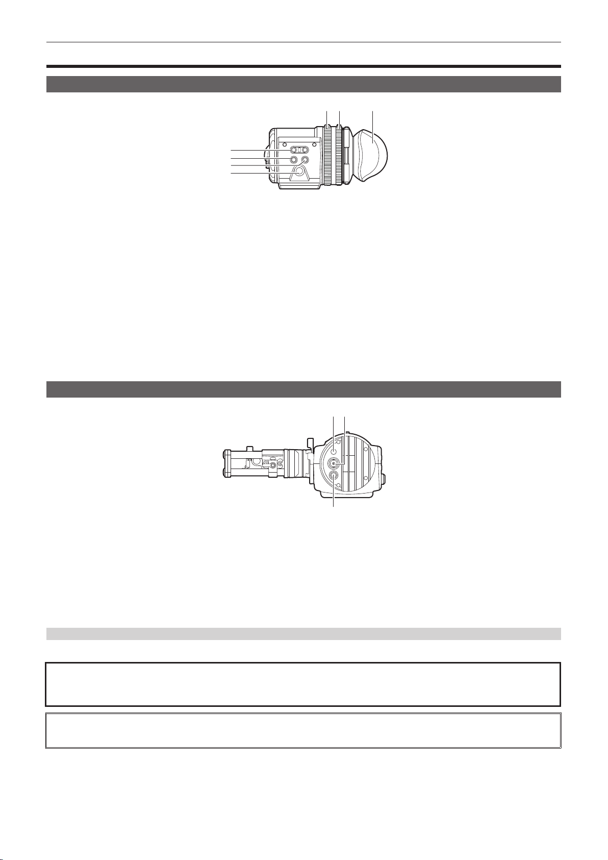
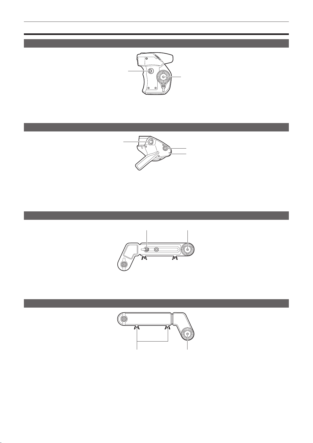
Electronic HD color view nder
Left side
5 6
1
2
3
4
1 <EVF USER 1>/<EVF USER 2> buttons
User-selected functions can be assigned to each button. Pressing a button performs the assigned function. Functions are set on the viewnder
menu.
2 <CAM MENU> button
Displays the camera menu screen.
3 <EVF MENU> button
Displays the viewnder menu screen.
4 Jog dial
Operation dial.
Used for setting, moving, and selecting in menus.
5 Zoom ring
Ring which enlarges/reduces the size of the viewnder display screen.
This is used to enlarge the display when adjusting the focus. When the display is enlarged, some parts of the video may be hidden.
6 Visibility adjustment ring
Ring which adjusts the visibility. Turn this ring while pressing and holding the upper button.
7 Eye cup
7
Front
132
1 Tally LED
Lights up in red during recording. This can be disabled in the viewnder menu.
2 Video signal input terminal
An input terminal for 3G/HD-SDI video signal input.
Use the supplied BNC cable or the 5C-FB equivalent double-shielded cable for the cable to connect to this terminal.
3 <DC IN 12V> terminal
An input terminal for power supply input.
Connect to the electronic HD color view nder power supply terminal on the camera.
Use the supplied DC cable when connecting a cable to this terminal.
Using the external DC power supply
To use it by itself, connect the <DC IN 12V> terminal of the camera to the external DC power supply.
r External DC power supply
Connect after making sure that the output voltage of the external DC power supply is compatible with the rated voltage of the camera.
When the power of the camera is turned on, inrush current is generated. Insufcient power supply when turning on the power may cause a malfunction. Use of
the external DC power supply that can secure power more than twice the total power consumption of the camera is recommended.
f Make sure of the pin alignment of the DC output terminal of the external DC power supply and the camera <DC IN 12V> terminal, and connect the polarity
correctly.
Connecting the GND terminal to +12 V power supply by mistake may cause re or malfunction.
– 14 –
Chapter 2 Description of Parts — Electronic HD color view nder
DC IN
1 GND
1
4
23
2 Data communication (from the viewnder to the camera body)
3 Data communication (from the camera body to the viewnder)
4
Cable connector
HR10A-7R-4SC (73) (Hirose Electric Co.)
+12 V
Rear
1 2
3 4
1 Eye sensor
Screen is displayed on the viewnder when an eye is brought close.
The eye sensor may not work properly depending on the shape of glasses in use, how you hold the camera, or the strong light hitting around the eye
piece.
2 Lock lever
Secures the viewnder in place.
3 Eye piece lter
Protective lter against dust, water, and moisture. Use the camera with this attached.
4 Stopper
Used when removing the viewnder from the slider unit.
Top
1 Lock lever (left/right position)
Adjusts the position of the viewnder (left/right).
2 Lock lever (front/back position)
Adjusts the position of the viewnder (front/back).
2
1
– 15 –
Chapter 2 Description of Parts — Shoulder mount module
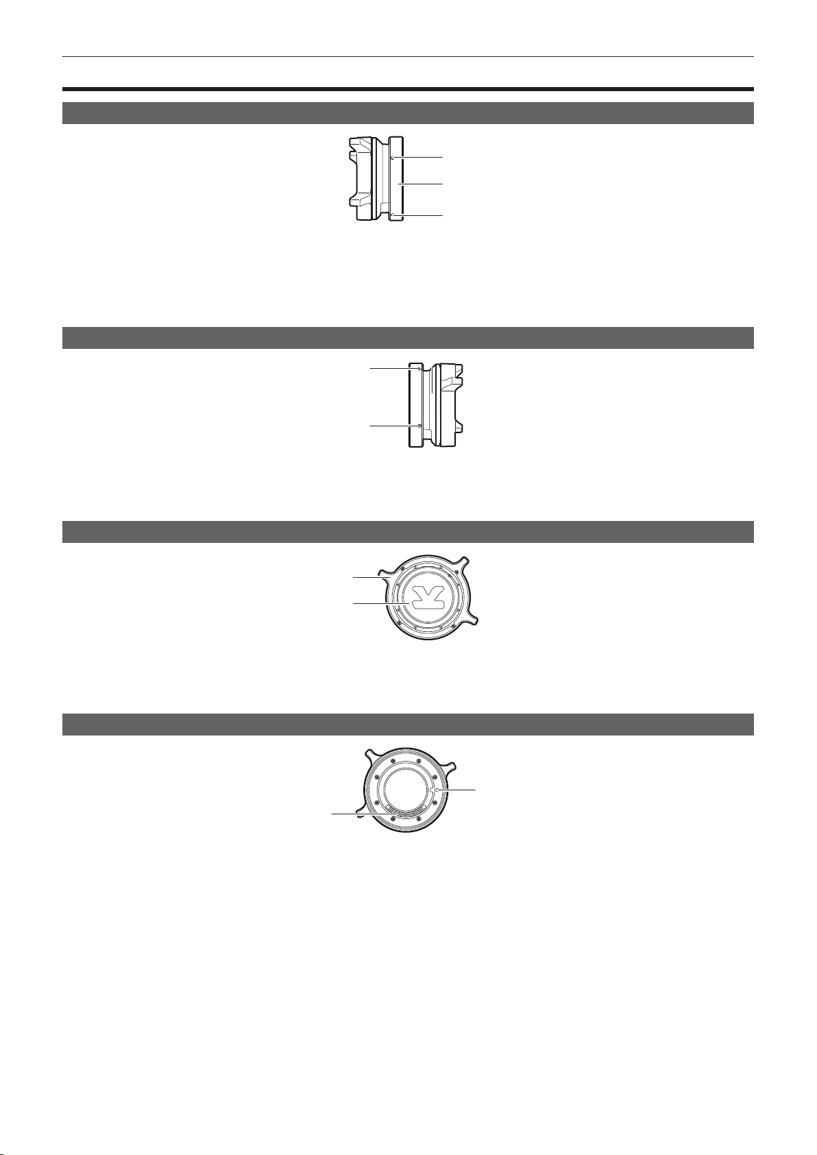
Shoulder mount module
Left side
1
2
3
1 Support rod lock knob
Secures the rod in place.
2 Accessory attachment (rosette)
For attaching accessories.
f Mounting screw size
- M6 (screw length 9 mm or shorter)
3 Stopper
Pressed when removing the slide rail from the shoulder mount module.
Right side
1
2
1 Support rod lock knob
Secures the rod in place.
2 Accessory attachment (rosette)
Attaches an accessory such as the dedicated grip module.
f Mounting screw size
- M6 (screw length 9 mm or shorter)
3 Slide rail lock knob
Secures the slide rail in place.
Front
1 Support rod mounting holes
Holes for connecting a rod with a diameter of 15 mm.
Rear
1 Support rod mounting holes
Holes for connecting a rod with a diameter of 15 mm.
3
1
1
Top
1 Slide rail
Attaches to the camera.
1
– 16 –
Chapter 2 Description of Parts — Grip module
Grip module
Left side
1
2
1 <USER GRIP2> button
The function that user has selected can be assigned. Pressing a button performs the assigned function.
2 Arm mounting section
For attaching an arm.
Top
1
2
3
1 <REC> button
Press this button to start recording. Press this button again to stop recording.
2 <USER GRIP1> button
The function that user has selected can be assigned. Pressing a button performs the assigned function.
3 <IRIS> dial
Controls the iris of the EF lens.
Left side (grip arm)
1
1 Arm xing knob
Fixes after adjusting the length of the arm.
2 Shoulder mount module mounting section
For attaching a shoulder mount module.
2
Right side (grip arm)
1 Cable clamp
A clamp for xing the cable.
2 Grip module mounting section
For attaching a grip module.
1
2
– 17 –
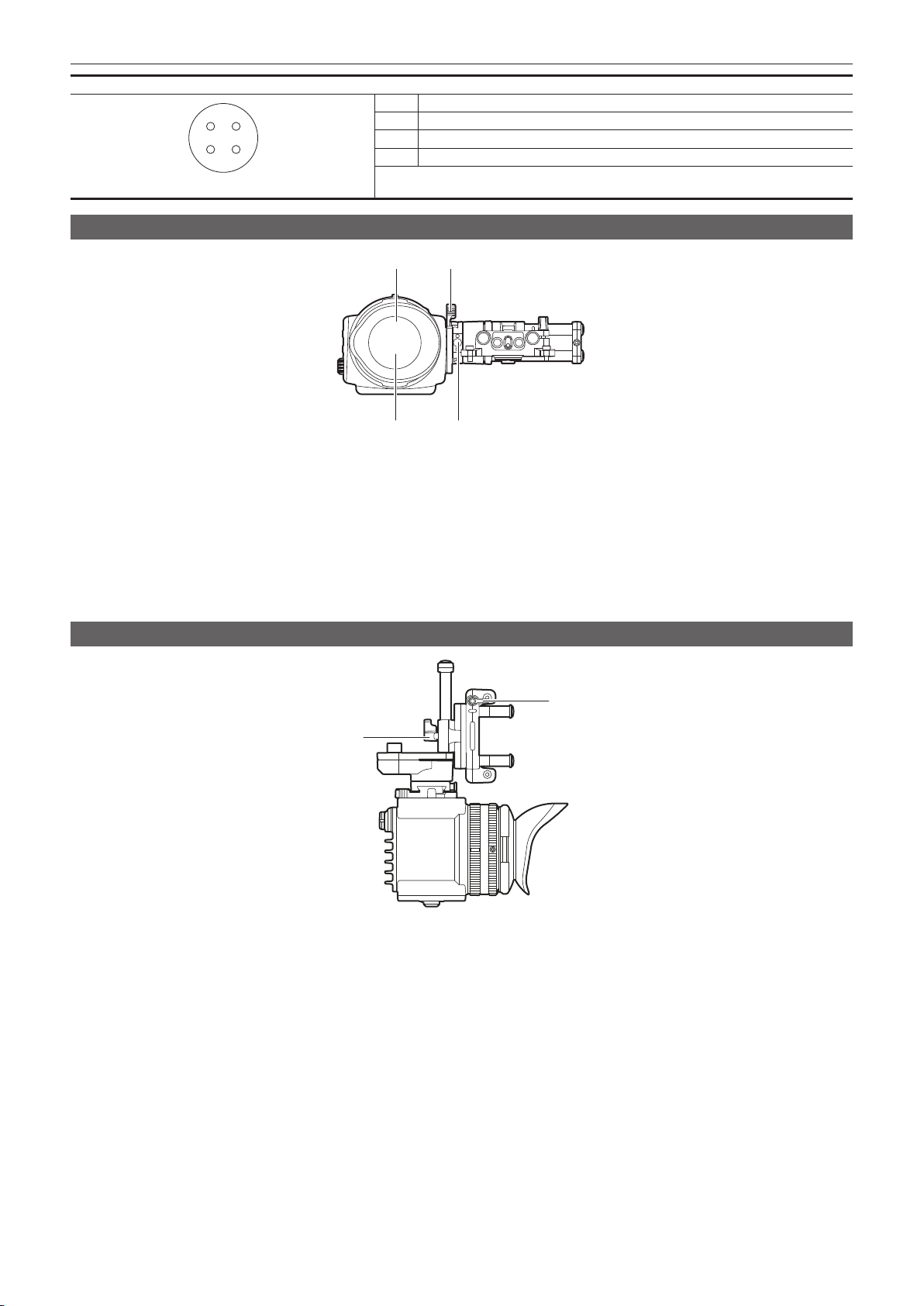
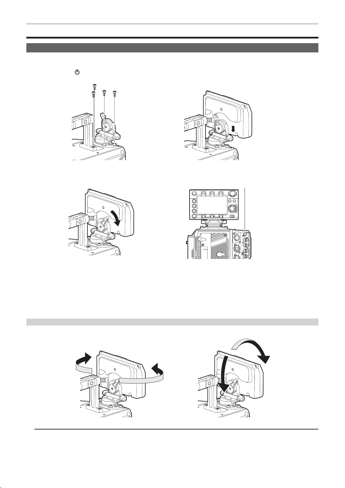
Chapter 2 Description of Parts — PL lens mount module
PL lens mount module
Left side
1 Mounting screw
The screw to x the PL lens mount module to the camera.
2 Mount xing ring
Fixes the PL lens mount module to the camera.
3 Tightening hole
The mount xing ring can be tightened using an Allen wrench.
Right side
1
2
3
1
2
1 Tightening hole
The mount xing ring can be tightened using an Allen wrench.
2 Mounting screw
The screw to x the PL lens mount module to the camera.
Front
1
2
1 Lens xing ring
Fixes the lens by turning the ring after mounting the lens to the lens mount.
2 Mount cap
Attaches the cap when the lens is not mounted.
Rear
1
1 Positioning hole
Align with the positioning pin on the camera.
2 Contact
Align with the connector of the camera.
2
– 18 –

Chapter 3 Preparation
Attach the module following the procedure in this chapter before using. The mounting of accessories is also described in this chapter.
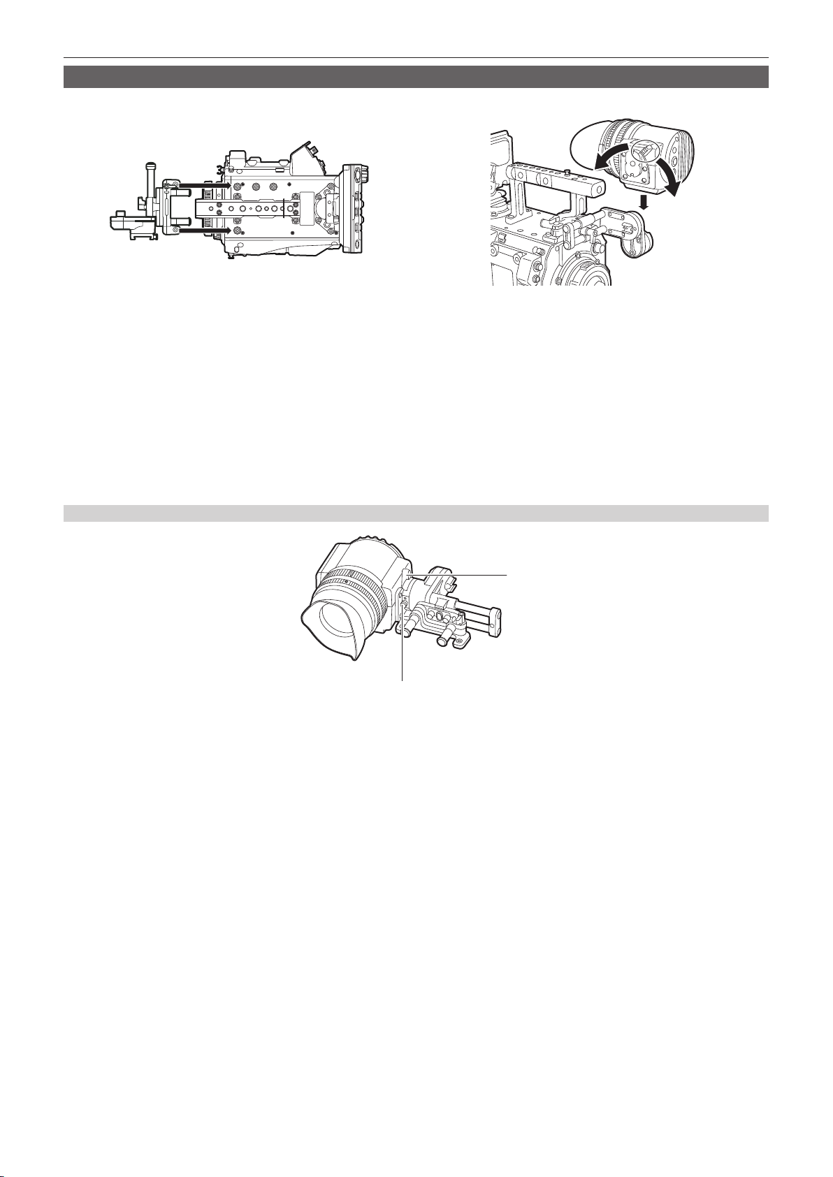
Chapter 3 Preparation — Mounting the module
Mounting the module
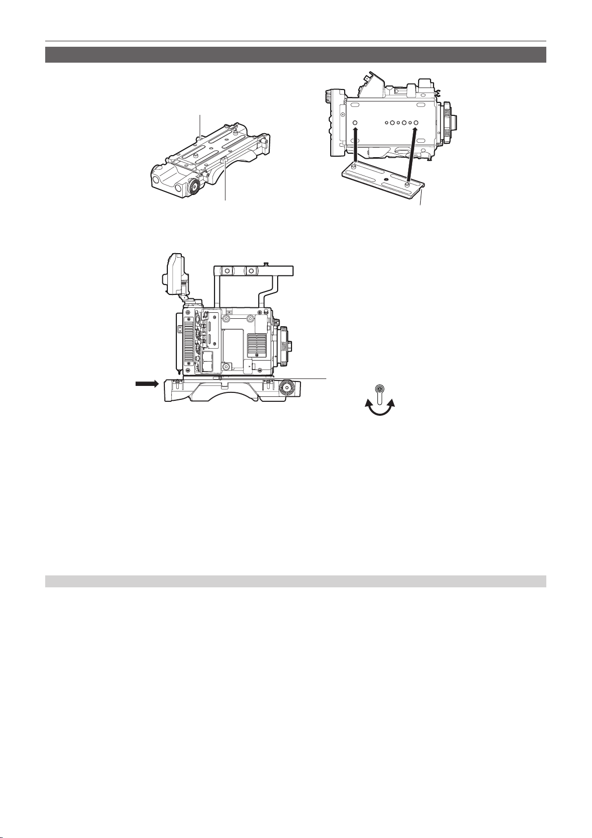
Mounting the control panel
The control panel is used by connecting the control panel cable to the <CONTROL PANEL> terminal at the rear of the camera.
Normal operation may not be possible when the control panel is mounted or removed while the power is turned on.
Set the power switch to <
It can be mounted to the rear of the camera using the supplied dedicated mounting part.
> when mounting or removing the control panel.
Fig. 1
Fig. 3 Fig. 4
Mount the control panel mounting part using the four supplied screws. (Fig. 1)
1
Mount the control panel onto the control panel mounting part. (Fig. 2)
2
Push down the lock lever to the right to lock. (Fig. 3)
3
Connect the cable of the control panel to the <CONTROL PANEL> terminal. (Fig. 4)
4
Panning operation/tilting operation
The angle or the tilt of the control panel can be adjusted.
Fig. 2
<CONTROL PANEL> terminal
NOTE
@@
t Use the cable clamp to prevent the cable from getting snagged.
– 20 –
Chapter 3 Preparation — Mounting the module
Mounting the electronic HD color view nder
Lock
Release
Fig. 1
Attach the slider unit to the viewfinder mounting holes on top of the camera using the two supplied screws. (Fig. 1)
1
Slide the viewfinder plate from above into the slider unit. (Fig. 2)
2
Release the viewnder lock lever by pushing it forward.
Push down the lock lever backwards to lock.
3
Connect the BNC cable supplied with the viewfinder to the video signal input terminal of the viewfinder and the <VF SDI> terminal
4
of the camera.
Connect the DC cable supplied with the viewfinder to the power supply input terminal of the viewfinder and the <DC OUT>
5
terminal of the camera.
Disassembling
b
a
Fig. 2
a: Stopper
b: Lock lever
Remove the connecting cable.
1
Push down the lock lever towards the front to release the lock.
2
Lift the viewfinder while pulling the stopper.
3
Remove the slider unit clamping screw.
4
– 21 –
Chapter 3 Preparation — Mounting the module
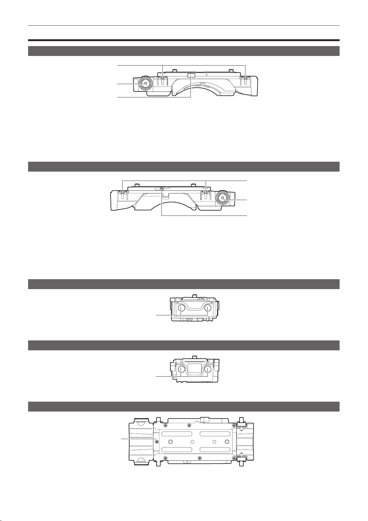
Mounting the shoulder mount module
Slide rail lock knob
Stopper
Fig. 1 Fig. 2
Slide rail lock knob
Lock Release
Fig. 3
Release the slide rail lock knob.
1
The angle of the slide rail lock knob can be changed by pulling and then turning.
Remove the slide rail from the shoulder mount module while pressing the stopper. (Fig. 1)
2
Orient the stopper opening of the slide rail toward the front of the camera, and securely mount to the bottom of the camera with
3
the supplied two screws on the screw holes indicated in the figure. (Fig. 2)
Stopper opening
Slide the camera forward along the groove in the shoulder mount module from the rear until it clicks. (Fig. 3)
4
Before mounting, conrm that the slide rail lock knob is released.
After adjusting the slide position of the camera considering its weight balance, lock by turning the slide rail lock knob clockwise.
5
Conrm that the camera is securely locked. The camera may fall causing a malfunction or injury when the camera is off balance or the screws are
not locked securely.
Disassembling
Release the slide rail lock knob.
1
The angle of the slide rail lock knob can be changed by pulling and then turning.
Remove the camera from the shoulder mount module by sliding it toward rear while pressing the stopper.
2
Loosen the two screws and remove the slide rail from the bottom of the camera.
3
If the shoulder mount is mounted on a tripod, lock the pan lock lever and the tilt lock lever of the tripod. It may lose balance and fall, causing a
malfunction or injury.
– 22 –
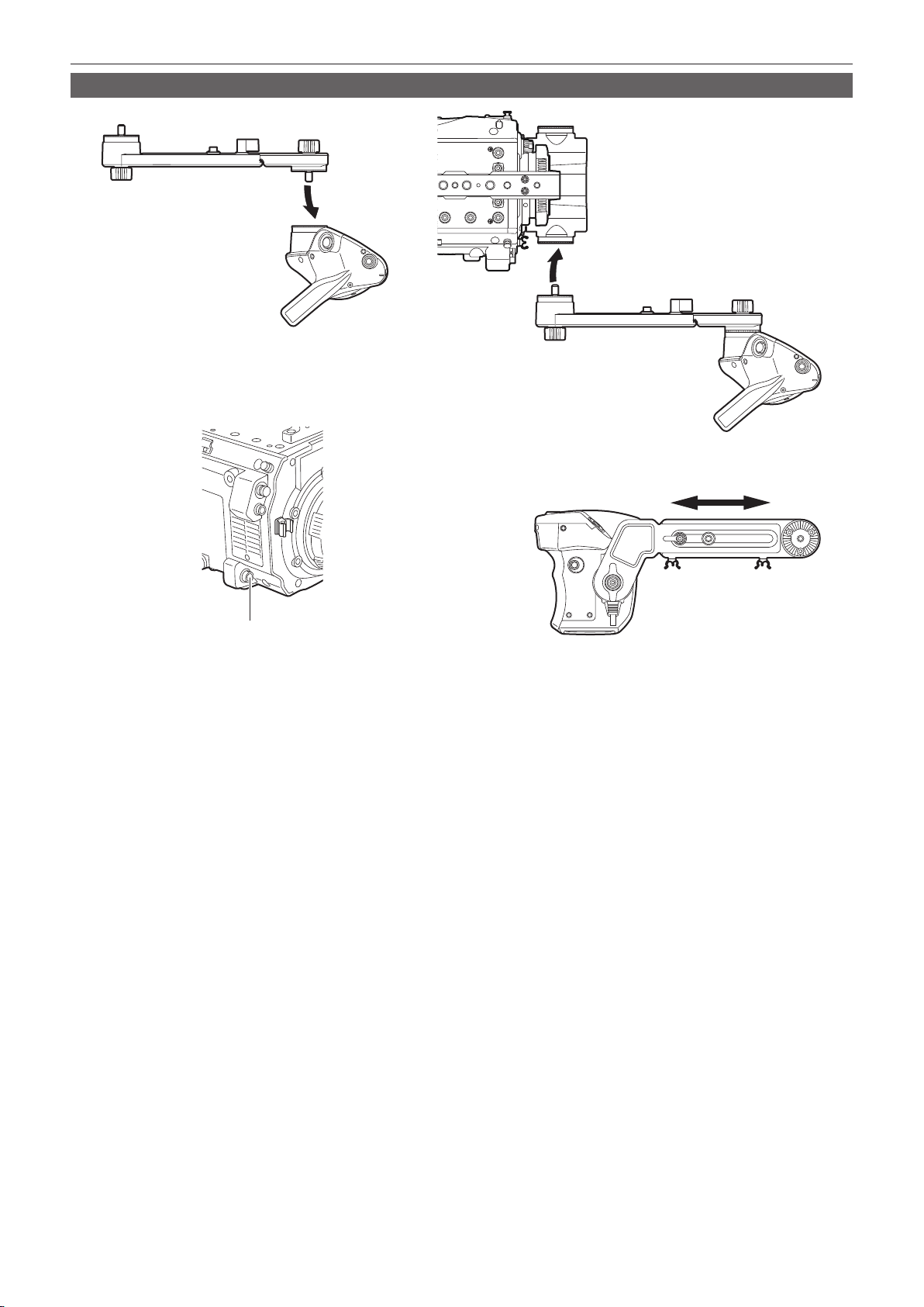
Mounting the grip module
Fig. 1
Chapter 3 Preparation — Mounting the module
Fig. 2
<LENS/GRIP> terminal
Fig. 3 Fig. 4
Attach the grip arm to the grip. (Fig. 1)
1
Attach the grip arm to the accessory attachment (rosette) on the shoulder mount module. (Fig. 2)
2
Connect the cable to the <LENS/GRIP> terminal. (Fig. 3)
3
Adjust the length of the grip arm. (Fig. 4)
4
Adjust the angle of the grip as necessary.
– 23 –
Chapter 3 Preparation — Attaching and removing accessories
Attaching and removing accessories
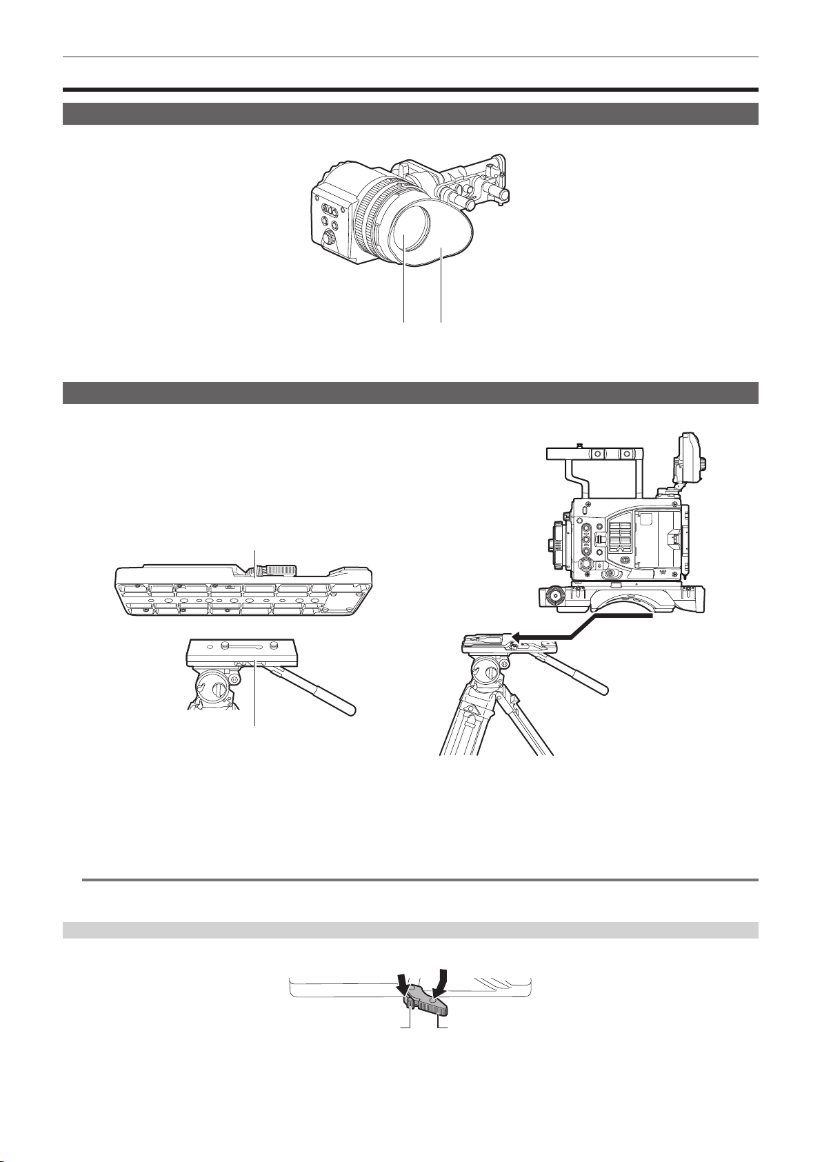
Eye cup/eye piece lter
The eye cup and eye piece lter can be removed. Always use the camera with these attached.
b a
a: Eye cup
b: Eye piece lter
Attaching a tripod
When mounting the camera on a tripod, use the optional tripod adaptor (SHAN-TM700).
Tripod adaptor
Pan head
Fig. 1 Fig. 2
Mount the tripod adaptor on the tripod. (Fig. 1)
1
Mount the camera on the tripod adaptor. (Fig. 2)
2
Slide the camera forward along the grooves until you hear a click.
NOTE
@@
t Select an appropriate hole in the adaptor, taking into account the center of gravity of the camera and tripod adaptor combined.
Also, make sure that the diameter of the selected hole matches the diameter of the pan head screw.
Removing the camera from the tripod adaptor
While holding the red lever down, move the black lever in the direction of the arrow, and slide the camera backward to remove it.
Red lever Black lever
– 24 –

Chapter 3 Preparation — Attaching and removing accessories
NOTE
@@
t If the tripod adaptor pin does not return to its original position after the camera has been removed, hold the red lever down and move the black lever in
the direction of the arrow again, in order to return the pin to its original position.
The camera cannot be mounted if the pin remains in the center. Be careful.
Rain cover
A rain cover SHAN-RC700 (optional) can be attached.
– 25 –
Chapter 3 Preparation — Power supply
Power supply
A battery or an external DC power supply can be used as the power supply.
Using batteries
Connection of the following batteries to the camera has been veried.
r Anton/Bauer batteries
HYTRON140
DIONIC HC/DIONIC HCX/DIONIC HD
r IDX batteries
ENDURA HL9
NOTE
@@
t Other battery can be supported by changing [- BATTERY SELECT] in [MENU] → [SYSTEM SETTINGS] → [POWER MANAGEMENT]. It is
recommended to use the battery that is veried to be connected with the camera.
t Before you use a battery, charge it with a battery charger. (For details on charging, refer to each operating instructions.)
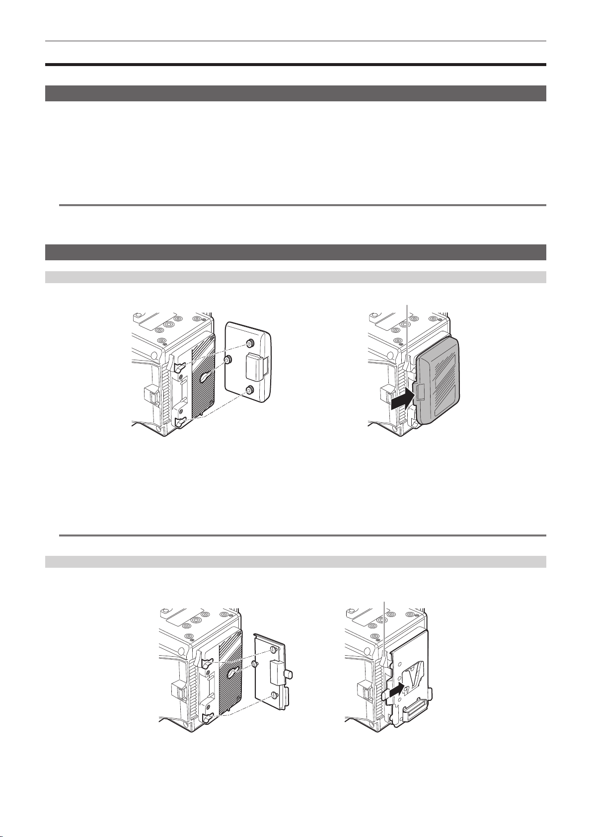
Mounting and setting battery
Using Anton/Bauer batteries
Release lever
Anton/Bauer batteries
Mount the Anton/Bauer battery.
1
Insert the battery terminal and slide in the direction of the arrow.
2
Set the battery type.
3
Select the type of the battery in [MENU] → [SYSTEM SETTINGS] → [POWER MANAGEMENT] → [- BATTERY SELECT].
For details, refer to “Setting menu basic operations” (page 109).
NOTE
@@
t To remove the battery, keep the release lever of the battery holder completely down, slide the battery in the opposite direction when you mounted it.
Using V-mount type batteries
Mount the V-mount type battery plate. As shown in the illustration, insert and slide in the direction of the arrow.
Release lever
Mount the V-mount type battery plate.
1
Slide in the direction of the arrow.
2
Set the battery type.
3
– 26 –
Chapter 3 Preparation — Power supply
f Set the type of the battery in [MENU] → [SYSTEM SETTINGS] → [POWER MANAGEMENT] → [- BATTERY SELECT].
NOTE
@@
t Contact your dealer for information about the V-mount type battery plate.
t When the V-mount type battery plate is used, % (percent) is not displayed even if batteries with a battery level indicator function are used.
t When removing the plate, remove by sliding the release lever.
t When using a battery that is not included in [- BATTERY SELECT], set [other], then set [- FULL VOLT], [- NEAR END VOLT], or [- END VOLT]
according to the characteristics of the battery.
Using the external DC power supply
<DC IN> terminal
DC cable
Connect the external DC power supply to the <DC IN> terminal of the camera.
1
Turn on the power switch of the external DC power supply (if the external DC power supply has a power switch).
2
Turn the power switch of the camera to <l>.
3
r External DC power supply
Connect after making sure that the output voltage of the external DC power supply is compatible with the rated voltage of the camera.
Select an output amperage for the external DC power supply with a margin above the total amperage of the connected devices.
The total amperage of connected devices can be calculated with the following formula.
Total power consumption ÷ Voltage
When the power of the camera is turned on, inrush current is generated. Insufcient power supply when turning on the power may cause a malfunction. We
recommend that you use an external DC power supply that can assure double the capacity of the total power consumption of the camera and connected devices
that are turned on by interlock when the power of the camera is turned on (such as lenses). For the DC cable, use a dual-core shielded wire of AWG16 (nominal
cross section area 1.309 mm
f Make sure of the pin alignment of the DC output terminal of the external DC power supply and the camera <DC IN> terminal, and connect the polarity
correctly.
If the +12 V power supply is mistakenly connected to the GND terminal, it may cause re or malfunction.
2
) or thicker.
DC IN
1 GND
2 NC
3 NC
4
Manufacturer Parts No.: HA16RX-4P (SW1) (76) (Hirose Electric Co.)
External DC power supply
+12 V
Panasonic Parts No.: K1AA104H0038
NOTE
@@
t When both the battery and the external DC power supply are connected, the power supply from the external DC power supply has priority. The battery
may be removed while using the external DC power supply.
t When using the external DC power supply, always turn on the power switch of the external DC power supply before setting the power switch of the
camera to <l>. If the operations are performed in reverse, the camera may malfunction because the external DC power supply output voltage rises too
slowly.
t When switching the power supply from an external DC power supply to the battery, carefully remove the DC cable from the <DC IN> terminal.
Removing the cable quickly may temporarily stop the camera’s operation.
t When power is supplied from the <DC IN> terminal, the light circuit does not function. The light circuit can be used only when power is supplied from
the Anton/Bauer battery plate.
t When connecting a battery to the <DC IN> terminal, set [MENU] → [SYSTEM SETTINGS] → [POWER MANAGEMENT] → [DC IN SOURCE] to
[BATTERY], then set [- FULL VOLT], [- NEAR END VOLT], or [- END VOLT] to match the characteristics of the battery. However, in this the case, the
percent (%) display will not be available for batteries with a battery level indicator function.
– 27 –

Chapter 3 Preparation — Power supply
Switching between external DC power supply and battery power supply
Status for both the battery power supply and the external DC power supply are monitored within the camera. Status of each power supply can be
conrmed in the control panel and the indicator. (page 67)
The external DC power supply is prioritized. It will automatically switch to the battery power supply when both the battery power supply and the external
DC power supply are connected and the indicator on the side of the external DC power supply goes under the remaining charge level near end is
displayed.
Once it is switched, the voltage display will display slightly higher voltage value due to less load on the external DC power supply.
It will be as follows when the external DC power supply is connected when only the battery power supply is in use.
f It will continue to use the battery power supply when the indicator on the side of the external DC power supply is displaying the remaining charge level
near end.
f It will switch to the external DC power supply when the indicator on the side of the external DC power supply is displayed with the power supply
voltage.
– 28 –
Chapter 3 Preparation — Mounting and adjusting the lens
Mounting and adjusting the lens
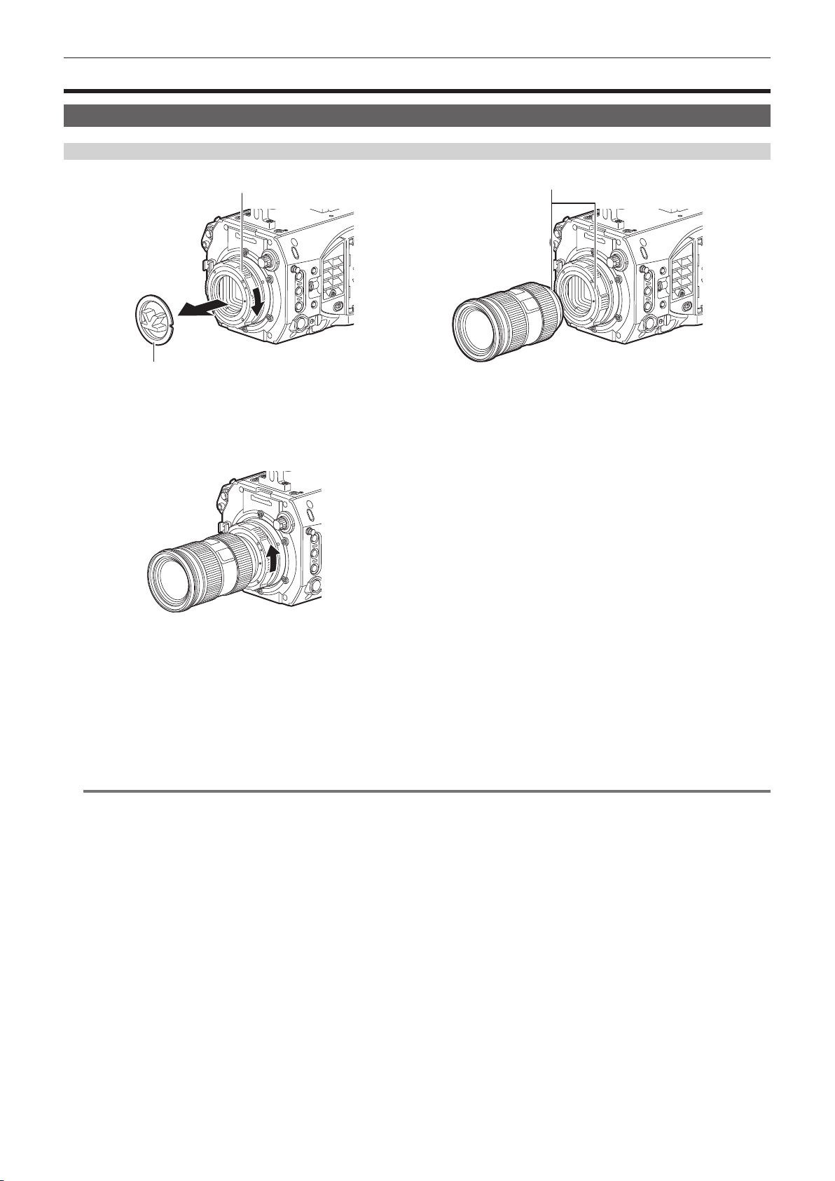
EF lens
Mounting the lens
Mount cap
Lens fixing ring
Fig. 1 Fig. 2
Marks
Fig. 3
Turn the lens fixing ring and remove the mount cap. (Fig. 1)
1
Align the mark (red circle) on the lens mount with the mark (red circle) on the lens, and mount the lens. (Fig. 2)
2
Turn the lens fixing ring to securely fix the lens. (Fig. 3)
3
Set [MENU] → [CAMERA SETTINGS] → [LENS SETTING] → [LENS CONNECT TYPE] to [EF].
4
NOTE
@@
t For handling the lens, refer to the lens operating instructions.
t When the lens is removed, install the mount cap to protect the device.
– 29 –
Chapter 3 Preparation — Mounting and adjusting the lens
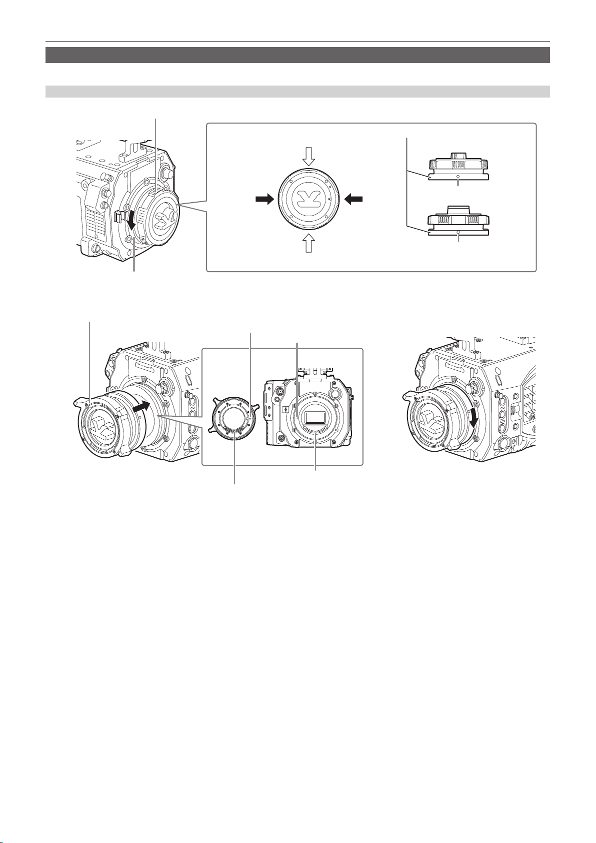
PL lens
The PL lens can be used by replacing the lens mount.
Replacing the lens mount
EF mount
Mount fixing ring
PL lens mount module
Fig. 1
Mounting
screw
Positioning hole
Tightening hole
Tightening hole
Positioning pin
Mount fixing ring
Mounting screw
(Round hole, 2 locations)
Mounting
screw
Tightening hole
(4 mm hexagon hole, 2 locations)
Fig. 2
Contact
Loosen the two mounting screws on the mount fixing ring. (Fig. 1)
1
f Use the 1.5 mm Allen wrench.
f The position of the mounting screw may not match with the illustration depending on the xing condition of the mount.
Turn the mount fixing ring to remove the EF mount. (Fig. 1)
2
f If the xing ring is stiff and does not turn, insert an Allen wrench into the tightening hole on the xing ring and turn the xing ring.
Attach the PL lens mount module. (Fig. 2)
3
f Align the positioning pin and the positioning hole. Also align the connector on the camera with the contact on the mount.
Turn the mount fixing ring to fix. (Fig. 3)
4
Fix the two mounting screws. (Fig. 1)
5
Connector
Fig. 3
– 30 –
 Loading...