

Page 1

35
Operating Guide
W1014HM0 -YI VQT5K88A(E)
Page 2

f SDXC logo is a trademark of SD-3C, LLC.
f MMC (Multi Media Card) is a registered trademark of Inneon Technologies AG.
f Microsoft
f Screenshots are used according to Microsoft Corporation guidelines.
f Apple, Macintosh, Mac OS, QuickTime, iPad, and iPhone are trademarks or registered trademarks of Apple Inc. in the United States and/or other
countries.
f Java and all Java-based trademarks are trademarks or registered trademarks of Sun Microsystems, Inc. in the United States.
f All other names, company names, product names, etc., contained in this document are trademarks or registered trademarks of their respective
owners.
f This product is licensed under the AVC Patent Portfolio License. All other acts are not licensed except private use for personal and non-prot purposes
such as what are described below.
f Use of DCF Technologies under license from Multi-Format, Inc.
®
and Windows® are registered trademarks or trademarks of Microsoft Corporation in the United States and/or other countries.
- To record video in compliance with the AVC standard (AVC Video)
- To play back AVC Video that was recorded by a consumer engaged in a personal and non-commercial activity
- To play back AVC Video that was obtained from a video provider licensed to provide the video
Visit the MPEG LA, LLC website (http://www.mpegla.com/) for details.
How to read this document
r Illustrations
f Screenshots or illustrations may differ from the actual product.
r Conventions used in this manual
f Words and phrases in [ ] brackets indicate details and content displayed in the viewnder or control panel.
f Words and phrases in < > brackets indicate design text used on this camera, such as button names.
r Reference pages
f Reference pages in this document are indicated by (page 00).
r Terminology
f SD memory card, SDHC memory card, and SDXC memory card are referred to as “SD memory card”.
f A memory card with the “P2” logo such as AJ-P2E064FG memory card (optional) is referred to as a “P2 memory card”.
f A memory card with the “microP2” logo such as AJ-P2M032AG memory card (optional) is referred to as a “microP2 memory card”.
f A memory card with the “expressP2” logo such as AU-XP0256AG memory card (optional) is referred to as a “expressP2 memory card”.
f P2 memory card, microP2 memory card, and expressP2 memory card are referred to only as “P2 card” unless distinguished otherwise.
f Video that is created during a single recording operation is referred to as a “clip”.
– 2 –
Page 3

Contents
Contents
Chapter 1 Overview 5
Before using the camera 6
Accessories 8
Camera module 8
Recording module 8
Electronic HD color viewnder 8
Shoulder mount module 8
Use of the camera on a system 9
Basic system devices 9
Expansion system devices 9
Accessories 9
Chapter 2 Description of Parts 10
Camera module 11
Left side 11
Right side 11
Front 12
Rear 13
Top 13
Bottom 13
Recording module 14
Left side 14
Right side 1 5
Front 1 5
Rear 1 6
Top side 16
Bottom
17
Electronic HD color viewnder 18
Left side 18
Front 18
Rear 18
Top 19
Shoulder mount module 20
Left side 20
Right side 2 0
Front 2 0
Top 2 0
Chapter 3 Preparation 21
Assembling modules 22
Assembling the camera module and recording module 22
Mounting the Electronic HD color viewnder 23
Mounting the shoulder mount module 2 4
Attaching and removing accessories 25
Eye cup/eye piece lter 2 5
Attaching a tripod 25
Attaching the rain cover 2 6
Power supply 27
Using batteries 27
Mounting and setting battery 27
Using external DC power supply 28
Mounting and adjusting the lens 29
Mounting the lens 29
Flange lens back adjustment 29
Connecting to the DC output terminal 30
Connecting the <DC OUT/RS> terminal to the external
recording start/stop switch 30
Connecting to the <DC OUT> terminal 3 0
Setting the date/time of the internal clock 31
Formatting a P2 card 4 0
Special recording functions 41
Hot swap recording 4 1
Shot mark recording function 4 1
Text memo recording function 4 1
Chapter 5 Control Panel 42
Control panel operation 43
Camera status display 4 3
Using the control panel extension unit 4 4
HOME screen 46
PLAY screen 48
TC screen 49
INFO screen 50
VIEW screen 51
MENU screen 52
Chapter 6 Audio recording 53
Preparing for audio input 54
Using front microphone 5 4
Using audio devices 55
Selecting audio input and adjusting recording levels 56
Selecting audio input signals 56
Adjusting the recording levels 56
Audio monitor (headphones) 5 7
Chapter 7 Viewnder 58
Adjusting and setting the viewnder 59
Adjustment method 5 9
Viewnder status display 60
Lamp display 60
Status display 60
Convenient shooting functions 63
Zebra patterns display 6 3
Displaying the center marker 63
Displaying the safety zone marker 6 3
Displaying frame marker 6 3
Focus assist function 6 3
Chapter 8 Output and Screen Display 65
SDI output 66
Output format list 66
<MON OUT1> output 68
Output format list 68
<MON OUT2> output 69
Output format list 69
<VF SDI> output 70
Output format list 70
Screen status display 71
Status display (STATUS) in the <MON OUT1>, <MON
OUT2>, and <VF SDI> outputs. 71
Control panel status display (VIEW screen) 72
Chapter 9 Other Useful Functions 73
Getting position information using the GPS 74
Assigning functions to the USER buttons 75
Selectable functions 75
Handling setting data 76
Chapter 4 Video Recording and Color Grading 32
Dual-recording 33
Selecting the resolution, codec, and video format for
recording 34
In-camera grading 35
Grading function 3 5
Control combinations through settings 3 5
P2 card 36
Inserting a P2 card 3 6
Removing a P2 card 37
Preventing accidental erasure 37
Card access LEDs and P2 card status 37
P2 card recording time 38
CPS (Content Protection System) 38
How to handle data recorded on P2 cards 39
Handling SD memory cards 7 6
Performing operations on SD memory cards 7 6
Setting the time data 77
Denition of time data 77
User bits settings 77
How to input user bits 77
Setting the time code 78
Externally locking the time code 78
Supplying the time code externally 79
Chapter 10 Menu Operations 81
Setting menu structure 82
Menu conguration 82
Setting menu display 83
Setting menu basic operations 83
– 3 –
Page 4

Contents
Setting menu initialization 83
Menu list 84
[SYSTEM SETTINGS] 84
[CAMERA SETTINGS] 91
[REC SETTINGS] 95
[VF SDI SETTINGS] 96
[PERIPHERAL] 98
Menu operations 99
[SYSTEM SETTINGS] 99
[CAMERA SETTINGS] 101
[REC SETTINGS] 103
[VF SDI SETTINGS] 103
[PERIPHERAL] 104
Chapter 11 Maintenance and Inspection 105
Inspections before shooting 106
Maintenance 107
Charging the built-in battery 107
Warning system 108
Cases indicated by error codes 108
Cases indicated by error messages 108
Updating the camera rmware 111
Updating the rmware 111
Cleaning and storing 112
Cleaning the camera recorder 112
Cautions when storing the camera recorder 112
Chapter 12 Specication 113
Specications 114
Dimensions 11 4
Specications 11 4
Index 117
– 4 –
Page 5

Chapter 1 Overview
Before using the camera, read this chapter.
Page 6

Chapter 1 Overview — Before using the camera
Before using the camera
r When using this product during rain or snow or when at the beach, be careful that water does not get inside the camera recorder.
Water causes damage to the camera recorder and memory card. (Repair may be impossible)
r Keep the camera recorder away from devices (TVs, TV games, etc.) that produce magnetism.
f If you use the camera recorder near TVs, video and sound data may be distorted by electromagnetic waves.
f Strong magnetic elds produced by speakers and large motors may cause damage to recorded contents and may distort images.
f Electromagnetic waves emitted by microcomputers may have a harmful effect on the camera recorder and may corrupt video and sound data.
f The camera recorder may not operate properly if it receives harmful effects from devices that produce magnetism. In this case, turn off the camera
recorder, and remove the battery. Next, attach the battery again. After that, turn on the camera recorder.
r Do not use the camera recorder near radio transmitters or high-voltage devices.
If you use the camera recorder near radio transmitters or high-voltage devices, the recorded video and sound data may suffer harmful effects.
r When using the camera recorder at the beach, etc., be careful that sand and dust do not get inside the camera recorder.
Sand and dust may damage the camera recorder and memory card. (Be careful when inserting and removing the memory card)
r When carrying the camera recorder, be careful not to drop it.
f Strong shocks will damage the camera recorder body and it may not operate properly.
r Do not apply insecticide or volatile materials to the camera recorder.
f If insecticide or volatile materials come into contact with the camera recorder, the camera recorder body may warp and the paint may come off.
f Do not allow the camera recorder to remain in contact with rubber or vinyl objects for a long period of time.
r After using the camera recorder, be sure to remove the battery.
Be sure to remove the battery from the camera recorder. (If the battery is left in the camera recorder, it will continue to consume a small amount of
electric current even when the power is turned off)
If the battery is left inside the camera recorder for a long time, it will over discharge and may become unusable even if it is recharged.
Do not remove the battery when the power is turned on.
Turn off the power and remove the battery after the operation lamp goes completely out.
r Take proper care of the battery terminal.
Do not allow dust or foreign objects on the battery terminal.
Also, if you drop the battery by mistake, make sure that the battery body and the terminal are not warped.
Inserting a deformed battery into the camera recorder or attaching it to the battery charger may cause damages on the camera recorder or battery
charger.
r Cautions when throwing memory cards away or transferring them to others
Formatting memory cards or deleting data using the functions of the camera or a computer will merely change the le management information: it will
not completely erase the data on the cards. When throwing these cards away or transferring them to others, either physically destroy them or use a
data deletion program for computers (commercially available) to completely erase the data. Users are responsible for managing the data stored in their
memory cards.
r Control panel and viewnder
f If the same image or letters are allowed to be displayed on the control panel for a long time, the image may be burned into the screen. It will return to
normal after leaving the camera recorder turned off for several hours.
f Condensation sometimes forms on the LCD of the control panel in locations subject to extreme temperature differences. If this happens, wipe with a
soft, dry cloth.
f If the camera recorder is very cold, the control panel will be slightly darker than normal immediately after the power is turned on. It will return to its
regular brightness when the temperature inside increases.
f Since the viewnder uses organic EL, if the same image or letters are allowed to be displayed for a long time, the image may be burned into the
screen. There is no problem with the recorded images.
Switch the screen by turning off the screen or by using the eye sensor, etc.
f The control panel and viewnder monitor (organic EL) are highly-precisely managed so that at least 99.99% of the dots are effective pixels and 0.01%
or less are invalid pixels and always lit. This is not a malfunction and it has no effect whatsoever on the recorded images.
r Do not point the eye piece of the lens and viewnder at the sun.
Doing so might damage the components inside.
r GPS
GPS (Global Position System) satellite is managed by the United States Department of State and its precision is sometimes intentionally changed.
Position it in a location where there is a good view of the sky and there is no inuence of obstacles such as roofs and trees, etc.
Depending upon the surrounding environment and the time, it may take a long time to position and errors may be larger.
r Caution regarding laser beams
The MOS sensor may be damaged if the MOS sensor is subjected to light from a laser beam.
Take sufcient care to prevent laser beams from striking the lens when shooting in an environment where laser devices are used.
– 6 –
Page 7

Chapter 1 Overview — Before using the camera
r Note the following points.
f If you prepare to record important images, always shoot some advance test footage to verify that both pictures and sound are being recorded
normally.
f Should video or audio recording fail due to a malfunction of the camera or the P2 cards used, we will not assume liability for such failure.
f Set up or check the calendar and time zone before recording. (page 31) These settings have an effect on the management and playback order of
the recorded contents.
r Software information about this product
1 This product includes software licensed under GNU General Public License (GPL) and GNU Lesser General Public License (LGPL), and
customers are hereby notied that they have rights to obtain, re-engineer, and redistribute the source code of these software.
2 This product includes software licensed under MIT-License.
3 This product includes software developed by the OpenSSL Project for use in the OpenSSL Toolkit (http://www.openssl.org/).
4 This product includes software licensed under OpenBSD License.
5 This product includes PHP, freely available from <http://www.php.net/>.
6 This software is based in part on the work of the Independent JPEG Group.
7 This product includes software licensed under MOZILLA PUBLIC LICENSE.
For details on these descriptions (originally provided in English) and how to obtain the source code, visit the following website.
http://pro-av.panasonic.net/
We do not accept inquiries about the details of the source code obtained by the customer.
r Precautions when installing USB drivers
For the latest information on the driver, visit the following website.
http://pro-av.panasonic.net/
f Install the required driver into your computer from the website.
f For installation procedure of the driver, refer to the installation manual on the website.
– 7 –
Page 8

Chapter 1 Overview — Accessories
Accessories
Camera module
f Mount cap (already attached to the camera module)
Recording module
f Control panel extension unit
f Control panel mounting part
Electronic HD color viewnder
f Connecting cable
f Slider unit
f Slider unit mounting screw (2 pcs.)
f Eye cup (already attached to the Electronic HD color viewnder)
f Eye piece lter (already attached to the Electronic HD color viewnder)
Shoulder mount module
f Slide rail (already attached to the shoulder mount module)
NOTE
@@
t After unpacking the product, dispose of the packing material properly.
– 8 –
Page 9
Chapter 1 Overview — Use of the camera on a system
Use of the camera on a system
Use the following recommended parts.
Basic system devices
The following are required devices for shooting.
Part name Part No. Remark
VARICAM 35 Camera module*
Recording module*
Shoulder mount module AU-VSHL1G “Mounting the shoulder mount module” (page 24)
Electronic HD color viewnder AU-VCVF1G
Lens (35 mm, PL mount) ZEISS/COOKE/CANON/FUJINON, etc. “Mounting the lens” (page 29)
Stereo microphone kit AJ-MC900G “Using front microphone” (page 54)
Battery
expressP2 memory card AU-XP0256AG “P2 card” (page 36)
SD memory card*
P2 memory card*
microP2 memory card*
*1 The camera module and recording module are both required in this system. The system will not run with only one of those modules.
*2 A battery holder is provided as standard on the recording module.
*3 Refer to our support desk at the following website for the latest information not included in this document.
http://pro-av.panasonic.net/
1
3
3
1
3
AU-V35C1G
AU-VREC1G
DIONIC HD*
HYTRON140*
Visit the support desk at the website*
2
2
3
“Assembling the camera module and recording
module” (page 22)
“Assembling the camera module and recording
module” (page 22)
“Mounting the Electronic HD color viewnder”
(page 23)
“Mounting and setting battery” (page 27)
“P2 card” (page 36)
Expansion system devices
You can also use the following devices in addition to the basic system devices.
Part name Part No. Remark
4K LCD monitor BT-4LH310 —
LCD monitor BT-LH910G, etc. —
Memory card drive AU-XPD1 —
External DC power supply — “Using external DC power supply” (page 28)
VARICAM HS camera module AU-V23HS1G —
Accessories
Product name Model No. Remark
Tripod adaptor SHAN-TM700 “Attaching a tripod” (page 25)
Soft carrying case AJ-SC900 —
Rain cover SHAN-RC700 “Attaching the rain cover” (page 26)
Microphone holder AJ-MH800G “Using front microphone” (page 54)
– 9 –
Page 10

Chapter 2 Description of Parts
This chapter describes the names, functions, and operations of parts on the camera.
Page 11
Camera module
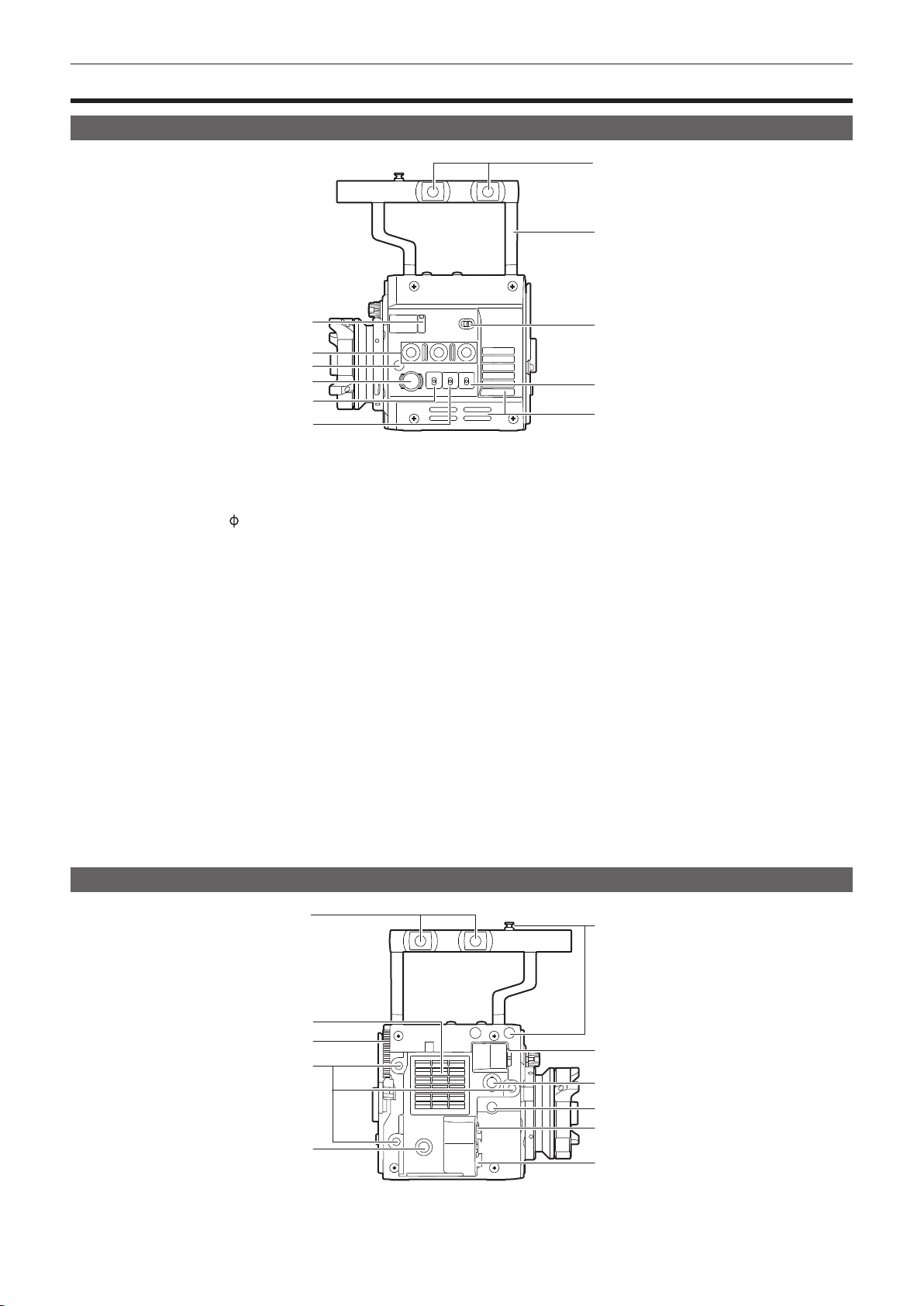
Left side
Chapter 2 Description of Parts — Camera module
7
8
1
2
3
4
5
6
1 Lens ange back adjustment hole
Used when adjusting the lens ange back.
2 USER buttons (<1>/<2>/<3>)
User-selected functions can be assigned to each button. Pressing a button performs the assigned function.
3 Focus hook/focus mark <
Indicate the focal plane of the MOS sensor.
4 <REC> button
Press this button to start recording. Press this button again to stop recording. The button lights up in red during recording.
5 <SHUTTER> switch
Switch for changing the electronic shutter.
6 <EI> switch
Switch for changing the EXPOSURE INDEX (gain).
7 Accessory mounting holes
For attaching accessories.
f Mounting hole size
- 3/8-16 UNC
8 Handle
9 <LOCK> switch
Disables the operation of the camera module buttons and switches. (except the <REC> button)
Keep this in the <LOCK> position to prevent incorrect operation when moving the camera, etc.
10 <WB> switch
Switch for changing the white balance.
11 Fan inlet
Fan inlet for dissipating heat. Do not block this when the camera is in use.
>
9
10
11
Right side
1 Accessory mounting holes
For attaching accessories.
f Mounting hole size
1
2
3
4
5
6
7
8
9
10
11
– 11 –
Page 12
Chapter 2 Description of Parts — Camera module
- 3/8-16 UNC
2 Fan outlet
Fan outlet for dissipating heat. Do not block this when the camera is in use.
3 Recording module release lever
Lever for removing the recording module (optional) from the camera module.
4 Accessory mounting holes
For attaching accessories.
f Mounting hole size
- 1/4-20 UNC (screw length 5.5 mm or shorter)
5 USER button (<4>)
User-selected functions can be assigned to this button. Pressing the button performs the assigned function.
6 Focus hook
Indicate the focal plane of the MOS sensor. It provides a reference for measuring the accurate focal length from the subject.
7 <VF> terminal
Terminal for connecting the HD viewnder AU-VCVF1G (optional).
8 <VF SDI> terminal
Output terminal for 3G/HD SDI. Displays the video equal to the viewnder display.
For the cable to connect to this terminal, prepare a double-shielded cable equivalent to 5C-FB.
9 <DC OUT> terminal
This is the DC12 V output terminal. It provides a maximum current of 1 A.
10 <MIC IN> terminal
Terminal for connecting a microphone.
11 <LENS> terminal
Terminal for connecting a lens cable. For details, refer to the Operating Instructions for the lens.
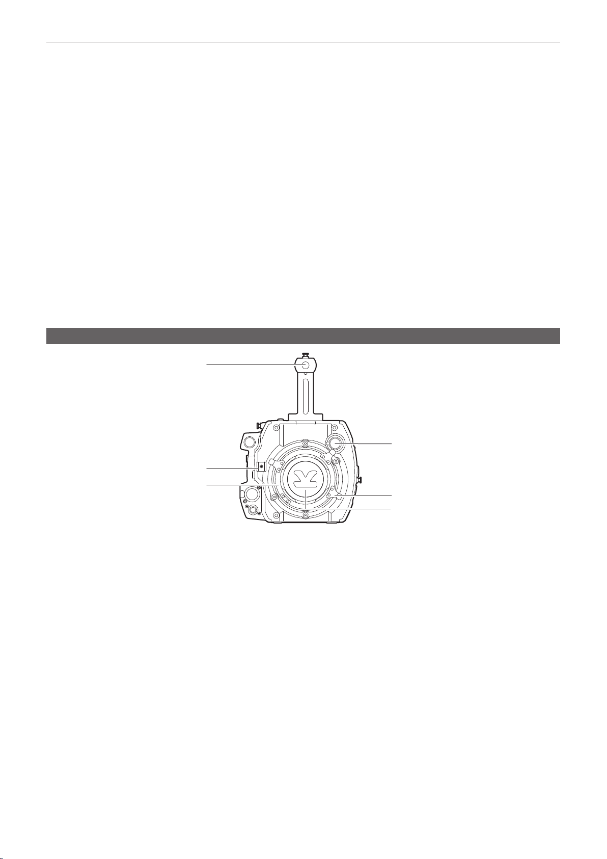
Front
1
2
3
1 Accessory mounting holes
For attaching accessories.
f Mounting hole size
- 3/8-16 UNC (screw length 5.5 mm or shorter)
2 Lens cable /microphone cable clamp
Clamp for securing the lens and microphone cables.
3 Lens mount
Holds the lens.
4 <FILTER> dial
Selects a lter which suits the illumination of the subject.
<1><CLEAR>: Does not use the ND lter.
<2><0.6ND>: Reduces the amount of light entering the MOS sensor to 1/4.
<3><1.2ND>: Reduces the amount of light entering the MOS sensor to 1/16.
<4><1.8ND>: Reduces the amount of light entering the MOS sensor to 1/64.
5 Lens lever
After mounting the lens to the lens mount, tighten the lever to secure the lens.
6 Mount cap
Attach the cap when the lens is not mounted.
4
5
6
– 12 –
Page 13
Chapter 2 Description of Parts — Camera module
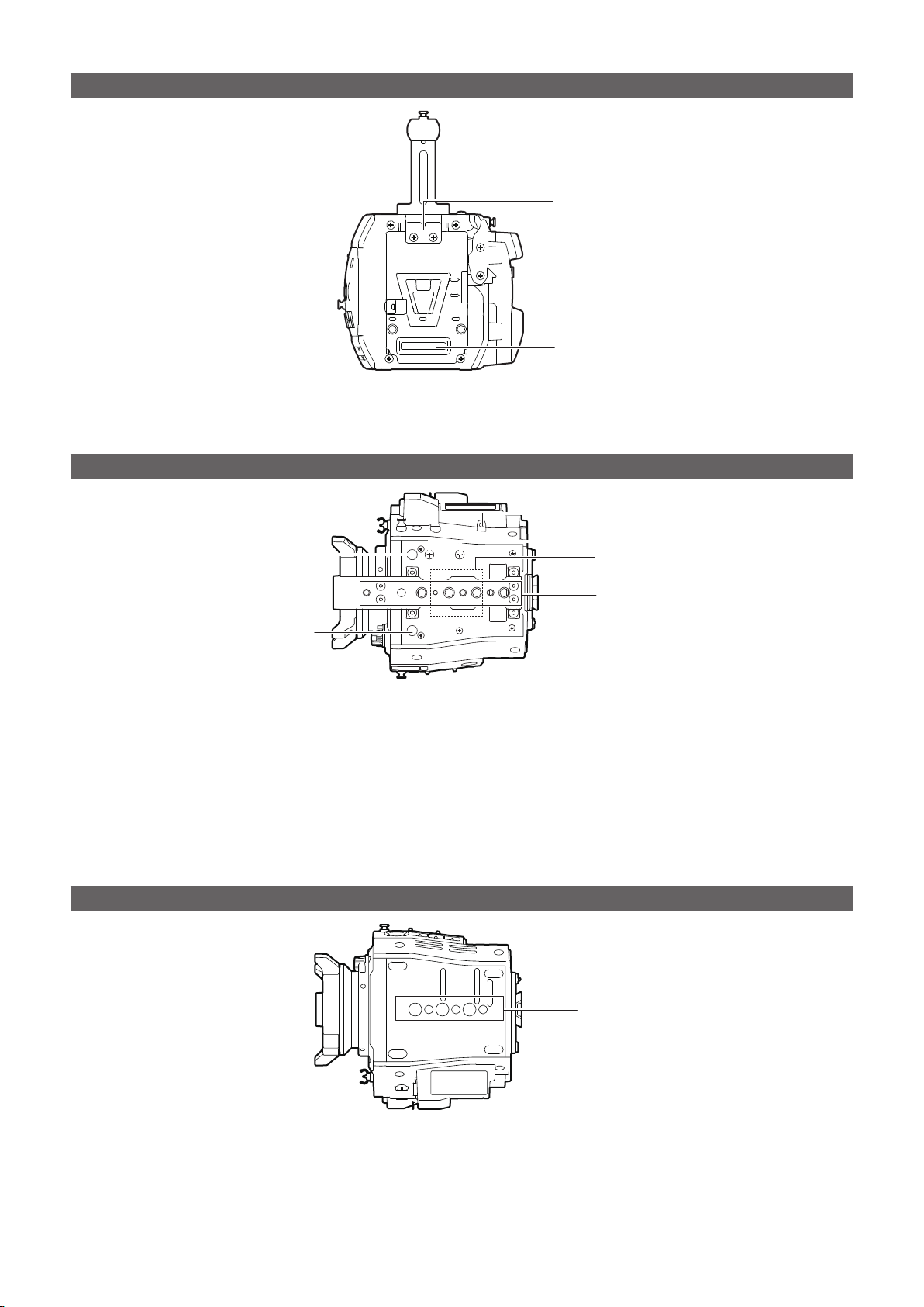
Rear
1 Lock plate
Fitting which secures the recording module in place when connected.
2 Recording module connection terminal
Terminal for connecting the recording module.
Top
1
2
1
1
1 Viewnder mounting holes
For attaching the viewnder.
2 Mounting hole for control panel mounting part
3 Microphone holder mounting position
4 GPS module position
This part has a built-in GPS module. Do not cover this part with metallic objects when the GPS is in use.
5 Accessory mounting holes
For attaching accessories.
f Mounting hole size
- 1/4-20 UNC
- 3/8-16 UNC
Bottom
2
3
4
5
1 Shoulder mount module/tripod mounting holes
For attaching the shoulder mount module or a tripod.
f Mounting hole size
- 1/4-20 UNC (screw length 5.5 mm or shorter)
- 3/8-16 UNC (screw length 5.5 mm or shorter)
1
– 13 –
Page 14
Chapter 2 Description of Parts — Recording module
Recording module
Left side
11
87 9 10
1
2
3
4
5
6
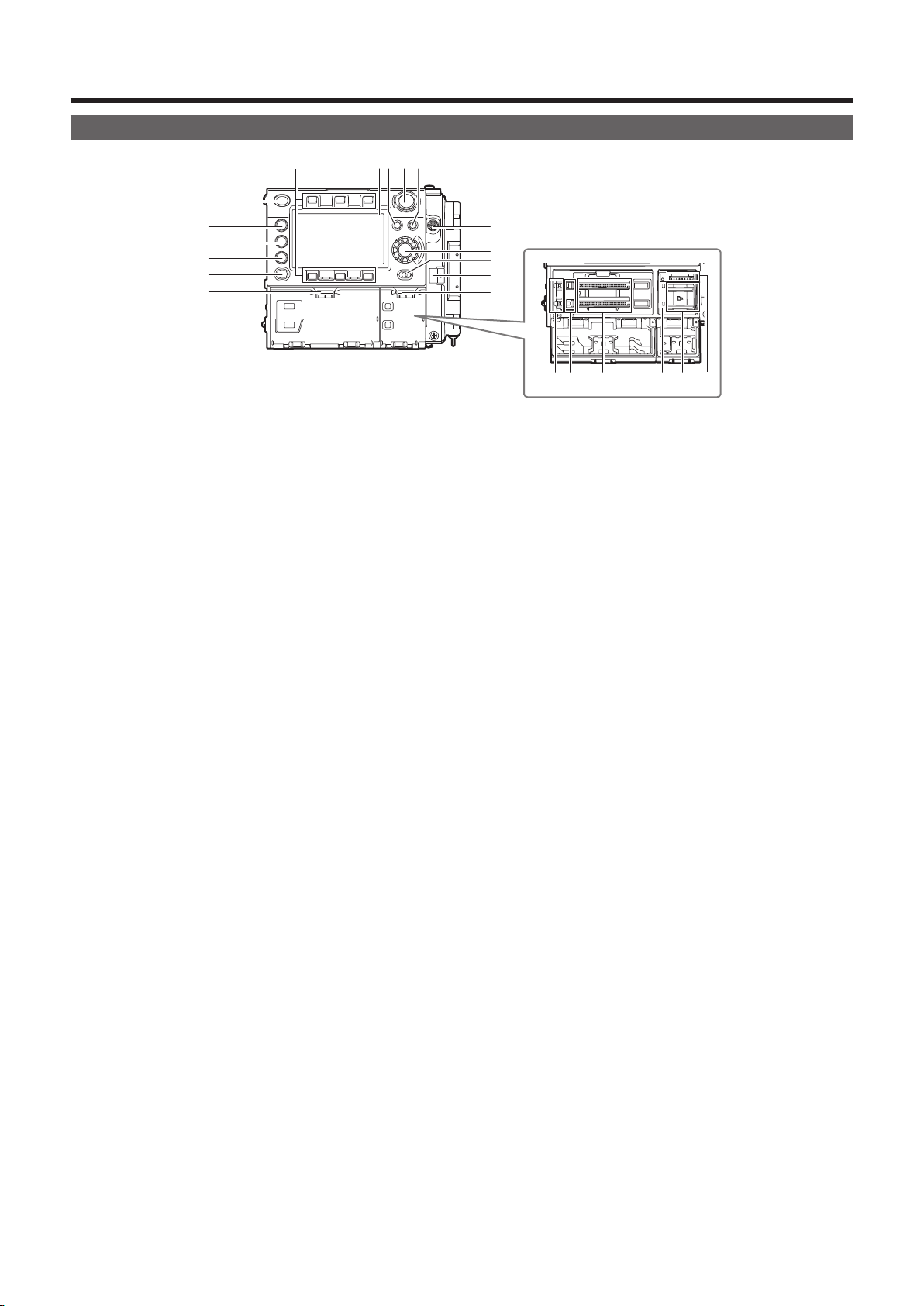
1 <HOME> button
Returns to the HOME screen when pressed.
2 <PLAY> button
Shows the PLAY screen when pressed.
3 <TC> button
Shows the TC screen when pressed.
4 <INFO> button
Shows the INFO screen when pressed.
5 <VIEW> button
Displays the camera video in the control panel.
6 Main slot open/close switch
Opens the main slot bay.
7 Control panel operation buttons
Buttons for operating the control panel. User-selected functions can be assigned to each button to function as USER buttons.
8 Control panel
Used to perform tasks such as checking the device status and setting basic items.
9 <MENU> button
Displays the setting menu in the control panel screen.
10 <REC> button
Press this button to start recording. Press this button again to stop recording. The button lights up in red during recording.
11 <EXIT> button
Restores the display to the previous state while the setting menu or control panel operation is displayed.
12 <POWER> switch
Switch on/off the power.
Even when the <POWER> switch is set to the <OFF> position, the camera is not shut off from the main power.
13 Jog dial button
Used for setting, moving items, and selecting menus on the control panel.
14 <LOCK> switch
Disables the operation of the control panel buttons and switches. (except the <REC> button)
Keep this in the <LOCK> position to prevent incorrect operation when moving the camera, etc.
15 Cable clamp
Clamp for securing the control panel extension unit cable.
16 Open/close switch for sub slot and SD memory card slot
Opens the sub slot / SD memory card slot bay.
17 Main slot lock switch 1/2
Lock switch to prevent incorrect insertion and removal in the main slot.
Recording is enabled when this is locked.
Do not release the lock during recording.
18 Main slot 1/2 access LED
Indicates the access status of recording and playback of each card inserted in main slot 1/2.
19 Main slot 1/2
Slot for expressP2 memory cards.
20 Sub slot 3/4 access LED
Indicates the access status of recording and playback of each card inserted in sub slot 3/4.
21 Sub slot 3/4
Slot for microP2 memory cards.
12
13
14
15
16
1718 19 20 21 22
– 14 –
Page 15
Chapter 2 Description of Parts — Recording module
22 SD memory card slot
Slot for SD memory cards (optional). SD memory cards are used for opening the camera setting menu, recording/opening lens les, or uploading
metadata.
Right side
1
2
3
4
5
6
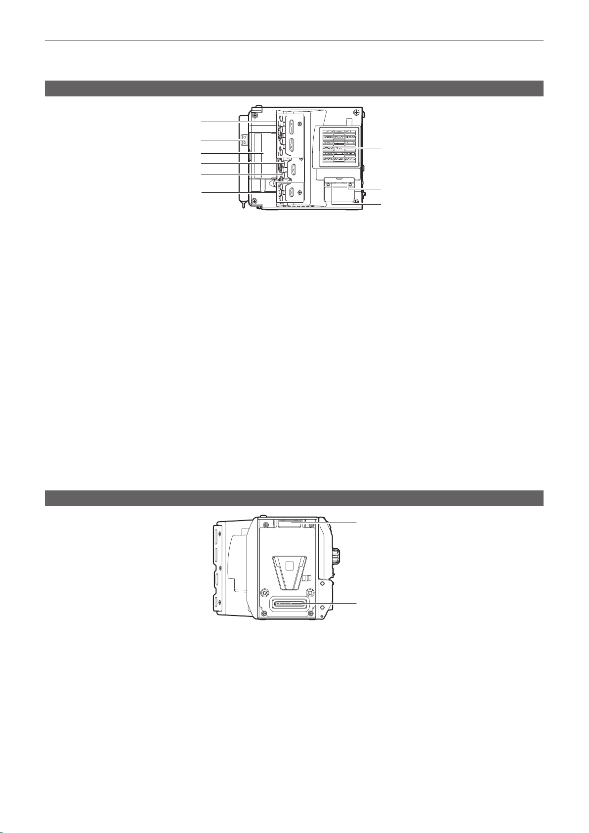
1 <SDI OUT1>/<SDI OUT2>/<SDI OUT3>/<SDI OUT4> terminal
Output terminal for 3G/HD SDI. This terminal outputs videos in SINGLE, DUAL, or QUAD mode.
For the cable to connect to this terminal, prepare a double-shielded cable equivalent to 5C-FB.
2 Light output terminal
Power supply terminal when light is connected.
3 <USB HOST> terminal (inside the cover, 5.0 V 0.5 A max)
For mounting the wireless module AJ-WM30 (optional). (Will be supported)
For the cable to connect to this terminal, prepare a double-shielded cable.
4 <TC IN/OUT> terminal
Connects to the time code input terminal of the external device when locking the time code of the external device to the time code on the camera.
For the cable to connect to this terminal, prepare a double-shielded cable equivalent to 5C-FB.
5 <GENLOCK IN> terminal
Inputs reference signals when setting the genlock on the camera unit or when externally locking the time code. The input signal is 3G/HD-SDI.
For the cable to connect to this terminal, prepare a double-shielded cable equivalent to 5C-FB.
6 <MON OUT1>/<MON OUT2> terminal
3G/HD-SDI output terminal of videos for the monitor.
For the cable to connect to this terminal, prepare a double-shielded cable equivalent to 5C-FB.
7 Fan outlet
Fan outlet for dissipating heat. Do not block this when the camera is in use.
8 <USB DEVICE> terminal
USB device terminal for connecting a USB 2.0 cable.
For the cable to connect to this terminal, prepare a double-shielded cable.
9 <LAN> terminal
For connecting a LAN (100BASE-TX) cable. (Will be supported)
For the cable to connect to this terminal, prepare a shielded cable.
7
8
9
Front
1 Lock angle
Fitting which secures the camera unit (optional) in place when connected.
2 Camera unit connection terminal
Terminal for connecting the camera unit (optional).
1
2
– 15 –
Page 16
Chapter 2 Description of Parts — Recording module
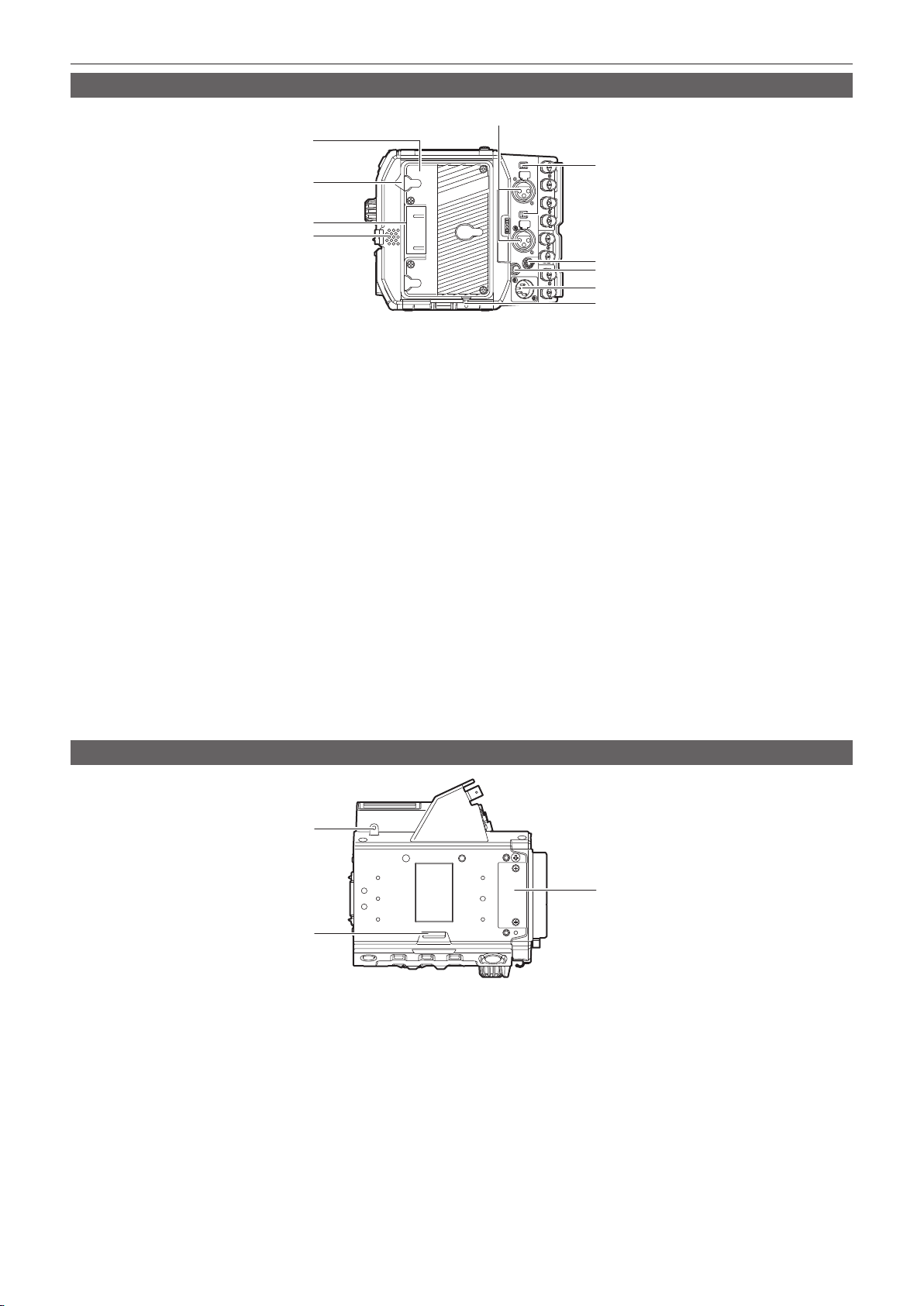
Rear
5
1
6
2
3
4
7
8
9
10
1 Battery holder
For mounting Anton/Bauer batteries.
2 Battery release lever
Pull this battery release lever down to release the battery.
3 Battery contact terminals
Contact terminals for the battery.
4 Speaker
EE audio can be monitored during recording while playback audio can be monitored during playback.
The alarm is output in sync with ashing/lighting of the warning indicator.
Audio from the speaker automatically is turned off when headphones are connected to the <PHONES> terminal.
5 <AUDIO IN 1>/<AUDIO IN 2> terminal
Connect the audio equipment or the microphone.
6 <LINE>/<MIC> switch
Switch for switching audio input signals connected to the <AUDIO IN 1>/<AUDIO IN 2> terminal.
<LINE>: Select when audio equipment is connected by the line input.
<MIC>: Select when a microphone is connected.
7 <PHONES> terminal
Connecting terminal of headphones for audio monitor. (Stereo mini jack)
8 <DC OUT/RS> terminal
Terminal for DC 12 V output and REC trigger input. The DC output provides a maximum current of 1.0 A.
9 <DC IN> terminal
Input terminal for connecting an external DC power supply.
10 <LIGHT CONTROL> switch
Control switch when light is connected to the light output terminal.
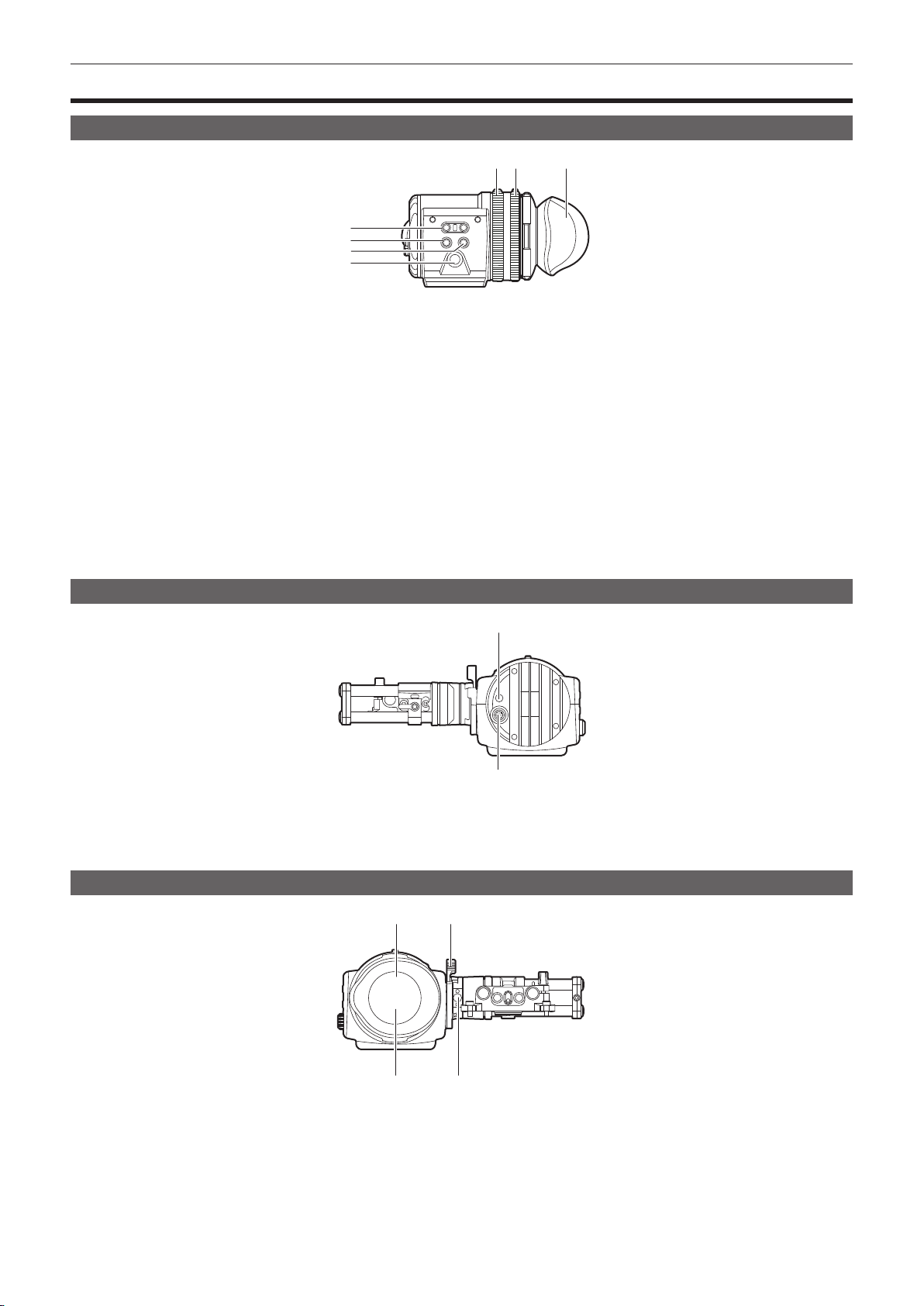
Top side
1
2
1 Mounting hole for control panel mounting part
2 <RELEASE> switch
Switch for removing the control panel.
3 External unit connection terminal
Terminal for future expansions. Keep the cover on during normal use.
3
– 16 –
Page 17

Chapter 2 Description of Parts — Recording module
Bottom
1 Shoulder mount module/tripod mounting holes
For attaching the shoulder mount module or a tripod.
f Mounting hole size
- 1/4-20 UNC (screw length 5.5 mm or shorter)
- 3/8-16 UNC (screw length 5.5 mm or shorter)
1
– 17 –
Page 18
Chapter 2 Description of Parts — Electronic HD color viewnder
Electronic HD color viewnder
Left side
5 6
1
2
3
4
1 <EVF USER 1>/<EVF USER 2> buttons
User-selected functions can be assigned to each button. Pressing a button performs the assigned function. Functions are set on the viewnder
menu.
2 <CAM MENU> button
Displays the camera menu screen.
3 <EVF MENU> button
Displays the viewnder menu screen.
4 Jog dial
Operation dial.
Used for setting, moving, and selecting in menus.
5 Zoom ring
Ring which enlarges/reduces the size of the viewnder display screen.
This is used to enlarge the display when adjusting the focus. When the display is enlarged, some parts of the video may be hidden.
6 Visibility adjustment ring
Ring which adjusts the visibility. Turn this ring while pressing and holding the upper button.
7 Eye cup
7
Front
1
2
1 Tally LED
Lights up in red during recording. This can be disabled in the viewnder menu.
2 Connection terminal
Terminal for connecting the supplied cable. This connects to the camera module (optional).
Rear
1 2
3 4
1 Eye sensor
Screen is displayed on the viewnder when an eye is brought close.
The eye sensor may not work properly depending on the shape of glasses in use, how you hold the camera, or the strong light hitting around the eye
piece.
2 Lock lever
Secures the viewnder in place.
3 Eye piece lter
Protective lter against dust, water, and moisture. Use the camera with this attached.
– 18 –
Page 19

Chapter 2 Description of Parts — Electronic HD color viewnder
4 Stopper
Used when removing the viewnder from the slider unit.
Top
1 Lock lever (left/right position)
Adjusts the position of the viewnder (left/right).
2 Lock lever (front/back position)
Adjusts the position of the viewnder (front/back).
2
1
– 19 –
Page 20
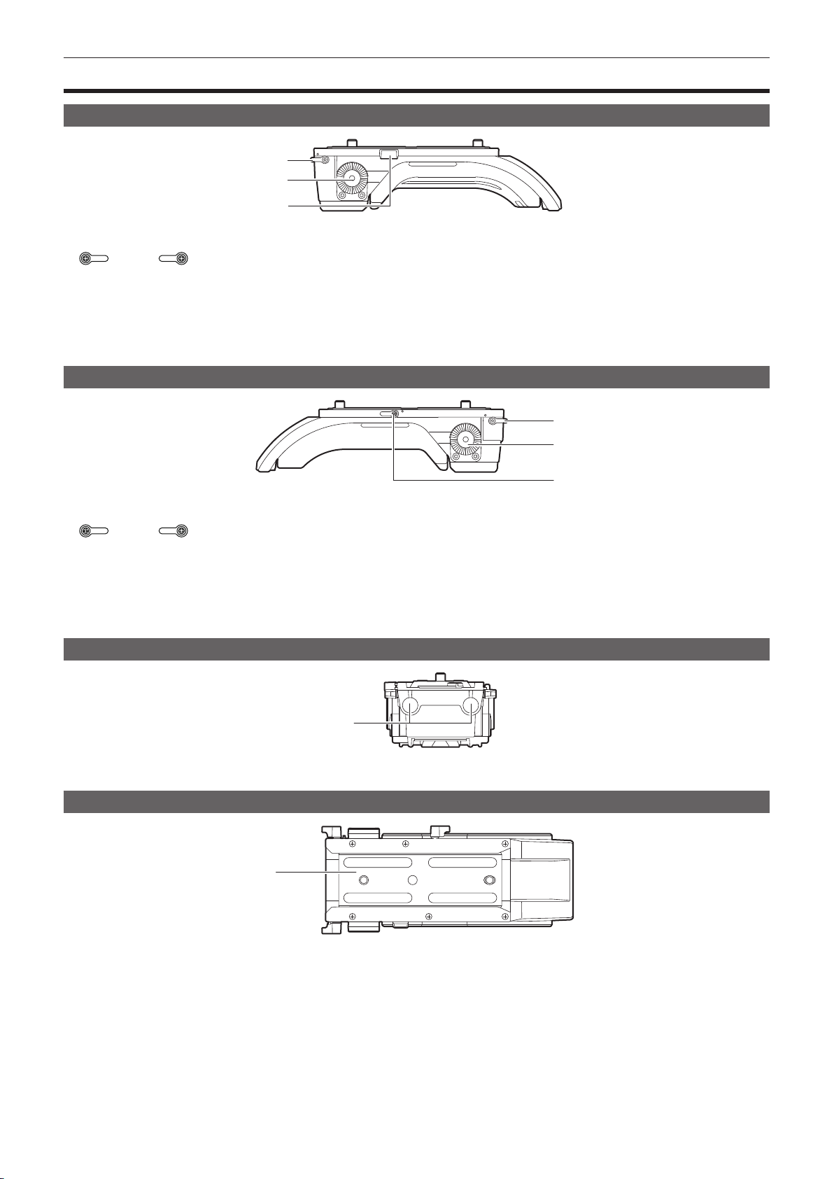
Chapter 2 Description of Parts — Shoulder mount module
Shoulder mount module
Left side
1
2
3
1 Support rod lock knob
Secures the rod in place.
: Release, : Lock
2 Accessory attachment (rosette)
Attach accessories such as hand grip.
f Mounting screw size
- M6 (screw length 9 mm or shorter)
3 Stopper
Pressed when removing the slide rail from the shoulder mount module.
Right side
1
2
1 Support rod lock knob
Secures the rod in place.
: Release, : Lock
2 Accessory attachment (rosette)
Attach accessories such as hand grip.
f Mounting screw size
- M6 (screw length 9 mm or shorter)
3 Slide rail lock knob
Secures the slide rail in place.
Front
1 Support rod mounting holes
Holes for connecting a rod with a diameter of 15 mm.
Top
1
3
1
1 Slide rail
Attaches to the camera.
– 20 –
Page 21

Chapter 3 Preparation
Before you use the camera, assemble the unit following the procedures in this chapter. The mounting of accessories is also described in this chapter.
Page 22
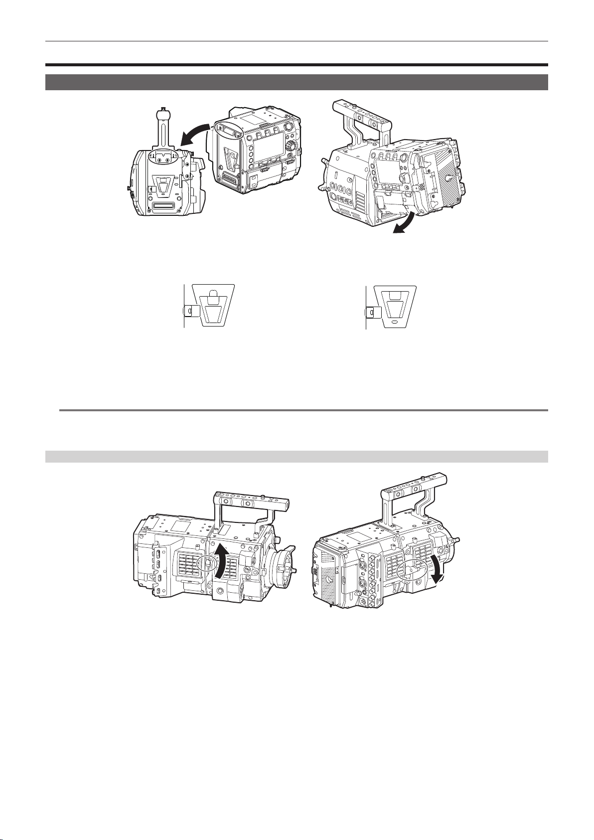
Chapter 3 Preparation — Assembling modules
Assembling modules
Assembling the camera module and recording module
Fig. 1 Fig. 2
Fig. 3 Fig. 4
Align the upper lock angle in front of the recording module with the upper lock plate at the rear of the camera module. (Fig. 1)
1
Firmly push in the recording module and connect the connection terminals of the camera module and recording module. (Fig. 2)
2
NOTE
@@
t The modules cannot be joined together if the V edge of the camera module is down. (Fig. 3) Push down the recording module release lever of the
camera module to raise the V edge. (Fig. 4)
t Do not touch the mechanical parts near the V edge. The V edge will move quickly, which may cause injury.
Disassembling
Fig. 1
Fig. 2
Push down the recording module release lever (Fig. 2) while pulling up the lock knob (red) of the recording module release lever
1
(Fig. 1).
The rear part of the recording module will slightly come up.
It will be difcult for the rear part to come up when heavy items such as batteries are mounted.
Lift the recording module.
2
Do not hold the control panel part. Doing so may cause the control panel to detach and fall.
Remove the upper lock angle in front of the recording module from the upper lock plate at the rear of the camera module.
3
– 22 –
Page 23
Chapter 3 Preparation — Assembling modules
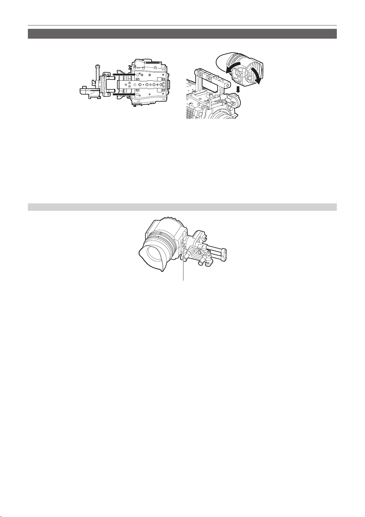
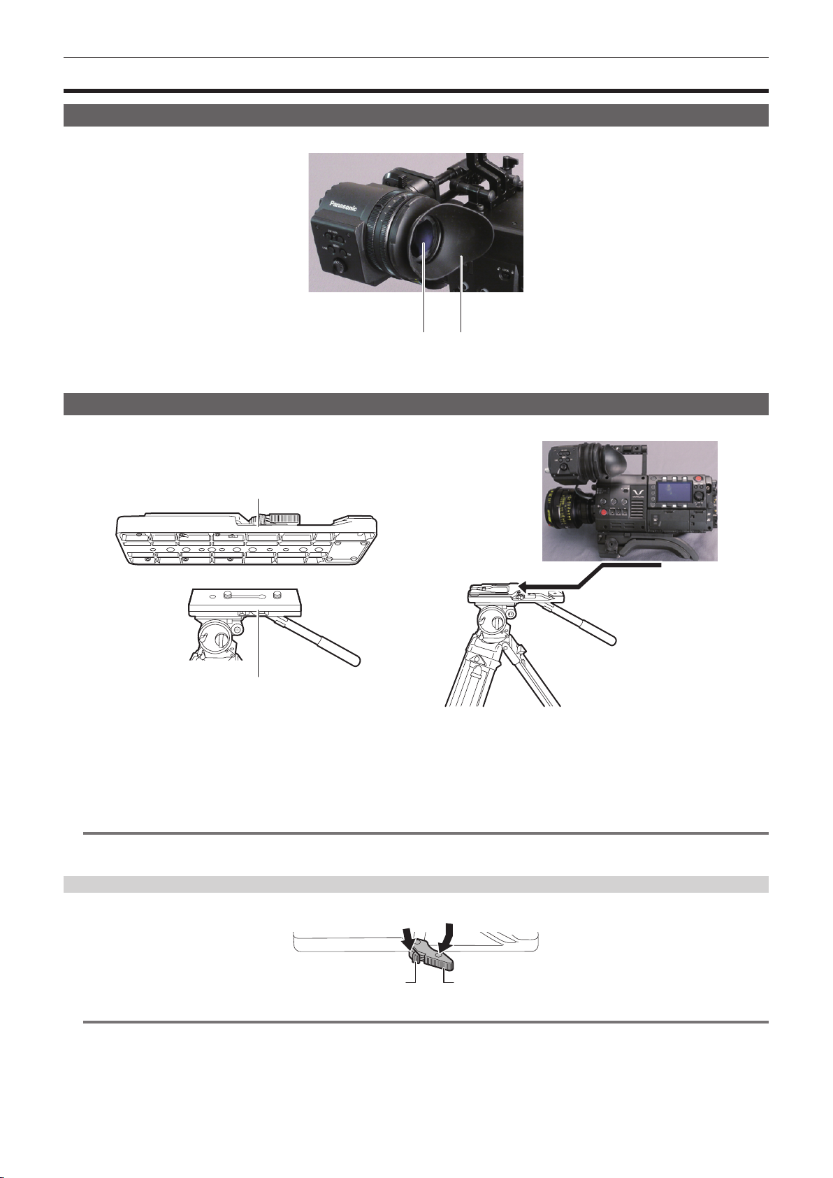
Mounting the Electronic HD color viewnder
Lock
Release
Fig. 1
Attach the slider unit to the viewfinder mounting holes on top of the camera module using the two supplied screws. (Fig. 1)
1
Slide the viewfinder plate from above into the slider unit. (Fig. 2)
2
Release the viewnder lock lever by pushing it forward.
Push down the lock lever backwards to lock.
3
Connect the supplied connecting cable to the viewfinder connection terminal and the camera module’s <VF> terminal.
4
Connect by aligning the red mark on the connector.
Disassembling
a
a: Stopper
Remove the connecting cable.
1
Fig. 2
Push down the lock lever towards the front to release the lock.
2
Lift the viewfinder while pulling the stopper.
3
Remove the slider unit clamping screw.
4
– 23 –
Page 24
Chapter 3 Preparation — Assembling modules
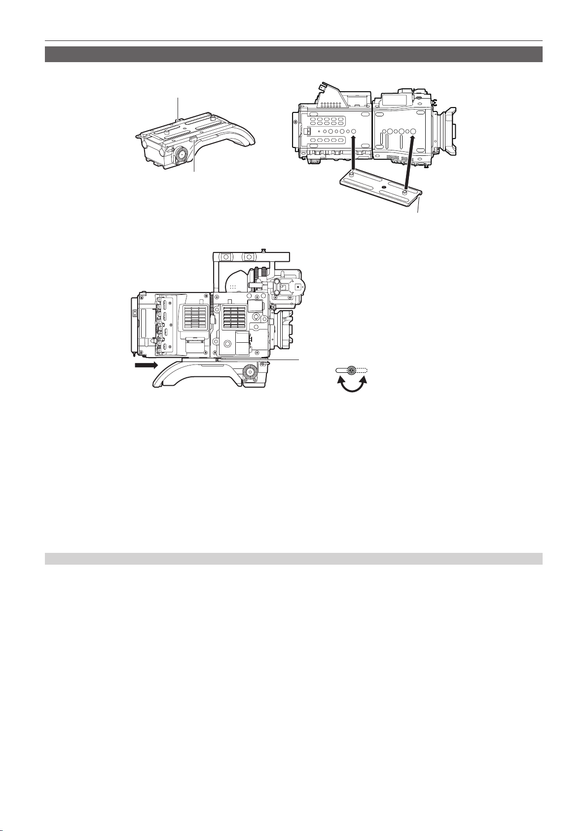
Mounting the shoulder mount module
Mount the shoulder mount module after mounting the camera module and recording module.
Slide rail lock knob
Stopper
Fig. 1 Fig. 2
Stopper opening
Slide rail lock knob
Lock Release
Fig. 3
Release the slide rail lock knob.
1
Remove the slide rail from the shoulder mount module while pressing the stopper. (Fig. 1)
2
Orient the stopper opening of the slide rail toward the front of the camera, and securely mount to the bottom of the camera with
3
the supplied two screws on the screw holes indicated in the figure. (Fig. 2)
Slide the camera forward along the groove in the shoulder mount module from the rear until it clicks. (Fig. 3)
4
Before mounting, conrm that the slide rail lock knob is released.
After adjusting the slide position of the camera considering its weight balance, lock by turning the slide rail lock knob clockwise.
5
Conrm that the camera is securely locked. The camera may fall causing a malfunction or injury when the camera is off balance or the screws are
not locked securely.
Disassembling
Release the slide rail lock knob.
1
Remove the camera from the shoulder mount module by sliding it toward rear while pressing the stopper.
2
Loosen the two screws and remove the slide rail from the bottom of the camera.
3
If the shoulder mount is mounted on a tripod, lock the pan lock lever and the tilt lock lever of the tripod. It may lose balance and fall, causing a
malfunction or injury.
– 24 –
Page 25
Chapter 3 Preparation — Attaching and removing accessories
Attaching and removing accessories
Eye cup/eye piece lter
The eye cup and eye piece lter can be removed. Always use the camera with these attached.
b a
a: Eye cup
b: Eye piece lter
Attaching a tripod
When mounting the camera on a tripod, use the optional tripod adaptor (SHAN-TM700).
Tripod adaptor
Pan head
Fig. 1 Fig. 2
Mount the tripod adaptor on the tripod. (Fig. 1)
1
Mount the camera on the tripod adaptor. (Fig. 2)
2
Slide the camera forward along the grooves until you hear a click.
NOTE
@@
t Select an appropriate hole in the adaptor, taking into account the center of gravity of the camera and tripod adaptor combined.
Also, make sure that the diameter of the selected hole matches the diameter of the pan head screw.
Removing the camera from the tripod adaptor
While holding the red lever down, move the black lever in the direction of the arrow, and slide the camera backward to remove it.
Red lever Black lever
NOTE
@@
t If the tripod adaptor pin does not return to its original position after the camera has been removed, hold the red lever down and move the black lever in
the direction of the arrow again, in order to return the pin to its original position.
The camera cannot be mounted if the pin remains in the center. Be careful.
– 25 –
Page 26

Chapter 3 Preparation — Attaching and removing accessories
Attaching the rain cover
The gure below shows an example of use of the rain cover SHAN-RC700 (optional).
Tighten the cord
Secure with the surface
fastener
– 26 –
Page 27

Chapter 3 Preparation — Power supply
Power supply
A battery or an external DC power supply can be used as the power supply.
Using batteries
Connection of the following batteries to the camera has been veried.
r Anton/Bauer batteries
HYTRON140
DIONIC HC/DIONIC HCX/DIONIC HD
r IDX batteries
ENDURA HL9
NOTE
@@
t Other batteries can be supported by changing [BATTERY SELECT] in [MENU] → [SYSTEM SETTINGS] → [BATTERY]. Use of batteries that are
already veried as connectable to the camera is recommended.
t Before you use a battery, charge it with a battery charger. (For details on charging, refer to each operating instructions.)
Mounting and setting battery
Using Anton/Bauer batteries
Release lever
Anton/Bauer batteries
Mount the Anton/Bauer battery.
1
Insert the battery terminal and slide in the direction of the arrow.
2
Set the battery type.
3
From [MENU] → [SYSTEM SETTINGS] → [BATTERY] → [BATTERY SELECT], select the battery type.
For details, refer to “Setting menu basic operations” (page 83).
NOTE
@@
t To remove the battery, keep the release lever of the battery holder completely down, slide the battery in the opposite direction when you mounted it.
Using V-mount type batteries
Mount the V-mount type battery plate. As shown in the illustration, insert and slide in the direction of the arrow.
Release lever
Mount the V-mount type battery plate.
1
Slide in the direction of the arrow.
2
Set the battery type.
3
f From [MENU] → [SYSTEM SETTINGS] → [BATTERY] → [BATTERY SELECT], select the battery type.
– 27 –
Page 28
Chapter 3 Preparation — Power supply
NOTE
@@
t Contact your dealer for information about the V-mount type battery plate.
t When the V-mount type battery plate is used, % (percent) is not displayed even if batteries with a battery level indicator function are used.
t When removing the plate, remove by sliding the release lever.
t When using a battery that is not included in [BATTERY SELECT], set [other], then set [FULL Volt], [NEAR END Volt], or [END Volt] according to the
characteristics of the battery.
Using external DC power supply
External DC power supply
<DC IN> terminal
DC cable
Connect the external DC power supply to the <DC IN> terminal of the camera.
1
Turn on the power switch of the external DC power supply (if the external DC power supply has a power switch).
2
Turn the <POWER> switch of the camera to <ON>.
3
r External DC power supply
Connect after making sure that the output voltage of the external DC power supply is compatible with the rated voltage of the camera.
Select an output amperage for the external DC power supply with a margin above the total amperage of the connected devices.
The total amperage of connected devices can be calculated with the following formula.
Total power consumption ÷ Voltage
When the power of the camera is turned on, inrush current is generated. Insufcient power supply when turning on the power may cause a malfunction. We
recommend that you use an external DC power supply that can assure double the capacity of the total power consumption of the camera and connected devices
that are turned on by interlock when the power of the camera is turned on (such as lenses). For the DC cable, use a dual-core shielded wire of AWG16 (nominal
cross section area 1.309 mm
f Make sure of the pin alignment of the DC output terminal of the external DC power supply and the camera <DC IN> terminal, and connect the polarity
correctly.
If the +12 V power supply is mistakenly connected to the GND terminal, it may cause re or malfunction.
2
) or thicker.
DC IN
1 GND
2 NC
3 NC
4
Panasonic Parts No.: K1AA104H0038
Manufacturer Parts No.: HA16RX-4P (SW1) (76) (Hirose Electric Co.)
+12 V
NOTE
@@
t When both the battery and the external DC power supply are connected, the power supply from the external DC power supply has priority. The battery
may be removed while using the external DC power supply.
t When using an external DC power supply, always turn the power switch of the external DC power supply on before turning the <POWER> switch of
the camera <ON>. If the operations are performed in reverse, the camera may malfunction because the external DC power supply output voltage rises
too slowly.
t When switching the power supply from an external DC power supply to the battery, carefully remove the DC cable from the <DC IN> terminal.
Removing the cable quickly may temporarily stop the camera’s operation.
t When power is supplied from the <DC IN> terminal, the light circuit does not function. The light circuit can be used only when power is supplied from
the Anton/Bauer battery plate.
t When a battery is connected to the <DC IN> terminal, set [MENU] → [SYSTEM SETTINGS] → [BATTERY] → [EXT DC IN SELECT] to [BATTERY],
then set [FULL Volt], [NEAR END Volt], or [END Volt] according to the characteristics of the battery. However, in this the case, the percent (%) display
will not be available for batteries with a battery level indicator function.
– 28 –
Page 29
Chapter 3 Preparation — Mounting and adjusting the lens
Mounting and adjusting the lens
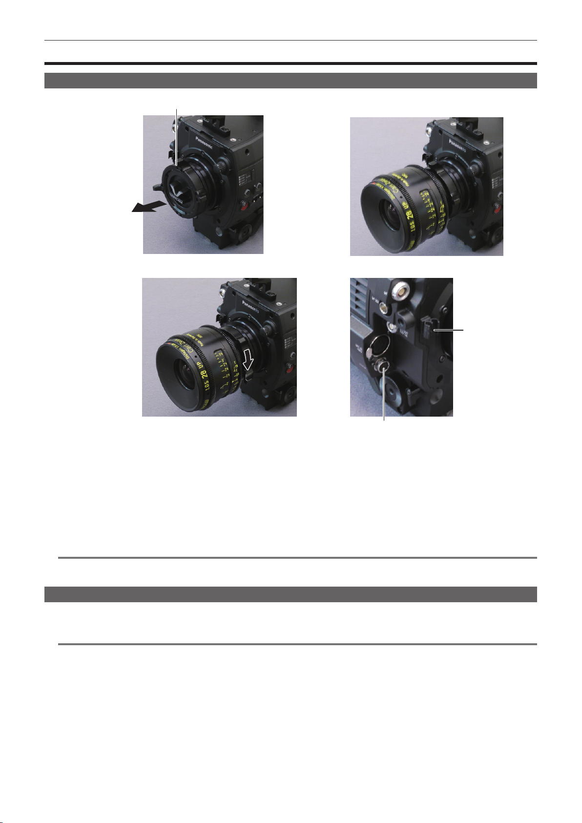
Mounting the lens
Lens lever
Mount cap
Fig. 1 Fig. 2
Cable clamp
<LENS> terminal
Fig. 3
Raise the lens lever and remove the mount cap. (Fig. 1)
1
Align the convex portion at the upper right of the lens mount with the concave portion at the lens mount to mount the lens. (Fig.
2
2)
Lower the lens lever to firmly clamp the lens. (Fig. 3)
3
If a cable is attached to the lens, secure the cable through the cable clamp and connect it to the <LENS> terminal. (Fig. 4)
4
NOTE
@@
t For handling the lens, refer to the lens operating instructions.
t When the lens is removed, install the mount cap to protect the device.
Fig. 4
Flange lens back adjustment
The camera is equipped with the adjustment function of the ange back (distance from the lens mounting surface to the image formation surface). As
the factory setting, it is adjusted with high accuracy. If you adjust the ange back, perform the adjustment in an well-equipped environment.
NOTE
@@
t Contact your dealer for information about the adjustment method.
– 29 –
Page 30
Chapter 3 Preparation — Connecting to the DC output terminal
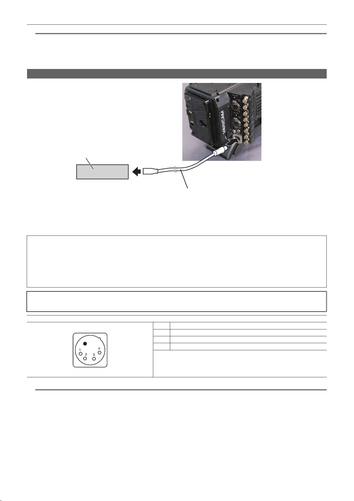
Connecting to the DC output terminal
Connecting the <DC OUT/RS> terminal to the external recording start/stop switch
It is possible to get a 1.0 A current from the <DC OUT/RS> terminal of the recording module.
Recording start/stop can be controlled by connecting an external switch to this terminal.
An LED connected to this terminal can also be used as a tally lamp. This is useful for shooting video when xing the camera on a crane.
(Connection example)
Cable connector
HR10A-7R-4SC (73)
1
4
LED
Resistance
<DC OUT/RS> terminal
Hirose Electric Co.
23
Recording
start/stop
1 GND
2 TALLY OUT
Open collector output on the camera side
Tally lamp on Low impedance
Tally lamp off High impedance
3 Recording start/stop switch
This is connected in parallel to the <REC> button on the camera or the VTR button on the lens.
4 +12 V
NOTE
@@
t Make sure that polarity is correct before connecting an external device. Otherwise, it may result in a malfunction.
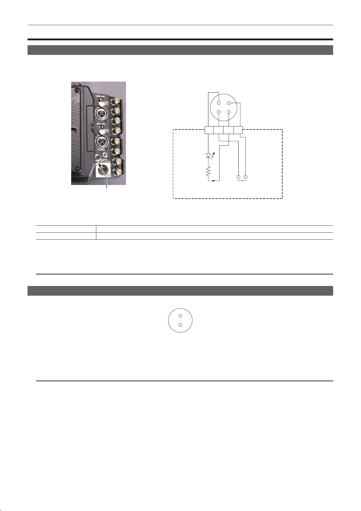
Connecting to the <DC OUT> terminal
It is possible to get a 1.0 A current from the <DC OUT> terminal of the camera module.
1
2
Cable connector
0B.302
LEMO
1 GND
2 +12 V
NOTE
@@
t Make sure that polarity is correct before connecting an external device. Otherwise, it may result in a malfunction.
– 30 –
Page 31

Chapter 3 Preparation — Setting the date/time of the internal clock
Setting the date/time of the internal clock
The value of the time is recorded to content (clips) and affects the thumbnail playback order. Before recording, be sure to check and set the date and
time zone.
Press the <MENU> button.
1
f The [MENU] screen is displayed on the control panel.
Select [MENU] → [SYSTEM SETTINGS] → [CLOCK] → [CLOCK SETTING] to set the year, month, day, and time.
2
The year setting upper limit is 2037. For details on the settings menu, refer to “Setting menu basic operations” (page 83).
Select [MENU] → [SYSTEM SETTINGS] → [CLOCK] → [TIME ZONE] to set the time difference from Greenwich Mean Time.
3
The time zones are always recorded as metadata together with date/time.
NOTE
@@
t You can correct the date and time of the internal clock from GPS by enabling the GPS function.
r Time zone table
Time difference Region Time difference Region
00:00 Greenwich
−00:30 +01:30
Azores
−01:00
−01:30 +02:30
Mid-Atlantic
−02:00
−02:30 +03:30
Buenos Aires
−03:00
Newfoundland
−03:30
Halifax
−04:00
−04:30 +05:30
New York
−05:00
−05:30 +06:30
Chicago
−06:00
−06:30 +07:30
Denver
−07:00
−07:30 +08:30
Los Angeles
−08:00
−08:30 +09:30
Alaska
−09:00
Marquesas Islands
−09:30
Hawaii
−10:00
−10:30 +11:30
Midway Islands
−11:00
−11:30 +12:45
Kwajalein Atoll
−12:00
+00:30
+01:00
+02:00
+03:00
+04:00
+04:30
+05:00
+06:00
+07:00
+08:00
+09:00
+10:00
+10:30
+11:00
+12:00
+13:00
Central Europe
Eastern Europe
Moscow
Tehran
Abu Dhabi
Kabul
Islamabad
Bombay
Dakar
Yangon
Bangkok
Beijing
Tokyo
Darwin
Guam
Lord Howe Island
Solomon Islands
Norfolk Island
New Zealand
Chatham Islands
NOTE
@@
t Be sure to make this setting before using the camera for the rst time. After, do not change the setting during use.
t Clock accuracy is a lunar inequality of approximately ±30 seconds with the power off. When accurate time is required, check and reset the time when
the power is turned on.
Note that if the time is received using the built-in GPS, the time of the internal clock (local date and time) is maintained accurately based on the time
received (Greenwich mean time) and the time zone.
If the time display of the internal clock is different from the local time, the time zone setting may be incorrect. Check the time zone setting again
(internal clock does not need to be set again).
t The internal clock runs for several years on the built-in lithium cell of the camera. When the lithium cell runs out of power, [BACKUP BATT EMPTY] will
be displayed in the viewnder when the camera is turned on. For details, refer to “Maintenance” (page 107).
– 31 –
Page 32

Chapter 4 Video Recording and Color
Grading
This chapter describes the video combinations that can be recorded and the color grading (in-camera color grading) that can be performed using the
camera.
Page 33

Dual-recording
The camera has two built-in recorders.
r Main recorder
Chapter 4 Video Recording and Color Grading — Dual-recording
Sub slot
Main slot
Card slot
Compatible memory cards expressP2 memory card
f P2 memory cards cannot be used when the 4K format or the variable frame rate function is enabled.
f P2 memory cards of 2 GB cannot be used.
f R, A, and E series P2 memory cards cannot be used for 1080/59.94P and 1080/50P.
expressP2 memory card slot × 2
P2 memory card (with some restrictions)
r Sub recorder
Card slot
Compatible memory cards microP2 memory card
f Proxy data can be recorded simultaneously in the sub recorder (with some restrictions)
f Videos with a variable frame rate cannot be recorded using the sub recorder.
f Recording using only the sub recorder is not possible.
microP2 memory card slot × 2
– 33 –
Page 34

Chapter 4 Video Recording and Color Grading — Selecting the resolution, codec, and video format for recording
Selecting the resolution, codec, and video format for recording
You can select the recording resolution, recording codec, and recording frame rate.
f [PIXEL]: Resolution
f [MAIN CODEC]: Recording format
f [FREQUENCY]: System frequency
f VFR: Variable frame rate function (maximum frame rate)
f [SUB CODEC]: Sub recording format
f [PROXY]: Proxy data recording (Proxy data recording does not function when the variable frame rate function is enabled.)
[PIXEL] [MAIN CODEC] [FREQUENCY] VFR
[4096×2160]
[3840×2160]
[1920×1080]
Recording format
f OP-1b format: [AVC-Intra4K 422]/[AVC-Intra2K 422]/[AVC-LongG50]/[AVC-LongG25]
f OP-Atom format: [AVC-Intra100]
NOTE
@@
t Operation mode of the image sensor and signal processing will change depending on selection of [MAIN CODEC].
[AVC-Intra4K 422] [23.98p] 60fps [AVC-Intra2K 422]
[25.00p] 50fps
[29.97p] 60fps
[50.00p] 50fps [AVC-Intra2K 422] —
[59.94p] 60fps
[AVC-Intra4K 422] [23.98p] 60fps [AVC-Intra100]
[25.00p] 50fps
[29.97p] 60fps
[50.00p] 50fps [AVC-Intra100]
[59.94p] 60fps
[AVC-Intra100] [23.98p] 60fps [AVC-Intra100]
[25.00p] 50fps
[29.97p] 60fps
[50.00p] 50fps [AVC-Intra100]
[59.94p] 60fps
(maximum frame rate)
[SUB CODEC] [PROXY]
[AVC-LongG50]
[AVC-LongG25]
[AVC-LongG25]
[AVC-LongG50]
[AVC-LongG25]
[AVC-LongG25]
[G3.5(1024×540)]
[G3.5(960×540)]
—
[G3.5(960×540)]
—
– 34 –
Page 35

Chapter 4 Video Recording and Color Grading — In-camera grading
In-camera grading
This chapter describes the camera’s grading function. You can record V-Log (master video) in the main recorder and grading video in the sub recorder
simultaneously.
Grading function
[CDL]:
f Controlled using [Slope], [Offset], [Power] (RGB stand-alone), and [Saturation] (RGB common).
f Can be controlled in real-time using the camera’s control panel.
f Control parameters are saved to a le and stored in a P2 card together with videos, etc.
f The le extension is .cdl.
[3D LUT]:
f Controlled in a 17-grid [3D LUT] le.
f Uploads data within the camera through an SD memory card.
f Control parameters are saved to a le and stored in a P2 card together with videos, etc.
f The le extension is .vlt.
Control combinations through settings
Output Picture Adjustment
[MAIN COLOR] [Grading SEL] [SUB COLOR] [3D LUT] [CDL]
[V-Log]
[ON]
[V-Log]
[OFF]
[V-709] [OFF] [V-709] [OFF] [OFF] V-709 V-709
[3D LUT] [OFF] [3D LUT] [OFF] [OFF] 3D LUT 3D LUT
When [MAIN COLOR] is set to [V-Log] or [3D LUT], the setting in [MENU] → [CAMERA SETTINGS] → [Enhanced] → [Enhanced SW] is xed to [OFF].
[Grading]
[V-Log]
[V-709]
[OFF]/[V-709]/
[Loaded File]
[OFF] [OFF]
[ON]/[OFF]
[MON 1]
[MON 2]
V-Log
Grading
V-Log
V-709
[EVF]
V-Log
Grading
V-709
LCC
V-Log
V-709
LCC
– 35 –
Page 36

Chapter 4 Video Recording and Color Grading — P2 card
P2 card
Inserting a P2 card
When using the camera for the rst time, be sure to set the time data beforehand. (page 31)
Insert the expressP2 memory card into the main slot and the microP2 memory card into the sub slot.
Main slot 1
Eject button
Sub slot 3
Sub slot card access LED
Card slot cover
Main slot 2
Main slot lock switch
Fig. 1 Fig. 2 Fig. 3
Open the card slot cover. (Fig. 1)
1
Insert a card into the card slot. (Fig. 2)
2
f expressP2 memory cards (main slot)
- Slide the main slot lock switch to the left to release the lock.
- Insert the card with the logo facing up until the eject button pops out.
- Press the eject button that pops up to the right.
- Slide the main slot lock switch to the right to lock.
f microP2 memory cards (sub slot)
- Insert with the label facing up.
Make sure that the card access LED is lit in orange or green. (Fig. 3) (page 37)
3
When two P2 cards are inserted in the card slots, the P2 card with the smaller slot number will be recorded to rst. Note, however, that regardless of
the slot number, if a P2 card is inserted later, that P2 card will not be accessed until the previously inserted P2 card has been recorded to.
f Example: When expressP2 memory cards are inserted in two slots
If expressP2 memory cards are inserted into the two slots, the cards are used as expressP2 memory cards in the order of the slot number 1 → 2.
However, if you remove the expressP2 memory card from slot 1 and then insert it again, recording to the expressP2 memory cards will take place
in the order slot 2 → 1.
The P2 memory card number to be recorded to is maintained even if the camera is turned off. When the camera is next turned on, recording can be
continued to the same P2 memory card as before the camera was turned off.
Close the cover of the main slot or sub slot.
4
Sub slot 4
Main slot card access LED
NOTE
@@
t The topmost slot on the sub slot side is for the SD memory card used for conguration, etc. Videos and other forms of data cannot be recorded.
t Be sure to close the card slot cover in order to prevent dropping, dust, and static electricity.
t Be sure to format P2 cards only on the camera.
t Operation is not guaranteed if SDHC/SDXC memory cards other than microP2 memory cards are used in the sub slot.
t If a microP2 memory card is inserted slowly, [FORMAT ERROR!] or [NOT SUPPORTED!] may be displayed. In such a case, insert the card again.
– 36 –
Page 37

Chapter 4 Video Recording and Color Grading — P2 card
Removing a P2 card
Fig. 1 Fig. 2
Open the card slot cover.
1
Remove the card.
2
f expressP2 memory cards
- Slide the main slot lock switch to the left to release the lock.
- Lift the eject button (Fig. 1), and press in. (Fig. 2)
f microP2 memory cards
- Press in the microP2 card further into the camera and let go.
- The microP2 memory card is released from the card slot, and the microP2 memory card can be removed.
NOTE
@@
t Do not remove the P2 card after inserting it, while it is being accessed, or being detected (card access LED ashing in orange). Otherwise, it may
result in a malfunction.
t If the P2 card is removed while being accessed, [TURN POWER OFF] is displayed on the viewnder screen, and the camera gives out a warning
indication by a warning lamp, etc. Also, all card access LEDs ash rapidly in orange. Turn off the power. (page 108)
t If the P2 card is removed while being accessed, clips on it may become irregular. Check the clips and restore them, if required.
t If the P2 card being formatted is removed, formatting of the P2 card is not guaranteed. In this case, [TURN POWER OFF] is displayed on the
viewnder screen displays. Turn off the power and then back on again, and reformat the P2 card.
t If a P2 card is inserted into another slot during playback, the inserted card is not recognized and the card access LED does not light up. The P2 card
will start to be recognized when playback ends.
t Even if a P2 card is inserted in a vacant card slot during recording, the P2 card may not be recognized immediately in the following instance:
- Immediately after a recording slot is switched
Preventing accidental erasure
In order to prevent erasing the recorded contents of the P2 card by mistake, turn the write protect switch on the P2 card to the Protect side (or the LOCK
side).
Write-protect switch Write-protect switch
NOTE
@@
t Write-protect switch can be switched while the card is being accessed (during recording or playback), but does not take effect until accessing of the
card stops.
Card access LEDs and P2 card status
Card access LED P2 card status
Illuminated in green Recording possible Reading/writing are both possible.
Illuminated in orange Recording target
Flashing in orange Accessing card Reading/writing are currently being performed.
Flashing in orange rapidly The card is being recognized. The P2 card is being recognized.
Reading/writing are both possible. The card is currently the recording
target (including loop recording).
– 37 –
Page 38

Chapter 4 Video Recording and Color Grading — P2 card
Card access LED P2 card status
Card full There is no free space on the P2 card. Reading only is possible.
The write-protect switch on the P2 card is at the Protect position. Reading
only is possible.
Recording is not possible by the currently set recording format since
the SD memory card, etc. is inserted. To record the card, change the
recording format or use a P2 card.
An expressP2 memory card or microP2 memory card that cannot be
authenticated. Select [MENU] → [SYSTEM SETTINGS] → [CARDS/
MEDIA] → [CPS PASSWORD], and enter the password.
Flashing in green slowly
Off
Write protect
Unrecordable card
Card not supported This card cannot be used on the camera. Replace the card.
Illegal format The P2 card is not properly formatted. Reformat the card.
No card The P2 card is not inserted. The card is waiting to be recognized.
Unauthenticated card
P2 card recording time
r P2 cards supported on the camera
The optional expressP2, P2, and microP2 memory cards can be used with the camera.
NOTE
@@
t AJ-P2C002SG (2 GB) cards cannot be used.
t Refer to our support desk at the following website for the latest information not included in this document.
http://pro-av.panasonic.net/
r Main recorder
Main recording format
[AVC-Intra4K 422]
[AVC-Intra100]
([MAIN CODEC])
Setting conditions
[25.00p]/[29.97p]
VFR: [OFF]
VFR: [ON], [50fps]/[60fps] Approx. 36 min
[25.00p]/[29.97p]
VFR: [OFF]
VFR: [ON], [50fps]/[60fps] Approx. 128 min
Recording time when using a 256 GB expressP2
memory card
Approx. 72 min
Approx. 256 min
r Sub recorder
Sub recording format
([SUB CODEC])
[AVC-Intra2K 422] [25.00p]/[29.97p] Approx. 64 min
[AVC-Intra100] [25.00p]/[29.97p] Approx. 64 min
[AVC-LongG50] [25.00p]/[29.97p] Approx. 128 min
[AVC-LongG25] [25.00p]/[29.97p] Approx. 256 min
NOTE
@@
t Indicated capacities include management and other area, so the space available for recording is less than the values in the table above.
Setting conditions
Recording time when using a 64 GB microP2
memory card
Dividing clips recorded on P2 cards
If a P2 card with a capacity of 8 GB or more are used with the camera, recording is automatically continued as another clip when a single continuous
recording time exceeds the following time. The thumbnail operation (display, delete, restore, etc.) for a clip on the P2 devices can be performed as a
operation for a single clip. Clips may be displayed as separate clips in nonlinear editing software and on a computer. When using an expressP2 card in
AVC-Intra 4K 422, and if the recording is performed on a microP2 memory card that exceeds 32 GB in AVC-LongG 50 or AVC-LongG 25, the recording
can be continued as a same clip by selecting [ONE FILE] from [MENU] → [REC SETTINGS] → [FILE SPLIT].
Recording format (excluding native recording) Continuous recording time
AVC-Intra 4K 422 (25P/29.97P) Approx. 1 min
AVC-Intra 100 (1080/50P, 1080/59.94P) Approx. 3 min
AVC-Intra 100 (1080/25P, 1080/29.97P) Approx. 5 min
AVC-LongG 50 Approx. 10 min
AVC-LongG 25 Approx. 20 min
CPS (Content Protection System)
The expressP2 and microP2 memory cards support the security function “Content Protection System” that allows encryption formatting to prevent data
leakage to third parties.
To use the CPS function, set a CPS password for the camera, and enable the expressP2 or microP2 memory card authentication and encryption
formatting functions. Encrypted memory cards will be automatically recognized between devices where the same CPS password is set, and recording
and playback of the memory cards will be enabled. For details, refer to “Setting CPS password” (page 39).
– 38 –
Page 39

Chapter 4 Video Recording and Color Grading — P2 card
NOTE
@@
t From [MENU] → [SYSTEM SETTINGS] → [CARDS/MEDIA] → [CPS PASSWORD], set or delete the CPS.
t Up to 16 characters can be input.
t The encrypted memory card is not recognized in the SD card slot in a computer.
t If the card is unable to be recognized, authenticate with the correct password or format and use the card as recording media. Recording data on the
card failed to be recognized cannot be checked. Do not perform any operation other than manual authentication and formatting with the failed card
inserted.
Setting CPS password
To set a CPS password, either load the password from the SD memory card or use the menu of the camera to enter the password.
Only one CPS password can be set on the camera. Loading the CPS password again overwrites the previously saved password.
Loading CPS password from SD memory card
Download and install the latest P2 Viewer Plus into a computer.
1
With P2 Viewer Plus, generate a CPS password and write it to the SD memory card.
2
Load the CPS password file.
3
1) Start the camera, and insert the SD memory card into the SD card slot.
2) Open the thumbnail screen, and select [LOAD] from [MENU] → [SYSTEM SETTINGS] → [CARDS/MEDIA] → [CPS PASSWORD].
The password le list is displayed.
3) Select a file to be used and press the jog dial button.
f When loading of the CPS password has succeeded, the message [LOADING PASSWORD COMPLETED!] is displayed.
f When loading of the CPS password has failed, a warning message is displayed. For an explanation of warnings, refer to “Warning system”
(page 108).
NOTE
@@
t The CPS password le generated on the SD memory card is encrypted. When it is not necessary any more, format the SD memory card, etc., for
security risk management.
Setting CPS password using the menu of the camera
Open the thumbnail screen, and select [SET] from [MENU] → [SYSTEM SETTINGS] → [CARDS/MEDIA] → [CPS PASSWORD].
1
The software keyboard to enter the CPS password is displayed.
Enter the CPS password with the keyboard.
2
Enter [PASSWORD] and [RETRY PASSWORD] for verication, and select [OK] to set the CPS password.
f When entry of the CPS password has succeeded, the message [SETTING PASSWORD COMPLETED!] is displayed.
f When entry of the CPS password has failed, the warning message is displayed. For warnings description, refer to “During thumbnail and menu
operation” (page 109).
NOTE
@@
t Up to 16 characters can be input.
t The entered password cannot be displayed on the device. Do not forget the password.
Deleting CPS password
When the CPS function is no longer used, delete the CPS password.
Open the thumbnail screen, and select [DELETE] from [MENU] → [SYSTEM SETTINGS] → [CARDS/MEDIA] → [CPS PASSWORD].
1
[DELETING PASSWORD COMPLETED!] is displayed and the CPS password is deleted.
NOTE
@@
t When the CPS password is deleted and becomes unset, the encryption format function and the automatic authentication of the encrypted memory
cards are disabled.
How to handle data recorded on P2 cards
P2 cards are semiconductor memory cards that are used as the recording medium in the professional video production and broadcasting devices that
make up the DVCPRO P2 series.
f Since data recorded in the P2 format is in a le format, they have excellent compatibility with computers. The le structure is a unique format, which
in addition to video and audio data in MXF les contains various other important information items. The folder structure links data recorded in the P2
format as shown below.
– 39 –
Page 40

Chapter 4 Video Recording and Color Grading — P2 card
Drive:\
CONTENTS
AVCLIP
AUDIO
CLIP
ICON
PROXY
VIDEO
VOICE
LASTCLIP.TXT*
All these folders are required.
If even part of this information is modified or deleted, the data may no longer
be recognized as P2 data, or the card may no longer be able to be used with
P2 devices.
This is the file to which the information of the final clip that was recorded
with the P2 device is written.
NOTE
@@
t P2 cards formatted on devices other than microP2 memory card compatible devices do not have the AVCLIP folder. For P2 cards without the AVCLIP
folder, the folder will automatically be created when recording is performed on microP2 memory card compatible devices.
t When transferring data from a P2 card to a computer, or when rewriting data saved on a computer back to a P2 card, to prevent data loss be sure to
download the special “P2 Viewer Plus” software. For details on downloading P2 Viewer Plus and the operating environment, visit the support desk at
the following website:
http://pro-av.panasonic.net/
t Follow the steps below to use general IT tools such as Microsoft Windows Explorer or Apple Finder to transfer the data to a computer. Be sure to use
P2 Viewer Plus to write data back to a P2 card.
- Transfer the corresponding CONTENTS folder and LASTCLIP.TXT le together as a set.
- Do not transfer individual les from the CONTENTS folder.
- When copying, copy the LASTCLIP.TXT le at the same time as the CONTENTS folder.
- When transferring the data in multiple P2 cards to a computer, create a folder for each P2 card to prevent clips with the same name from being
overwritten.
- Do not delete data from the P2 card.
- Be sure to format P2 cards on the camera or the latest P2 Viewer Plus.
Formatting a P2 card
Select the slot of the memory card you want to format from [MENU] → [SYSTEM SETTINGS] → [CARDS/MEDIA] → [FORMAT
1
CARD].
f Select [EXIT] when you do not wish to format the card.
Select [YES] using the jog dial button.
2
The selected P2 card is formatted.
NOTE
@@
t Data deleted as a result of formatting cannot be restored. Always check the data before formatting.
t If the CPS password has been set, the conrmation message whether to select the encrypted format [CPS(ENCRYPT)] or normal format [NORMAL] is
displayed when selecting a slot. When the encrypted format is selected, the memory card is encrypted.
– 40 –
Page 41

Chapter 4 Video Recording and Color Grading — Special recording functions
Special recording functions
Hot swap recording
When P2 cards are inserted into two card slots, recording can be performed continuously across two cards.
Also, the card other than the one currently being recorded to can be swapped and recording can be continued on three or more cards (hot swap
recording).
However, P2 card recognition might slow down depending on the timing (before and after continuous recording across two card slots) that the P2 card is
inserted into the vacant card slot. When inserting a P2 card, make sure that there is at least one minute of free space on the card to be recorded to.
NOTE
@@
t Hot swap playback is not supported.
Shot mark recording function
Shot mark is the mark added to the thumbnail of each clip to distinguish that clip from others.
Only clips with shot marks attached can be displayed or played back.
Adding shot marks
From [MENU] → [SYSTEM SETTINGS] → [USER SWITCHS], set [SHOT MARK] for any setting from [USER1] to [USER4].
1
During recording or while a clip is selected in the PLAY screen, press the button to which the shot mark is assigned.
2
f [MARK ON] is displayed, and the short mark is added to the recorded clip.
f Another press of the button displays [MARK OFF] and the shot mark disappears.
NOTE
@@
t To add shot marks to combined clips, such as those recorded over multiple P2 cards, or delete them, there are following restrictions.
- All P2 cards constituting clips must be inserted into the slots.
- A shot mark is added only to the top clip among combined clips.
Text memo recording function
Text memos can be added to any video point.
Adding text memos
From [MENU] → [SYSTEM SETTINGS] → [USER SWITCHS], set [TEXT MEMO] for any setting from [USER1] to [USER4].
1
During a pause or while a clip is selected in the PLAY screen, press the button to which the text memo is assigned.
2
[TEXT MEMO] is displayed, and the text memo is added to the video clip that was displayed when the button was pressed.
NOTE
@@
t Up to 100 text memos can be recorded to a single clip.
– 41 –
Page 42

Chapter 5 Control Panel
This chapter describes how to change each setting and check the setting status using the control panel.
Page 43

Chapter 5 Control Panel — Control panel operation
Control panel operation
Basic camera operations can be performed using the control panel.
When the setting is changed in the control panel, the setting in the [MENU] is also changed in conjunction.
j
a
a: <HOME> button
b: <PLAY> button
c: <TC> button
d: <INFO> button
e: <VIEW> button
f: <EXIT> button
g: <MENU> button
h: Jog dial button
i: <LOCK> switch
j: Control panel operation buttons
Camera status display
b
c
d
e
j
1 2 3 4 5
f
g
h
i
6 7 8
1 Recording status display
Top: Main slot recording status display
f [REC]: Currently recording
: When audio is not being recorded
Bottom: Sub slot recording status display
f [REC]: Currently recording
2 Media free space display
Top: Main slot media remaining capacity display
Bottom: Sub slot media remaining capacity display
f [***min]: Remaining capacity (0 to 599 minutes)
f [**h]: Remaining capacity (more than 10 hours)
f [END]: No remaining free space
f [WP]: Write protected
f [OFF]: When [SUB CODEC] is [OFF]
3 Codec display
Top: Main slot codec display ([MAIN CODEC] setting value)
Bottom: Sub slot codec display ([SUB CODEC] setting value)
4 Battery display
f Changes to
f
(yellow): Battery charge level is low.
f
(red): Battery charge has run out.
f [**.*V]: Displays the battery charge level in units of 0.1 V.
f [***%]: Displays the battery charge level with charge level information in %.
5 Audio level meter display
→ → → as the battery charge level gets lower.
– 43 –
Page 44

Chapter 5 Control Panel — Control panel operation
f Channel display
[1]/[2] or [3]/[4]
f Level meter display
Displays the level represented by 19 bars. (2 dB increments)
f Standard level bar
At the −18 dB position or the −20 dB position
The standard is in [MENU] → [SYSTEM SETTINGS] → [AUDIO LEVEL] → [HEADROOM]
6 Warning/error displays
: Warning (details are displayed on the time code display in the following cases)
f [SYSTEM ERROR !]
f [TURN POWER OFF !]
f [REC WARING !]
f [CARD ERROR !] (when recording has stopped)
f [LOW BATTERY !]
f [MEDIA END !]
: Alert
7 Time code display
f [TCG 12:59:59:20]: Displays the time code generator value.
f [TCR 12:59:59:20]: Displays the time code reader value.
f [UBG AB CD EF 98]: Displays the user bits generator value.
f [UBR AB CD EF 98]: Indicates the user bits reader value.
f [Dur.00:59:59:23]: Displays the duration.
8 Lock display
Displayed when button operations are disabled due to the <LOCK> switch.
Using the control panel extension unit
The control panel can still be used after it is removed. To remove the control panel, set the <POWER> button to <OFF>.
Fig. 1 Fig. 2
Fig. 3
Press the <RELEASE> switch while lifting up the control panel. (Fig. 1)
1
The control panel will come off.
Attach the control panel extension unit. (Fig. 2)
2
Connect the control panel extension unit cable to the control panel. (Fig. 3)
3
– 44 –
Page 45

Chapter 5 Control Panel — Control panel operation
Securing the control panel using the control panel mounting part
The removed control panel can be secured using the control panel mounting part.
Fig. 1
Fig. 3
Mount the control panel mounting part. (Fig. 1)
1
Mount the control panel onto the control panel mounting part. (Fig. 2)
2
Secure the control panel using screws. (Fig. 3)
3
NOTE
@@
t Use the cable clamp to prevent the cable from getting snagged.
Fig. 2
– 45 –
Page 46

Chapter 5 Control Panel — HOME screen
HOME screen
The Home screen displays the basic camera settings and is used to change those settings.
[FPS] Sets the frame rate.
[VFR] Toggles the variable frame rate.
[PRESET] Mode for selecting preset frame rates.
[FPS] Mode for selecting from the overall variable range.
[SHUTTER] Sets the shutter speed.
[ON]/[OFF] [OFF] means shutter off (open angle 360 deg).
[PRESET] Mode for selecting preset shutter speeds.
[SYNCHRO] Mode for selecting from the overall variable range.
[deg/sec] Determines the shutter setting unit.
[EI] Sets the EXPOSURE INDEX (gain).
[ISO/dB] Selects the setting method.
[WB] Sets the color temperature (white balance).
[AWB] Executes automatic white balancing.
[PRESET] Mode for selecting preset white balance values.
[TEMP SHIFT] Mode for making adjustments from the overall variable range.
[GMg] Shifts to the Green-Magenta axis.
[COLOR] Sets the video colors (gamma and gamut).
[MAIN COLOR] Sets the output colors of videos from terminals <SDI OUT1> to <SDI OUT4> as
[SUB COLOR] Sets the colors of videos recorded in the sub recorder.
[Grading SEL] Sets the grading function.
[3D LUT] Sets the grading in the [3D LUT].
[CDL] Sets the grading in [CDL].
[MON SET] Sets the display colors of [MON OUT]/[VF].
[SYSTEM] Sets the camera’s system.
[FREQUENCY] Sets the system frequency.
[PIXEL] Sets the camera’s main resolution (number of pixels).
When this is [OFF], the frame rate become 1x the rate set in [MENU] →
[SYSTEM SETTING] → [FREQUENCY].
f When this is [ON], audio cannot be recorded. Audio is recorded at the sub
recorder.
Up to 12 presets can be stored in memory.
Presets can be added/deleted using [ADD]/[DEL].
The variable step changes through [FINE]/[NORMAL]/[COARSE].
Up to 12 can be registered.
Presets can be added/deleted using [ADD]/[DEL].
The variable step changes through [FINE]/[COARSE].
[deg]: Open angle
[sec]: Second
Up to 12 can be registered.
Presets can be added/deleted using [ADD]/[DEL].
If [AWB] is performed, the results are automatically added to the choices.
well as videos recorded in the main recorder.
[MAIN COLOR] is only enabled in [V-Log] mode.
[Grading SEL] is disabled when this is [OFF].
Reads from the SD memory card when [Grading SEL] is set to [ON].
[Grading SEL] is disabled when this is [OFF].
When [Grading SEL] is set to [ON]
f Sets [Slope]/[Offset]/[Power]/[Saturation] on the control panel.
f Reads from the SD memory card using [File Load].
– 46 –
Page 47

Chapter 5 Control Panel — HOME screen
[MAIN CODEC] Sets the main recorder’s codec.
[SUB CODEC] Sets the sub recorder’s codec.
[AUDIO] Sets the audio input and recording.
The camera’s basic system are determined by 3 settings: [FREQUENCY],
[PIXEL], and [CODEC MAIN]. Restarting the system may be necessary if basic
system settings are changed.
After conrming the three settings, restart in accordance with the guide.
[VR]: Sets the input volume.
[IN]: Sets input channel switching and level control.
[OUT]: Sets the output to a speaker or headphone.
– 47 –
Page 48

Chapter 5 Control Panel — PLAY screen
PLAY screen
The Play screen is the screen for playing recorded videos.
You can select clips by turning the jog dial button.
Play the clip selected in the middle by pressing the jog dial button.
At the end of the clip, the display will return to the list display.
Playback is paused by pressing the jog dial button.
Fast-forward/cue is performed by turning the jog dial button during playback.
[SLOT] Switches between the main recorder and sub recorder.
[DELETE] Deletes selected clips.
[COPY] Copies selected clips.
[SORT] Sets the conditions for displaying clips in a list.
[REPAIR] Selects and repairs the target clip (le).
[PROPERTY] Displays the properties of the clip selected in the middle.
Displays the selected recorder on the upper left.
[M]: Main recorder
[S]: Sub recorder
– 48 –
Page 49

TC screen
The TC screen is the screen for setting the time code.
Chapter 5 Control Panel — TC screen
[TC/UB/Dur.] Switches between the HOME screen and status display.
[FREE/REC RUN] Switches between free run and recording run.
[DF/NDF] Switches between drop frame and non-drop frame.
[SET] Sets the time code generator.
[TC]: Time code
[UB]: User bits
[Dur.]: Duration
This is xed to recording run when the variable frame rate function is enabled.
– 49 –
Page 50

Chapter 5 Control Panel — INFO screen
INFO screen
The INFO screen displays information about the camera.
[DIAGNOSTICS] Displays camera statuses such as warnings.
[FPS] Displays all frequency settings together.
[VERSION] Displays the rmware version.
[PERIPHERAL] Displays information about peripheral devices (USB, network, etc).
[HISTORY] Performs operations related to services.
[CARDS] Performs operations related to recording media such as formatting, etc.
[UPDATE]: Performs an update of the rmware.
[Online]: Enters the support mode using PASS (P2 Asset Support System).
[TRACE LOG]: Writes the trace log to an SD memory card.
[AUTHENTICATE]: Moves to the screen for performing CPS (card authentication system) operations.
[FORMAT]: Moves to the screen for performing card formatting operations.
– 50 –
Page 51

Chapter 5 Control Panel — VIEW screen
VIEW screen
Displays video. For status display contents, congure [MENU].
– 51 –
Page 52

Chapter 5 Control Panel — MENU screen
MENU screen
Displays the [MENU].
Depending on the [MENU] → [SYSTEM SETTINGS] → [MON OUT] → [MENU DISP] setting, [MENU] is displayed for the output from the <MON OUT1>
terminal and <MON OUT2> terminal.
– 52 –
Page 53

Chapter 6 Audio recording
This chapter describes how to prepare and adjust audio recorded at the time of shooting.
Page 54

Chapter 6 Audio recording — Preparing for audio input
Preparing for audio input
Prepare the camera for connecting audio input devices.
Using front microphone
Microphones such as the stereo microphone kit AJ-MC900G (optional) can be mounted.
Fig. 1 Fig. 2
a
b
Fig. 3 Fig. 4
Remove the screws at the microphone holder mounting position and attach the microphone holder AJ-MH800G (optional). (Fig. 1)
1
Attach the microphone and tighten the clamping screw (a). (Fig. 2)
2
Mount with the UP indication on the microphone facing up.
Loosen the lock lever (b), adjust the angle of the microphone, and tighten the lock lever. (Fig. 3)
3
Connect the microphone cable to the <MIC IN> terminal on the camera module. (Fig. 4)
4
According to the audio channel to be recorded, select [FRONT] in control panel audio input.
5
Setting the audio input using the control panel
Press the <HOME> button to display the HOME screen.
1
From [SYSTEM] → [AUDIO] → [VR/IN/OUT], select [IN].
2
Select [FRONT] in [CH1/2 IN].
3
[CH3/4 IN] is automatically set to [REAR].
– 54 –
Page 55

Chapter 6 Audio recording — Preparing for audio input
Using audio devices
c
a
b
a: <AUDIO IN 1> terminal
b: <AUDIO IN 2> terminal
c: <LINE>/<MIC> switch
Connect the audio device to the <AUDIO IN 1> or <AUDIO IN 2> terminal of the recording module using the XLR cable.
1
According to the channel to which the XLR cable is connected, select [REAR] in control panel audio input.
2
Switch the <LINE>/<MIC> switch on the <AUDIO IN 1> terminal or <AUDIO IN 2> terminal to <LINE>.
3
Setting the control panel
Press the <HOME> button to display the HOME screen.
1
From [SYSTEM] → [AUDIO] → [VR/IN/OUT], select [IN].
2
Select [REAR] in [CH1/2 IN].
3
[CH3/4 IN] is automatically set to [FRONT].
NOTE
@@
t When the input signal is digital audio (AES/EBU format), set [MENU] → [SYSTEM SETTINGS] → [AUDIO INPUT] → [AES/EBU IN] to [ON]. All 4
channels become digital inputs, and audio input setting and level adjustment are disabled.
– 55 –
Page 56

Chapter 6 Audio recording — Selecting audio input and adjusting recording levels
Selecting audio input and adjusting recording levels
The camera supports independent 4-channel sound recording in all recording formats.
Selecting audio input signals
Press the <HOME> button to display the HOME screen.
1
From [SYSTEM] → [AUDIO] → [VR/IN/OUT], select [IN].
2
Select [FRONT] in [CH1/2 IN].
3
[CH3/4 IN] is automatically set to [REAR].
NOTE
@@
t When the input signal is in AES/EBU format, all 4 channels become AES/EBU input, and audio input signal setting is disabled.
t The audio signal to be recorded is output straight as SDI signal. The details regarding audio is set in [MENU] → [SYSTEM SETTINGS] → [AUDIO
INPUT], [AUDIO LEVEL], and [AUDIO OUTPUT].
Adjusting the recording levels
The camera performs manual adjustment and automatic adjustment of recording levels.
Automatic adjustment
The recording levels in audio channel 1/2 can be automatically adjusted. When audio channels 1/2 are set to [FRONT], audio channels 3/4 can be set in
the same manner.
Press the <HOME> button to display the HOME screen.
1
From [SYSTEM] → [AUDIO] → [VR/IN/OUT], select [IN].
2
Select [AUTO] in [FRONT1 LEVEL] or [FRONT2 LEVEL].
3
Manual adjustment
Recording levels in audio channel 1/2 can be manually adjusted. When audio channels 1/2 are set to [FRONT], audio channels 3/4 can be set in the
same manner.
Press the <HOME> button to display the HOME screen.
1
– 56 –
Page 57

Chapter 6 Audio recording — Selecting audio input and adjusting recording levels
From [SYSTEM] → [AUDIO] → [VR/IN/OUT], set [IN].
2
For [CH3/4], switch to [CH1/2] in [to CH1/2].
Select [MANUAL] in [FRONT1 LEVEL] or [FRONT2 LEVEL].
3
If [AUTO] is selected, [A] is displayed on the [VR] screen and manual adjustment is not possible.
From [SYSTEM] → [AUDIO] → [VR/IN/OUT], select [VR].
4
Make adjustments using [FRONT1+]/[FRONT1−] or [FRONT2+]/[FRONT2−] while viewing the audio channel level meter display.
5
When the topmost bar (0 dB) is exceeded, the red bar display lights up to indicate that input volume is excessive. Adjust the maximum level so that
the display does not reach 0 dB.
r Recording standard level
In [MENU] → [SYSTEM SETTINGS] → [AUDIO LEVEL] → [HEADROOM], [18dB] or [20dB] can be selected.
Common settings for channels 1 through 4.
NOTE
@@
t When the level adjustment is set to [MANUAL], set whether to enable [FRONT1 LIMITER]/[FRONT2 LIMITER]/[REAR1 LIMITER]/[REAR2 LIMITER]
in [MENU] → [SYSTEM SETTING] → [SYSTEM MODE] → [AUDIO LEVEL]. This is set to [OFF] in the factory settings.
Audio monitor (headphones)
You can listen to the camera’s audio using headphones.
Press the <HOME> button to display the HOME screen.
1
From [SYSTEM] → [AUDIO] → [VR/IN/OUT], select [OUT].
2
r Setting the headphones output audio
Select the output signal (mono, stereo, mix) in [MONITOR].
1
r Adjusting the headphones output audio level
Adjust with the [MON+]/[MON−] dial.
1
– 57 –
Page 58

Chapter 7 Viewnder
This chapter describes the viewnder screen display and how to make adjustments.
Page 59

Chapter 7 Viewnder — Adjusting and setting the viewnder
Adjusting and setting the viewnder
The camera’s panel is OLED (organic EL).
Positioning your eye near the viewnder will trigger the eye sensor to automatically display the image.
Adjustment method
a: Lock lever (left/right position)
b: Lock lever (front/back position)
c: Visibility adjustment ring
d: Zoom ring
r Left/right position adjustment
Loosen the lock lever (left/right positions).
1
Slide the viewfinder from side to side.
2
Adjust to a comfortable position.
Lock the lock lever (left/right position).
3
b
c d
a
r Front/back position adjustment
Loosen the lock lever (front/rear positions).
1
Slide the viewfinder back and forth.
2
Adjust to a comfortable position.
Lock the lock lever (front/back position).
3
r Visibility adjustment
Turn the visibility adjustment ring while pressing holding the upper button.
1
Visibility adjustment range: −3.6 D - +1.4 D
r Zoom adjustment
Adjust by turning the zoom ring.
1
Adjust to a comfortable view angle while checking the video.
Perform adjustment when adjusting the focus.
Vignetting may occur around the screen of the enlarged image.
– 59 –
Page 60

Chapter 7 Viewnder — Viewnder status display
Viewnder status display
In addition to video, the viewnder displays messages, a center marker, safety zone marker, zebra patterns, and other information that indicate the
camera settings and operation status.
Lamp display
1 2
4
3
1 Green tally lamp
Lights up in green when green tally signals are received.
2 Red tally/recording lamp
Lights up in red during recording or when red tally signals are received.
3 Warning lamp
Flashes or lights up when a warning occurs with the camera.
4 Battery lamp
Starts ashing when the remaining battery level is low. It is illuminated after the battery is completely at.
Status display
Refer to “Status display (STATUS) in the <MON OUT1>, <MON OUT2>, and <VF SDI> outputs.”.
Adjusting the screen
Press the <EVF MENU> button.
1
Screen adjustment items are displayed on the upper part of the screen.
Turn the jog dial button to select the items you want to adjust.
2
Press the jog dial button.
3
Turn the jog dial button to make adjustments.
4
Press the jog dial button.
5
Press the <EVF MENU> button.
6
The screen adjustment items display disappears.
This can also be done in [EVF MENU] → [DISPLAY SETUP].
Direct camera settings
The following camera settings can be set directly through viewnder operation.
[FPS]/[SHUTTER]/[EI]/[WB]
Press the <CAM MENU> button of the viewfinder.
1
Setting items are displayed on the lower part of the screen.
Turn the jog dial button to select the items you want to set.
2
Press the jog dial button.
3
Turn the jog dial button to select setting details.
4
Press the <CAM MENU> button.
5
[MENU] settings from the viewnder
The camera’s [MENU] can be directly congured through viewnder operation.
Press and hold the <CAM MENU> button of the viewfinder for at least two seconds.
1
The camera [MENU] is displayed.
– 60 –
Page 61

Chapter 7 Viewnder — Viewnder status display
[MENU] is also displayed on the camera’s operation panel.
[EVF MENU] operation
Press and hold the <EVF MENU> button for at least two seconds.
1
[EVF MENU] is displayed.
[EVF MENU] list
r [DISPLAY SETUP]
Item Description of settings
[CONTRAST] Adjusts the contrast.
[−32]…[31]
f Factory setting: [0]
[BRIGHT] Adjusts the brightness.
[−32]…[31]
f Factory setting: [0]
[COLOR] Adjusts the color level.
[−32]…[31]
f Factory setting: [0]
[R BRT] Adjusts the red color brightness.
[−32]…[31]
f Factory setting: [0]
[G BRT] Adjusts the green color brightness.
[−32]…[31]
f Factory setting: [0]
[B BRT] Adjusts the blue color brightness.
[−32]…[31]
f Factory setting: [0]
r [SW MODE]
Item Description of settings
[FALSE COLOR TYPE] Selects the color type of the false color.
[1]/[2]
[FRONT TALLY] Enables/disables the front tally lamp function.
[ON]/[OFF]
[EYE SENSOR] Sets sensitivity of eye sensor.
[B/W] Switches to monochrome mode.
[SCAN] Reverses the display.
[NORMAL]: Displays the viewnder screen according to the eye sensor.
[10SEC]: Keeps the viewnder screen display for 10 seconds after the eye sensor is released.
[ON]: Display will be all black and white.
[OFF]: Disables the monochrome mode.
[NORMAL]/[REVERSE]
r [USER SW 1]/[USER SW 2]
Selects the function assigned to the <EVF USER 1>/<EVF USER 2> button.
The settings congured here are applied to the settings in the camera’s [MENU] → [VF SDI SETTINGS] mutually.
(excluding [FALSE COLOR])
Description of settings
[MARKER]: Displays/hides markers.
[CENTER MARKER]: Displays/hides the center marker.
[SAFETY MARKER]: Switches the display/hide of the safety marker.
[FRAME MARK]: Displays/hides the frame marker.
[USER BOX]: Displays/hides the user box.
[ZEBRA]: Displays/hides the zebra display.
[EXPAND]: Enables/disables the display enlargement function.
[ASSIST]: Enables/disables the focus assist function.
[FALSE COLOR]: Enables/disables false color mode.
[SURROUND VIEW]: Enables/disables the surround view function.
[SURROUND VIEW LINE]: Displays/hides the surround view area marker display.
[SMOOTH MODE]: Enables/disables the smooth mode.
[WFM]: Displays/hides waveform monitor.
r [INFORMATION]
Item Description of settings
[OPERATION TIME] Displays the total display time of the organic EL panel of the viewnder.
[VERSION] Displays the rmware version of the viewnder.
– 61 –
Page 62

Chapter 7 Viewnder — Viewnder status display
False color mode
Check the exposure using the false color.
Image will be displayed with colors sored by luminosity signals. Images of other levels are displayed in black and white.
Display patterns
Level
(Red)
(Yellow)
(Pink)
(Green)
(Blue)
(Purple)
Color
Type 1 Type 2
108.0% - 109.5% 93.6% - 94.7% White-level clip
98.0% - 100.0% 90.6% - 93.5% Lower area of the white-level clip
42.0% - 44.0% 50.0% - 51.7% One-stopover color from neutral gray
28.0% - 32.0% 37.8% - 41.8% 18% gray neutral color
3.8% - 4.5% 3.8% - 4.5% Upper area of the black-level clip
0% - 3.7% 0% - 3.7% White-level clip
Description
– 62 –
Page 63

Chapter 7 Viewnder — Convenient shooting functions
Convenient shooting functions
Zebra patterns display
The camera can display two types of zebra patterns.
The level for zebra pattern display can be set in [MENU] → [VF SDI SETTINGS] → [ZEBRA].
Item Description of settings
[ZEBRA MASTER SW] Sets whether to superimpose the zebra signal on the output from the <VF> terminal and <VF SDI>
[ZEBRA2 SW] Enables/disables zebra pattern 2 and selects [SPOT].
[ZEBRA1 DETECT] Sets the detection level of zebra pattern 1.
[ZEBRA2 DETECT] Sets the detection level of zebra pattern 2.
[SPOT]: The image level from the setting value of [ZEBRA1 DETECT] to the setting value of [ZEBRA2 DETECT] is displayed in the zebra pattern.
terminal.
[ON], [OFF]
f Factory setting: [OFF]
[ON], [SPOT], [OFF]
f Factory setting: [OFF]
[0%]…[109%]
f Factory setting: [80%]
[0%]…[109%]
f Factory setting: [100%]
Image level
[109%]
[ZEBRA2]
[ON] [OFF] [SPOT]
[ZEBRA2 DETECT]
[ZEBRA1 DETECT]
[0%]
Displaying the center marker
The marker is displayed when a setting other than [OFF] is set in [MENU] → [VF SDI SETTINGS] → [MARKER] → [CENTER MARKER].
Displaying the safety zone marker
Items selected in [MENU] → [VF SDI SETTINGS] → [MARKER] → [SAFETY MARKER] are displayed.
The size of the safety zone marker can be changed in [MENU] → [VF SDI SETTINGS] → [MARKER] → [SAFETY AREA].
Displaying frame marker
The marker is displayed when [MENU] → [VF SDI SETTINGS] → [MARKER] → [FRAME MARK] is set to [ON].
Set the view angle in [MENU] → [VF SDI SETTINGS] → [MARKER] → [FRAME SIG].
Set the outside level in [MENU] → [VF SDI SETTINGS] → [MARKER] → [FRAME LEVEL].
Focus assist function
The focus assist function enables you to focus the target easily.
Enlarged display in the output image from the viewnder or <VF SDI> terminal, peaking display (display with the contours of the image in red), focus
square display (display in the size of a square displayed in each area), and focus bar display are available.
Expanded display
Set [MENU] → [VF SDI SETTINGS] → [ASSIST] → [EXPAND SW] to [ON].
– 63 –
Page 64

Chapter 7 Viewnder — Convenient shooting functions
f In the expanded display, the status display and zebra pattern disappear.
f You can set the display mode in [MENU] → [VF SDI SETTINGS] → [ASSIST] → [EXPAND POS]/[EXPAND VALUE]/[EXPAND MODE].
NOTE
@@
t The output video from the viewnder screen and <VF SDI> terminal are enlarged.
t Images output from the <SDI OUT1>/<SDI OUT2>/<SDI OUT3>/<SDI OUT4> terminals and the <MON OUT1> terminal are not expanded.
t When [VF] is selected in [MENU] → [SYSTEM SETTINGS] → [MON OUT] → [MON OUT2 SIGNAL SEL], output from the <MON OUT2> terminal is
the same with the output from the <VF SDI> terminal.
Advanced assist function
Peaking display (focus in red)
Set [MENU] → [VF SDI SETTINGS] → [ASSIST] → [ADVANCED ASSIST SW] to [ON].
Set [MENU] → [VF SDI SETTINGS] → [ASSIST] → [PEAKING SW] to [ON].
Set [MENU] → [VF SDI SETTINGS] → [ASSIST] → [COLOR] to [RED].
Adjust the focus so that the contours of the subject you want to focus on turn red.
In [MENU] → [VF SDI SETTINGS] → [ASSIST] → [COLOR], [GREEN] or [WHITE] can be selected.
NOTE
@@
t Only the output video from the viewnder screen and <VF SDI> terminal are displayed.
Focus square display
Set [MENU] → [VF SDI SETTINGS] → [ASSIST] → [ADVANCED ASSIST SW] to [ON].
Set [MENU] → [VF SDI SETTINGS] → [ASSIST] → [FOCUS SQUARES SW] to [ON].
Adjust the focus so that the square size displayed in the area of the subject to be focused becomes the largest.
When focused on the doll When focused on the panel
NOTE
@@
t Only the output video from the viewnder screen and <VF SDI> terminal are displayed.
Focus bar display
The focus bar can be displayed when [ON] is set in [MENU] → [VF SDI SETTINGS] → [ASSIST] → [FOCUS BAR SW].
The degree of focus is indicated by the length of the bar.
f White bar: Focus bar display
f Green line: Peak display
Not in focus The bar extends to the right when the viewfinder is
NOTE
@@
t Only the output video from the viewnder screen and <VF SDI> terminal are displayed.
in-focus.
– 64 –
Page 65

Chapter 8 Output and Screen Display
This chapter describes video output.
Page 66

Chapter 8 Output and Screen Display — SDI output
SDI output
Output format is set in [MENU] → [SYSTEM SETTINGS] → [SDI OUT].
One type of image is output from the four BNC terminals: <SDI OUT1> to <SDI OUT4>.
If the setting does not require all four terminals, there may be terminals that do not provide output. If the output format is 3G × 2, images are output from
the <SDI OUT1> and <SDI OUT2> terminals, and are not output from the <SDI OUT3> and <SDI OUT4> terminals.
Status, markers, etc. cannot be displayed.
During playback with the sub recorder, output is muted and the screen becomes black.
Output format list
— indicates that the item is not affected by the settings.
**P becomes the setting value of [SYSTEM MODE] → [FREQUENCY].
[SYSTEM MODE] [VFR SW] [SDI OUT] Output Format
[FREQUENCY]
[23.98p]
[29.97p]
[59.94p]
[25.00p]
[50.00p]
[23.98p]
[29.97p]
[59.94p]
[PIXEL] [MAIN CODEC] [P to PsF] [4K OUT TYPE] Signal Format
[4096×2160]
[4096×2160]
[4096×2160]
[4096×2160]
[3840×2160]
[3840×2160]
[AVC-Intra4K 422] [OFF] — [SQUARE]
— [2 SAMPLE INT]
[ON] — [SQUARE]
— [2 SAMPLE INT]
[AVC-Intra4K 422] — — [SQUARE]
— [2 SAMPLE INT]
[AVC-Intra4K 422] [OFF] — [SQUARE]
— [2 SAMPLE INT]
[ON] — [SQUARE]
— [2 SAMPLE INT]
[AVC-Intra4K 422] — — [SQUARE]
— [2 SAMPLE INT]
[AVC-Intra4K 422] [OFF] — [SQUARE]
— [2 SAMPLE INT]
[ON] — [SQUARE]
— [2 SAMPLE INT]
[AVC-Intra4K 422] — — [SQUARE]
— [2 SAMPLE INT]
4096×2160
**P
4:2:2
4096×2160
**P
4:2:2
4096×2160
59.94P
4:2:2
4096×2160
59.94P
4:2:2
4096×2160
59.94P
4:2:2
4096×2160
59.94P
4:2:2
4096×2160
25.00P
4:2:2
4096×2160
25.00P
4:2:2
4096×2160
50.00P
4:2:2
4096×2160
50.00P
4:2:2
4096×2160
50.00P
4:2:2
4096×2160
50.00P
4:2:2
3840×2160
**P
4:2:2
3840×2160
**P
4:2:2
3840×2160
59.94P
4:2:2
3840×2160
59.94P
4:2:2
3840×2160
59.94P
4:2:2
3840×2160
59.94P
4:2:2
1.5G×4
1.5G×4
1.5G×4
3G×2
3G×4
3G×4
3G×4
3G×4
3G×2
3G×4
3G×4
3G×4
3G×4
3G×2
3G×4
3G×4
3G×4
3G×4
– 66 –
Page 67

[FREQUENCY]
[25.00p]
[50.00p]
[23.98p]
[29.97p]
[59.94p]
[25.00p]
[50.00p]
Chapter 8 Output and Screen Display — SDI output
[SYSTEM MODE] [VFR SW] [SDI OUT] Output Format
[PIXEL] [MAIN CODEC] [P to PsF] [4K OUT TYPE] Signal Format
[3840×2160]
[3840×2160]
[1920×1080]
[1920×1080]
[1920×1080]
[1920×1080]
[AVC-Intra4K 422] [OFF] — [SQUARE]
— [2 SAMPLE INT]
[ON] — [SQUARE]
— [2 SAMPLE INT]
[AVC-Intra4K 422] — — [SQUARE]
— [2 SAMPLE INT]
[AVC-Intra100] [OFF] [P] —
[Psf] —
[ON] — —
[AVC-Intra100] [OFF] — —
[ON] — —
[AVC-Intra100] [OFF] [P] —
[Psf] —
[ON] — —
[AVC-Intra100] [OFF] — —
[ON] — —
3840×2160
25.00P
4:2:2
3840×2160
25.00P
4:2:2
3840×2160
50.00P
4:2:2
3840×2160
50.00P
4:2:2
3840×2160
50.00P
4:2:2
3840×2160
50.00P
4:2:2
1920×1080
**P
4:2:2
1920×1080
**Psf
4:2:2
1920×1080
59.94P
4:2:2
1920×1080
59.94P
4:2:2
1920×1080
59.94P
4:2:2
1920×1080
25.00P
4:2:2
1920×1080
25.00Psf
4:2:2
1920×1080
50.00P
4:2:2
1920×1080
50.00P
4:2:2
1920×1080
50.00P
4:2:2
1.5G×4
1.5G×1
1.5G×1
1.5G×1
1.5G×1
3G×2
3G×4
3G×4
3G×4
3G×4
3G×1
3G×1
3G×1
3G×1
3G×1
3G×1
– 67 –
Page 68

Chapter 8 Output and Screen Display — <MON OUT1> output
<MON OUT1> output
Output format is set in [MENU] → [SYSTEM SETTINGS] → [MON OUT].
Status display is set in [MENU] → [SYSTEM SETTINGS] → [MON OUT INDICATOR].
Marker display is set in [MENU] → [SYSTEM SETTINGS] → [MON OUT MARKER].
Output format list
[SYSTEM MODE] [MON OUT] Output Format
[FREQUENCY] [PIXEL] [MAIN CODEC] [1080p to 1080i] Signal Format
[23.98p]
[29.97p]
[59.94p]
[25.00p]
[50.00p]
[23.98p]
[29.97p]
[59.94p]
[25.00p]
[50.00p]
* The horizontal effective pixels are converted from 2048 pixels to 1920 pixels to squeeze the image.
[4096×2160]
[4096×2160]
[3840×2160]
[1920×1080]
[3840×2160]
[1920×1080]
[AVC-Intra4K 422] [OFF]
[ON]
[AVC-Intra4K 422] [OFF]
[ON]
[AVC-Intra4K 422]
[AVC-Intra100]
[AVC-Intra4K 422]
[AVC-Intra100]
[OFF]
[ON]
[OFF]
[ON]
2048×1080
59.94P
4:2:2
1920×1080
59.94i
4:2:2
2048×1080
50.00P
4:2:2
1920×1080
50.00i
4:2:2
1920×1080
59.94P
4:2:2
1920×1080
59.94i
4:2:2
1920×1080
50.00P
4:2:2
1920×1080
50.00i
4:2:2
3G
1.5G*
3G
1.5G*
3G
1.5G
3G
1.5G
– 68 –
Page 69

Chapter 8 Output and Screen Display — <MON OUT2> output
<MON OUT2> output
Output format is set in [MENU] → [SYSTEM SETTINGS] → [MON OUT].
The setting details of the status display and marker display are the same as the details for the <MON OUT1> terminal. Each can be set to be displayed
or hidden.
f Output signal can be switched in [MENU] → [SYSTEM SETTINGS] → [MON OUT] → [MON OUT2 SIGNAL SEL].
[MON OUT1]: The image (output image, etc.) becomes the same image as the output from the <MON OUT1> terminal.
[VF]: The image (output image, marker, status, enlargement, etc.) becomes the same image as the output from the <VF SDI> terminal. Regardless of
the [MON OUT] setting, LEVEL-A signal of 3G SDI is output from the <MON OUT2> terminal.
Output format list
[SYSTEM MODE] [MON OUT] Output Format
[FREQUENCY] [PIXEL] [MAIN CODEC] [MON OUT2
[23.98p]
[29.97p]
[59.94p]
[25.00p]
[50.00p]
[23.98p]
[29.97p]
[59.94p]
[25.00p]
[50.00p]
* The horizontal effective pixels are converted from 2048 pixels to 1920 pixels to squeeze the image.
[4096×2160]
[4096×2160]
[3840×2160]
[1920×1080]
[3840×2160]
[1920×1080]
[AVC-Intra4K 422] [MON OUT1] [OFF]
[AVC-Intra4K 422] [MON OUT1] [OFF]
[AVC-Intra4K 422]
[AVC-Intra100]
[AVC-Intra4K 422]
[AVC-Intra100]
SIGNAL SEL]
[VF] —
[VF] —
[MON OUT1] [OFF]
[VF] —
[MON OUT1] [1080p]
[VF] —
[1080p to 1080i] Signal Format
3G
1.5G*
3G
3G
1.5G*
3G
3G
1.5G
3G
3G
1.5G
3G
[ON]
[ON]
[ON]
[1080i]
2048×1080
59.94P
4:2:2
1920×1080
59.94i
4:2:2
1920×1080
59.94P
4:2:2
2048×1080
50.00P
4:2:2
1920×1080
50.00i
4:2:2
1920×1080
50.00P
4:2:2
1920×1080
59.94P
4:2:2
1920×1080
59.94i
4:2:2
1920×1080
59.94P
4:2:2
1920×1080
50.00P
4:2:2
1920×1080
50.00i
4:2:2
1920×1080
50.00P
4:2:2
– 69 –
Page 70

Chapter 8 Output and Screen Display — <VF SDI> output
<VF SDI> output
This output outputs the same image as the viewnder display.
Output format is set in [MENU] → [VF SDI SETTINGS] → [VF SDI DISPLAY].
Status display is set in [MENU] → [VF SDI SETTINGS] → [INDICATOR].
Marker display is set in [MENU] → [VF SDI SETTINGS] → [MARKER].
Sets the surround view function in [MENU] → [VF SDI SETTINGS] → [SURROUND VIEW].
Sets the focus assist function in [MENU] → [VF SDI SETTINGS] → [ASSIST].
The setting details of the status display and marker display are the same as the details for the viewnder.
Output format list
[SYSTEM MODE] [VF SDI DISPLAY] Output Format
[FREQUENCY] [VF SDI 1080p to 1080i] Signal Format
[23.98p]
[29.97p]
[59.94p]
[25.00p]
[50.00p]
* With 3G SDI output, LEVEL-A signal is output.
[OFF]
[ON]
[OFF]
[ON]
1920×1080
59.94P
4:2:2
1920×1080
59.94i
4:2:2
1920×1080
50.00P
4:2:2
1920×1080
50.00i
4:2:2
3G*
1.5G
3G*
1.5G
– 70 –
Page 71

Chapter 8 Output and Screen Display — Screen status display
WRN
4096 x 2160
23.98p
I-2K422-200M
I-2K422-100M
M
999S999min
TC 12:59:59:23
80.5%
120fps
180deg
ISO12800
CC-15000K+10
99.9ft
1000.0mm
ND 1.8EXi-SHOT
GPS
+7STOP
T11.0
PXY
Screen status display
Status display (STATUS) in the <MON OUT1>, <MON OUT2>, and <VF SDI> outputs.
1
2 43 5 6 7 8 10 11
9
12 13
14 16 1815
1 System pixel
2 System frequency
3 Main recorder recording status
4 Main codec
5 Sub recorder recording status
6 Sub codec
7 Card remaining free space
8 Battery charge level
9 Time code
10 Warning
11 Proxy
12 Focus bar (only output from <VF SDI> terminal)
13 FPS
14 Shutter
15 EXPOSURE INDEX
16 White balance
17 Y GET
18 Iris
19 Focus position
20 Zoom
21 ND lter
22 Extender
23 Recording mode (to be supported)
24 GPS status
20 21 2317 19 22 24
– 71 –
Page 72

Chapter 8 Output and Screen Display — Screen status display
4096 x 2160
23.98p
I-2K422-200M
I-2K422-100M
M
999S999min
TC 12:59:59:23
120fps
180deg
ISO12800
CC-15000K+10
99.9ft
1000.0mm
ND 1.8
EX
i-SHOT
GPS
+7STOP
T11.0
PXY
FULL
Control panel status display (VIEW screen)
21
3 105 116 7 8
94
1 Card remaining free space
2 System pixel
3 System frequency
4 Battery charge level
5 Main recorder recording status
6 Main codec
7 Sub recorder recording status
8 Sub codec
9 Proxy
10 Time code
11 Recording mode (to be supported)
12 Iris
13 FPS
14 ND lter
15 Shutter
16 Y GET
17 EXPOSURE INDEX
18 White balance
19 Focus position
20 GPS status
21 Zoom
22 Extender
12 13
14 17 1815
19 21
2216 20
– 72 –
Page 73

Chapter 9 Other Useful Functions
This chapter describes other useful features such as function buttons, etc.
Page 74

Chapter 9 Other Useful Functions — Getting position information using the GPS
Getting position information using the GPS
The camera has a built-in GPS. Positioning information can be recorded through GPS.
The GPS antenna is placed on top of the camera module.
When using the GPS function, do not cover the top of the camera module with metallic objects.
f [GPS] ashes in the viewnder screen when positioning preparation is being performed.
f When positioning is complete, [GPS] lights up and GPS signal reception strength is indicated by 4-level bars.
f If the time is received using GPS, the time of the internal clock is maintained accurately based on the time received (Greenwich mean time) and the
time zone.
f If the date and time display is different from the local time, the time zone setting may be incorrect. Recheck the time zone settings.
NOTE
@@
t If it cannot position even after waiting several minutes, it means that the GPS signals are weak and difcult to receive.
t Position in the open space with a clear view of the sky.
t Detecting altitude may take more time than detecting latitude and longitude.
t The followings are locations where the signals from the GPS satellite cannot be properly received. Thus, you may not be able to position or you have
large margin of errors.
- Indoors
- Near buildings or a canyon of buildings
- In underground shopping areas
- In forests
- While moving in trains or automobiles
- Inside tunnels
– 74 –
Page 75

Chapter 9 Other Useful Functions — Assigning functions to the USER buttons
Assigning functions to the USER buttons
Selected functions can be assigned to the USER buttons <1> to <4> and the control panel operation buttons.
Set each function to be assigned to [USER1] to [USER10] in [MENU] → [SYSTEM SETTINGS] → [USER SWITCHS].
There are no functions assigned to the USER button in the factory settings.
USER6
USER5
USER7
USER1
USER2
USER3
USER8 USER10
USER4
USER9
Selectable functions
Item Description
[INHIBIT] Disables assignment of functions.
[SIX BUTTONS] Sets against the USER <1> to <4> buttons, when the control panel operation button is used as the USER button.
[AWB] Assigns the automatic white balance function.
[ABB] Assigns the automatic black balance function.
[Y GET]
[EXPAND] Assigns the enlargement function.
[ASSIST] Turns the advanced assist function on/off.
[WFM] Enables/disables the viewnder wave form display.
[BARS] Assigns the color bars display function.
[FRAME LINE] Displays/hides the frame line display function.
[VF COLOR] Switches the viewnder display to either monochrome or color display.
[MON1 COLOR] Switches output images from the <MON OUT1> terminal.
[MON2 COLOR] Switches output images from the <MON OUT2> terminal.
[SMOOTH MODE] Assigns the smooth mode function.
[TEXT MEMO] Assigns the text memo function.
[SHOT MARK] Assigns the shot mark function.
[MAIN SLOT SEL] Assigns the function for switching the card for recording when two or more cards are inserted in the main slot.
[SUB SLOT SEL] Assigns the function for switching the card for recording when two or more cards are inserted in the sub slot.
[REC SW] Assigns the function of the <REC> button.
Assigns the function for displaying the luminance level of the image at the position indicated by the square marker displayed near the
center.
NOTE
@@
t Only the following functions can be assigned to [USER5] to [USER10].
[INHIBIT], [EXPAND], [ASSIST], [FRAME LINE], [VF COLOR], [MON1 COLOR], [MON2 COLOR],[SMOOTH MODE]
– 75 –
Page 76

Chapter 9 Other Useful Functions — Handling setting data
Handling setting data
Handling SD memory cards
The SD memory card can be removed and inserted, either before or after the power is turned on.
Inserting SD memory cards
Fig. 1 Fig. 2
Open the slot cover. (Fig. 1)
1
Insert the SD memory card into the SD memory card slot with the label side of the card upward, and close the slot cover. (Fig. 2)
2
NOTE
@@
t The SD memory card must be inserted with the correct side facing the SD card slot. If the SD memory card is hard to insert, it may be reversed or
upside-down. Do not force it into the slot. Check the orientation of the card before reinserting it.
t Cautions when using SD memory cards
- On the camera, use SD memory cards that conform to the SD standard, SDHC standard, or the SDXC standard.
- MMC (Multi Media Card) cannot be used. (Bear in mind that taking pictures may no longer be possible if you use them.)
- When using miniSD/microSD cards with the camera, always install the adaptor specially designed for miniSD/microSD cards. (The camera will not
work properly if only the miniSD/microSD adaptor is installed. Make sure that the card has been inserted into the adaptor before use.)
- Use of Panasonic SD memory cards and miniSD/microSD cards is recommended. Be sure to format cards on the camera before use.
- Refer to our support desk at the following website for the latest information not included in this document.
http://pro-av.panasonic.net/
- SDHC memory cards are a standard that was established in 2006 by the SD Association for large-capacity memory cards that exceed 2 GB.
- SDXC memory cards are a standard that was established in 2009 by the SD Association for large-capacity memory cards that exceed 32 GB.
Removing SD memory cards
After opening the slot cover and making sure that the busy lamp is not illuminated, push the SD memory card further into the camera and then release.
This releases the SD memory card from the card slot. Remove the SD memory card and close the slot cover.
Note the following points when using or storing memory cards.
f Avoid high temperature and humidity.
f Avoid water droplets.
f Avoid charging with electricity.
Store the SD memory card with the card still inserted into the camera and with the slot cover closed.
Performing operations on SD memory cards
If the SD memory card that was formatted in a standard other than the SD/SDHC/SDXC standards on a device other than the camera is inserted,
[LOAD] or [SAVE] operation of the le cannot be performed. Format the SD memory card again.
Formatting SD memory cards
From [MENU] → [SYSTEM SETTINGS] → [CARDS/MEDIA] → [FORMAT CARD], select [SD CARD], and press the jog dial button.
1
The conrmation screen is displayed.
Select [YES] on the confirmation screen, and press the jog dial button.
2
When not formatting, select [NO], and press the jog dial button.
When the completion message is displayed, select [OK], and press the jog dial button.
3
For details on error messages, refer to “During thumbnail and menu operation” (page 109).
NOTE
@@
t Data deleted as a result of formatting cannot be restored. Always check the data before formatting.
– 76 –
Page 77

Chapter 9 Other Useful Functions — Setting the time data
Setting the time data
The camera provides time codes, user bits, and date and time (real time) data as time data, and they are recorded in the frame in sync with video. They
are also recorded as data for clip metadata les.
Denition of time data
r Time code
You can switch to [REC RUN] and [FREE RUN] with the control panel.
f [FREE RUN]: The time code always advances even when the power is turned off, and it can be handled in the same way as time. It can also be
recorded slaved to the time code input to the <TC IN/OUT> terminal.
f [REC RUN]: Can be regenerated and recorded into the time code of clips recorded to P2 cards as a continuous value.
NOTE
@@
t In the following case, the values are not continuous.
- When deleting recorded clips
- When switching to 24PN and 30PN (25PN)
- When recording is interrupted due to a malfunction of [REC WARNING], etc. during recording.
r User bits
Two types of user bits are built in.
f LTC UB: Recorded as LTC and output from the <TC IN/OUT> terminal. It is also output as LTC of the SDI signal.
f VITC UB: Recorded as VITC. It is also output as VITC of the SDI signal.
LTC UB can select and record user set values, time, year/month/day, the same value as time codes, camera frame rate information, and input value of
external signals from the <TC IN/OUT> terminal, etc.
VITC UB records the camera frame rate information.
The LTC UB value of the recording start time can be recorded on the user bits of the clip metadata.
r Duration (clip length) counter
This counter counts from 0 each time recording starts.The duration of the recorded clip is displayed after recording.
r Date/time (real time)
f Based on the internal clock, year, month, day, and time can be displayed on the viewnder/LCD monitor and on the image output from the <VF SDI>
terminal, etc.
f The internal clock is used for measuring the free run time code while the power is off and as time and year/month/day data of the user bits. It is also
used as the reference for le generation times during clip recording, which determine the sorting order of thumbnails and the order of playback.
f It is also used to generate clip metadata and UMID (Unique Material Identier).
For details, refer to “Setting the date/time of the internal clock” (page 31).
User bits settings
Sets the user bits to be recorded in the sub code area with the control panel.
Item Description
[USER]
[TIME] Records the time measured by the internal clock.
[DATE] Records the hour digit of year/month/day/date-time measured by the internal clock.
[EXT INPUT] Records the user bits values currently entered to the <TC IN/OUT> terminal.
[TCG] Records the time code value.
[FRAME RATE] Records the camera photo frame rate information.
Records internal user values. The user value can be set from [MENU] → [REC SETTINGS] → [TC] → [SET UB], the user value
can be set. Setting values are held even when the power is turned off.
For details, refer to “How to input user bits” (page 77).
When playing back clips recorded in native format, the same frame rate information as VITC UB is output regardless of the
recorded value. Use at this setting when the editing device such as a computer uses the frame rate information of the user bits.
How to input user bits
By setting user bits, information such as memos (date, time) up to eight digits long (hexadecimal) can be recorded.
Press the <TC> button to display the TC screen.
1
From the user bits display, select [User] in [UB MODE].
2
Select [SET].
3
The [TC SET] screen is displayed.
Set the user bits using the jog dial button.
4
Press the jog dial button to confirm the user bits setting value.
5
NOTE
@@
t If you exit the user bits setting screen without pressing the jog dial button, the set values will be disabled.
– 77 –
Page 78

Chapter 9 Other Useful Functions — Setting the time data
Retention of user bits in memory
User bit settings are automatically recorded and are retained even if the power is turned off.
Frame rate information
The relationship between frame rates, image pull-down, and time codes/user bits is as follows.
Verification information on the right-hand six digits
Fixed values
Sequence No.
Other than above: F-fixed
24P: 0-4
Camera image mode
Example)
・60P:608
・30P:308
・24P:248
・24PN:24C
・50i:502
・50P:50A
・25P:25A
・** P:** 9
・** P:** 1
・** P:** D
・** P:** B
・60i:600
Media management information
・
Updated frame flags and valid frame flags
・
REC mark
(During shooting)
(VFR 30PN or over 60P)
(VFR over 60P)
(VFR24PN during shooting)
(VFR25PN or over 50P)
Setting the time code
Press the <TC> button to display the TC screen.
1
From the time code display, select [DF] or [NDF] in [DF/NDF].
2
Set [DF] to advance the time code in the drop frame mode, and set [NDF] to advance it in the non-drop frame mode. Note, however, that the time
code always runs in [NDF] in the 24p (23.98P) mode.
Select [SET].
3
The [TC SET] screen is displayed.
Set the time code using the jog dial button.
4
Press the jog dial button to confirm the time code setting value.
5
Settable time code range
59.94P, 29.97P 00:00:00:00 to 23:59:59:29
23.98P 00:00:00:00 to 23:59:59:23
50P, 25P 00:00:00:00 to 23:59:59:24
NOTE
@@
t If you exit the time code setting screen without pressing the jog dial button, the set values will be disabled.
Time code function during battery replacement
Even during battery replacement, the backup mechanism functions, allowing the time code generator to continue operating.
When each item of the system mode has been changed, the time code of free run may shift. Turn on the power again, check the time code, and reset it,
if necessary.
Time codes in variable frame rate
f In 24PN, recording is 24 frames, output is 30 frames, which matches 2:3 pull-down images.
f The advance rate of the recording and output time code matches real time only when the image frame rate is 24P. When 60P, recording advance rate
is 60/24 times. In this case, the camera switches to [REC RUN] xed operation and the time code value that is output when recording starts matches
the recording time code.
f It is the same when shooting in modes other than 30P when in 30PN and shooting in modes other than 25P when in 25PN.
Externally locking the time code
The internal time code generator of the camera can be locked to an external generator.
Example of connections for external locking
As shown in the gure, connect both the reference video signal and the reference time code.
– 78 –
Page 79

Chapter 9 Other Useful Functions — Setting the time data
Reference video signal
Reference time code
External lock operation procedure
To externally lock the time code, follow the steps below.
Press the <TC> button to display the TC screen.
1
<GENLOCK IN> terminal
<TC IN/OUT> terminal
From the time code display, select [Free Run] in [Free/Rec].
2
From [MENU] → [REC SETTINGS] → [TC] → [TC IN/OUT SEL], select [TC IN].
3
Enter the external time code from the <TC IN/OUT> terminal.
4
[SLAVE] is displayed on the TC screen.
The [TCG] characters on the HOME screen are displayed in black and white inversion.
f For the reference video signal, enter the SDI signal which is the same format as the system signal format ([FREQUENCY], [PIXEL]).
f When the system frequency is 59.94p or 50p, the time code may be out of sync by one eld.
f When the input reference signal of generator lock is disrupted, recording cannot be performed normally. [TEMPORARY PAUSE IRREGULAR SIG]
is displayed in the viewnder screen, and the clip is divided. The synchronization with the time code is also not guaranteed. Recording will resume
when the signal returns to normal.
f When the time code is externally locked, the time code is instantaneously locked to the external time code, the same value as the value of the
external time code is output to the counter display area. Do not set to the recording mode for several seconds until the sync generator has
stabilized. Furthermore, lock the time code to the <TC IN/OUT> terminal signal.
f If you execute the slave once, even if there is no longer <TC IN/OUT> terminal and <GENLOCK IN> terminal input, the slave status is maintained.
However, in the following cases, the slave status will be released.
- When [TC SET] is executed
- When the power is turned off
- When switched [DF]/[NDF]
- When set to [Rec Run]
- When a variable frame rate is applied
f The SDI input time code cannot be slave-locked (synchronized).
f If [EXT INPUT] is selected in [UB MODE] of the UB screen, regardless of the time code slave status, the user bits can be matched with the user
bits input in the <TC IN/OUT> terminal. In this case, [UBG] characters are black and white inverted.
Cautions when switching the power supply from the battery to the external power supply while an external lock is
active
To keep on the time code generator power supply continuously, connect an external power supply to the <DC IN> terminal and then remove the battery
pack. If the battery pack is removed rst, there is no guarantee that the time code will stay externally locked.
Supplying the time code externally
You can supply the output time codes to an external recording device from the camera by matching the camera images or the replayed images.
– 79 –
Page 80

Chapter 9 Other Useful Functions — Setting the time data
Connection example for supplying to external device
r When locking external devices to the camera
<SDI OUT1>/<SDI OUT2>/<SDI OUT3>/<SDI OUT4> terminal
VIDEO IN terminal
SDI IN terminal
HD SDI IN terminal
VTR, etc.
TC IN terminal
<TC IN/OUT> terminal
r When two cameras are connected and one is used as a reference camera
When using two cameras in which one is used as a reference camera to slave the time code, make the connection as follows.
Reference camera Slave camera
<TC IN/OUT> terminal
<SDI OUT1> terminal
NOTE
@@
t Sets the <TC IN/OUT> terminal to output or input in [MENU] → [REC SETTINGS] → [TC] → [TC IN/OUT SEL].
t By setting [MENU] → [REC SETTINGS] → [TC] → [TC OUT REF] to [RECORDING] on both cameras, the two cameras will be able to record with the
same time code on the video at the same time.
<TC IN/OUT> terminal
<GENLOCK IN> terminal
Operating procedure
From [MENU] → [REC SETTINGS] → [TC] → [TC IN/OUT SEL], set [TC OUT].
1
f To match the time code output from the <TC IN/OUT> terminal to the SDI output and monitor output image, set [MENU] → [REC SETTINGS] →
[TC] → [TC OUT REF] to [SDI OUT].
f To output TCR during playback, set [MENU] → [REC SETTINGS] → [TC] → [TC OUT] to [TCG/TCR].
These settings are not required, if the internal device uses LTC or VITC output multiplexed to the SDI output.
– 80 –
Page 81

Chapter 10 Menu Operations
This chapter describes how to operate the camera menus, the structure, and details of the setting menu.
Page 82

Chapter 10 Menu Operations — Setting menu structure
Setting menu structure
Menu conguration
The setting menu is congured as follows.
[SYSTEM SETTINGS] Sets the system in general.
[CAMERA SETTINGS] Sets the ne quality adjustment of camera videos and sets camera operation. This item is also handled as a scene le.
[REC SETTINGS] The various setting items of the recording function of the camera.
[VF SDI SETTINGS] Sets the display content of the output video from the viewnder and <VF SDI> terminal.
[FILE] Performs le-related operations such as reading/writing menu settings data from/to an SD memory card, and handling
[PERIPHERAL] Applies settings related to functions used in conjunction with peripheral devices, such as network and GPS devices.
[Enhanced] menu
The camera has an extended ([Enhanced]) menu that can be used to perform ne image quality adjustment for camera videos.
The extended menu is not displayed by default in the factory settings. To display extended menu items, set [MENU] → [CAMERA SETTINGS] →
[Enhanced] → [Enhanced SW] to [ON].
The presence of items marked with
Set the system frequency, the number of lines, recording format, and recording method.
There are a limited number of ne image quality adjustment items in the factory settings. If [MENU] → [CAMERA
SETTINGS] → [Enhanced] → [Enhanced SW] is set to [ON], operation of all items can be performed.
lens les and lens chromatic aberration correction (CAC) les. This item will be available in future version upgrade.
Network functions will be supported in future versions.
in the menu list indicates that you are viewing the extended menu.
– 82 –
Page 83

Chapter 10 Menu Operations — Setting menu display
Setting menu display
Setting menu basic operations
You can change camera settings using the setting menu according to the shooting scene and recording details.
Set data are written and saved in the internal memory of the camera.
a: <MENU> button
b: <EXIT> button
c: Jog dial button
Press the <MENU> button when not recording.
1
f The [MENU] screen is displayed on the control panel.
a
b
c
Turn the jog dial button to place the cursor on the desired menu item.
2
f Turn the jog dial button to move the cursor vertically.
Press the jog dial button.
3
f The next level of screen is displayed.
If there is another level, press the jog dial button again to display it.
f The current setting value of the item selected on the right is displayed.
Turn the jog dial button to place the cursor on the desired item.
4
Press the jog dial button.
5
The item is in the setting status.
If there are two items, the setting value selection frame may be displayed on the right.
Turn the jog dial button to place the cursor on the desired item.
6
Press the jog dial button.
7
Setting is completed.
Press the <EXIT> button to close the menu.
8
Setting menu initialization
The values set in the setting menu can be reset to the factory setting.
Select [LOAD FACTORY DATA] from [MENU] → [SYSTEM SETTINGS] → [INITIALIZE].
1
[MENU] setting values are reset to factory settings.
– 83 –
Page 84

Chapter 10 Menu Operations — Menu list
Menu list
[SYSTEM SETTINGS]
Sets the system in general.
f
[SYSTEM MODE] [FREQUENCY] Sets the system frequency.
[COLOR SETTING] [MAIN] Sets the colors of videos (entire camera system) recorded in the main recorder.
is the extended menu. Set [MENU] → [CAMERA SETTINGS] → [Enhanced] → [Enhanced SW] to [ON] to display the extended menu.
Item Description of settings
If the setting of this item is changed, the device must be restarted. If a restart is required, a conrmation
dialog will be shown.
The camera’s system operation are determined by three settings: [FREQUENCY], [PIXEL], and [MAIN
CODEC]. Check to see if the three settings are matched.
[23.98p], [25.00p], [29.97p], [50.00p], [59.94p]
f Factory setting: [23.98p]
[PIXEL] Sets the main recorder ’s number of recording pixels.
[4096×2160], [3840×2160], [1920×1080]
f Factory setting: [4096×2160]
[MAIN CODEC] Sets the main recorder’s recording codec. Selectable items vary depending on the [FREQUENCY]/[PIXEL]
setting.
[AVC-Intra4K 422], [AVC-Intra100]
f Factory setting: [AVC-Intra4K 422]
[SUB CODEC] Sets the sub recorder’s recording codec. Selectable items vary depending on the [FREQUENCY]/[PIXEL]
setting.
At the same time, this enables/disables proxy data recording.
[AVC-Intra2K 422], [AVC-Intra100], [AVC-LongG50], [AVC-LongG25], [AVC-Intra2K 422 & Pxy],
[AVC-Intra100 & Pxy], [AVC-LongG50 & Pxy], [AVC-LongG25 & Pxy], [OFF]
f Factory setting: [AVC-Intra2K 422]
[V-Log]/[V-709]/[3D LUT]
f Factory setting: [V-Log]
[GRADING] Sets whether to apply the grading process.
This only enabled when [V-Log] is set in [MAIN].
[ON], [OFF]
f Factory setting: [OFF]
[SUB] Sets the colors of videos (entire camera system) recorded in the sub recorder.
Selectable items vary depending on the [MAIN] setting.
When [MAIN] is set to [V-Log] and [GRADING] is set to [ON]
[V-Log]/[GRADING]
When [MAIN] is set to [V-Log] and [GRADING] is set to [OFF]
[V-Log]/[V-709]
When [MAIN] is set to [V-709]
[V-709]
When [MAIN] is set to [3D LUT]
[3D LUT]
f Factory setting: [V-Log]
[3D LUT] Sets the grading process method when [GRADING] is set to [ON].
When [GRADING] is set to [ON]
[OFF]/[V-709]/[LOADED FILE]/[FILE SEL]
When [GRADING] is set to [OFF]
[OFF]
f Factory setting: [OFF]
[CDL] Sets the grading process method when [GRADING] is set to [ON].
When [GRADING] is set to [ON]
[ON], [OFF]
When [GRADING] is set to [OFF]
[OFF]
f Factory setting: [OFF]
[MON 1] Sets the output image from the <MON OUT1> terminal.
Selectable items vary depending on the [MAIN] setting.
When [MAIN] is set to [V-Log] and [GRADING] is set to [ON]
[V-Log]/[GRADING]
When [MAIN] is set to [V-Log] and [GRADING] is set to [OFF]
[V-Log]/[V-709]
When [MAIN] is set to [V-709]
[V-709]
When [MAIN] is set to [3D LUT]
[3D LUT]
f Factory setting: [V-Log]
– 84 –
Page 85

Chapter 10 Menu Operations — Menu list
Item Description of settings
[MON 2] Sets the output image from the <MON OUT2> terminal.
[VF] Sets the output image from the <VF> terminal and the <VF SDI> terminal.
[AUDIO INPUT] [AES/EBU IN] If this is set to [ON], the digital audio (AES/EBU standard-compliant) input from the <AUDIO IN 1> terminal
[FRONT MIC POWER] Enables/disables the front microphone phantom power.
[FRONT MIC LEVEL] Sets the front microphone input level.
[REAR1 MIC POWER] Enables/disables the phantom power of the rear microphone connected to the <AUDIO IN 1> terminal.
[REAR2 MIC POWER] Enables/disables the phantom power of the rear microphone connected to the <AUDIO IN 2> terminal.
[REAR MIC LEVEL] Sets the input level of the rear microphone connected to the <AUDIO IN 1> and <AUDIO IN 2> terminals.
[REAR LINE LEVEL] Sets the line input level from the <AUDIO IN 1> terminal and <AUDIO IN 2> terminal.
[FRONT1 MIC
LOWCUT]
[FRONT2 MIC
LOWCUT]
[REAR1 MIC LOWCUT] Enables/disables the low-cut lter of rear microphone 1.
[REAR2 MIC LOWCUT] Enables/disables the low-cut lter of rear microphone 2.
[CH IN SEL] Sets the input of audio channels 1 to 4.
[TEST TONE] Sets whether to output a test signal when the video is made to a color bar.
[AUDIO LEVEL] [FRONT1 LEVEL] Sets the level adjustment method of the front microphone 1 to manual or automatic.
[FRONT2 LEVEL] Sets the level adjustment method of the front microphone 2 to manual or automatic.
[REAR1 LEVEL] Sets the level adjustment method of the rear microphone 1 to manual or automatic.
Selectable items vary depending on the [MAIN] setting.
When [MAIN] is set to [V-Log] and [GRADING] is set to [ON]
[V-Log]/[GRADING]
When [MAIN] is set to [V-Log] and [GRADING] is set to [OFF]
[V-Log]/[V-709]
When [MAIN] is set to [V-709]
[V-709]
When [MAIN] is set to [3D LUT]
[3D LUT]
f Factory setting: [V-Log]
Selectable items vary depending on the [MAIN] setting.
When [MAIN] is set to [V-Log] and [GRADING] is set to [ON]
[V-Log]/[GRADING]/[V-709]/[LCC]
When [MAIN] is set to [V-Log] and [GRADING] is set to [OFF]
[V-Log]/[V-709]/[LCC]
When [MAIN] is set to [V-709]
[V-709]
When [MAIN] is set to [3D LUT]
[3D LUT]
f Factory setting: [V-Log]
and <AUDIO IN 2> terminal is recorded in 4 channels.
In this case, analog input selection and volume adjustment is not possible.
[ON], [OFF]
f Factory setting: [OFF]
[ON], [OFF]
f Factory setting: [ON]
[−40dB], [−50dB]
f Factory setting: [−40dB]
[ON], [OFF]
f Factory setting: [OFF]
[ON], [OFF]
f Factory setting: [OFF]
[−40dB], [−50dB], [−60dB]
f Factory setting: [−60dB]
[4dB], [0dB], [−3dB]
f Factory setting: [4dB]
Enables/disables the low-cut lter of front microphone 1.
[ON], [OFF]
f Factory setting: [OFF]
Enables/disables the low-cut lter of front microphone 2.
[ON], [OFF]
f Factory setting: [OFF]
[ON], [OFF]
f Factory setting: [OFF]
[ON], [OFF]
f Factory setting: [OFF]
[1t2FRONT 3t4REAR], [1t2REAR 3t4FRONT]
f Factory setting: [1t2FRONT 3t4REAR]
[ON]: Outputs a test tone.
[OFF]: Does not output a test tone.
f Factory setting: [ON]
[AUTO]: Adjust automatically.
[MANUAL]: Enables manual adjustment.
f Factory setting: [AUTO]
[AUTO]: Adjust automatically.
[MANUAL]: Enables manual adjustment.
f Factory setting: [AUTO]
[AUTO]: Adjust automatically.
[MANUAL]: Enables manual adjustment.
f Factory setting: [AUTO]
– 85 –
Page 86

Chapter 10 Menu Operations — Menu list
Item Description of settings
[REAR2 LEVEL] Sets the level adjustment method of the rear microphone 2 to manual or automatic.
[FRONT1 VR] Performs adjustments in this item when the level adjustment method of the front microphone 1 is set to
[FRONT2 VR] Performs adjustments in this item when the level adjustment method of the front microphone 2 is set to
[REAR1 VR] Performs adjustments in this item when the level adjustment method of the rear microphone 1 is set to
[REAR2 VR] Performs adjustments in this item when the level adjustment method of the rear microphone 2 is set to
[FRONT1 LIMITER] Enables/disables the limiter of front microphone 1.
[FRONT2 LIMITER] Enables/disables the limiter of front microphone 2.
[REAR1 LIMITER] Enables/disables the limiter of rear microphone 1.
[REAR2 LIMITER] Enables/disables the limiter of rear microphone 2.
[HEADROOM] Sets the headroom (standard level).
[AUDIO OUTPUT] [MONITOR SEL1] Sets the audio channel to be output from the <PHONES> terminal.
[MONITOR SEL2] Sets the audio format (mono, stereo, mix) to be output from the <PHONES> terminal.
[MONITOR DELAY] Sets whether to delay the audio from the <PHONES> terminal to match the monitor output.
[MONITOR VR] Adjusts the level of audio to be output from the <PHONES> terminal.
[ALARM] Sets the volume of the warning sound to be output from the <PHONES> terminal.
[CONTROL DISPLAY] [BRIGHTNESS] Adjusts the brightness of the control panel.
[COLOR LEVEL] Adjusts the color levels of the control panel.
[CONTRAST] Adjusts the contrast of the control panel.
[BACK LIGHT] Sets the brightness of the control panel backlight.
[BUTTON LED] Illuminates each button of the control panel and camera module.
[STATUS] Press the <VIEW> button to set whether to show the status display when a camera video is displayed on
[AUTO]: Adjust automatically.
[MANUAL]: Enables manual adjustment.
f Factory setting: [AUTO]
[MANUAL].
[0]…[100]
f Factory setting: [70]
[MANUAL].
[0]…[100]
f Factory setting: [70]
[MANUAL].
[0]…[100]
f Factory setting: [70]
[MANUAL].
[0]…[100]
f Factory setting: [70]
[ON], [OFF]
f Factory setting: [OFF]
[ON], [OFF]
f Factory setting: [OFF]
[ON], [OFF]
f Factory setting: [OFF]
[ON], [OFF]
f Factory setting: [OFF]
[18dB], [20dB]
f Factory setting: [20dB]
[CH1/2]: Outputs audio channel 1/2.
[CH3/4]: Outputs audio channel 3/4.
f Factory setting: [CH1/2]
When [MONITOR SEL1] is set to [CH1/2]:
[MONO CH1], [MONO CH2], [STEREO CH1/2], [MIX CH1/2]
When [MONITOR SEL1] is set to [CH3/4]:
[MONO CH3], [MONO CH4], [STEREO CH3/4], [MIX CH3/4]
f Factory setting: [STEREO CH1/2] or [STEREO CH3/4]
[ON], [OFF]
f Factory setting: [OFF]
[0]…[100]
f Factory setting: [70]
[LOUD], [MIDIUM], [SMALL], [OFF]
f Factory setting: [MIDIUM]
[−15]…[15]
f Factory setting: [0]
[−15]…[15]
f Factory setting: [0]
[−30]…[30]
f Factory setting: [0]
[−1]: Darkens the display more than normal.
[0]: Normal brightness.
[1]: Brightens the display more than normal.
f Factory setting: [0]
[ON], [OFF]
f Factory setting: [ON]
the control panel.
[ON], [OFF]
f Factory setting: [ON]
– 86 –
Page 87

Chapter 10 Menu Operations — Menu list
Item Description of settings
[SDI OUT] [P to PsF] Sets the segment frame for the output from terminals <SDI OUT1> to <SDI OUT4>.
[4K OUT TYPE] Sets the 4K signal format to be output from terminals <SDI OUT1> to <SDI OUT4>.
[3G-SDI OUT] Sets the 3G SDI signal format to be output from terminals <SDI OUT1> to <SDI OUT4>.
[SDI REC REMOTE] Sets whether to use the control function of recording operation for an external device (such as a recorder)
[MON OUT] [1080p to 1080i] Selects whether to convert the output signal from the <MON OUT1> terminal and <MON OUT2> terminal
[3G-SDI OUT] Sets the 3G SDI signal format to be output from the <MON OUT1> terminal and <MON OUT2> terminal.
[MON OUT2 SIGNAL
SEL]
[MON OUT1 STATUS] Sets whether to show the status display on the output from the <MON OUT1> terminal.
[MON OUT2 STATUS] Sets whether to show the status display on the output from the <MON OUT2> terminal.
[MENU DISP] Sets whether to display [MENU] in the output from the <MON OUT1> terminal and <MON OUT2> terminal.
[MON OUT INDICATOR] [SYSTEM PIXEL] Displays/hides system pixels.
[SYSTEM FREQ] Displays/hides system frequency.
[REC FORMAT] Displays/hides recording format display.
[FPS] Displays/hides frame rate.
[SHUTTER] Displays/hides shutter speed.
[EI] Displays/hides EXPOSURE INDEX.
[WHITE] Displays/hides color temperature.
[IRIS] Displays/hides iris value.
[FOCUS] Displays/hides focus distance.
[ZOOM] Displays/hides zoom value.
[FILTER] Displays/hides the optical lter transmittance.
This is enabled only when both of the following items are set.
f When [MENU] → [SYSTEM SETTINGS] → [SYSTEM MODE] → [FREQUENCY] is set to [29.97p],
[23.98p], or [25.00p].
f When [MENU] → [SYSTEM SETTINGS] → [SYSTEM MODE] → [PIXEL] is set to [1920×1080].
[ON], [OFF]
f Factory setting: [OFF]
[SQUARE], [2 SAMPLE INT]
f Factory setting: [SQUARE]
[LEVEL-A]: Selects the LEVEL-A method.
[LEVEL-B]: Selects the LEVEL-B DL method.
f Factory setting: [LEVEL-B]
connected to the <SDI OUT> terminal.
[ON]: Controls the recording operation of the external device.
[OFF]: Does not control the recording operation of the external device.
f Factory setting: [OFF]
to 1080i when in 1080P mode.
[ON], [OFF]
f Factory setting: [OFF]
[LEVEL-A]: Selects the LEVEL-A method.
[LEVEL-B]: Selects the LEVEL-B DL method.
f Factory setting: [LEVEL-B]
Sets the output from the <MON OUT2> terminal.
[VF]: Selects the same output as the <VF SDI> terminal.
[MON OUT1]: Selects the same output as the <MON OUT1> terminal.
f Factory setting: [VF]
[ON], [OFF]
f Factory setting: [OFF]
[ON], [OFF]
f Factory setting: [OFF]
[ON], [OFF]
f Factory setting: [ON]
[ON], [OFF]
f Factory setting: [ON]
[ON], [OFF]
f Factory setting: [ON]
[ON], [OFF]
f Factory setting: [ON]
[ON], [OFF]
f Factory setting: [ON]
[ON], [OFF]
f Factory setting: [ON]
[ON], [OFF]
f Factory setting: [ON]
[ON], [OFF]
f Factory setting: [ON]
[ON], [OFF]
f Factory setting: [ON]
[ON], [OFF]
f Factory setting: [ON]
[ON], [OFF]
f Factory setting: [ON]
[ON], [OFF]
f Factory setting: [ON]
– 87 –
Page 88

Chapter 10 Menu Operations — Menu list
Item Description of settings
[EXTENDER] Displays/hides the extender.
[Y GET] Displays/hides brightness of Y GET.
[TC] Displays/hides the time code, user bits, and duration counter displays.
[P2 CARD REMAIN] Displays/hides the display of the remaining recording free space of a P2 card.
[BATTERY REMAIN] Displays/hides the estimated remaining battery charge level.
[PROXY] Displays/hides proxy information.
[GPS] Displays/hides GPS signal reception status.
[MON OUT MARKER] [MON OUT1 SW] Displays/hides markers for the output from the <MON OUT1>.
[MON OUT2 SW] Displays/hides markers for the output from the <MON OUT2>.
[LCD SW] Displays/hides markers for the control panel.
[CENTER MARKER] Controls the center mark.
[SAFETY MARKER] Selects the type of frame for the safety zone marker.
[SAFETY AREA] Sets the size of the safety zone marker.
[FRAME MARK] Enables/disables frame marker.
[FRAME SIG] Sets frame marker aspect ratio.
[FRAME LEVEL] Sets the level of the outside of the frame marker.
[MARKER & CHAR LVL] Sets the marker and character luminance.
[USER BOX] Displays/hides the user box.
[USER BOX WIDTH] Sets the width of the user box.
[USER BOX HEIGHT] Sets the height of the user box.
[USER BOX H POS] Sets the horizontal position of the center of the user box.
[USER BOX V POS] Sets the vertical position of the center of the user box.
[ON], [OFF]
f Factory setting: [ON]
[ON], [OFF]
f Factory setting: [ON]
[TCG/TCR], [TCG], [OFF]
f Factory setting: [TCG/TCR]
[ON], [OFF]
f Factory setting: [ON]
[ON], [OFF]
f Factory setting: [ON]
[ON], [OFF]
f Factory setting: [ON]
[ON], [OFF]
f Factory setting: [ON]
[ON], [OFF]
f Factory setting: [OFF]
[ON], [OFF]
f Factory setting: [ON]
[ON], [OFF]
f Factory setting: [ON]
[1]: + (large)
[2]: Open center (large)
[3]: + (small)
[4]: Open center (small)
[OFF]: Does not display.
f Factory setting: [1]
[1]: Box
[2]: Corners
[OFF]: Does not display.
Factory setting: [OFF]
[80%] - [100%] (1% step, xed aspect ratio)
f Factory setting: [90%]
[ON], [OFF]
f Factory setting: [OFF]
[1.33:1], [1.44:1], [1.56:1], [1.78:1], [1.85:1], [2.35:1]
f Factory setting: [2.35:1]
[0%] - [100%] (10% step)
f Factory setting: [100%]
[50%]…[100%] (10% step)
f Factory setting: [70%]
[ON], [OFF]
f Factory setting: [OFF]
[1]…[100]
f Factory setting: [13]
[1]…[100]
f Factory setting: [13]
[−50]…[50]
f Factory setting: [0]
[−50]…[50]
f Factory setting: [0]
– 88 –
Page 89

Chapter 10 Menu Operations — Menu list
Item Description of settings
[GENLOCK] [GENLOCK MODE] Switches the synchronization signal of the camera signal.
[H PHASE COARSE] Roughly adjusts to match horizontal synchronization phase when building a system.
[H PHASE FINE] Minutely adjusts to match horizontal synchronization phase when building a system.
[INFORMATION] [OPERATION TIME] Displays the operation time of the camera.
[VERSION] Displays the information of the camera.
[UPDATE] Performs an update of the camera rmware. (Enabled only when there is a dedicated update le on the SD
[ONLINE SUPPORT] Switches the camera to the PASS (P2 Asset Support System) function mode.
[TRACE LOG] Reads the camera’s execution log from an SD memory card.
[SENSOR TEMP] Displays the ambient temperature detected by the camera module’s sensor.
[FAN] Sets the fan operation status.
[CARDS/MEDIA] [CPS PASSWORD] Sets the CPS encryption password for the expressP2 memory card and the microP2 memory card.
[FORMAT CARD] Formats the card in the specied slot after the format menu is selected.
[MEDIA END ALARM] Sets whether to generate an alarm sound when there is no remaining free space in the expressP2 memory
[USER SWITCHS] [USER1] Sets the function to be assigned to the USER <1> button.
[USER2] Sets the function to be assigned to the USER <2> button.
[USER3] Sets the function to be assigned to the USER <3> button.
[USER4] Sets the function to be assigned to the USER <4> button.
[USER5] Sets the function to be assigned to the control panel operation button. The control panel operation button
[USER6] Sets the function to be assigned to the control panel operation button. The control panel operation button
[INT]: Synchronizes to the internal standard signal.
[EXT]: Synchronizes to the entered external standard signal.
f Factory setting: [INT]
[−100]…[100]
f Factory setting: [0]
[−100]…[100]
f Factory setting: [0]
[VERSION]: Displays the version.
[MODEL NAME]: Displays the product name.
[SERIAL NO.]: Displays the serial number.
memory card.)
[AUTO]: Controls the number of rotations according to the operation mode of the unit.
[ON]: Always rotates at high speed.
f Factory setting: [ON]
[LOAD]: Loads CPS password from an SD memory card.
[SET]: Enters the CPS password.
[DELETE]: Deletes the password saved to the device, and disables encrypted formats.
[MAIN SLOT1], [MAIN SLOT2], [SUB SLOT3], [SUB SLOT4], [SD CARD]
When a CPS password is set, you can select [NORMAL] (normal unencrypted format) or
[CPS(ENCRYPT)] (encrypted format).
Data deleted as a result of formatting cannot be restored. Always check the data before formatting.
card or the microP2 memory card.
[ON], [OFF]
f Factory setting: [ON]
[INHIBIT], [SIX BUTTONS], [AWB], [ABB], [Y GET], [EXPAND], [ASSIST], [WFM], [BARS], [FRAME
LINE], [VF COLOR], [MON1 COLOR], [MON2 COLOR], [SMOOTH MODE], [TEXT MEMO], [SHOT
MARK], [MAIN SLOT SEL], [SUB SLOT SEL], [REC SW]
f Factory setting: [INHIBIT]
[INHIBIT], [SIX BUTTONS], [AWB], [ABB], [Y GET], [EXPAND], [ASSIST], [WFM], [BARS], [FRAME
LINE], [VF COLOR], [MON1 COLOR], [MON2 COLOR], [SMOOTH MODE], [TEXT MEMO], [SHOT
MARK], [MAIN SLOT SEL], [SUB SLOT SEL], [REC SW]
f Factory setting: [INHIBIT]
[INHIBIT], [SIX BUTTONS], [AWB], [ABB], [Y GET], [EXPAND], [ASSIST], [WFM], [BARS], [FRAME
LINE], [VF COLOR], [MON1 COLOR], [MON2 COLOR], [SMOOTH MODE], [TEXT MEMO], [SHOT
MARK], [MAIN SLOT SEL], [SUB SLOT SEL], [REC SW]
f Factory setting: [INHIBIT]
[INHIBIT], [SIX BUTTONS], [AWB], [ABB], [Y GET], [EXPAND], [ASSIST], [WFM], [BARS], [FRAME
LINE], [VF COLOR], [MON1 COLOR], [MON2 COLOR], [SMOOTH MODE], [TEXT MEMO], [SHOT
MARK], [MAIN SLOT SEL], [SUB SLOT SEL], [REC SW]
f Factory setting: [INHIBIT]
functions as a USER button.
Assign [SIX BUTTONS] to USER buttons <1> to <4>.
[INHIBIT], [EXPAND], [ASSIST], [FRAME LINE], [VF COLOR], [MON1 COLOR], [MON2 COLOR],
[SMOOTH MODE]
f Factory setting: [INHIBIT]
functions as a USER button.
Assign [SIX BUTTONS] to USER buttons <1> to <4>.
[INHIBIT], [EXPAND], [ASSIST], [FRAME LINE], [VF COLOR], [MON1 COLOR], [MON2 COLOR],
[SMOOTH MODE]
f Factory setting: [INHIBIT]
– 89 –
Page 90

Chapter 10 Menu Operations — Menu list
Item Description of settings
[USER7] Sets the function to be assigned to the control panel operation button. The control panel operation button
[USER8] Sets the function to be assigned to the control panel operation button. The control panel operation button
[USER9] Sets the function to be assigned to the control panel operation button. The control panel operation button
[USER10] Sets the function to be assigned to the control panel operation button. The control panel operation button
[BATTERY] [BATTERY SELECT] Selected according to the battery used.
[EXT DC IN SELECT] Sets the type of the external power supply input into the <DC IN> terminal.
[FULL Volt] Sets the voltage in the remaining charge level full display when the battery remaining charge level is
[NEAR END Volt] Sets the remaining charge level near end voltage when the battery remaining charge level is detected from
[END Volt] Sets the remaining charge level end voltage when the battery remaining charge level is detected from the
[NEAR END Info] Sets the percentage value of the remaining charge level near end when remaining charge level information
[END Info] Sets the percentage value of the remaining charge level end when remaining charge level information is
[EXT DC FULL] Sets the voltage to be displayed in the remaining charge level full display when an external power supply
[EXT DC NEAR END] Sets the remaining charge level near end voltage when an external power supply is input from the <DC
[EXT DC END] Sets the remaining charge level end voltage when an external power supply is input from the <DC IN>.
[END ALARM] Sets whether to sound an alarm at battery remaining charge level end.
functions as a USER button.
Assign [SIX BUTTONS] to USER buttons <1> to <4>.
[INHIBIT], [EXPAND], [ASSIST], [FRAME LINE], [VF COLOR], [MON1 COLOR], [MON2 COLOR],
[SMOOTH MODE]
f Factory setting: [INHIBIT]
functions as a USER button.
Assign [SIX BUTTONS] to USER buttons <1> to <4>.
[INHIBIT], [EXPAND], [ASSIST], [FRAME LINE], [VF COLOR], [MON1 COLOR], [MON2 COLOR],
[SMOOTH MODE]
f Factory setting: [INHIBIT]
functions as a USER button.
Assign [SIX BUTTONS] to USER buttons <1> to <4>.
[INHIBIT], [EXPAND], [ASSIST], [FRAME LINE], [VF COLOR], [MON1 COLOR], [MON2 COLOR],
[SMOOTH MODE]
f Factory setting: [INHIBIT]
functions as a USER button.
Assign [SIX BUTTONS] to USER buttons <1> to <4>.
[INHIBIT], [EXPAND], [ASSIST], [FRAME LINE], [VF COLOR], [MON1 COLOR], [MON2 COLOR],
[SMOOTH MODE]
f Factory setting: [INHIBIT]
[DIONIC], [HyTRON], [ENDURA], [PAG]: The remaining charge level is detected and a warning is
displayed according to the [NEAR END Info] and [END Info] settings. When there is no remaining charge
level information, the remaining charge level is detected from the voltage level.
[other]: Remaining charge level is detected from the voltage level.
f Factory setting: [DIONIC]
[DC POWER SUPPLY]: Selected when connecting an AC adaptor. In this case, the remaining battery
charge level is not displayed.
[BATTERY]: Selected when connecting a battery to the <DC IN> terminal. Remaining charge level is
detected from the voltage level.
f Factory setting: [DC POWER SUPPLY]
detected from the voltage level.
[13.0V] - [17.0V] (0.1 V step)
f Factory setting: [15.5V]
the voltage level.
[11.0V] - [15.0V] (0.1 V step)
f The maximum value is the value set in [FULL Volt]. (However, the maximum is [15.0V])
f Factory setting: [13.2V]
voltage level.
[11.0V] - [15.0V] (0.1 V step)
f The maximum value is the value set in [NEAR END Volt].
f Factory setting: [12.5V]
is acquired from the battery.
[4%], [5%], [6%], [7%], [8%], [9%], [10%], [12%], [14%], [16%], [18%], [20%]
f Factory setting: [5%]
acquired from the battery.
[1%] - [10%] (1% step)
f The maximum value is the value set in [NEAR END Info]. (However, the maximum is [10%])
f Factory setting: [1%]
is input from the <DC IN>.
[13.0V] - [17.0V] (0.1 V step)
f Factory setting: [15.5V]
IN>.
[11.0V] - [15.0V] (0.1 V step)
f The maximum value is the value set in [EXT DC FULL]. (However, the maximum is [15.0V])
f Factory setting: [13.2V]
[11.0V] - [15.0V] (0.1 V step)
f The maximum value is the value set in [EXT DC NEAR END].
f Factory setting: [12.5V]
[ON], [OFF]
f Factory setting: [ON]
– 90 –
Page 91

Chapter 10 Menu Operations — Menu list
Item Description of settings
[CLOCK] [CLOCK SETTING] Sets the built-in calendar (year/month/day) and time.
[TIME ZONE] Set the time zone. After setting the time, when changing the time zone setting, the displayed and
[DATE FORMAT] Sets the display order of year/month/day.
[INITIALIZE] [LOAD FACTORY DATA] Returns the menu values to their factory settings.
[YEAR]: [2014] - [2037]
[MONTH]: [JAN]…[DEC] ([1]…[12])
[DAY]: [1] - [31] ([28], [29], [30])
[HOUR]: [0] - [23]
[MINUTE]: [0] - [59]
registered times switch to the time with the time difference.
[−12:00] - [+13:00]
(30-minute interval, without [+12:30] and with [+12:45])
This is also applied to the recording date displayed in the clip properties.
[Y-M-D]/[M-D-Y]/[D-M-Y]
f Factory setting: [Y-M-D]
[YES], [NO]
[CAMERA SETTINGS]
Sets the ne quality adjustment of camera videos and camera operation.
is the extended menu. Set [MENU] → [CAMERA SETTINGS] → [Enhanced] → [Enhanced SW] to [ON] to display the extended menu.
Item Description of settings
[Enhanced] [Enhanced SW] Enables/disables the [Enhanced] function.
[FPS] [VFR SW] Enables/disables variable frame rate.
[FPS MODE] Selects the frame rate setting method.
[PRESET VALUE] Selects a value from a maximum of 12 values set from the control panel.
[VARIABLE VALUE] Selects the frame rate from all available frame rates. Selectable values vary depending on [SYSTEM
[WHITE] [AWB] Executes automatic white balancing.
[MODE] Selects the white balance mode.
[PRESET VALUE] Selects a value from a maximum of 12 values set from the control panel.
[TEMP SHIFT] Selects the color temperature from all congurable color temperatures.
[GMg] Adjusts the balance between green and magenta.
[R GAIN]
[B GAIN]
[AWB OFFSET]
[ON]: Enables the [Enhanced] function and shows the menu related to the [Enhanced] function.
[OFF]: Disables the [Enhanced] function and hides the menu related to the [Enhanced] function.
f Factory setting: [OFF]
[ON]: Enables the variable frame rate function. The desired frame rate can be set using [PRESET VALUE]/
[VARIABLE VALUE]. Audio cannot be recorded.
[OFF]: Disables the variable frame rate function.
f Factory setting: [OFF]
[PRESET]: Selects the frame rate from preset frame rates (maximum of 12).
Registration is done from the control panel.
[VARIABLE]: Selects the frame rate from all available frame rates.
f Factory setting: [PRESET]
f Factory setting: [24fps]
MODE] settings.
f Factory setting: [24fps]
[EXECUTE], [CANCEL]
f Factory setting: [CANCEL]
[PRESET]: Selects the color temperature from preset color temperatures. Registration is done from the
control panel.
[TEMP SHIFT]: Selects the color temperature from all congurable color temperatures.
f Factory setting: [PRESET]
Preset values that can be selected in the factory setting are [3200K+0GMg], [4300K+0GMg], [5600(5500)
K+0GMg], and [6300K+0GMg].
f Factory setting: [3200K+0GMg]
[2300K]…[15000K]
f Factory setting: [3200K]
+: Adjusts toward green.
−: Adjusts toward magenta.
[−10]…[10]
f Factory setting: [0]
Adjusts the Rch gain.
[−200]…[200]
f Factory setting: [0]
Adjusts the Bch gain.
[−200]…[200]
f Factory setting: [0]
Sets the Rch gain and Bch gain value when performing automatic white balancing.
[ON]: Maintains and adds the values of [R GAIN] and [B GAIN] after performing automatic white balancing.
[OFF]: Resets the value of [R GAIN] and [B GAIN] after performing automatic white balancing.
f Factory setting: [OFF]
– 91 –
Page 92

Chapter 10 Menu Operations — Menu list
Item Description of settings
[SHOCKLESS WHITE]
[BLACK]
[EI] [MODE] Switches the EXPOSURE INDEX control unit.
[SHUTTER] [SW] Enables/disables the shutter function.
[TEST SIG]
[ABB] Executes automatic black balancing. When executing automatic black balancing, put the cap on the lens to
[M.PED]
[R PED]
[G PED]
[B PED]
[ABB OFFSET]
[SETTING(ISO)] Sets the value when [ISO] is selected.
[SETTING(GAIN)] Sets the value when [dB] is selected.
[GAIN OFFSET SW]
[OFFSET LEVEL]
[DISPLAY MODE] Sets the shutter display unit.
[MODE] Switches the shutter control mode.
[SYNCHRO deg] Sets the value of angle control ([deg]).
[SYNCHRO sec] Sets the value of time control ([sec]). The lowest value changes depending on the frame rate ([FPS]) value.
[PRESET VALUE deg] Selects the angle control ([deg]) value from the maximum of 12 values set in the control panel.
[PRESET VALUE sec] Selects the time control ([sec]) value from the maximum of 12 values set in the control panel.
[TEST SIG SEL] Sets the test signal output.
[COLOR BARS TYPE]
Sets the transition time when switching preset values.
[OFF]: Values are immediately switched.
[1]: Switches in approximately one second.
[2]: Switches in approximately two seconds.
[3]: Switches in approximately ve seconds.
f Factory setting: [OFF]
keep any light from entering the image sensor.
[EXECUTE], [CANCEL]
f Factory setting: [CANCEL]
Sets the master pedestal level.
[−100]…[100]
f Factory setting: [0]
Adjusts the Rch pedestal level.
[−100]…[100]
f Factory setting: [0]
Adjusts the Gch pedestal level.
[−100]…[100]
f Factory setting: [0]
Adjusts the Bch pedestal level.
[−100]…[100]
f Factory setting: [0]
Sets the Rch, Gch, and Bch pedestal levels after adjusting the automatic black balance.
[ON]: Maintains and adds the values of [R PED], [G PED], and [B PED] after performing the automatic
black balance.
[OFF]: Resets the values of [R PED], [G PED], and [B PED] after performing the automatic black balance.
f Factory setting: [OFF]
[ISO], [dB]
f Factory setting: [ISO]
[800], [1000], [1250], [1600], [2000], [2500], [3200], [4000], [5000], [6400], [8000], [10000], [12800]
f Factory setting: [800]
[0dB], [3dB], [6dB], [9dB], [12dB], [15dB], [18dB], [21dB], [24dB]
f Factory setting: [0dB]
Sets whether to perform ne adjustment of control when [dB] is selected.
[ON], [OFF]
f Factory setting: [OFF]
Sets the ne adjustment level.
[0.0dB] - [3.0dB] (0.1 dB step)
f Factory setting: [0dB]
[ON], [OFF]
f Factory setting: [ON]
[sec]: Displays in time.
[deg]: Displays at shutter open angle.
f Factory setting: [deg]
[PRESET]: Selects the mode from 12 modes inside the memory.
[SYNCHRO]: Selects the mode from the operable range.
f Factory setting: [PRESET]
[1.0] - [360.0]
f Factory setting: [180.0]
[1/60] - [1/250]
f Factory setting: [1/48]
Preset values that can be selected in the factory setting are [11.5], [22.5], [45.0], [90.0], [120.0], [144.0],
[172.8], [180.0], [270.0], and [360.0].
f Factory setting: [180.0]
Preset values that can be selected in the factory setting are [1/60], [1/100], [1/120], [1/250], [1/500],
[1/1000], and [1/2000].
f Factory setting: [1/60]
[OFF]: Does not output a test signal.
[BARS]: Outputs the color bar set in [COLOR BARS TYPE].
f Factory setting: [OFF]
Set the color bar to be used.
[SMPTE]: Uses the color bar in the SMPTE standard.
[FULL]: Uses full color bars.
f Factory setting: [FULL]
– 92 –
Page 93

[DETAIL]
[MATRIX]
[COLOR CORRECTION]
Chapter 10 Menu Operations — Menu list
Item Description of settings
[SW] Enables/disables the detail function.
[CORING]
[MASTER LEVEL]
[SW] Enables/disables the matrix function.
[(R-G)_N]
[(R-G)_P]
[(R-B)_N]
[(R-B)_P]
[(G-R)_N]
[(G-R)_P]
[(G-B)_N]
[(G-B)_P]
[(B-R)_N]
[(B-R)_P]
[(B-G)_N]
[(B-G)_P]
[SW] Enables/disables the color correction function.
[R (SAT)]
[R (PHASE)]
[R-Mg (SAT)]
[R-Mg (PHASE)]
[Mg (SAT)]
[Mg (PHASE)]
[Mg-B (SAT)]
[ON], [OFF]
f Factory setting: [ON]
Sets the coring amount for the detail signal.
[0] - [60]
f Factory setting: [1]
Sets the effect level for the detail signal.
[−31]…[31]
f Factory setting: [0]
[ON], [OFF]
f Factory setting: [OFF]
Adjusts the linear matrix.
[−127]…[127]
f Factory setting: [0]
Adjusts the linear matrix.
[−127]…[127]
f Factory setting: [0]
Adjusts the linear matrix.
[−127]…[127]
f Factory setting: [0]
Adjusts the linear matrix.
[−127]…[127]
f Factory setting: [0]
Adjusts the linear matrix.
[−127]…[127]
f Factory setting: [0]
Adjusts the linear matrix.
[−127]…[127]
f Factory setting: [0]
Adjusts the linear matrix.
[−127]…[127]
f Factory setting: [0]
Adjusts the linear matrix.
[−127]…[127]
f Factory setting: [0]
Adjusts the linear matrix.
[−127]…[127]
f Factory setting: [0]
Adjusts the linear matrix.
[−127]…[127]
f Factory setting: [0]
Adjusts the linear matrix.
[−127]…[127]
f Factory setting: [0]
Adjusts the linear matrix.
[−127]…[127]
f Factory setting: [0]
[ON], [OFF]
f Factory setting: [OFF]
Corrects red color saturation.
[−63]…[63]
f Factory setting: [0]
Corrects the red hue.
[−63]…[63]
f Factory setting: [0]
Corrects the color saturation between red and magenta.
[−63]…[63]
f Factory setting: [0]
Corrects the hue between red and magenta.
[−63]…[63]
f Factory setting: [0]
Corrects magenta color saturation.
[−63]…[63]
f Factory setting: [0]
Corrects the magenta hue.
[−63]…[63]
f Factory setting: [0]
Corrects the color saturation between magenta and blue.
[−63]…[63]
f Factory setting: [0]
– 93 –
Page 94

Item Description of settings
[Mg-B (PHASE)]
[B (SAT)]
[B (PHASE)]
[B-Cy (SAT)]
[B-Cy (PHASE)]
[Cy (SAT)]
[Cy (PHASE)]
[Cy-G (SAT)]
[Cy-G (PHASE)]
[G (SAT)]
[G (PHASE)]
[G-Yl (SAT)]
[G-Yl (PHASE)]
[Yl (SAT)]
[Yl (PHASE)]
[Yl-R (SAT)]
[Yl-R (PHASE)]
[SKIN CORRECTION]
[EXT.FUNC]
[LENS SETTING] [A.IRIS TYPE]
[SKIN AREA SW] Enables/disables the function which makes ne adjustments of near skin tone colors.
[SKIN AREA HUE]
[SKIN AREA TONE]
[FOCUS DISP] Sets the unit that displays the focus distance.
[A.IRIS LEVEL EFFECT]
[A.IRIS SPEED]
Chapter 10 Menu Operations — Menu list
Corrects the hue between magenta and blue.
[−63]…[63]
f Factory setting: [0]
Corrects blue color saturation.
[−63]…[63]
f Factory setting: [0]
Corrects the blue hue.
[−63]…[63]
f Factory setting: [0]
Corrects the color saturation between blue and cyan.
[−63]…[63]
f Factory setting: [0]
Corrects the hue between blue and cyan.
[−63]…[63]
f Factory setting: [0]
Corrects cyan color saturation.
[−63]…[63]
f Factory setting: [0]
Corrects the cyan hue.
[−63]…[63]
f Factory setting: [0]
Corrects the color saturation between cyan and green.
[−63]…[63]
f Factory setting: [0]
Corrects the hue between cyan and green.
[−63]…[63]
f Factory setting: [0]
Corrects green color saturation.
[−63]…[63]
f Factory setting: [0]
Corrects the green hue.
[−63]…[63]
f Factory setting: [0]
Corrects the color saturation between green and yellow.
[−63]…[63]
f Factory setting: [0]
Corrects the hue between green and yellow.
[−63]…[63]
f Factory setting: [0]
Corrects yellow color saturation.
[−63]…[63]
f Factory setting: [0]
Corrects the yellow hue.
[−63]…[63]
f Factory setting: [0]
Corrects the color saturation between yellow and red.
[−63]…[63]
f Factory setting: [0]
Corrects the hue between yellow and red.
[−63]…[63]
f Factory setting: [0]
[ON], [OFF]
f Factory setting: [OFF]
Makes ne adjustments in hue.
[−63]…[63]
f Factory setting: [0]
Makes ne adjustments in tone.
[−63]…[63]
f Factory setting: [0]
[Meter], [Feet]
f Factory setting: [Feet]
Determines whether to set the speed control to the lens volume and use the value set in the menu.
[LENS], [CAM]
f Factory setting: [LENS]
Sets the target value during auto iris operation.
[0] - [100]
f Factory setting: [30]
Sets the speed when the [A.IRIS TYPE] is set to [CAM].
[1] - [20]
f Factory setting: [10]
– 94 –
Page 95

Chapter 10 Menu Operations — Menu list
Item Description of settings
[A.IRIS WINDOW]
[A.IRIS PEAK/AVE]
[LENS CONNECT
TYPE]
Selects the auto iris detection window.
[NORMAL1]: Window that is near screen center.
[NORMAL2]: Window that is near screen bottom.
[CENTER]: Window that is a spot in the screen center.
f Factory setting: [NORMAL1]
Sets the ratio included in the peak for auto iris standard.
[0] - [100]
f Factory setting: [30]
Sets the type of lens to be connected.
[TYPE B]: Lens controlled with 12-pin connector
[TYPE C]: Lens controlled with cooke/i communication
[OFF]: Other lenses
f Factory setting: [OFF]
[REC SETTINGS]
The various setting items of the recording function of the camera.
Item Description of settings
[FILE SPLIT] Sets whether to split the recording le by units of 4 GB or just maintain one le, when the following two
[TC] [SET TC] Sets the default value of the time code to record.
[SET UB] Sets user bits. Enabled only when [USER] is selected in [UB MODE].
[TC/UB/Dur.] Switches the time code display to the user bits and duration counter display.
[FREE/REC RUN] Sets the operation mode to advance the built-in time code generator.
[DF/NDF] Sets count method for the built-in time code generator of the camera.
[UB MODE] Selects the user bits mode.
[TC IN/OUT SEL] Sets the input/output of the <TC IN/OUT> terminal.
[TC OUT] Selects the time code output to the <TC IN/OUT> terminal.
[TC OUT REF] Sets the output delay of the time code output from the <TC IN/OUT> terminal.
[REC METADATA] [LOAD] Loads the metadata upload le saved to the SD memory card.
[RECORD] Sets whether to add loaded metadata at a recording.
conditions are met:
f When OP-1b format codec is selected in [MENU] → [SYSTEM SETTINGS] → [SYSTEM MODE] →
[MAIN CODEC]/[SUB CODEC].
f When the recording size exceeds 4 GB
[ONE FILE]: Records in one le.
[SPLIT]: Splits the clip every 4 GB.
f Factory setting: [SPLIT]
When [MAIN CODEC] is in the OP-Atom format, [SUB CODEC] is also xed to [SPLIT].
Hour: [00] - [23]
Minute: [00] - [59]
Second: [00] - [59]
Frame: [00] - [23] (for [48p], [24p], [23.98p]), [00] - [23] (for [50i], [50p], [25p]), [00] - [29] (for [59.94i],
[59.94p], [29.97p])
f Factory setting: [00] (various items)
This can be set by each digit from [00] to [FF].
f Factory setting: [00]
[TC], [UB], [Dur.]
f Factory setting: [TC]
[FREE RUN]: Advances regardless of the operation mode.
[REC RUN]: Advances when recording is in process.
f Factory setting: [FREE RUN]
[DF]: Uses the drop frame mode.
[NDF]: Uses the non-drop frame mode.
f Factory setting: [DF]
Enabled only when [59.94i], [59.94p], or [29.97p] is selected in [MENU] → [SYSTEM SETTINGS] →
[SYSTEM MODE] → [FREQUENCY].
[FRAME RATE]: Selects camera imaging information (such as frame rate).
[USER]: Selects the user bits value that has been set.
[EXT INPUT]: Records the user bits values currently input to the <TC IN/OUT> terminal.
[TIME]: Selects the local time. (hh, mm, ss)
[DATE]: Selects the local date and time. (YY, MM, DD, hh)
f Factory setting: [FRAME RATE]
[TC IN], [TC OUT]
f Factory setting: [TC OUT]
[TCG], [TCG/TCR]
f Factory setting: [TCG]
[RECORDING], [SDI OUT]
f Factory setting: [RECORDING]
[ON]: Adds metadata.
[OFF]: Does not add metadata.
f Factory setting: [OFF]
– 95 –
Page 96

Chapter 10 Menu Operations — Menu list
Item Description of settings
[USER CLIP NAME] Sets data to be recorded to [USER CLIP NAME].
[PROPERTY] Checks loaded metadata. This cannot be modied.
[COUNTER RESET] Resets the counter value when [USER CLIP NAME] is set to [TYPE2].
(When [RECORD] is [ON])
[TYPE1]: Records setting values of the loaded data.
[TYPE2]: Records the loaded data and counter value.
(When [RECORD] is [OFF])
[TYPE1]: Records the same value as [GLOBAL CLIP ID].
[TYPE2]: Records the same value as [CLIP NAME].
f Factory setting: [TYPE1]
[VF SDI SETTINGS]
Sets the display content of the output video from the viewnder and <VF SDI> terminal.
Item Description of settings
[MARKER] [SW] Sets whether to display markers in the output from the <VF> terminal and <VF SDI> terminal.
[CENTER MARKER] Switches the center marker.
[SAFETY MARKER] Selects the type of frame for the safety zone marker.
[SAFETY AREA] Sets the size of the safety zone marker.
[FRAME MARK] Enables/disables frame marker.
[FRAME SIG] Sets frame marker aspect ratio.
[FRAME LEVEL] Sets the level of the outside of the frame marker.
[MARKER & CHAR LVL] Sets the marker and character luminance.
[USER BOX] Sets whether to display/hide the user box display.
[USER BOX WIDTH] Sets the width of the user box.
[USER BOX HEIGHT] Sets the height of the user box.
[USER BOX H POS] Sets the horizontal position of the center of the user box.
[USER BOX V POS] Sets the vertical position of the center of the user box.
[ZEBRA] [ZEBRA MASTER SW] Sets whether to superimpose the zebra signal on the output from the <VF> terminal and <VF SDI>
[ZEBRA2 SW] Enables/disables zebra pattern 2 and selects [SPOT].
[ZEBRA1 DETECT] Sets the detection level of zebra pattern 1.
[ZEBRA2 DETECT] Sets the extraction level of zebra pattern 2.
[ON], [OFF]
f Factory setting: [ON]
[1]: + (large)
[2]: Open center (large)
[3]: + (small)
[4]: Open center (small)
[OFF]: Does not display.
f Factory setting: [1]
[1]: Box
[2]: Corners
[OFF]: Does not display.
f Factory setting: [OFF]
[80] - [100%] (1% step, xed aspect ratio)
f Factory setting: [90%]
[ON], [OFF]
f Factory setting: [OFF]
[1.33:1], [1.44:1], [1.56:1], [1.78:1], [1.85:1], [2.35:1]
f Factory setting: [2.35:1]
[0%] - [100%] (10% step)
f Factory setting: [100%]
[50%], [60%], [70%]
f Factory setting: [50%]
[ON], [OFF]
f Factory setting: [OFF]
[1]…[100]
f Factory setting: [13]
[1]…[100]
f Factory setting: [13]
[−50]…[50]
f Factory setting: [0]
[−50]…[50]
f Factory setting: [0]
terminal.
[ON], [OFF]
f Factory setting: [OFF]
[ON], [SPOT], [OFF]
f Factory setting: [OFF]
[0%] - [109%]
f Factory setting: [80%]
[0%] - [109%]
f Factory setting: [100%]
– 96 –
Page 97

Chapter 10 Menu Operations — Menu list
Item Description of settings
[INDICATOR] [MASTER SW] Sets whether to display items that will be set by [INDICATOR] in the output from the <VF> terminal and
[SYSTEM PIXEL] Displays/hides system pixels.
[SYSTEM FREQ] Displays/hides system frequency.
[REC FORMAT] Displays/hides recording format display.
[FPS] Displays/hides [FPS].
[SHUTTER] Displays/hides shutter speed.
[EI] Displays/hides EXPOSURE INDEX.
[WHITE] Displays/hides color temperature.
[IRIS] Displays/hides iris value.
[FOCUS] Displays/hides focus distance.
[ZOOM] Displays/hides zoom value.
[FILTER] Displays/hides the optical lter transmittance.
[EXTENDER] Displays/hides the extender.
[Y GET] Displays/hides brightness of Y GET.
[TC] Displays/hides the time code, user bits, and duration counter displays.
[P2 CARD REMAIN] Displays/hides the display of the remaining recording free space of a P2 card.
[BATTERY REMAIN] Displays/hides the estimated remaining battery charge level.
[PROXY] Displays/hides proxy information.
[GPS] Displays/hides GPS signal reception status.
[REC TALLY] Displays/hides the method of displaying the recording status.
[ASSIST] [EXPAND SW] Displays/hides the enlargement display function.
[ADVANCED ASSIST
SW]
[PEAKING SW] Displays/hides the peaking function.
<VF SDI> terminal.
[ON]: Items are individually displayed/hidden.
[OFF]: Hides all.
f Factory setting: [ON]
[ON], [OFF]
f Factory setting: [ON]
[ON], [OFF]
f Factory setting: [ON]
[ON], [OFF]
f Factory setting: [ON]
[ON], [OFF]
f Factory setting: [ON]
[ON], [OFF]
f Factory setting: [ON]
[ON], [OFF]
f Factory setting: [ON]
[ON], [OFF]
f Factory setting: [ON]
[ON], [OFF]
f Factory setting: [ON]
[ON], [OFF]
f Factory setting: [ON]
[ON], [OFF]
f Factory setting: [ON]
[ON], [OFF]
f Factory setting: [ON]
[ON], [OFF]
f Factory setting: [ON]
[ON], [OFF]
f Factory setting: [ON]
[TCG/TCR], [TCG], [OFF]
f Factory setting: [TCG/TCR]
[ON], [OFF]
f Factory setting: [ON]
[ON], [OFF]
f Factory setting: [ON]
[ON], [OFF]
f Factory setting: [ON]
[ON], [OFF]
f Factory setting: [ON]
[RED]: The red tally lamp lights up.
[GREEN]: The green tally lamp lights up.
[CHAR]: The characters [REC] are displayed in the viewnder.
f Factory setting: [RED]
[ON], [OFF]
f Factory setting: [OFF]
Displays/hides the advanced assist function (peaking and focus square).
[ON], [OFF]
f Factory setting: [OFF]
[ON], [OFF]
f Factory setting: [OFF]
– 97 –
Page 98

Chapter 10 Menu Operations — Menu list
Item Description of settings
[FOCUS SQUARES SW] Displays/hides the focus square function.
[EXPAND POS] Adjusts the source signal position in an enlarged display.
[EXPAND VALUE] Adjusts the enlargement factor.
[EXPAND MODE] Sets the enlargement display function mode.
[PEAKING] Sets the peaking function mode.
[COLOR] Sets the peaking function color.
[MONO SW] Enables/disables the monochromatic display function when [ADVANCED ASSIST SW] is set to [ON].
[FOCUS BAR SW] Enables/disables the focus bar display function.
[SURROUND VIEW] [VIEW SW] Enables/disables the surround view function (the function to display the image outside the effective range
[LINE SW] Enables/disables the effective area line mark display function.
[LINE COLOR] Sets the effective area line mark color.
[MASK SIGNAL] Sets the microphone level for the surround signal.
[VF SDI DISPLAY] [VF SDI 1080p to 1080i] Sets whether to output 1080i signals from the <VF SDI> terminal.
[SMOOTH MODE] Enables/disables the smooth mode (function which smoothens the viewnder image when 24P and half
[WFM] Displays/hides waveform monitor.
[ON], [OFF]
f Factory setting: [OFF]
[0]…[8]
f Factory setting: [4]
[x2], [x3], [x4]
f Factory setting: [x2]
[10SEC], [HOLD], [UNTIL REC]
f Factory setting: [10SEC]
[LOW], [MID], [HIGH]
f Factory setting: [LOW]
[RED], [GREEN], [WHITE]
f Factory setting: [RED]
[ON], [OFF]
f Factory setting: [OFF]
[ON], [OFF]
f Factory setting: [ON]
on the viewnder).
[ON], [OFF]
f Factory setting: [OFF]
[ON], [OFF]
f Factory setting: [ON]
[BLACK], [WHITE]
f Factory setting: [WHITE]
[OFF], [75%], [50%], [25%]
f Factory setting: [OFF]
[ON], [OFF]
f Factory setting: [OFF]
shutter function is running).
[ON], [OFF]
f Factory setting: [OFF]
[ON]/[OFF]
f Factory setting: [OFF]
[PERIPHERAL]
Applies settings related to functions used in conjunction with peripheral devices, such as network and GPS devices. Network functions will be supported
in future versions.
Item Description of settings
[GPS] Congures internal GPS settings.
[ON]: Activates the GPS operation. Outputs the location information as a signal to the <SDI OUT> terminal
and records it as clip metadata.
[OFF]: Does not activate the GPS operation. Does not output and record the location information.
f Factory setting: [ON]
– 98 –
Page 99

Chapter 10 Menu Operations — Menu operations
Menu operations
r Operation
f UI: Settings can be performed using the control panel
f SW: Settings can be performed using switches and buttons
f VF: Settings can be performed using viewnder menu and buttons.
f l: Items for operation.
f —: Non-operation items.
[SYSTEM SETTINGS]
Item
[SYSTEM MODE] [FREQUENCY]
[PIXEL]
[MAIN CODEC]
[SUB CODEC]
[COLOR SETTING] [MAIN]
[GRADING]
[SUB]
[3D LUT]
[CDL]
[MON 1]
[MON 2]
[EVF]
[AUDIO INPUT] [AES/EBU IN] — — —
[FRONT MIC POWER]
[FRONT MIC LEVEL]
[REAR IN1 MIC POWER]
[REAR IN2 MIC POWER]
[REAR IN1 MIC LEVEL]
[REAR IN2 MIC LEVEL]
[REAR IN LINE LEVEL]
[FRONT1 MIC LOWCUT]
[FRONT2 MIC LOWCUT]
[REAR1 MIC LOWCUT]
[REAR2 MIC LOWCUT]
[CH IN SEL]
[TEST TONE]
[AUDIO LEVEL] [FRONT1 LEVEL]
[FRONT2 LEVEL]
[REAR1 LEVEL]
[REAR2 LEVEL]
[FRONT1 VR]
[FRONT2 VR]
[REAR1 VR]
[REAR2 VR]
[FRONT1 LIMITER]
[FRONT2 LIMITER]
[REAR1 LIMITER]
[REAR2 LIMITER]
[HEADROOM]
[AUDIO OUTPUT] [MONITOR SEL1]
[MONITOR SEL2]
[MONITOR DELAY]
[MONITOR VR]
[ALARM]
[CONTROL DISPLAY] [BRIGHTNESS] — — —
[COLOR LEVEL]
[CONTRAST]
[BACK LIGHT]
[BUTTON LED]
UI SW VF
l
l
l
l
l
l
l
l
l
l l
l l
l l
— — —
— — —
— — —
— — —
— — —
— — —
— — —
— — —
— — —
— — —
— — —
l
— — —
l
l
l
l
l
l
l
l
— — —
— — —
— — —
— — —
— — —
l
l
— — —
l
l
— — —
— — —
l
— — —
Operation
— —
— —
— —
— —
— —
— —
— —
— —
— —
— —
— —
— —
— —
— —
— —
— —
— —
— —
— —
— —
— —
— —
— —
—
—
—
– 99 –
Page 100

Chapter 10 Menu Operations — Menu operations
Item
[STATUS]
[SDI OUT] [P to PsF] — — —
[4K OUT TYPE]
[3G-SDI OUT]
[SDI REC REMOTE]
[MON OUT] [1080p to 1080i] — — —
[3G-SDI OUT]
[MON OUT2 SIGNAL SEL]
[MON OUT1 STATUS]
[MON OUT2 STATUS]
[MENU DISP]
[MON OUT INDICATOR] [SYSTEM PIXEL] — — —
[SYSTEM FREQ]
[REC FORMAT]
[FPS]
[SHUTTER]
[EI]
[WHITE]
[IRIS]
[FOCUS]
[ZOOM]
[FILTER]
[EXTENDER]
[Y GET]
[TC]
[P2 CARD REMAIN]
[BATTERY REMAIN]
[PROXY]
[GPS]
[MON OUT MARKER] [MON OUT1 SW] — — —
[MON OUT2 SW]
[LCD SW]
[CENTER MARKER]
[SAFETY MARKER]
[SAFETY AREA]
[FRAME MARK]
[FRAME SIG]
[FRAME LEVEL]
[MARKER & CHAR LVL]
[USER BOX]
[USER BOX WIDTH]
[USER BOX HEIGHT]
[USER BOX H POS]
[USER BOX V POS]
[GENLOCK] [GENLOCK MODE] — — —
[H PHASE COARSE]
[H PHASE FINE]
[INFORMATION] [OPERATION TIME]
[VERSION]
[UPDATE]
[ONLINE SUPPORT]
[TRACE LOG]
[SENSOR TEMP]
[FAN]
[CARDS/MEDIA] [CPS PASSWORD]
[FORMAT CARD]
[MEDIA END ALARM]
[USER SWITCHS] [USER1]
[USER2]
[USER3]
UI SW VF
— — —
— — —
— — —
— — —
— — —
— — —
— — —
— — —
— — —
— — —
— — —
— — —
— — —
— — —
— — —
— — —
— — —
— — —
— — —
— — —
— — —
— — —
— — —
— — —
— — —
— — —
— — —
— — —
— — —
— — —
— — —
— — —
— — —
— — —
— — —
— — —
— — —
— — —
— — —
— — —
— — —
— — —
l
l
l
l
l
l
— — —
l
l
— — —
—
—
—
Operation
— —
— —
— —
— —
— —
— —
— —
— —
l
l
l
—
—
—
– 100 –
 Loading...