

Page 1
Page 2
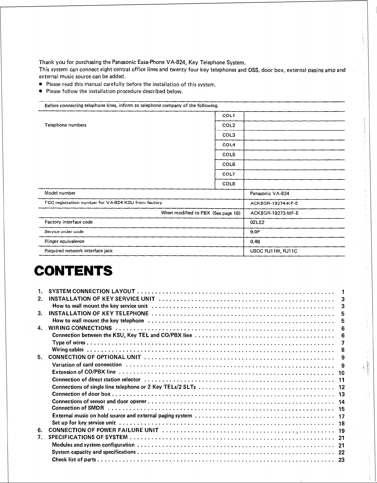
Thank you for purchasing the Panasonic Easa-Phone VA-824, Key Telephone System.
This system can connect eight central office lines and twenty four key telephones and DSS, door box, external paging amp and
external music source can be added.
l
Please read this manual carefully before the installation of this system.
l
Please follow the installation procedure described below.
Before connecting telephone lines, inform to telephone company of the following.
COLI
Telephone numbers COL2
COL3
COL4
COL5
COL6
COL7
COL8
Model number
FCC registration number for VA-824 KSU from factory
When modified to PBX (See page 18)
Factory interface code
Service order code
Ringer equivalence
Required network interface jack
Panasonic VA-824
ACK8GR-19274-KF-E
ACK8GR-19273-MF-E
02LS2
9.OF
0.4B
USOC RJI IW, RJl IC
CONTENTS
1. SYSTEMCONNECTIONLAYOUT .......................................................
2. INSTALLATION OF KEY SERVICE UNIT
How to wall mount the key service unit
3. INSTALLATIONOFKEYTELEPHONE ...................................................
How to wall mount the key telephone
4. WIRINGCONNECTIONS ............................................................. 6
Connection between the KSU, Key TEL and CO/PBX line
Typeofwires .....................................................................
Wiringcables..
...................................................................
5. CONNECTION OF OPTIONAL UNIT
Variation of card connection
Extension of CO/PBX line
..........................................................
............................................................
Connection of direct station selector
Connections of single line telephone or 2 Key TE Ls/2 SLTs
Connection of door box.
.............................................................
Connections of sensor and door opener.
Connection of SMDR
...............................................................
External music on hold source and external paging system
Set up for key service unit
............................................................
6. CONNECTION OF POWER FAILURE UNIT
7. SPECIFICATIONS OF SYSTEM
Modules and system configuration
System capacity and specifications.
Checklistofparts
..................................................................
.........................................................
....................................................... 21
...................................................... 22
.................................................
...................................................
....................................................
....................................... 6
.....................................................
..................................................... 11
...................................... 12
...................................................
....................................... 17
..................................... ‘-. ......... 19
1
3
3
5
5
7
8
9
9
10
13
14
15
18
21
23
Page 3
PROGRAMMING . . . . . . . . . . . . . , . . . . . . . . . . . . . .
. . . . . . . . . . . . . . . . . . . . . . . . . . . . . . . . . . . . . . .
24
INITIAL SET LIST.
1.
2. METHOD OF PROGRAMMING ............
3. PROGRAMMING ......................
System setting
PBX outside dialing digit ................ 30
Automatic pause ..................... 31
Call duration display appear timing ......... 32
Flash time .......................... 33
Pause time. ......................... 34
System speed dial group A ............... 35
System speed dial group B ...............
Long speech alarm .................... 37
COL auto answering ................... 38
COL night incoming ring mode ............ 39
Hold recall ......................... 40
Connection of door box. ................ 41
Type of applicable sensor ................
Sensor alarm stopping method ............ 43
Detection of SLT on-hooking ............. 44
Connection of DSS .................... 45
Hold recall for DSS TEL ................
Display time system setting .............. 47
SMDR output .......................
SMDR YEAR, MONTH and DAY setting
SMDR baud rate setting ................. 50
SMDR frame configuration.
Type of COL dialing
++ and #restriction
Digit length restriction .................. 54
Incoming call restriction ................ 55
Override setting ...................... 58
COL setting
Tone/pulse dialing signal conversion ......... 57
COlineorPBXline.. .................. 58
Automatic outside line selection group ....... 59
Length of DTMF signals. ................ 80
Minimum pause
Ring detection time
Key telephone setting
Telephone type
Line Key assign
Incoming call ringing
Off-hook signaling
Door box call
Sensor ringing ........................
Zone paging.
System speed dial group.
Flexible night service setting
Flexible night service
Outside dialing restriction class
System speed dial restriction
.......................... 57
.................... 25
........................ 30
..............
...................
....................
...................... 81
................... 82
...................
......................
...................... 84
................... 88
....................
........................
........................ 75
................
..............
................... 78
............ 79
.............. 83
27
30
38
42
48
48
..... 49
51
52
53
83
83
72
73
74
78
77
APPENDIX: Names and phone numbers list for system
speed dialing . . . . . . . . . . . . . . . . . . . 84
Programming table for initial set . . . . . . 85
Priority for simultaneous calling and
receiving . . . . . . . . . . . . . . . . . . . . . . 141
Tones and lamp indications. . . . . . . . - - 143
Page 4
1 89
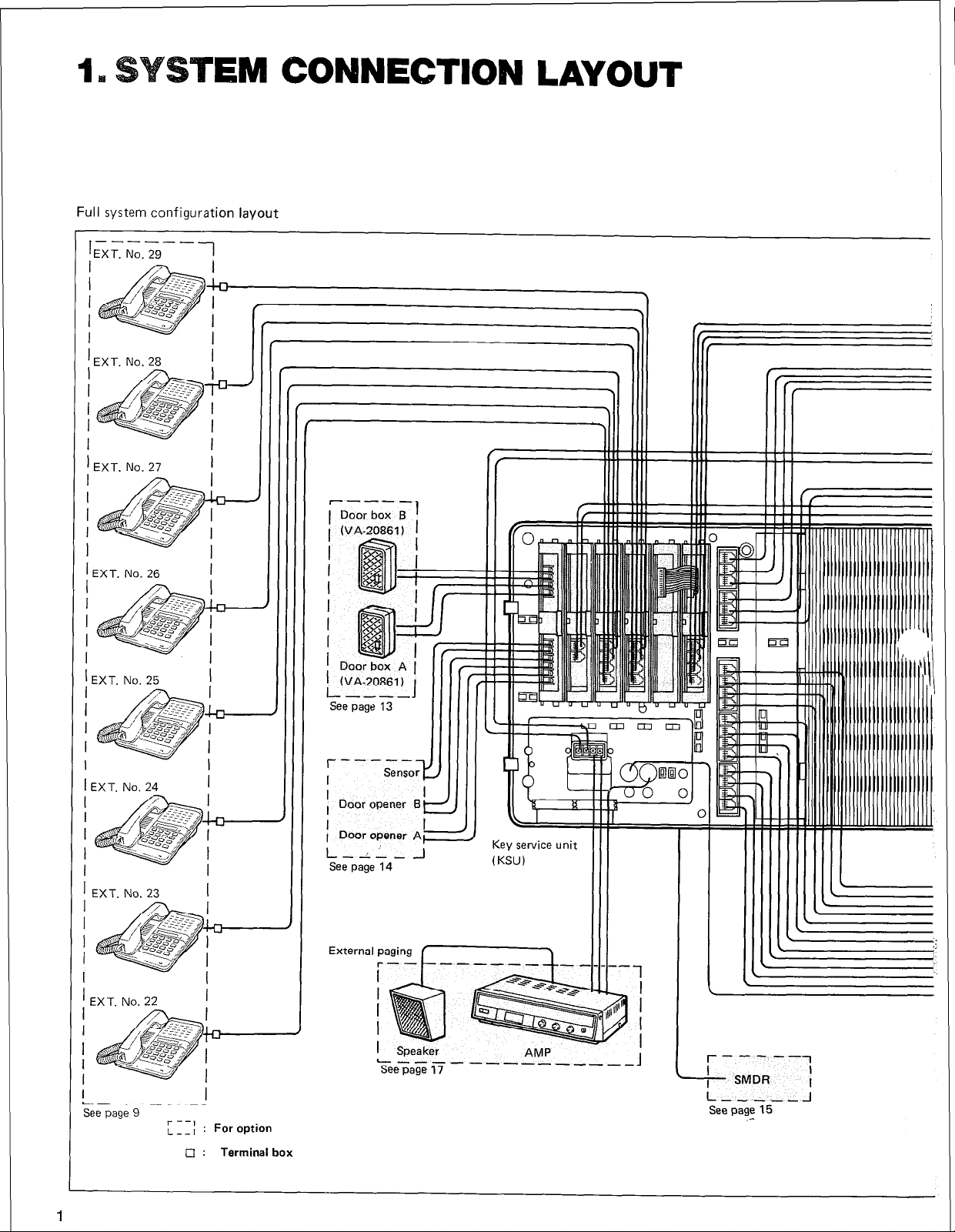
Full system configuration layout
EM CONNECTION LAYOUT
’ EXT. No. 28
I
I
I I
I I
1 EXT. No. 26
1 EXT. No. 25
i
I
l-J
I
I
I
-
1
I
EXT. No. 23
I
i_---_--
See page 9
I
I- --,
L--l
For option
•i : Terminal box
I
1 Door opener Al
I-- -I L--
See page 14
External paging f-1
1 Speaker
L---
Seepage,7 -----------A
I
J
Key service unit
(KSU)
AMP
r------l
I
L
- SMDR
L----J
See page 15
I
I
_-
Page 5
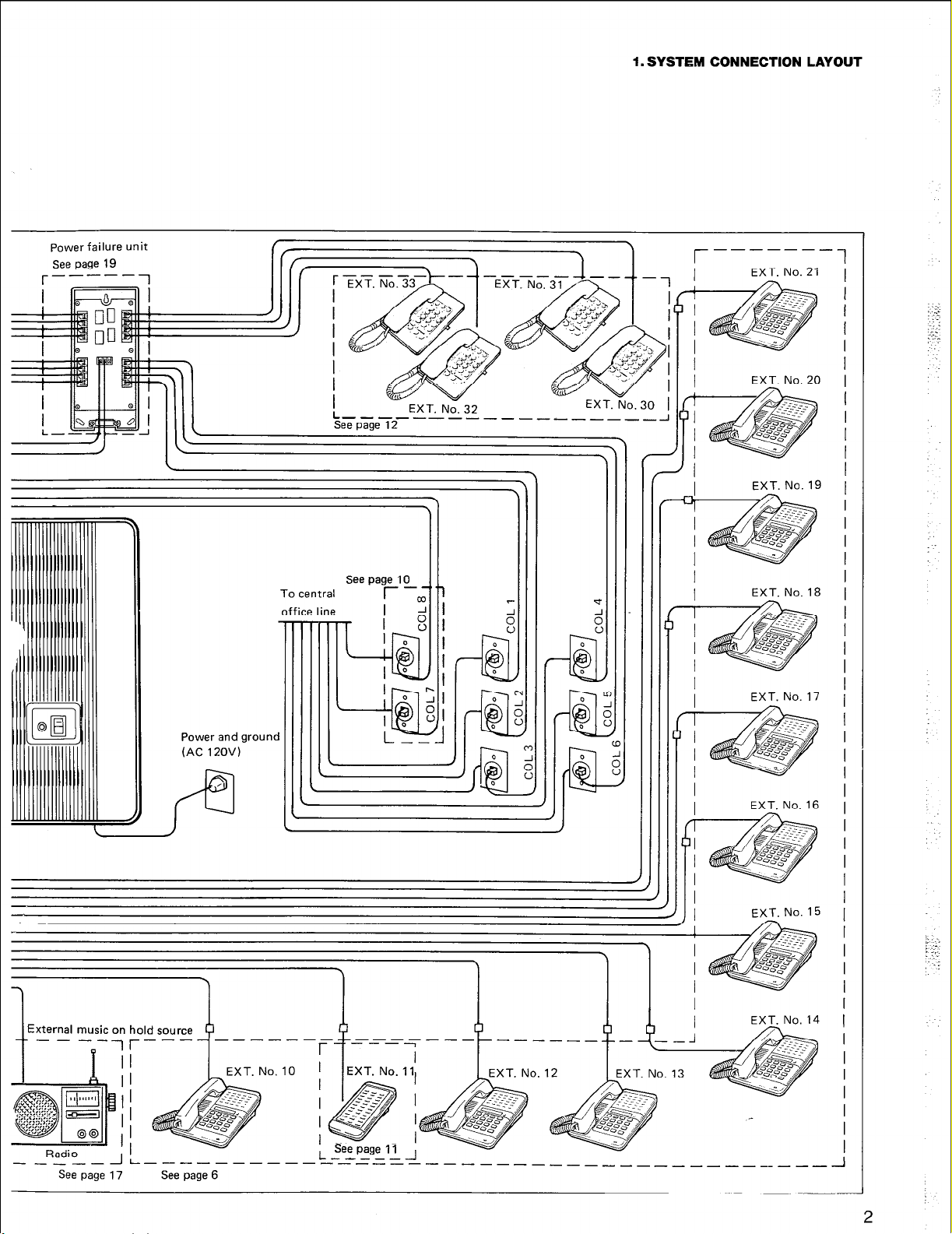
1. SYSTEM CONNECTION LAYOUT
Power failure unit
See page 19
To central
office line
EXT. No. 32
eT2 ----- ----- _____
See page 10
r -m
I 1 2
I
I
I
I
EXT. No. 21
EXT. No. 20
EXT. No. 17
Power and grounc
(AC 12OV)
I
4
External music on
I
+-----)
-___---- ___-----------------_____I
See page 17 See page 6
hold source
r---
3
----
I
--_---------- -I
EXT. No. 16
EXT. No. 15
-
2
Page 6
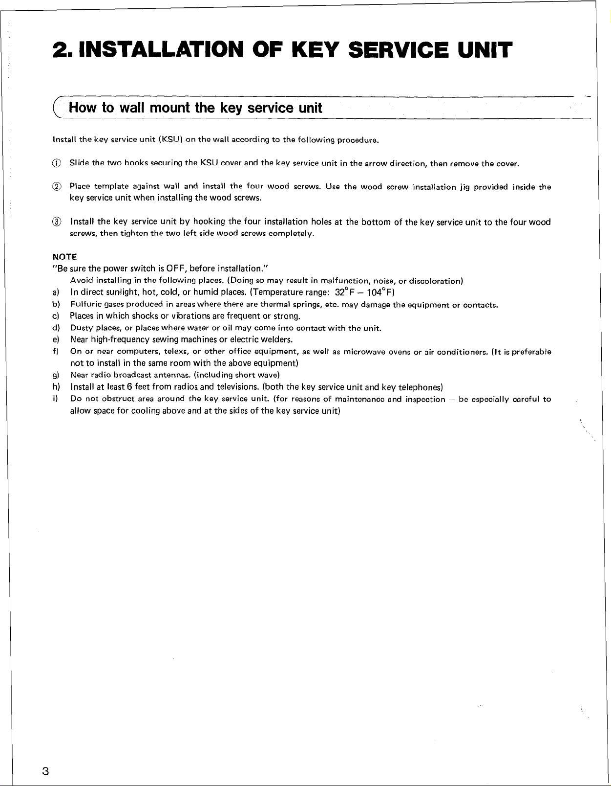
2. INSTALLATION OF KEY SERVICE UNIT
How to wall mount the key service unit
Install the key service unit (KSU) on the wall according to the following procedure.
@ Slide the two hooks securing the KSU cover and the key service unit in the arrow direction, then remove the cover.
@ Place template against wall and install the four wood screws. Use the wood screw installation jig provided inside the
key service unit when installing the wood screws.
@ Install the key service unit by hooking the four installation holes at the bottom of the key service unit to the four wood
screws, then tighten the two left side wood screws completely.
NOTE
“Be sure the power switch is OFF, before installation.”
Avoid installing in the following places. (Doing so may result in malfunction, noise, or discoloration)
a) In direct sunlight, hot, cold, or humid places. (Temperature range: 32’F - 104’F)
b) Fulfuric gases produced in areas where there are thermal springs, etc. may damage the equipment or contacts.
c) Places in which shocks or vibrations are frequent or strong.
d) Dusty places, or places where water or oil may come into contact with the unit.
e) Near high-frequency sewing machines or electric welders.
f) On or near computers, telexs, or other office equipment, as well as microwave ovens or air conditioners. (It is preferable
not to install in the same room with the above equipment)
g) Near radio broadcast antennas. (including short wave)
h) Install at least 6 feet from radiosand televisions. (both the key service unit and key telephones)
Do not obstruct area around the key service unit. (for reasons of maintenance and inspection - be especially careful to
i)
allow space for cooling above and at the sides of the key service unit)
3
Page 7
2. INSTALLATION OF KEY SERVICE UNIT
-I
Key service
Unit
Page 8
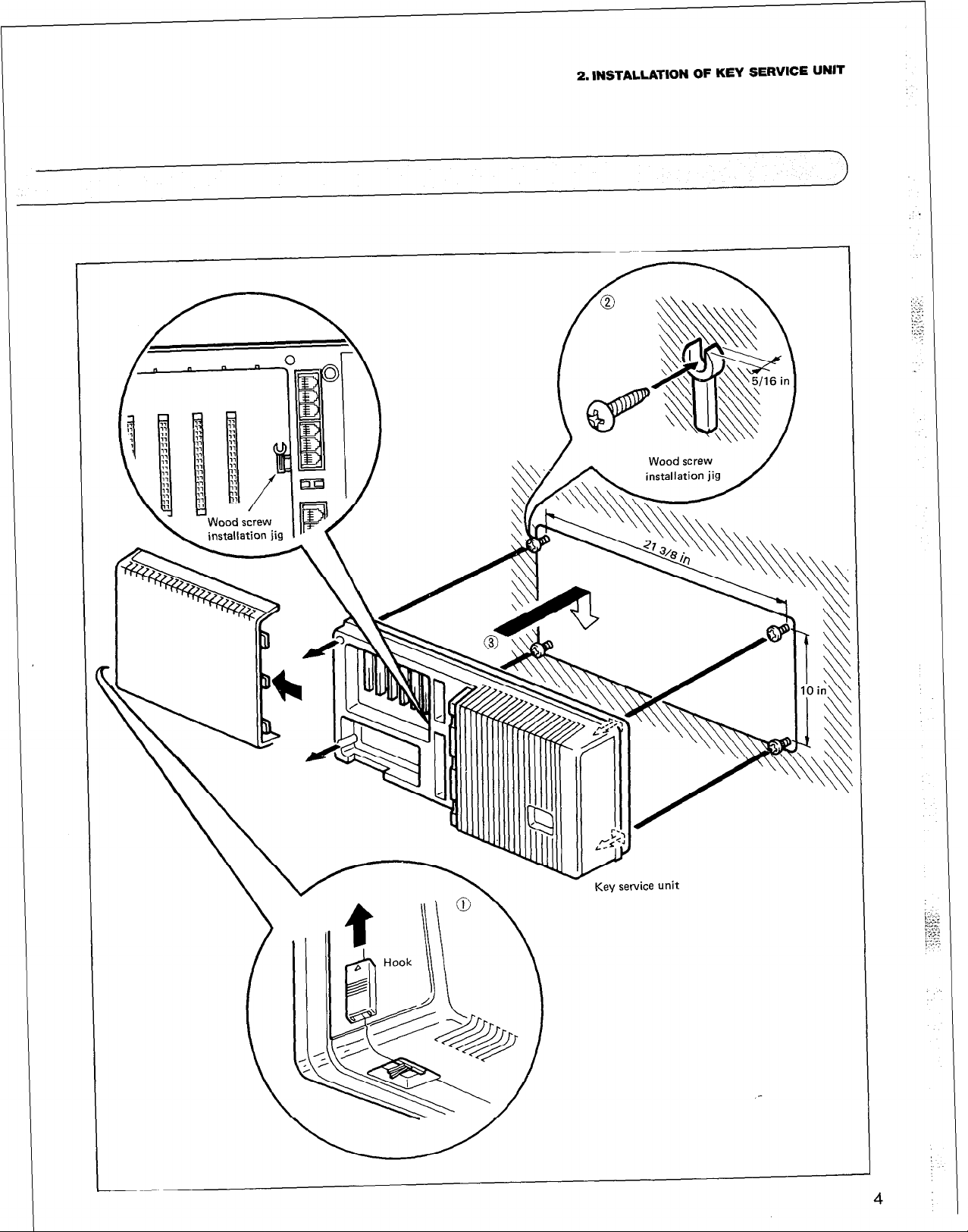
3. INSTALLATION OF KEY TELEPHONE
How to wall mount the key telephone
Install the key telephone on the wall according to the following procedure.
0 Pull handset guide, turn it upside
down, then insert it into its position.
@ Push the hooks at two places, then
remove the adapter.
@ Turn the adapter upside down, insert
the guides into two adapter mounting
holes provided at the lower portion of
the key telephone, then push in the
adapter.
@ Place the mounting holes of the
bracket over the studs of the modular
jack and pull the phone downward to
secure in place.
Short station cords are provided to
attach the key telephone.
NOTE
Handset cord obtainable on the market.
t MODEL NO. t LENGTH I
VAX-20884
VAX-20885
7 feet
15 feet
5
Page 9

4. WIRING CONNECTIONS
( Connection between the KSU, Key TEL and CO/PBX line
Make connections between the KSU, Key TEL and the central office/PBX line (CO/PBX) according to the following procedure.
0
Connection between the KSU and
CO/PBX line
Connect COL No. 1 through No. 6
jacks provided inside the KSU to the
CO/PBX line, respectively.
0
Connection between the KSU and Key
TEL
Connect EXT No. 10 through No. 21
jacks provided inside the KSU to the
key telephones, respectively.
EXT No. 10 is desirable to use an LCD
display type key telephone (VA-12022
or VA-12022-B) that is used for the
PROGRAMMING purpose described
later. (see page 28.)
TO the central
office lines
0 Clampring of cords
@ Push in the cables from the top of
the cable guide.
@ Remove the clamp plate, insert
the cords, then reinstall the clamp
plate over the cords and secure
into place with the screw.
NOTE
0
Keep the loop wire resistance to the
key telephone furthest from the key
service unit less than 40 ohms. (Max.
1100 feet with 22 AWG cable)
l
Do not wire the telephone cable in
parallel with the AC power source,
computer, telex etc. If the cables run
near those wires, shield the cables
within metal tubing or use shielded
cable and ground the shields.
l
When cables run on the floor, use protectors or the like to protect the wires
where they may be stepped on. Avoid
wiring under carpets.
0
When using an AC power supply (AC
12OV), make sure the unit is ground.
F
\v I\
to COL
_ COL6
COL5
COL4
COL3
COL2
COLI
c
Cl
lIIrIIIllII~
EXT. No. 21
IL
A
iL
AL
A
h EXT. No 1
EXT. No. 2(
,
EXT. No. l!
EXT. No. II
L
EXT. No. 1’
EXT. No. II
L
EXT. No. 1’
< EXT. No. l<
EXT. No. 1:
EXT. No. 1:
L
EXT. No. I,
r
to key telephone
6
Page 10
Type of wires
a
CONNECTION OF WIRING CABLE (FOR USE WITH A MODULAR CONNECTOR)
(a) If the key service unit and the exten-
sion are within 25 feet, use the cable
supplied (7 feet, 15 feet or 25 feet).
(See page 21)
(b) Station cord and Handset cord
Depending on the connection and
length, 4 types of station cords and 2
types of Handset cords are available.
(See page 21)
(c) When the key service unit and the
extension are apart by more than 200
feet, please use quad cable. Quad
cables assure proper operation over
long distance than flat cables.
In this case, use connector q (Modu-
lar-Screw).
0 Terminal Box
When coupling cables, either of the
following can be used (m or q ).
l
Flat cable
Flat cable obtainable on the market.
Optional cord
MODEL NO. LENGTH
VAX-20880
VAX-20881 7 feet
VAX-20882
VAX-20883
l
Quad cables explanation
l
Selecting quad cable depends upon the
wiring length.
l
Make sure that the quad cables are
twisted pair or shielded twisted pair.
Short station cord
(wall-mount only)
15 feet
25 feet
----_
---------
B MODULAR
cl
r
Ti
Brminal
Box
MODULAR
CONNECTOR -
CONNECTOR
TYPE
Terminal Modular
KSU
-
--
1
----__
MODULAR
CONNECTOR
- SCREW TERMINAL BOX
M Modular
--A---o
Key-TEL
+I
TERMINAL BOX
n
25 FEET
[Max option:
cord)
Quad cable
\ J
i
-----
200 FEET
(Max flat
cable)
s
Up to 1100 FEET
(Max quad cable)
(VAX-208861
Modular M Screw
ll
Note: Quad cables are not used for attach-
ing modular terminals.
7
NOTE
COUPLING
OF CABLE
Use the four conductor type
inline coupler.
Flat cable
Use this type when the quad cable
and door box unit is connected.
Flat cable Flat cable
Quad cable
Page 11
4. WIRING CONNECTION
Wiring cables
0 Be sure to connect as follows
Y:
YELLOW -
Connect the cables to the modular connector and modular screw terminal so that the wires Y, G, R and B at both ends of the
cable are parallel.
Note that there are no polarity indications (plus or minus) for outer pins B and Y and inner pins R and G.
CASE 1
Connection of modular connector and modular-screw terminal.
CASE 2
Connection to modular-screw terminal at both ends.
.,;a~;m+~*~~E;,,:,.
Modular-screw terminal Modular-screw terminal
l
Countermeasure for Lightning
For the outdoor wiring to prevent lightning hazard, connect the lightning protectors with TEL and KSU in such a
way that the distance between them can be kept short as
possible.
If telephone conversation is interrupted by lightning turn
off the POWER switch of KSU and turn it on again to see if
it works.
tar
Key TEL
For
Y
G
R
B
Gb ZNR = ERZClOK 391 GtiD
KSU
Y
G
R
B
8
Page 12
5. CONNECTION OF OPTIONAL UNIT
If you are not using key telephones other than those initially mounted, door boxes or external paging, you can disregard this
section.
Variation of card connection
For installing more telephones, three variations are available to connect station card as shown below. Extention Nos. are
indicated on each card depending on jacks.
CASE 1
Key TEL 24 pcs
SLT 0
CASE 2
Key TEL 22 PCS
SLT 2 pcs
Connector name of KSU
COL LCl LC2 LC3 LC-s
(cNod-)/mENxoT)JENxoT)(ENxoT)
8 25 29 31 33
7 24 28 30 22
CASE 3
Key TEL 20 pcs
SLT
4 pcs
DPH COL LCI LC2 LC3 LC-S
(4KT) (4KT) (4KT)
Station card I
(VA-30940)
9
DPH COL LCI LC2 LC3 LC-S
(4KT) (4KT) (2KT) (2SLT)
-Station Station
card I card Ill
WA-30940) (VA-30942)
--
DPH COL LC1 LC2 LC3 LC-S
I
(4KT) (4KT)
v-L_-
Station Station
card I card II
(VA-3094Or (‘/A-30941)
&XT)
Page 13
5. CONNECTION OF OPTIONAL UNIT
Extension of CO/PBX line
c
Be sure the power switch is off, before installing or removing the cards.
Make connections of an CO/PBX line card and to respective CO/PBX line according to the following procedure. When inserting
the CO/PBX line card, make sure that the card top and bottom ribs are aligned with the respective slots located at the regular
positions inside the key service unit.
l
Connection of CO/PBX line card WA-
82444)
Insert the CO/PBX line card into the
key service unit. This one card makes
two CO/PBX lines operable.
COL8
l
Connection of central office lines
Connect the central office lines to the
respective jacks on the card. COL
Nos. 8 and 7 assigned to the connectors in order from the top.
COL7
Page 14
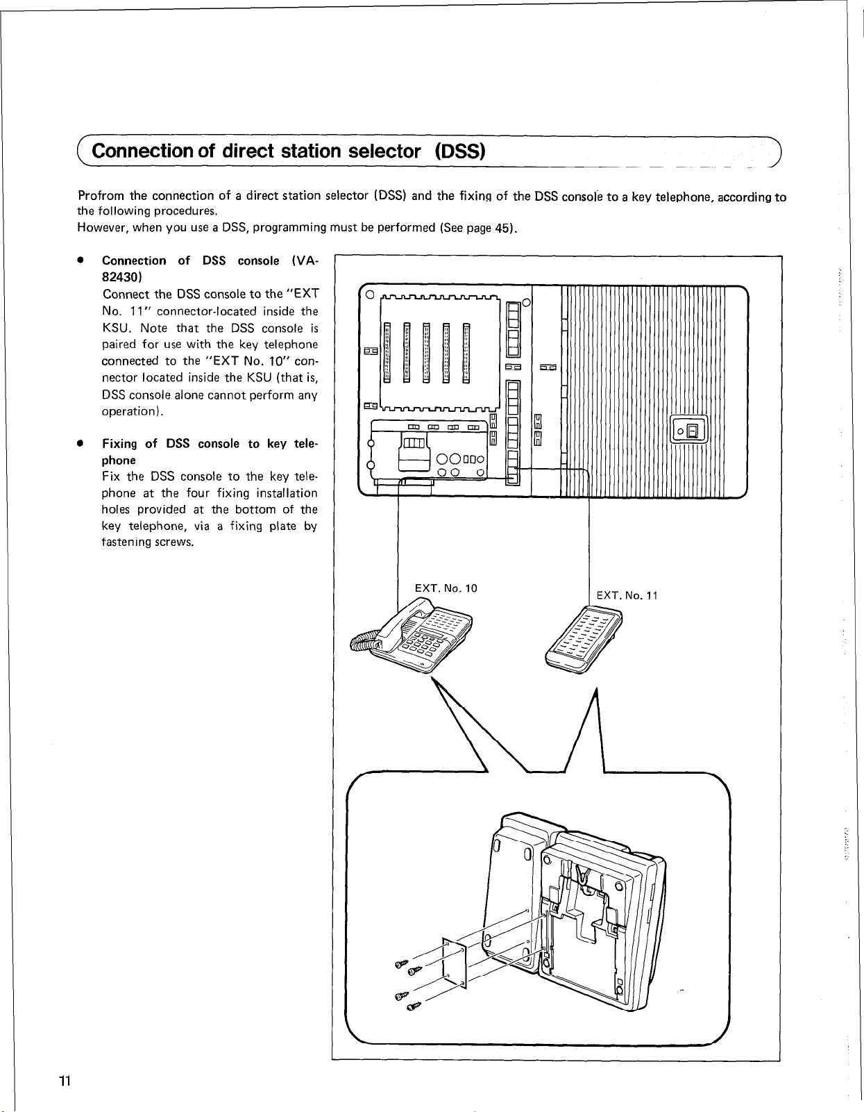
( Connection of direct station selector (DSS)
Profrom the connection of a direct station selector (DSS) and the fixing of the DSS console to a key telephone, according to
the following procedures.
However, when you use a DSS, programming must be performed (See page 45).
0
Connection of DSS console (VA-
82430)
Connect the DSS console to the “EXT
No. 11” connector-located inside the
KSU. Note that the DSS console is
paired for use with the key telephone
connected to the “EXT No. IO” con-
nector located inside the KSU (that is,
DSS console alone cannot perform any
operation).
0
Fixing of DSS console to key telephone
Fix the DSS console to the key telephone at the four fixing installation
holes provided at the bottom of the
key telephone, via a fixing plate by
fastening screws.
Page 15
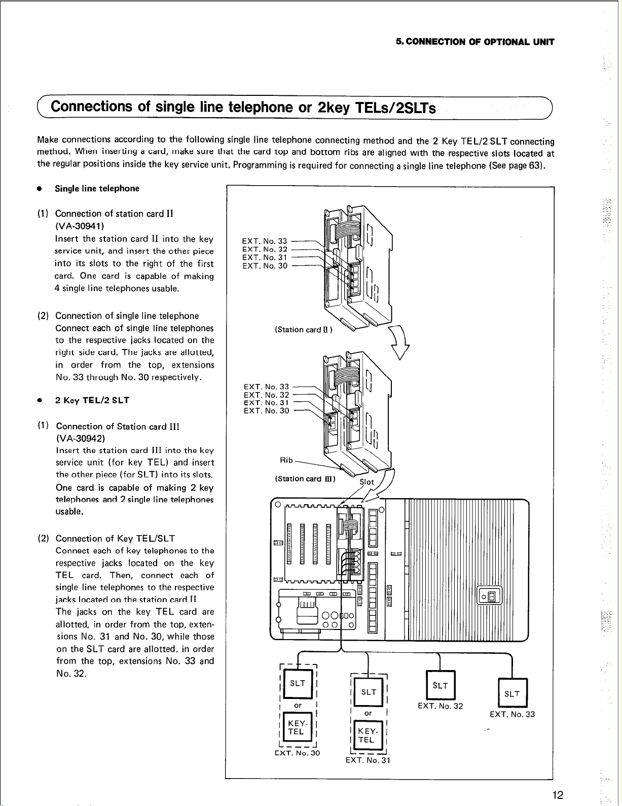
5. CONNECTION OF OPTIONAL UNIT
( Connections of single line telephone or 2key TELsl2SLTs
Make connections according to the following single line telephone connecting method and the 2 Key TEL/2 SLT connecting
method. When inserting a card, make sure that the card top and bottom ribs are aligned with the respective slots located at
the regular positions inside the key service unit. Programming is required for connecting a single fine telephone (See page 63).
0
Single line telephone
(1)
Connection of station card II
(VA-30941)
Insert the station card II into the key
service unit, and insert the other piece
into its slots to the right of the first
card. One card is capable of making
4 single line telephones usable.
(2) Connection of single line telephone
Connect each of single line telephones
to the respective jacks located on the
right side card. The jacks are allotted,
in order from the top, extensions
No. 33 through No. 30 respectively.
0
2 Key TEL/2 SLT
(1) Connection of Station card III
(VA-30942)
Insert the station card III into the key
service unit (for key TEL) and insert
the other piece (for SLT) into its slots.
One card is capable of making 2 key
telephones and 2 single line telephones
usable.
EXT. No. 31
EXT.
EXT.
EXT.
EXT.
(2) Connection of Key TEL/SLT
Connect each of key telephones to the
respective jacks located on the key
TEL card. Then, connect each of
single line telephones to the respective
jacks located on the station card II.
The jacks on the key TEL card are
allotted, in order from the top, exten-
sions No. 31 and No. 30, while those
on the SLT card are allotted, in order
from the top, extensions No. 33 and
No. 32.
[Jig; )q
EXT. No. 30
L--l
EXT. No. 31
EXT. No. 32
EXT. No. 33
Page 16
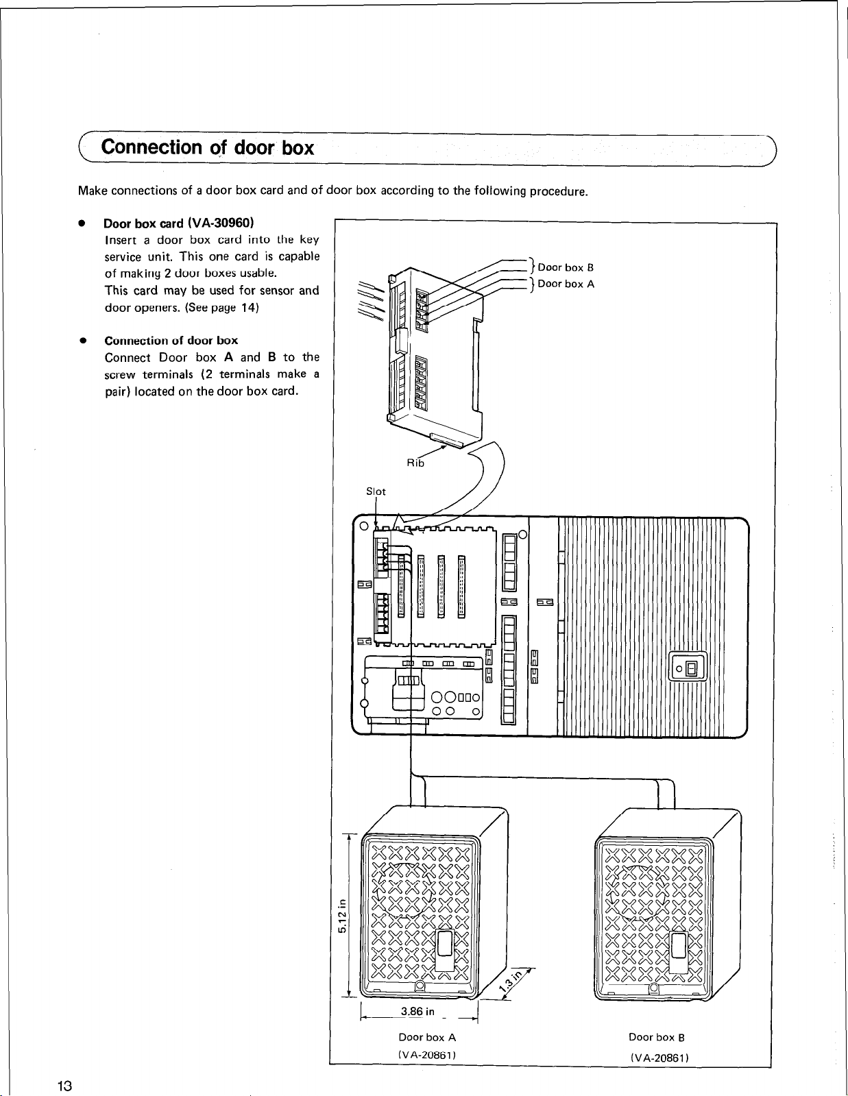
Connection Qf door box
Make connections of a door box card and of door box according to the following procedure.
l Door box card (VA-30960)
Insert a door box card into the key
service unit. This one card is capable
of making 2 door boxes usable.
This card may be used for sensor and
door openers. (See page 14)
l Connection of door box
Connect Door box A and B to the
screw terminals (2 terminals make a
pair) located on the door box card.
Door box 6
Door box A
13
3.86 in
Door box A Door box 6
(VA-20861)
(V~-20861)
Page 17
Connections of sensor and door opener
Make connections of sensor and door opener according to the following procedures.
l
Connection of sensor
(1) Insert a door box card (VA-30960)
into the key service unit.
This card makes sensor usable and also
be used for door box. (See page 13)
(2) Connect the sensor terminals (screw
terminals) on the door box card to
sensor to be used and must meet the
following requirements for connection.
Requirements for connection
(a) Always use a relay-type sensor.
(b) Ratings for contacts
See figure
5. CONNECTION OF OPTIONAL UNIT
-
Various sensor
Contact with-stand voltage
: MIN.5V
Contact current : MIN. 2 mA
Contact resistance : MAX. 0.1 n
l
Connection of door opener
(1) Insert a door box card (VA-30960)
into the key service unit. This one
card makes two door openers usable.
(2) Connect the screw terminals (two
terminals make a pair) located on the
door box card to the respective
door openers. Since the door openers
are one-to-one corresponding to the
door box, connections should be made
as shown below.
Door box A ff Door opener A
Door box B ++ Door opener B
Note that the door openers to be used
must meet the following requirements
for connection.
Requirements for connection (Re-
quirement for driving contacts of the
relay installed in KSU)
See figure
i-Ul
a0
-
OOC
C
-
-
-
1
Drive voltage
: MAXAC50VorMAXDC30V
Drive current
: MAX 1 A
Operation time
: Approximately 1 second
Goor opener w
14
Page 18
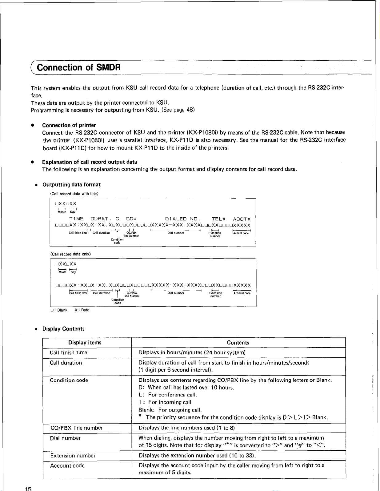
Connection of SMDR
This system enables the output from KSU call record data for a telephone (duration of call, etc.) through the RS-232C inter-
face.
These data are output by the printer connected to KSU.
Programming is necessary for outputting from KSU. (See page 48)
0
Connection of printer
Connect the RS-232C connector of KSU and the printer (KX-PI 08Oi) by means of the RS-232C cable. Note that because
the printer (KX-P1080i) uses a parallel interface, KX-PIID is also necessary. See the manual for the RS-232C interface
board (KX-PI 1 D) for how to mount KX-PI 1 D to the inside of the printers.
l
Explanation of call record output data
The following is an explanation concerning the output format and display contents for call record data.
l
Outputting data forma?
(Call record data with title)
-
uuuuxx:xxux:xx.xuxuuuxuuuuuxxxxx-xxx-xxxxuuuxxuuuuxxxxx
(Call record data only)
uxxuxx
HH
Month Da”
U : Blank X : Data
l
Display Contents
Call finish time
Call duration
Condition code
CO/PBX line number
Dial number
Extension number
Account code
TIME DURAT. C COr: DIALED NO. TEL4
Display items
Displays in hours/minutes (24 hour system)
Display duration of call from start to finish in hours/minutes/seconds
(1 digit per 6 second interval).
Displays use contents regarding CO/P8X line by the following letters or Blank.
D: When call has lasted over 10 hours.
L : For conference call.
I : For incoming call
Blank: For outgoing call.
* The priority sequence for the condition code display is D > L > I > Blank.
Displays the line numbers used (1 to 8)
When dialing, displays the number moving from right to left to a maximum
of 15 digits. Note that for display “*” is converted to I’>” and ‘:#‘I to “<,‘.
Displays the extension number used (10 to 33).
Displays the account code input by the caller moving from left to right to a
maximum of 5 digits.
ACCT f;
Contents
Page 19
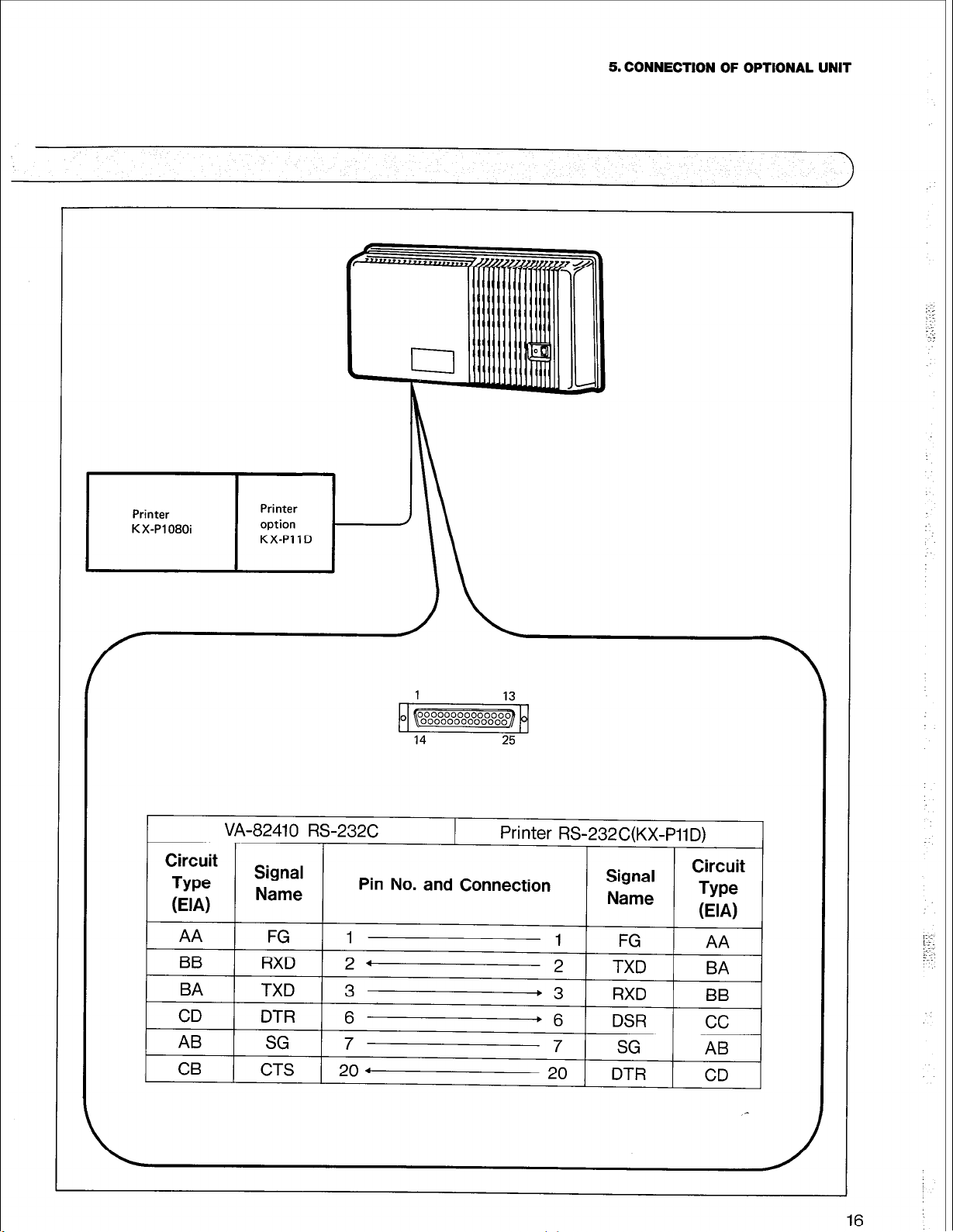
5. CONNECTION OF OPTIONAL UNIT
I
I
I
VA-8241 0 RS-232C
I I
Circuit
Type
EIN
AA FG 1
BB
BA TXD
CD
AB
1
CB
Signal
Name
RXD 2 .
DTR 6
SG 7
( CTS 1 20 4
14 25
Pin No. and Connection
3 .3
I
Printer RS-232C(KX-PilD)
Signal
Name
1 I,
2
-+6
7
20
TXD , -, ,
RXI-I 1
. ._.-
DSR
SG
DTR
Circuit
Type
(EIA)
RR
YY
cc
AB
CD
16
Page 20
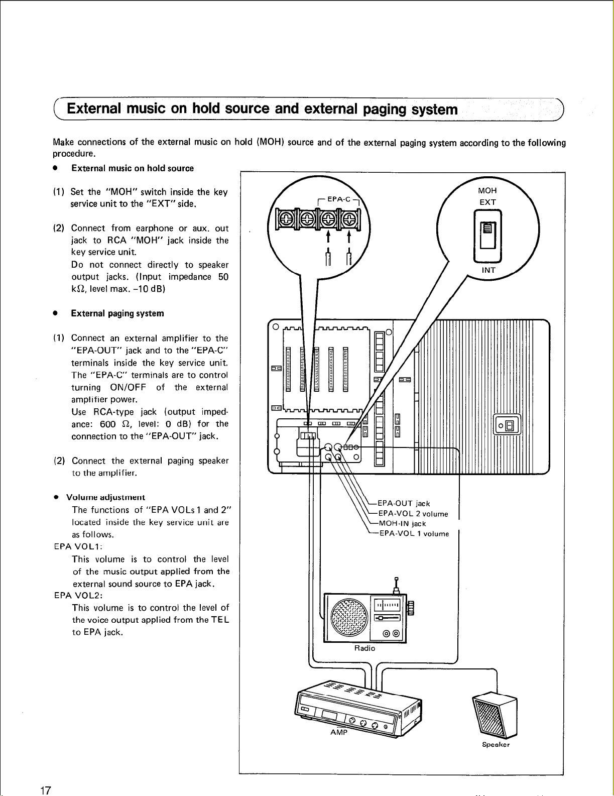
External music on hold source and external paging system
Make connections of the external music on hold (MOH) source and of the external paging system according to the following
procedure.
0
External music on hold source
(1) Set the “MOH” switch inside the key
service unit to the “EXT” side.
(2) Connect from earphone or aux. out
jack to RCA “MOH” jack inside the
key service unit.
Do not connect directly to speaker
output jacks. (Input impedance 50
ka, level max. -10 dB)
a
External paging system
) Connect an external amplifier to the
(1
“EPA-OUT” jack and to the “EPA-C”
terminals inside the key service unit.
The “EPA-C” terminals are to control
turning ON/OFF of the external
amplifier power.
Use RCA-type jack (output impedance: 600 a, level: 0 dB) for the
connection to the “EPA-OUT” jack.
(2) Connect the external paging speaker
to the amplifier.
l
Volume adjustment
The functions of “EPA VOLs 1 and 2”
located inside the key service unit are
as follows.
EPA VOLI :
This volume is to control the level
of the music output applied from the
external sound source to EPA jack.
EPA VOL2:
This volume is to control the level of
the voice output applied from the TEL
to EPA jack.
LEPA-VOL 1 volume
Radio
Speaker
17
Page 21
5. CONNECTION OF OPTIONAL UNIT
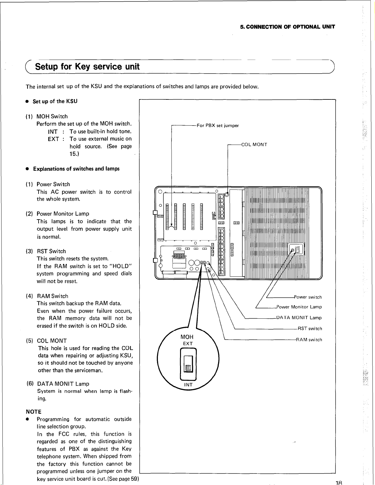
( Setup for Key service unit
The internal set up of the KSU and the explanations of switches and lamps are provided below.
l Set up of the KSU
(1) MOH Switch
Perform the set up of the MOH switch.
INT :
EXT :
To use built-in hold tone.
To use external music on
hold source. (See page
15.)
l Explanations of switches and lamps
( 1) Power Switch
This AC power switch is to control
the whole system.
(2) Power Monitor Lamp
This lamps is to indicate that the
output level from power supply unit
is normal.
rFor PBX set jumper
1
(3) RST Switch
This switch resets the system.
If the RAM switch is set to “HOLD”
system programming and speed dials
will not be reset.
(4) RAM Switch
This switch backup the RAM data.
Even when the power failure occurs,
the RAM memory
erased if the switch is on HOLD side.
(5)
COL MONT
This hole is used for reading the COL
data when repairing or adjusting KSU,
so it should not be touched by anyone
other than the serviceman.
(6) DATA MONIT Lamp
System is normal when lamp is flash-
ing.
NOTE
0
Programming for automatic outside
line selection group.
In the FCC rules, this function is
regarded as one of the distinguishing
features of PBX as against the Key
telephone system. When shipped from
the factory this function cannot be
programmed unless one jumper on the
key service unit board is cut.(See page 59)
data
will not be
I I
\ \ LEMTA
MoNIT
Lamp
18
Page 22
6. CONNECTION OF POWER FAILURE UNIT
Power Failure Unit (PFU) is optional equipment which, in case of power failure, directly connects CO/PBX lines and
Line Telephones.
0
Wall mounting method for PFU
@ Remove a PFU cover.
@ Install one wood screw on the wall remaining about 5/16 inches of the screw length unscrewed.
@ Hook the mounting hole provided at the top of the PFU to the on-wall installed wood screw, then fasten the wood screw
completely.
@ Install two wood screws on the wall through the two respective mounting holes provided at the bottom of the PFU.
l
Connection of PFU
(1) Connect the connectors labelled “FROM COL” (COL 1 to 4) and located inside the power failure unit to the respective
central office lines.
(2) Connect COL Nos. 1, 2, 3 and 4 inside the key service unit to the connectors (4 places from the top) labelled “TO COL
(KSU)” and located inside the power failure unit, respectively.
(3) Connect the connectors (4 places from the top) located on the card of the SLT card (right side card), which is set inside
the key service unit, to the connectors labelled “FROM SLT-LC(KSU)” and located inside the power failure unit, respectively.
Single
(4) Connect the connectors (TELs 1 to 4) labelled “TO SLT” and located inside the power failure unit to the respective single
line telephones. These connectors are allotted, in order from the top, Extensions Nos. 30,31,32 and 33.
(5) Connect the two screw terminals labelled “PFU” and located inside the key service unit to the respective two screw
terminals labelled “TO KSU” and located inside the power failure unit.
(6) Remove the clamp plate, insert the cords, then reinstall the clamp plate over the cords and secure into place with the
screw.
Note: That when power failure occurs the COLs correspond to EXTs as shown below.
COL I-+ EXT. No. 30
COL 2 -+ EXT. No. 31
COL 3 + EXT. No. 32
COL 4 + EXT. No. 33
19
Page 23

6. CONNECTION OF POWER FAILURE UNIT
16 in
EXT. No. 30
EXT. No. 31
EXT. No. 32
EXT. No. 33
to
SLT
Page 24

7. SPECIFICATIONS OF SYSTEM
Modules and system configuration
Note
VAX-20885 Handset cord (15 feet)
PITTSBURGH SALES OFFICE 0 Washington Circle, Bldg. #2. Rm. 202. 4150 Washington Rd., McMurrav, Pennsylvania 15317 l (412) 5618823
ATLANTA REGION l 1854 Shackleford Court, Norcross, Georgia 30093 l (404) 9256700
MIAMI REGION l 16115 N. W. 52nd Avenue, Miami, Florida 33014 l (305) 621-5814
DALLAS REGION l 1825 Walnut Hill Lane, Irving, Texas 75062 l (214) 550-1400
HOUSTON SALES OFFICE 0 15311 Vantage Parkway, W., Suite 200, Houston, Texas 66032 l (713) 590-3663
CHICAGO REGION l 425 East Algonquin Road, Arington Heights, lllnois 60005. (312) 364-7900
DETROIT REGION l 23923 Research Drive, Farmington, Michigan 48024 l (313) 477-2760
MINNEAPOLIS REGION 0 11001 Hampshire Avenue South, Bloomington, Minnesota 55438 l (612) 829COl9
ST. LOUIS REGION l 5434 Eagle Industrial Court Hazetwood, Missouri 63042 l (314) 731-1344
LOS ANGELES REGION l 6550 Katella Avenue, Cypress, California 90630 l (714) 895-7200
SAN FRANCISCO REGION l 3825 Hopyard Road, Pleasanton, California 94566 l (415) 463-2922
SEATTLE REGION l 4060 Lind Avenue S. W., Renton. Washington 98055 l (206) 251-5209
PORTLAND SALES OFFICE l 6645 N.E. 78 Court, Suite C-IO, Portland, Oregon 97218 l (503) 257-9661
DENVER REGION l 14401 East 33rd Place, Suite F, Aurora, Colorado 80011 l (303) 371-3080
PHOENIX SALES OFFICE 0 One Gateway Center 426 North 44th, Suite 473, Phoenix, Arizona 85008. (602) 273-0713
- -
21
Page 25

System capacity and specifications
System capacity
COL capacity
Intercom speech path
Key telephone*
Automatic dial
One touch dial
System speed dial
Speed dialing digits
Redialing digits
Specifications
Dimension (inch) (Height x Width x Depth) and Weight (Pound)
Key Service Unit
Key Telephone
Power Consumption (Watt)
8
4
Up to 24 (EXT. No. IO to 33)
10 stations (for each telephone)
90 stations (for the system)
16 digits/Station (included PBX access code)
16 digits/Last number and save number
12.6(H) x 23.0(W) x4.2(D), 9.5(lb)
8.5(H) x 6.7(W) x 2.4(D), 2.2(lb)
Maximum
*Note:
Approx. 130W
1. Specifications subject to change without notice.
2. Any of the below combination
a. 24 Key telephones
b. 22 Key telephones 81 2 single line telephones
c. 20 Key telephones & 4 single line telephones
Page 26
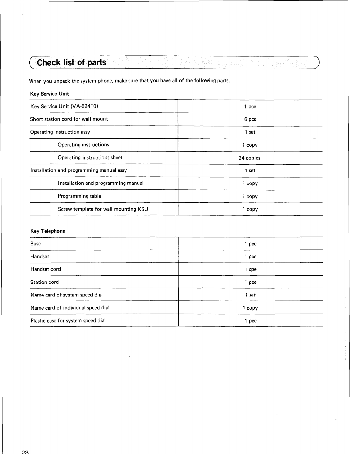
Check list of parts
When you unpack the system phone, make sure that you have all of the following parts.
Key Service Unit
Key Service Unit (VA-824101
Short station cord for wall mount
Operating instruction assy
Operating instructions
Operating instructions sheet
Installation and programming manual assy
Installation and programming manual
Programming table
Screw template for wall mounting KSU
Key Telephone
Base 1 pee
Handset
Handset cord
1 pee
6 pcs
1 set
1 COPY
24 copies
1 set
1 COPY
1 COPY
1 COPY
1 pee
1 cpe
Station cord 1 pee
Name card of system speed dial
Name card of individual speed dial
Plastic case for system speed dial 1 pee
1 set
1 COPY
Page 27
EXPLANATION ON PROGRAMMING
The Easa-Phone VA-824 is a small, sophisticated Key Telephone system. It offers many features which can be easily programmed to uniquelly fit your communication needs.
The Easa-Phone utilizes Random Access Memory (RAM) for storage of the “User’s”
telephone station can be assigned a set of features based on the individual “User’s” requirements.
Note that a program has been preset into the Easa-Phone VA-824 system memory for general use which is called the Initial
Set. Thus, no programming is necessary to immediately use your telephone system. However, to properly change from the
Initial Set to any other option, the programming steps detailed under the Programming Settings for the desired feature must be
followed.
A programming record chart is provided for ease of recording your program changes. A sample of this Programming Table
indicating the initial Set can be found in the back of this manual. Whenever programming changes are made, they should be
immediately recorded on the Programming Table to provide a quick reference of the current programmed feature options.
variable programs and features. Each
PROGRAMMING CONTENTS
INITIALSETLIST
1.
2. METHOD OF PROGRAMMING
3. PROGRAMMING ...................................................................
APPENDIX ..........................................................................
..................................................................
.........................................................
25
27
30
84
24
Page 28
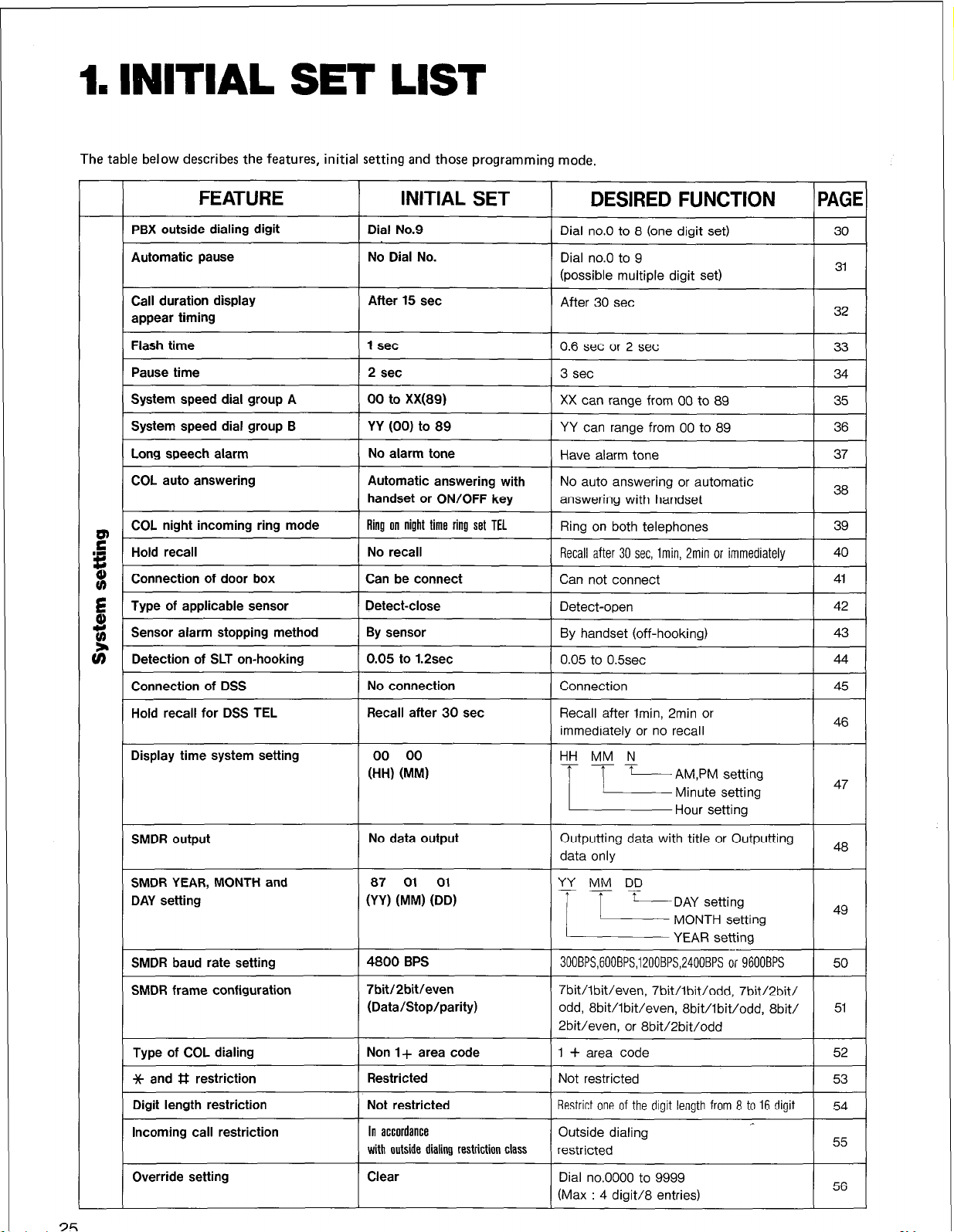
1.
INITIAL SET LIST
The
table
below describes the features, initial setting and those programming mode.
FEATURE
PBX outside dialing digit
Automatic pause
Call duration display
appear timing
Flash time 1 set
Pause time
System speed dial group A
System speed dial group B
Long speech alarm
COL auto answering
COL night incoming ring mode
Hold recall No recall
Connection of door box 1 Can be connect
Type of applicable sensor
Sensor alarm stopping method
Detection of SLT on-hooking 0.05 to 1.2sec
Connection of DSS
Hold recall for DSS TEL Recall after 30 set
Display time system setting 00 00
INITIAL SET
I
Dial No.9
No Dial No.
After 15 set
2 set
00 to Xx(89)
YY (00) to 89
I ~ ~~
No alarm tone
Automatic answering with
handset or ON/OFF key
1 Ring on night time ring set TEL
Detect-close
By sensor
No connection
(HH) (MM)
DESIRED FUNCTION
Dial no.0 to 8 (one digit set)
0.6
set or 2 set
3 set
XX can range from 00 to 89
YY can range from 00 to 89
No auto answering or automatic
11
Recall after 30 set, lmin, Pmin or immediately
Can not connect
Detect-open
By handset (off-hooking)
0.05
to 0.5sec
Connection
Recall after lmin, 2min or
immediately or no recall
HH MM N
IPAGEI
I 33 I
I 34 I
I 35 I
1 36 1
I 40 I
41
I I
I 42 I
43
44
45
46
25
SMDR output
SMDR frame configuration i’bitI2bitIeven
Type of COL dialing Non l+ area code
Jc and # restriction 1 Restricted
Digit length restriction
Incoming call restriction
Override setting Clear
No data output
(Data/Stop/parity)
Not restricted
In accordance
with outside dialing restriction class
11
Outputtrng data wrth title or Outputtmg
300BPS,600BPS,1200BPS,24OOBPS or 96OOBPS
odd, 8bit/lbit/even, 8bit/lbit/odd, 8biV
2bit/even, or 8bit/2bit/odd
1 + area code
Not restricted
Restrict one of the digit length from 8 to 16 digit )
I 52 I
I 53 I
54 )
Page 29
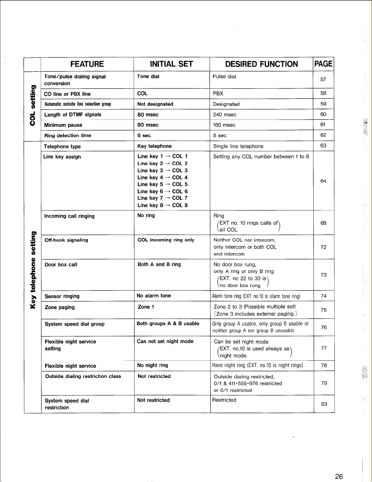
Incoming call ringing
.F
.I
Off-hook signaling
t:
8
g
Door box call
c”
B
al
w
Sensor ringing
z
* Zone paging
System speed dial group
Line key 3 ----f COL 3
Line key 4 + COL 4
Line key 5 + COL 5
Line key 6 ---f COL 6
Line key 7 + COL 7
Line key 8 + COL 8
No ring
COL incoming ring only
Both A and B ring
No alarm tone
Zone 1
Both groups A & B usable
Ring
EXT no. 10 rings calls of
all COL
c
68
Neither COL nor intercom,
only intercom or both COL 72
and intercom
No door box rung,
only A ring or only B ring
EXT. no 22 to 33 is
no door box rung
c
1
73
Alarm tone ring (EXT. no.10 is alarm tone ring) 74
Zone 2 to 3 (Possible multiple set)
(Zone 3 includes external paging.)
Only group A usable, only group B usable or
75
76
neither group A nor group B unusable
Flexible night service
setting
Flexible night service
Outside dialing restriction class
System speed dial
restriction
Can not set night mode
No night ring
Not restricted
Not restricted
Can be set night mode
EXT. no.10 is used always as
night mode.
i
1
Have night ring (EXT. no.10 is night rings)
Outside dialing restricted,
O/l & 411-555-976 restricted
or O/l restricted
Restricted
77
78
79
83
26
Page 30

2. METHOD OF PROGRAMMING
Read the following paragraphs before proceeding to the actual programming instructions and procedures.
These notes and procedures are intended to acclimate the programmer to the proper programmingsequencerequired prior to
the actual programming.
0
Programming of initial set
@ Assure that the RAM switch is posi-
tioned at “CLR” side.
@ Set the power switch to the “ON”
position.
@ After about 5 seconds, assure that the
DATA MONIT lamps is flashing.
@ Change the RAM switch from the
“CLR” side to “HOLD” side.
The initial set programming is now completed through the above operations.
NOTE
If you change the programming again,
the RAM switch is not necessary
switched over.
27
Page 31

l
Method of programming
All programming changes are made at
Extension No. 10 and it is recommended to use key telephone with a LCD
display (VA-l 2022 or VA-12022-B).
2. METHOD OF PROGRAMMING
@ Press the ON/OFF button. The
OFF indicator and MIC indicator
lights up and a continuous tone is
emitted.
@ Press the p] p] p][o](The continuous
tone will stop) and then press the dial
ON/
keyrjiJm1 (X: mode numbers 1 to 7)
mode 1: System setting
mode 2: COL setting
mode 3: Key telephone setting
mode 4: Incoming call ringing setting
mode 5: Line/FF key setting
mode 6: Restriction setting
mode 7: Display time setting
@ Press the program step numbers for
the desired feature option. Refer to
the PROGRAMMING TABLE for
programmable feature option.
Press the
0
ry. The next program step will appear
on the LCD display. When mode
numbers of the programming features
to be changed are the same, program
step numbers of the programmings to
be changed can be input after the
registration. Therefore, the programm-
ing changes can be performed continu-
ously for the programming features
having the same mode number.
q
key to store the memo-
MIC indicator
LCD display
ON/OFF Button
ON/OF; indicator
@ Press the ON/OFF button and display
will return to the clock mode (ON/
OFF indicator and MIC indicator will
go off).
l
Mode confirmation
If you want to confirm the mode num-
ber during programming, you can do
so with the LCD display by inputting
qqiiq~5~~~ ‘I.
28
Page 32

flowchart
A
YES
Complete
I
I
1
ON/OFF key
x 000
c
Input of mode No.
4
# key
4
T
Programming for each mode
I
(Set up for program mode)
Jj
’ (Mode set)
1,
29
I
T
ON/OFF key
/
+
I
7
# key
4
Increment of
program step No.
I
I
Page 33

MODE I
( System setting
PBX outside dialing digit
You can have access to an outside line through PBX. This feature is necessary when the system is connected to PBX. Set
by specifying one digit from among dialing numbers 0 to 9 (PBX line access number ).
Key Operation LCD indication
Program
mode
Program
step [ m @ m m
Remarks
Desired
program
mode
Storing
command
Dial No.
- 0 thru 9 can be programmed.
Initial setting is 9.
30
Page 34

Automatic pause
You can place a pause automatically after the first digit dialing number when having access to outside numbers through PBX.
Set by specifying one digit from among dialing numbers 0 to 9 (PBX line access number ).
MODE
Program
mode
Program
step
Key Operation
LCD indication
Remarks
Desired
program
mode
End
L
-0 thru 9 can be programmed.
ON/Off
I
El
Page 35

Call duration display appear timing
MODE I
When making an outside call by a key telephone with an LCD display, you can set how many seconds after completion of
dialing you want the conversation time to appear on the display.
Program
mode
Program
step
Key Operation
LCD indication
Remarks
Desired
program
mode
Storing
command
After 15 set
(Initial)
. . . . . . . . . . . . . . . .
After 30 set
or ,
-1J
!ON/
$
:OFF
cm3 ’
cl03
t
ON1
I
OFF
cl
4
1 I
-Either 0 or 1 depending on the
desired program mode.
32
Page 36

Flash time
MODE I
You can set the length of open time for an outside line with FLASH key and that of auto-flash time with REDIAL key function.
When you wish to use the call waiting service, just press FLASH key.
If the system is connected to the PBX line and you do not use the hold function of PBX system, set to 2 seconds.
Program
mode
Key Operation
0.6 set
or
0
KJ
. . . . . . . . . . . . . . . . . . . . .
LCD indication
J
c 189
Remarks
0)
Desired
program
mode
Storing
command
1 set (
..I...,.....,,,,
2sec
‘Initial)
ON ‘Off
m
a
1
c 1UY
1 I
-Either 0, 1 or 2 depending on
the desired program mode.
33
Page 37

Pause time
MODE I
By pressing
digit. This is used when you need to wait for a second dial tone when dialing an outside line.
Program
mode
REDIAL
key, a pause can be stored in the system speed memory and one-touch key. One pause is counted as one
Key Operation
LCD indication Remarks
Desired
program
mode
Storing
command
End
2sec
(Initial)
. . . . . . . . . . . . . . . . . .
3sec
r
I
I
0
fzl
or . . . . . . . . . . . . . . . . . . . . . .
1
m
#
RI
c 105 I i
+ i
Either 0 or 1 depending on the
desired program mode.
,..
/ :.
:‘,.:
.:
Page 38

System speed dial group A
You can divide the system speed dial memory into two groups. The range of address numbers for group A is from 00 to XX.
XX is the last address number of the range and the designation should be between 00 to 89.
MODE I
Program
mode
Key Operation
u
LCD indication
4
Remarks
Desired
program
mode
Storing
command
End
System speed
Dial No.
I
Initial setting is 89.
ON1
OFF
Page 39

MODE I
System speed dial group B
You can divide the system speed dial memory into two groups. The range of address numbers for group B is from YY to 89. YY is
the first address number of the range and the designation should be between 00 and 89.
Program
mode
Key Operation LCD
.
indication Remarks
Desired
program
mode
Storing
command
End
System speed
Dial No.
f
’
/
f
Program the first number of the
Initial setting is 00.
36
Page 40

Long speech alarm
When making an outside call, you can set SO that a short alarm tone sounds from the speaker every three minutes.
MODE I
Program
mode
Key Operation
r
No alarm tone
LCD indication
Remarks
Desired
program
mode
Storing
command
End
(Initial)
, . . . . . . . . . . . . . . . . . or *...................
Have alarm tone
f
c 108
d
Either 0 or 1 depending on the
desired program mode.
37
Page 41

COL auto answering
MODE I
You can answer incoming calls without pressing Line key. There are two systems for answering: one is to simply lift the handset
and the other is either to lift the handset or press ON/OFF key.
Key Operation LCD indication Remarks
Program
mode
Program
step
Desired
program
mode
Storing
command
1 m m m m
No auto answering
. . . . . . . . . . . . . . . . . or . . . . . . . . . . . . . . ...**...
On1 handsef
aut answering
X
. . . . . . . . . . . . . . . . . or . . . . . . . . . . . . . . . . ..i***
Handset & ON/OFF key
(Initial)
I
0
K!
1
m
c 109
c 109
.
31
1 I
_-Either 0, 1 or 2 depending on the
desired program mode.
End
I
1[Eq,[E-] :
38
Page 42

COL night incoming ring mode
You can specify telephones to ring in case of night time incoming calls in systems programmed for this purpose . This is
necessary when the places for receiving incoming calls are different at daytime and night time.
MODE 1
Program
mode
Key Operation
Only night time ring
set TEL will ring.
(Initial)
. . . . . . . . . . . . . . . . . . or . . . . . . . . . . . . . ..*......
0
&!I
LCD indication
cl10 0
Remarks
Desired
program
mode
Storing
command
39
COL ring set TEL
will ring,too.
I
I
t
I :
Either 0 or 1 depending on the
desired program mode.
_-
cl10 1 i
Page 43

Hold recall
You can set a telephone so that a warning tone sounds once a certain period has elapsed after a call has been put on hold.
Hold recall can be disabled, or set for immediately, 30 seconds, 1 minute or 2 minutes.
MODE I
Program
mode
Program
step
Key Operation
ON/N
m
@!I mvm m
.
LCD
indication Remarks
Desired
program
mode
After 2 min
pEY-jyI
7 i
command , 3 , ,?’ , , i
f
Storing
End I
,
/
Either 0,
1,
2, 3
or 4 depending onthedesiredprogrammode. i$
,-
ji-
40
Page 44

Connection of door box
MODE I
Up to two door boxes can be used with this system by connecting the door box card to KSU. You can set it so that the signal
from the door box is heard or not heard through a telephone which has been programmed in advance.
You do not have to change the programming if door box is not connected.
Program
mode
Can not connect
KJ
0
LCD indication
Remarks
Desired
program
mode
Storing
command
. . . . . . . . . . . . . . . . .
Can be connect
(Initial)
f
or
. . . . . . . . . . . . . . . . . . . . . .
r
L
-
/
Either 0 or 1 depending on the
desired program mode.
41
Page 45

Type of applicable sensor
Two types of sensor can be used by connecting the door box card to KSU. An alarm will sound from a telephone which has been
programmed in advance. The operating method for these sensors is specified either as close detection or open detection.
MODE I
Program
mode
Program
step
Key Operation
on/m
m
b!!l m’m IEJ
m-m
Detect - close
(Initial)
. . . . . . . . . . . . . . . . . .
or . . . . . . . . . . . . ..*.......
LCD indication
.
d
c 113
Remarks
‘I 01
Desired
program
mode
Storing
command
End I
Detect - open
.
o-
c 113
4
t
-Either 0 or 1 depending on the
desired program mode.
42
Page 46

Setisor alarm stopping method
You can specify the method for stopping the sensor alarm. This specification can be that either no alarm sound is given from
the sensor or that the alarm sound is stopped by lifting the handset of alarmed telephone.
MODE I
Program
mode
Program
step
Key Operation
By sensor
(Initial)
,. . . . . . . . . . . . . . . . . or
0
HI
. . . . . . . . . . . . . . ...**...
LCD indication
c 1 w
01
Remarks
Desired
program
mode
Storing
command
End
43
I-
I
By handset
(Off-hooking) CllY / 1
I
P
Either 0 or 1 depending on the
desired program mode.
I .
I .
Page 47

Detection of SLT on-hooking
MODE I
When you want to hold an outside line with SLT, press hook switch breifly.
If the hooking time is longer than the time which programed,the phone line will be disconnected. If you do not use frequently
hold function, this hooking time should be set to less than 0.5 second.
Program
mode
Program
step
Key Operation
mfmr
la
k!J m’m El
0.05 to 0.5 set
0
K!l
LCD indication
\
c 1 IS
Remarks
01
Desired
program
mode
Storing
command
End
. . . . . . . . . . . . . . . . . or . . . . . . . . . . . . . . . . . . . . .
0.05 to 1.2 set
(Initial)
f
I
1
m
-Either 0 or 1 depending on the
desired program mode.
1 [E-] + [iq
Page 48

Connection of DSS
This feature is to program connection of the DSS.
For setting in “Connection”, DSS should be connected to EXT.No.11 jack of KSU.
MODE I
Program
mode
Program
step
Key Operation
No connection
(Initial)
. . . . . . . . . . . . . . . , . . or
. . . . . . . . . . ..I.........
LCD indication
c/:6
,:, 01
Remarks
Desired
program
mode
Storing
command
End
Connection
I
f
#
ml
ONAM
RI
l!iJ
1
c I :6
I 1 :
I
I
Either 0 or 1 depending on the
desired program mode.
45
Page 49

MODE I
Hold recall for DSS TEL
You can set a telephone so that a warning tone sounds once a certain period has elapsed after a call has been put on hold.
Hold recall can be disabled, or set for immediately, 30 seconds, 1 minute or 2 minutes.
Program
mode
Key Operation LCD indication
ON ‘Olf
m
c::: ’ u”
Remarks
I
Desired
program
mode
Storing
command
End
clw ’ 3 i
After 2 min
-Either 0,1,2,3 or 4 depending on
, , ~ I : 8 u” , ; the desired program mode
f
#
IL3
/
0
46
Page 50

Display time system setting
This feature is for setting the correct time for a key telephone with an LCD display.
Program
mode
Program
step
m &g m pJ pExq:
Key Operation
LCD indication
/
Remarks
AM : 12:OO is for night.
PM : 12:OO is for daytime.
Desired
program
mode
Storing
command
End
47
f
.-
Page 51

SMDR output
This feature is to program to output data onto the SMDR printer.
This is necessary when you want to notify the call record.
You can set for not outputting SMDR data, outputting the data with the title or outputting the data only.
MODE 7
Program
mode
Program
step [[
Desired
program
mode
Key Operation LCD indication
No data output
,........ I.......: nr
,. . . . . . . . . . . . . . . . . or
(Initial)
. . . . . . . ...*..
Outputting data
with title
. . . . . . . . . . . . .
Outputting data only
.
El
-
1
Remarks
cf?OI 3
I
CiW
I
3
I
Storing
command
End
1 ‘i
Either 0, 1 or 2 depending on the
: desired program mode
I
,-
48 :
Page 52

MODE 7
SMDR YEAR, MONTH and DAY
This feature is to program to set Year / Month / Day as SMDR print data.
setting
Key Operation LCD indication Remarks
Program
mode
Desired
program
mode
Storing
command
49
Page 53

SMDR baud rate setting
This feature is to program the baud rate of output data to the SMDR printer.
MODE 7
Program
mode
Key Operation LCD indication
300 BPS
II.I.I....III..
or
c 203 :
Remarks
I
Desired
program
mode
Storing
command
600 BPS
,...............
1200 BPS
I..,.,..,.,....,
2400 BPS
,**.***.........
4800 BPS
I.......,,,.....
9600 BPS
r
I
r
or
or
or
or
El
m
,..........
Either 1,2,3,4, 5 or 6 depending
on the desired program mode
#
ON/llA
[El -b [E-l
3
50
Page 54

MODE 7
SMDR frame configuration
This feature is to program the frame configuration of output data to the SMDR(Data length/ Stop bit length/ Parity check bit
number).
Program
mode
Desired
program
mode
Key Operation LCD indication
QN/Mf
L!l
lE!l llTE!rm E!l
-5
r
7 bit /1 bi; / Even number
II .,,,.. . . ..,... .,. or *..........
7 bit / 1 bit I Odd number
. . . . , , , . . . . . . , , . . . or .*..,,,,.*.
7 bit / 2 bit / Even number (Initial)
,......, . . . . . . . . ,.. or . . . . ..I....
7 bit I2 bit I Odd number
,.....,. I* . . . . . . . . . or . . . . . . ..I..
8 bit / 1 bit I Even number
,..,,,.. . . . . . . . . . . . or . . . . . . ..I..
8 bit / 1 bit /Odd number
. . . . , , , . . , . . . , , . . . .*.**.,,..*
8 bit / 2 bit / Even number
.,...., . . . . . . . . . . . or . . . . . . . . ..I
8 bit / 2 bit/Odd number
or
Remarks
(
c
Storing
command
End
51
-2
f
#
&!I
‘~
/
Either 1,2,3,4,5,6, 7 or adepending on the desired program mode
Page 55

Type of COL dialing
MODE 6
This program is required when the extension is set to outside dialing restriction classes 2 or 3. When
it specifies whether or not the area requires “1” before dialing the number.
Key Operation LCD indication
Program
mode
you
are
making
Remarks
an outside call,
Desired
program
mode
Storing
command
End
Non 1 + area code
(Initial)
. . . . . . . . . . . . . . . . or
1 + areacode
f
r
I
L2l
. . . . . . . ..I............
ON/OFF
La
0
Either 0 or 1 depending on the
desired program mode.
\
1
1
52
Page 56

++ and
In case of outside dialing restriction classes 2 and 3, calls can be restricted by inputting the* or#key while dialing an outside
line. The setting specifies whether there is to be a restriction or not.
# restriction
MODE 6
Program
step
Key Operation
Restricted
(Initial)
,. . . . . . . . . . . . . . . . . or
0
Ia
. . . . . . . . . . . ..*........
LCD indication
I
I
cuiu2
Remarks
0 I j
1 :
Desired
program
mode
Storing
command
End
53
I
[[
Not restricted
-a
#
k2l
-5
I
I
,
I I .
cu1ul?
1 :
11;
[E] + [E-J
Either 0 or 1 depending on the
desired program mode.
,-
Page 57

Digit length restriction
MODE 6
In case of outside dialing restriction classes 2 and 3, you can restrict outside calls by the number of
The setting specifies the number of digits to be restricted.
Key Operation
Program
mode
LCD indication
digits.
Remarks
i;
::
”
Desired
program
mode
Storing
command
Not restricted (Initial)
... .s.b’ig..is .. or
. ...s.;l’igi~i .. or ..........
. . i.6’ .dlig.ii . . or ..........
. . i.i. .iigits . . or ..........
. . i.i .h..iii . . or ..........
.. ini .d;..iis .. .or ..........
. . i.i .tisiis . . or ..........
. .
. .
..i.5.tigiis . . or
. .
. . i.6 .;l;giis . . or
I
..........
..........
..........
........
........
........
........
........
........
........
I
I
I
I
co103
co103
co103
I I
81
4
t
1
-
Either C thru 9 depending on the
desired program mode.
i.
I; .
.t-
i-.
End
r
[EE-] -b [E-l
54
Page 58

Incoming call restriction
MODE 6
As with the outside dialing restriction class, you can also restrict outside calls being made on outside lines on which incoming
calls are received. The setting specifies whether it is in accordance with the outside dialing restriction class or whether
outside calls are possible.
Program
mode
Key Operation LCD indication
.
Remarks
Desired
program
mode
Storing
command
End
Outside dialing restricted
. . . . . . . . . . . . . . . . . or . ..*.............*....
Same content as that programmed in outside dialing
restriction
I
I
(Initial)
ON/ffF
m
0
KJ
#
-Either 0 or 1 depending on the
desired program mode.
55
Page 59

Override setting
MODE 6
Extensions which have outside dialing restriction class 2 or 3 restriction may dial some area codes (MAX.8) which can be allowed
for long distance calls.
Example:programmed [zl
q q
II] to allow area code 201.
Program
mode
Program
step
Desired
program
mode
Key Operation LCD indication
Remarks
Storing
command
End
These program steps are made for each programmed dial.
Programmed Program LCD
dial No. step
1 x 0
2
x 0 1 1 2 CUllI?
1 1 1 cull1 F
3 x 0 1 1 3
4
x 0 1 1 4
indication
co113
COlH
Programmed Program
dial No. step
5
F 6
F
F
7
8
-Dial code range
x0115
X 0 1 1 6
0 1 1
x 7
X 0 1 1 8
0000 to 9999 (8 entries)
LCD
indication
co115 F
dl16
co117
F
F
CO118 F
56
Page 60

( COL setting
Tone / Pulse dialing signal conversion
MODE 2
For outside calls,
calls connected to the system.
YOU
can send out either by ton@ or pulse signal. This has to be matched with the
Key Operation
Program
mode
Program
step
LCD indication
dialing
method for outside
Remarks
Tone dial
(Initial)
Desired
program
mode
Storing
command
These program steps are made for each telephone line(COL).
COL Program step
Pulse dial
I
LCD indication
COL
Program step
Either 0 or 1 depending on the
desired program mode.
LCD indication
1 x 0 1 0 1 cc121 u 5 x
0501
cU5Ul 2
2 x0201 cum 3 6 X 0601 ,-cUSU1 U
3 x 0301
4 x 0401 cusl: u 8 X 0801
57
cu”30: u
7 * 0701 cu7c: u
~080: U
Page 61

CO line or PBX line
If the system is connected behind a PBX, this programming is required.
This programming is for auto pause and toll restriction setting.
Key Operation LCD indication Remarks
Program
mode
MODE 2
Program
step
Desired
program
mode
CO line
(Initial)
. , , . ,. , . . . . , ., . . . . or . . . . . . . . . . . . . . . . . . . . . .
I
coiol?
01
Either 0 or 1 depending on the
These program steps are made for each telephone line(COL).
1 COL 1 Program step 1
3 x 0 3 02
4
x0402
LCD indication
cu”3u”l? u”
cu”vof? D
COL
I
Program step LCD indication
5 x 0 5 0 2 cosu D
6 X0602 .-cu"Su"2D
7 x 0 70 2 cD7Ol2 0
8 * 0 80 2
cu"8Ol? 2
58
Page 62

Automatic outside line selection group
You can have an outside line which is connected automatically from SLT.
This outside line being not used can be selected automatically by pressing dial key 9.
This will be set whether the outside line is automatically selected or not.
This feature can be also used by the key telephone.
NOTE: When you use this feature, set program and cut the jumper line at the inside of KSU(See page 14).
MODE 2
Program
mode
Program
step
Key Operation
Not designated
(Initial)
LCD indication
Remarks
Desired
program
mode
Storing
command
End
These program steps are made for each telephone line(COL).
1 COL 1 Program step LCD indication 1
2 X0203
3 x 0 3 03
4 x 0 40 3
Designated
cu”liv3 3
co303 3
cow3 3
COL
5
Program step LCD indication
x 0 5 0 3
6 X 0 60 3
7 x0703
8 X 0 8 0 3
-Either 0 or 1 depending on the
desired program mode.
cow3 3
‘- CO603 3
c3703 2
~0833 3
Page 63

Length of DTMF signals
If mis-dialing is sometimes made while tone dialing, change the tone duration time to 240 m sec.
When you have MCI or Sprint lines, and if you wish to use BANK account balance service, set to 240 m sec.
MODE 2
Program
mode
Key Operation
OHrff
&a
m l!rm m
80 msec
(Initial)
LCD indication Remarks
.
Desired
program
mode
These program steps are made for each telephone line(COL).
COL Program step
1
x0104
240 msec
LCD indication
c3:ov 3
2 x 0 204 c3im u
-Either 0 or 1 depending on the
desired program mode.
1 1 COL 1 Program step
c
I
LCD indication 1
I
5 x0504 CDSOY u"
6 X 0 6 04
,- COSDY 3
4
60
Page 64

Minimum pause
MODE 2
You can change the minimum pause for the tone dialing signal. If you cannot dial at initial set (80 m set), specify
The minimum pause is the pause time between tone dialing signal and another tone dialing signal.
Key Operation
Program
mode
Program
step
LCD indication
Remarks
160 m sec.
c
80 msec
(Initial)
0
RI
, , , . . . . ., . . . . . .,,, or . . . ..I............,,,,
Desired
program
mode
Storing
command
These program steps are made for each telephone line(COL).
I COL I Program step
160 msec
,
LCD indication
I
elms
COL
01
-Either 0 or 1 depending on the
desired program mode.
Program step LCD indication
61
5
x0505
cu"s3s 0
Page 65

MODE 2
Ring detection time
If you have a problem of incoming ring signal like that the first ring is normal but second does not ring, you need to set it to
8 seconds as your incoming ring cycle is more than 6 seconds.
Key Operation LCD indication Remarks
Program
mode
6 set
(Initial)
Desired
program
mode
Storing
command
These program steps are made for each telephone line(COL).
COL
I
Program step
LCD indication
co107 0 ;
Either 0 or 1 depending on the
desired program mode.
COL Program step LCD indication
1 x
0107
2 x0207
3 x 0 30 7
4
x0407
c0107 3
ccIM7 s
cs3c7 0
cuw7 0
5
x 0
6 X0607
7 x0707
8 X0807
5
0
7
cu”w7 D
-cl?6070
cu”7D7 u”
CDS27 u”
62
Page 66

( Key telephone setting
MODE 3
Telephone type
You can also connect a AT & T 2500 type(DTMF) single line telephone to the system in addition to the key telephone. The setting
specifies whether it is a key telephone or single line telephone for extensions 30 to33.
When you use single line telephones, the optional SLT card is necessary to KSU.
Key Operation LCD indication Remarks
Program
mode
Program
step
Key telephone
(Initial)
. . . . . . . . . . . . . . . . . . or ..I.........II......II
Desired
program
mode
f
Storing
command
These program step sre made for each extension
Single line
telephone
#
El
0
1
I I
‘pG7-j;
I
~3308 :
I
f.
I-Either 0 or 1 depending on the
desired program mode.
63
Page 67

Line key assign
MODE 5
You can set any of the line numbers from 01 to 03
Program
mode
on Line/FF key with
LCD indication
two digits,
Remarks
Extension No.
Line key .
Desired
program
mode
Storing
command
I I
CO line No.
COL No.
1 clUU/Ul 1
tt
L I
i Either 01, 02, 03,04,05,06,07or
; 08 depending onthe desired
; program mode.
I
End
[-fEJ---
]+[-E-]
1
64
Page 68

MODE 5
For EXT. No. IO
Line key No.
1
2 ~1002 c IZC?? 02
3 x1003 c 1333
4 ~1004 c /u"u"Y 2Y
5
6
7 x1007
8 Xl008
For EXT. No. 11
Line key No.
Program step
x1001 c/231 0:
x1005 c lu"u"5 u"s
Xl006
1 Program step
LCD indication
c :u"3s ES
c:u"2: u":
c :u”u”8 08
LCD indication
33
For EXT. No. 14
Line key No.
1
2 Xl402 c:w2 u"2
3 x1403
4
5
6 Xl406 c IVu"S u"s
7
8 Xl408
For EXT. No. 15
Line key No.
1 x1501 c:sz: u"l
2 Xl502
3 x1503
4
Program step
x1401 c:llz: 01
x1404 c IYOV GY
x1405 c :vos 05
x1407 clYu"7 u":
Program s?ep
x1504 clSu"Y OY
LCD indication
c:clu”3 33
c :YO8 D8
LCD indication
c :su"l? u"c'
c
ISG3 33
7 x1107 -
8
For EXT. No. 12
X1108
c : :I::
c
::ZS ,78
l-l 7
IJ I
;I
For EXT.
NO.
16
65
Page 69

For EXT. No. 18 For EXT. No. 22
MODE 5
For EXT. No. 19
For EXT. No. 20
For EXT. No. 23
For EXT. No. 24
66
:
Page 70

MODE 5
For EXT. No. 26
Line key No. 1 Program step LCD indication
1 X 2601 cl?Su"l 0:
2 X 2 6 0 2 c2S22 CL'
3 X 2 60 3
4 X 26 04 c!?SSY u"Y
5 X 26 0 5 cl?s35 u"s
For EXT. No. 27
Line key No.
For EXT. No. 28
Line key No.
1 Program step LCD indication
1 X2701
2 X2702 cl?:u"l? 132
3 X2703
4 x 2704 cl?:c?s u"s
5 X2705 cLI:os 2s
6
7 x 27 0 7
8
X 270
1x27081
Program step LCD indication
X2801
ci26u”3 u”3
cz:c/ v"/l
cc’:u”3 03
6 cc’:u”s u”s
c,r':0: 1-l -I
Cl I
cc’:u”8 u”8
CL
7,9’Cj
G’,I
For EXT. No. 30
Line key No.
1 x 3001
2 x
3
4
5
6
7
8 x
For EXT. No. 31
Line key No.
1 x 3 101
2 x 3 102
3
4 x3104
5 x3105
6
7
8 1%3108)
For EXT. No. 32
Line key No. 1 Program step 1 LCD indication
1 1
Program step
3
x 3 03
x 3
x 3 0 5
X
3
x
3
3
1 Program step LCD indication
x3103
X3106
x3107
0 2
0
0
004
0
0
06
00
7
0 0 8 ~3008 u”8
LCD indication
c3il3:
c3202
c3ou”3 03
c3u”3Y
c3ou”s
c3D26 36
c3v”u”: 0:
c3:u”;
c31u”2
c3:u”3 G’3
c3lu”Y
c3:35
c3/06
c3117:
c3:08 L’8
0:
02
2s
3s
0:
u"c'
2s
25
ES
u":
2
3 X 280 3
4 X 280 4
5 X 28 0 5
6 X 280 6
7 X 2 8 0 7
8
For EXT. No. 29
Line key No.
1 #
2
3 x 2 9 0 3
4 x 29 0 4 cc'cjfiy fiL/
5 x 29 0 5 cc'su"5 2s
6 X 2 9 0 6 cl?su"s u"6
7 x 2 9 0 7 cc'92: u":
8 IX29081
%
28 0 2
CL
-‘a:32
c28L’3 03
cZ86”4
ci’805
cc’8136
ci’8C:
1 X
2 8 0 8 1
Program step LCD indication
2901
x
2 9 0 2 cl?sc?l? 32
c178G8 c?8
czsz: 0:
cE’su”3 fi3
cZSu”8 c?8
fir'
37
05
OS
2:
3 x3203
4
5
]
For EXT. No. 33
Line key No.
1 x
2 # 3 3 0 2
3 x 3 3 0 3
4
5 x
6 X 3 3 0 6
7 x 3 3 0 7
8 IX33081
c3223 33
x 3 04
x3205
I Program step 1 LCD indication 1
3
2
301
c32u”v
c3112s
c330:
c33u”z
u”s
OS
31
32
c3333 u”3
x 3
3
3
3
04
0 5
c332Y
c33u”s
c33u”s
c330:
u”s
OS
u"6
3:
~3328 08
67
Page 71

Incoming call ringing
MODE 4
You can set it SO that it Will ring when COL incoming signal is received. The
LCD indication
Program
mode
setting specifies whether h will ring or not.
Remarks
Extension No.
IIII ; COLNo.
Desired
program
mode
Storing
command
No ring
. . . . . . . . . . . . . . . . . . or . . . . . . . . . . . . . . . . . . . . .
1
lG!l
f
Ring & no ring data.
I
c 1001
l I
I
Either 0 or 1 depending on the
desired program mode.
[ -;
:‘5
; ..,
Eno
Page 72

MODE 4
For EXT. No. 10
For EXT. No. 14
69
Page 73

MODE 4
For EXT. No. 18
I COL I Program step 1 LCD indication 1
11
For EXT. No. 19
COL 1 Program step LCD indication
r
6 Xl906
7 #I907
8
)#I9081
For EXT. No. 20 For EXT. No. 24
ClSfiS 0
c:3c:
c 1328 0 1
For EXT. No. 22
COL
1
2 x
3 * 220 3
4 x
5 % 22 0 5
6 X 22 0 6
7 x 220 7 &)Jc'T ,y
8 X 220 8 c c'c'17 a D
For EXT. No. 23
0
Program step LCD indication
x 2201
220 2 cc71r'u"c7 0
22 0 4
c~~$/l g
cl?c7L?3 c?
7317 5 I 17
CCLU
c L 7 L 7 u
r-l c
_I 3
cc'c'os 0
For EXT. No. 21
COL
1
Program step LCD indication
x 2 101
cc7:u"/ 17
For EXT. No. 25
COL
1
Program step
# 2501
LCD indication
3 c 1-l I -
c L _I u I
I:
Page 74

MODE
4
For EXT. No. 26 For EXT. Nc
COL Program step LCD indication
1
2 X 2 6 0 2 cc's2c' 2
3 X 2 6 0 3
4 X 2 6 0 4 cl?socI 0
For EXT. No. 27 For EXT. Nc
COL Program step LCD indication
1
2 X2702
4 x 2 7 0 4 cl?:G'cI 2
3 x 2 7 0 3
5 x 2 7 0 5 clJ:c?s G'
6 X 2 7 0 6 cZ:u"6 L'
7 x 2 7 0 7 c;':2: 13
a 1x27081
For EXT. No. 28
X 2 6 0 1 cc'&fl/ v"
cc’si73
x 2 7 0 1 cc'Jfi)! g
cc':fic' fi
cL7:u”3
&T/j!
0
c7
8211 a
3
4
I--
For EXT. NI
COL
.30
Program step LCD indication
x 3 0 0 1
x 3 0 0 2
x30031
x 3 0 0 4
x 3 0 0 5
X 3 0 0 6
x 3 0 0 7
x3008)
.31
Program step LCD indication
# 3 1 0 1
# 3 1 0 2
% 3 1 0 3
x3104
# 3 1 0 5
X3106
x3107
x31081
.32
c3u”u”:
c3u”u”L7
1
c3oc3
c3ou”v
c32u”s
c3c3s
c3u”u”:
c-uu
c3:::
c313r’
c3:5’3
c- 117
c3:05
c3/176
c3:I::
c3:ofl
qnn
? vo
u"
3
3
2
2
z
u"
8 u” 1
u"
u"
0
17
D
0
0
For EXT. No. 29
COL
1
2 ii2902
3 x 2 9 0 3
4 * 2 9 0 4 cl?3u"Y u" 4
Program step
* 2 9 0 1 clJ9u": z
LCD indication COL
clJvu”r7
cZYu”3
u"
0
~
4 2 3 6 7 5
For EXT. NI
F
:t 2
3
1
a
1
.33
x 3 3 0 7
* 3 3 0 a
c330:
c_33u”8
0
u"
Page 75

MODE 3
Off-hook signaling
You can have a signal produced through the speaker when incoming calls are received while you are talking on the telephone.
The setting specifies how the incoming intercom and outside calls are to be dealt with.
Key Operation LCD indication Remarks
ON Off
m
Program
mode
No ring
. . . . . . . . . . . . . . . . . . or . . . . . .
Intercom incoming
ring only
.,.,.,,..~....... . or I.....
Desired
program
mode
These program step sre made for each extension
COL incoming
ring only
. . . . . . . . . . . . . . . . . . or . . . . . .
Intercom and COL
incoming ring
(Initial-
0
Fd
1
bzl
rril
.....
I
I
c lu”D!2
c I%%?
4
I
I
72
Page 76

Door box call
You can receive calls from the door boxes, when they are connected to the system, having specified how these calls are to be
received from door boxes A and B.
MODE 3
Program
mode
Program
step
Desired
program
mode
Key Operation
LCD indication
m p-J pJ m fg ’ ) :
/
No door box
. . . . . . . . . . . . . . . . . . or
Only door box A rung
. . ., . . ,. . ,,.. . . , ,,
Onlv door box B runa
. . . . . :. . . . . . . . . . . . or’
Both Door boxes
A and B rung
or
..I,,.
. . . . . . E . . . . . . .
0
bd
. . . . . . .
1
Ial
R “.“”
IWl
.
Remarks
Storing
& End
These program step sre made for each extension
#
&I
J
Page 77

MODE 3
Sensor ringing
You can receive an alarm from the sensor, when the sensor is connected to the system.The setting specifies whether to
receive the alarm and have it sound through the speaker or not.
Key Operation LCD indication Remarks
Program
mode
Program
step
r
No alarm tone
Desired
program
mode
Storing
& End
These program step sre made for each extension
Alarm tone ring
or 1 71 j desrred program mode’
I
Either 0 or 1 depending on the
/
74
Page 78

MODE 3
Zone paging
Zones can be paged separately. The setting specifies to which zone each telephone belongs. Also, Zone 3 can be used for
external paging.
Program
mode
Program
step (~~~~~1~1
l .
. . . . No. Il!?‘.!?
. . . .zp.““. :‘. . .!!“y b&J . . ..I#
Desired
program
mode
Zone 2
. . . . . . . . . . . . . . . . . , or ..*...
Zone 3
Key Operation
ON Off
IL3
or . ..*..
g
m
L!l
0
2
3
. . . . . . .
. ..I...
. . . . . . .
l
LCD indication
I
I
I
c :335 I
c 133.5
c :335
Remarks
Possible multiple set.
I
4
31
These program step sre made for each extension
75
Page 79

System speed dial group
i;....
2.:
I-:'
You can use system speed dial group A and B. The setting specifies how group A and B is to be used.
MODE 3
Key Operation LCD indication
ON Off
Fzl
Program
mode
Program
step
Neither group A
nor group B unusable
. . . . . . . . . . . . . . . . . . or
Only group A usable
Desired
program
mode
Storing
& End
These program step sre made for each extension
Only group B usable
. . . . . . . . . . . . . . . . . . or
Both groups
A and B usable
I
. . . . . .
(Initial)
Remarks
c :oo:
I
/
c :20:
I7
u
3
-Either 0, 1, 2 or 3 depending
on the desired program mode.
EXT NO.
11 x 1 1 0 1
12 x120-l
13 x1301
14 x1401
Program step LCD indication
15 x1501 c:w: 3
16 X1601
17
119 1*19011
I20 Ix2001I
x1701
1x18011
m-1 x 2 1 0 1 I civu”:
c::m 3
clc7u”: 3
c/30: 3
c:w: 3
c:Em 3
c ::u"l
3
c18D:31
c l9Dl 3 I
c203:3l
3
I
EXT NO.
22 x
23 x 23 0 1
24 X2401
25 x 2501
26 X
27 x 27 0 1
28 X
29 x 2901
30 x 3001
31 x 3
32 x 3 20 1
1 33
Program step LCD indication
2 2
2 6
2 8
1 0 1 c31u”: 3
1 x 3 3
0 1
ciwl 3
cl?30: 3
czw1 3
CIZSG’I 3
o I
c zsu” I 3
cum 3
0 1
ca3Ol 3
c290: 3
c3c3: 3
c32u”l 3
0 1 1 ‘h330: 3 1
::‘
Page 80

MODE3
izf
Flexible night service setting
You can put the system to night time call mode by the telephone key operation. The setting specifies whether it can be put in
night time mode or not. For initial set, EXT.No.10 only can be put in night time mode.
Program
mode
Desired
program
mode
Key Operation LCD indication
Can not set night mode
, . , , , . . . . , , , . . . . . . or II........,.,,,.,....*
Can be set night mode
0
EJ
Remarks
Either 0 or 1 depending on the
desired program mode.
Storing
& End
These program step sre made for each extension
EXT NO.
IO
1
Program step LCD indication
x1003
11 xi 103
I -~
18
IX18031
or
c /m 3 I
c/v03 D
I
c /2303 u”
/
EXT NO.
Program step LCD indication
22 x 2 20 3
23 x 23 0 3
24
X2403
25 x 2 50 3
26 X2603
27 x 270 3
28 X2803
29 x 29 0 3
CA?03 u”
cl?3u”3 u”
c!?w3 u”
c!?w3 2
G%u”3 0
cl?:03 0
cl?833 0
c29G3 G :
;y
77
Page 81

MODE 3
Flexible night service
You can have the system set in the night time call mode ring when COL incoming signal is received. This is necessary for when
answering calls at night time. The setting specifies whether the system is to ring or not. For initial set, EXT.No 10 only will ring.
Program
mode
Desired
program
mode
Key Operation LCD indication
No night ring
. . . . , . . . . . . . . . . . , ,
Have night ring
Remarks
ON Off
lzl
0
m
or . . . . . . . . . ..I.......,,,
1
L!l
Storing
& End
These program step sre made for each extension
EXT NO.
IO
’ m
x1004
#
Program step
or
11 x1104
12 Xl204
13 x1304
14 x1404
15
16
17
x1504 d!x~ D
Xl604 c:su"v 2
x1704
pgj ’ /I ; desired program mode.
/
LCD indication
c loo CI :
c : :u” Y c’
- c :rl? CI 0
c:3ov
c :wi 0
c:wi u"
L:
18 Xl804 c :wi 0
19 x1904
20
x2004
c:%w 0
c c'c?o
v 0
I 21 I x 2 1 0 4 I cI?:lw L?
1 EXTNO. 1
22
23 x 23 04
24 X2404
Proaram ster,
LCD indication
I
xi204 CiwN L7
cl?3u”L7 0
cl?WY 0
25 * 25 04 cl?Su"Y
u"
78
Page 82

Outside dialing restriction
Outside calls can be restricted when they are being made. Any of the following 4 call restriction classes can be selected for each
of daytime and night time.
Class 1; Outside dialing disabled.
Class 2;
Class 3; O/l outside dialing disabled.
Class 4; No restriction.
O/l
outside dialing disabled, and 411, 555 and 976 outside dialings restricted.
class
MODE 6
.
Program
mode
Program
step
Key Operation
pg@J~pJ~]ptkq
I
bay time restriction
Class 1
. *. . . . . or . . . . . . . . .
1
El
Night time restriction
Class 1
. . . . . . or . . . . . . . . . .
1
m
LCD indication
/
/
. .
TT
Remarks
- Extension No.
- COL No.
-Day & Night time data.
Desired
program
mode
Storing
command
End
Class2 2
* *. . . . * or . ..*..*..
Class 3
. . . . . , . or ~ . . . . . . . . .
Class 4
(Initial)
L!l
3
@I
4
izl
Class 2 2
. . . . . . or . . . . ...*..
Class 3
. . . . . . or . . . . . . . . . .
Class 4
(Initial)
&J
3
a
4
m
-
-1 thru 4 can be programmed.
Initial setting is 44.
79
Page 83

MODE 6
For EXT. No. 10
-.
COL 1 Program step 1 LCD indication 1
I
For EXT. No. 11 For EXT. No. 15
I COL I Program step
1 LCD indication I
For EXT. No. 14
For EXT. No. 12 For EXT. No. 16
COL Program step LCD indication COL
1
1 COL ( Program step
x1201 -- ss 1: I c’ LI :
LCD indication
1
COL 1 Program step LCD indication
1 x1301
2 X1302
Program step
LCD indication
X1601 c 16171 ss
:
r 7 1~1307
(X1308
8
80
Page 84

MODE 6
For EXT. No. 18
COL 1
Program step
1 X1801 - c /c41::
2 X1802 --'j$' c I 8 LI c'
3
X1803
4 Xl804
5 X 1 8 0 5
6 Xl806
7 Xl807
8 X 1 8 0 8
For EXT. No. 19
LCD indication
c1'4
c 18D3 y'7
c I 8 u - '7 CIC:
c,'t705 Y'-l
c I%06 clcl
c 1807 v $
c,'808 5'5
For EXT. No. 22
For EXT. No. 23
COL Program step LCD indication
1
2
3
4
X2301
X2302 cl2302 VCI
X2303
X2304 cL73oc: vv
5 # 23 0 5
cc'Jc?l
c;'3u"3 VY
cc73u”s
CIY
YY
For EXT. No. 20
COL Program step LCD indication
1 x 2001
2
3
For EXT. No. 21
x2002
x2003 ---yc;‘
7 I-l 17 I
c c u u I
-I l-l I7 3
c c Ll u L CI’S
c ? LI I: _7'
For EXT. No. 24
'7' $1
For EXT. No. 25
81
Page 85

MODE 6
For EXT. No. 26
COL
1
2 X 2 6 0 2 ;&G' 'I‘,'
3 X 2 6 0 3 cb7603 y'-I
8
For EXT. No. 27 For EXT. No. 31
COL
1
Program step LCD indication
X 2 6 0 1 r,-'SO/ $'i
(X2608( cl?Sc?8 cls
Program step LCD indication
x 2 7 0 1 cl?:o/ yy
For EXT. No. 30
1 COL 1 Program step 1 LCD indication 1
..:
For EXT. No. 28
1 COL 1 Program step LCD indication COL
For EXT. No. 32
1
ui
For EXT. No. 33 For EXT. No. 29
r COL [ Program step
I
1 Ix2901lcc790:wI
1 LCD indication
I I COL I Program step I Ledindication I
Program step LCD indication
X3201 -- 1: 3 c' I!.; :
'7 $1
I --
8 1 X 2 9 0 8 1 ci'SO&' 'ic:
82
Page 86

MODE6
System speed dial restriction
In case of outside dialing restriction classes 2 and 3, numbers subject to restriction can be released if stored in system speed
dial. The setting specifies whether or not restrictions are to be made for numbers stored in system speed dial.
Program
mode
Desired
program
mode
Key Operation
Not restricted
(Initial)
. . ..,.,......,.,,, or
Restricted
a
0
LCD indication
Remarks
or
Storing
& End bii!
#
These program step are made for each
. ,
/
extension
c u”~ : : (c , ! ~~~,,p96$~~~~~~Onthe
83
Page 87

APPENDIX
ames and phone numbers list
00 18 36 54 72
01
02
_...__..__..........................................._...................................-----........................._...................._....................____...._.......
03 21 39 57 75
04 22 40 58 76
05 23 41 59 77
06 24 42 60 78
07 25 43 61 79
~.~_._.............._..............._......................................~......................_......._........._................_.._........._......_................~......
08 26 44 62 80
. . . . .._..._............_..............._................_.........._.......................................................................~.......
19 37 55 73
20 38 56 74
. . . .._...............
_............................................~.......~.................~............................................~.......
09
10
11 29 47 65 83
12 30 48 66 84
13
14 32 50 68 86
15 33 51 69 87
16 34 52 70 88
17 35 53 71 89
27 45 63 81
28 46 64 82
31 49 67 85
-
84
Page 88

Programming table for initial set
System setting
Outside access
number from PBX
speed dial group A
speed dial group B
Long speech alarm -
*108-O
No alarm tone
X
Have a!arm tone
*108-l
85
Page 89

Ringing telephone
Connection of DSS
SMDR baud rate
86
Page 90

FEATURE
Restriction release
by specified dial
code (1 + area)
Restriction release
by specified dial
code (1 + area)
OPTION
SELECTED
I
Restriction release
by specified dial
code (1 + area)
Restriction r&lease
by specified dial
code (1 + area)
0 1 2 3 4
5 6
6
5
01112 3 4 5 6 7 8 9
2 3 4 5 6 7 8 9 Clear
1 0 1 1 1 2 1 3 1 4 1 5 1 6 1 7 1 8 1 9 ~~~
-.-*,.I_.
::t.:<y*x
::~,:,x.:.~:.:.:.:.:.:.. .4&y;::::::::::::::.
::,~::.:,fl:::::si:::~:~, ., ,A.. .A ::,.z+. ,,.
.,h:~~i:i:i:i:i:i:i:i::.
0 1
2 3 4 5
6 7 8 9 I @$@g~gi $$i::$+Qi::::. I
;::::.:::::::.:.:.:.:.:.:.:.:.:
87
Page 91

FEATURE
*0115-
Restriction release
by specified dial
code (1 + area)
Restriction release
by specified dial
code (1 + area)
OPTION
SELECTED
I
0 1 2 3 4 5 6 7 8 9
I
Clear
X
6
Restriction release
by specified dial
code (1 + area)
x0118-
Restriction release
by specified dial
code (1 + area)
0 1 2
0 1
0 1
2 3 4 5 6 7 8 9 :r:::::i~:ii:i:i:::I:i:i:: ../v .,., . . . . . . . . . . . . . . . . . . .
2 3 4 5 6 7 8 9
:::::::::::>j:j:j:;:j:i::::::’
iiiii(i::l::::::::::::::::::
. . . . . . . ..A . . . . . . . ..A.......
:::::::::::.:~,::::::y::::::
::::>.~~#:~#:~:~:~
;;~~~.g&#~.~.~,:
::::>::Frj,$E
::::::::.:.:.p:.::+ :.:,:.:.:
‘.‘.‘.‘......,.. ““i”:.~.:.:~.~ . ..n.. .,... I .,...,.,:.,,,. :.:,:.:. .,.,.
‘.‘I.‘./, . . ..y .,.,...
::::.::~~~<:~:::&,:j~:
;~$g&&y::jj
>,@ggg$$
~~‘~::::::::::::::::,
88
Page 92

COL setting
Tel. No.
Dialing system for
outside calls
Kind of outside line CCL
connected to the
system
(COL or PBX)
Specification for
automatic connect-
ing to outside lines
2
Tone dialing signal 80 m set
duration
Minimum pause for 80 m set
tone dialing signal
Detection time of
incoming ring signal
FEATURE
*0101-o
*0102-o
*0103-o
*0104-o
*0105-o
*0107-o
Tone dial
X
X
Not designated
X
X
X
6 set
X
OPTION SELECTED
Pulse dial
*0101-1
PBX
*0102-1
Designated
x0103-1
240 m set
*0104-1
160 msec
*0105-1
8 set
x0107-1
.
.
.
Detection time of
incoming ring signal
Tel. No. :
89
Page 93

COL 3
“Bo”’
FEATURE
Tel. No. :
OPTION SELECTED
3
Dialing system for
outside calls
Kind of outside line
connected to the
system
(COL
or PBX)
Specification for
automatic connecting to outside lines
Tone dialing signal
duration
Minimum pause for
tone dialing signal
Detection time of
Incoming ring signal
*0301-o
+0302-O
.0303-o
*0304-o
*0305-o
*0307-o
Tone dial
X
COL
X
Not designated
X
80
m set
X
80
m set
X
6 set
X
*0302-l
x0303-1
*0304-1
*0305-1
*0307-1
Pulse dial
Designated
240
m set
160
msec
8 set
automatic connec
ing to outside lines
tone dialing signal
Detection
time of
Tel. No. :
90
Page 94

COL 5
FEATURE
Tel. No. :
OPTION SELECTED
Dialing system for Tone dial
outside calls
Kind of outside line
connected to the
system
(COL or PBX)
Specification for
automatic connecting to outside lines
5
Tone dialing signal 80 m set
duration
Minimum pause for 80 m set
tone dialing signal
Detection time of
incoming ring signal
*0501-o
x0502-0
x0503-0
x0504-0
*0505-o
*0507-o
X
COL
X
Not designated
X
X
X
6 set
X
Pulse dial
*0501-1
PBX
*0502-i
Designated
x0503-1
240 m set
++ 0504-l
160 msec
*0505-i
8 set
*0507-1
COL 6
Dialing system for
outside calls
Kind of outside line
connected to the
system
(COL or PBX)
Specification for
automatic connecting to outside lines
6
Tone dialing signal
duration
Minimum pause for
tone dialing signal
Detection time of
incoming ring signal
Tel. No. :
FEATURE OPTION
Tone dial
*0601-O
x0602-0
X
COL
X
Not designated
x0603-0
x0604-0
*0605-O
*0607-O
X
80 m set
X
80 m set
X
6 set
X
SELECTED
Pulse dial
*0601-i
PBX
X0602-1
Designated
X0603-1
240 m set
X0604-1
160 msec
*0605-i
8 set
* 060 7-l
Page 95

COL
7 (OPTION)
Tel. No. :
“WODE
.
Dialing system for
outside calls
Kind of outside line
connected to the
system
(COL or PBX)
Specification for
automatic connect-
ing to outside lines
7
Tone dialing signal
duration
Minimum pause for
tone dialing signal
Detection time of xo7o7-o
incoming ring signal
*0701-o
x0702-0
x0703-0
x0704-0
"0705-O
Tone dial
X
COL
X
Not designated
X
80 m set
X
- -
80 m set
X
6 set
X
OPTION SELECTED
Pulse dial
x0701-1
PBX
X0702-1
Designated
x0703-1
240 m set
x0704-1
160 msec
x0705-1
8 set
x0707-:
COL % (OPTION)
Detection time of
incoming ring signal
Tel. No. :
Page 96

Key telephone setting
Extension No. 10
Room name:
SELECTED
93
Page 97

Extension No. IO
6
FEATURE
I
teceiving incoming .x,oo4-o
:alls in nighttime
:all mode
COLl.
n*, n X I
COL 3
jutside dialing
,estriction class
testriction on out -
ide calls by system *c21c-o
rpeed dial
COL 4
v
COL 5
coL 6 Daytime *1co6-1x
1 Night time *lcoa-xl
COL7.
COL 8
OPTION SELECTED
No night ring
Class 1
Daytime *1001-1X
Night time *1oo1-x1
Daytime *1002-1X
Night time *1co2-X1
Daytime *1003-1X *1003-2X -*10033x *1003~x
Night time *locs-X1
Daytime *1004-1X *1004-2X *1004-3x
Night time *1oo4-x1
Daytime *1005-1X *1005-2x
Night time *1cos-X1
Daytime
*1007-1x
Night time *1oo7-x1
Daytime *1008-1X
Night time *1oo8-x1
Class 2
*1001-2x
*1001-x2
*1002-2X
*1002-x2
*1003-X2 *1003-x3 *1003-x4
*1004-X2 *1004-x3 *1004-x4
*1005-X2 *1005-x3
*1006-2X
*1006-X2
*1007-2X
*1007-X2
*1008-2x X1008-3X *1008-4X
*‘1008-X2 *1008-X3 *1308-X4
Not restricted
*0210-1
Have night ring
x
Class 3
*1001-3X
*1001-x3 *1001-x4
*1002-3X
*1002-X3 *1002-X4
*1005-3X *1005-4x
*1006-3X
*1006-X3
*1007-3x
*1007-x3
*1001-4x
*1002-4x
*1004-4x
*1005-x4
*1006-4X
*1006-X4
*1007-4x
*1007-x4
Restricted
X
Class 4
X
X
. .
r.
X
X
”
A
X
X
,.
X
”
A
X
”
A
X
X
X
X
I
:
_-.
_-
Page 98

Extension No. 11
Room name:
Interrupting incom-
Page 99

Extension No. 11
3
FEATURE
qeceiving calls
Yom sensor
Zone paging
speed dial group
qeceiving incoming
calls in nighttime
call mode
I
No alarm tone
*1107-o
X
No paging
*1105-o *1105-1
OPTION
Zone 1
X
SELECTED
*1107-1
*1105-2
1
Alarm tone ring
Zone 2 Zone 3
*1105-3
6
COL 3
Outside dialing
COL 4
restriction class
COL 5
COL 6
COL 7
COL 8
Iestriction on out ,ide calls by system *o211-o
speed dial
Daytime *1103-1X
Night time *~~os-X1
Daytime *11c4-1X
Night time x11c4-X1
Daytime *1105-1X
Night time *11os-X1
Daytime *1106-1X *1106-2X
Night time *11o6-x1
Daytime *1107-1X *1107-2X *1107-3x
Night time *11o7-x1
Daytime *1108-1X
Night time *11o8-x1
*1103-2X *1103-3x
*1103-X2
*1104-2x *1104-3X *1104-4x
*1104-X2
*1105-2x *1105-3x *1105-4x
*1105-x2
*1106-X2
*1107-X2 *1107-x3
*1108-2X *1108-3X
*1108-X2
*1103-x3 *1103-x4
*1104-x3 *1104-x4
*1105-x3 *1105-x4
*1106-3X *1106-4X
*1106-X3 *1106-X4
*1108-X3 *1108-X4
Not restricted
*0211-1
X
Restricted
*1103-4x
*1107-4x
*1107-x4
*1108-4X
A
X
"
A
X
X
X
"
X
X
X
X
X
X
.
; z.:
: . . ::
.._..
. .
'7 1 :
!._.
.-
96
Page 100

Extension No. 12
Room name:
 Loading...